


96M1192??? |
3. Pipe Connections |
|
Ultra-compact Digital
Pressure Sensor
AP-C30W (P) Series
Instruction Manual
You can select from one of two pressure ports: one on the back of the sensor that can accommodate a pipe leading directly away from the back of the sensor, and one on the side of the sensor to accommodate a pipe leading away from the sensor at a right angle.
1)The pressure port is 1/8 of Rc (PT). Commercially available air pressure joints and nipples can be used with the port.
When attaching the joint, use a wrench to hold the pressure port in place as illustrated below.
Hold in place with wrench (12mm).
2) Attach the included valve plug to the pressure port not being used.
1.Safety Precautions

 WARNING
●Do not use this product in safety circuits such as those designed to protect human workers.
●This product does not employ an explosion-proof construction. Do not use it in the presence of flammable gasses, liquids, or powders.
●This is a direct current power supply type sensor. Application of an alternating current may result in explosion or fire.
■Accessories
● 1 connector cable (2 m) |
● 1 unit scale label |
● 1 valve plug with hexagonal hole |
● 1 instruction |
|
manual |
2. Part Names
|
|
Operational indicator |
|
MPa |
1 Output 1 2 Output 2 |
1 2 |
Pressure display unit |
|
|
|
*Apply the units sticker here. |
|
|
Pressure display |
SET AP-C33W |
MODE |
|
|
|
Mode button |
|
|
Manual adjustment button |
|
|
Set button |
|
|
Mounting screws |
|
|
(M3 x 2) |
|
|
Wiring |
|
|
connector |
Pressure port (rear)
 Pressure port (side)
Approx. ± 90° |
1 |
Valve plug with hexagonal hole
Hexagonal wrench (5mm)
Hold in place with wrench (12 mm).

 CAUTION
•Do not use a torque in excess of 10 Nm when tightening the joint. Doing so may damage the joint.
•Apply sealing tape when attaching the joint in order to prevent air leaks.
4.Mounting Brackets (option)
Dedicated mounting hardware is available for the sensor, allowing it to be installed in a range of locations.
Horizontal mounting bracket |
Wall mounting bracket |
(AP-BO1) |
(AP-BO2) |
Faceplate/ceiling mounting bracket |
Tilted mounting bracket |
(AP-BO3) |
(AP-BO4) |
Substitution bracket (AP-BO5)
* Distance between arms is same as the AP-30/40 Series brackets.
AP-AO1 Panel mounting bracket
Front protective cover
Panel mounting ring
MPa
SET
AP-C40
MODE
Panel-mounted sample
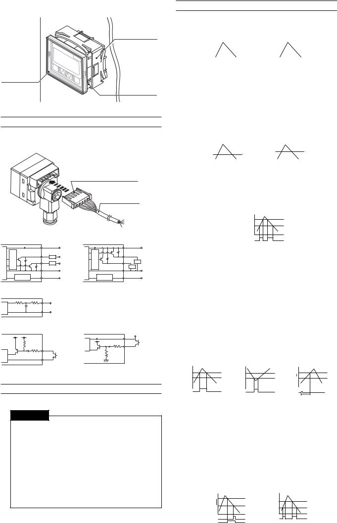
5. Connection Method and Diagrams
Insert the included connector-tipped cable into the sensor’s connector. Position the connector so that the side of the connector where the metallic contacts are visible is facing up.
Side where the metallic contacts are visible faces up.
Connector cable
Input/output circuit |
|
|
|
|
(AP-C30W/C31W/C33W) |
|
|||
|
|
Brown |
|
12 to 24 VDC |
circuitMain |
Overcurrent circuitprotection |
|
|
|
Blue |
|
|
||
|
|
Black Load |
5 to 40 VDC |
|
|
|
White Load |
5 to 40 VDC |
|
|
|
|
|
0V |
|
Input/output |
Analog output/ |
||
|
Pink zero shift input: switchable |
|||
|
circuit |
|
|
|
Analog output circuit |
|
|
|
|
|
|
Pink |
Analog |
|
Main circuit |
|
Blue |
|
|
|
output (1 to 5 V) |
|||
|
|
|
0 V |
|
Input/output circuit (AP-C30WP/C31WP/C33WP)
|
|
|
Brown |
12 to 24 VDC |
|
|
|
|
|
|
|
circuit Main |
circuit protection |
Overcurrent |
Black |
|
|
White |
Load |
|
|||
Load |
|
||||
Blue |
|
0V |
|||
|
|
|
|
|
|
|
|
Input/output |
|
Analog output/ |
|
|
|
Pink zero shift input: switchable |
|||
|
|
circuit |
|
|
|
Zero shift input circuit |
Zero shift input circuit |
(AP-C30W/C31W/C33W) |
(AP-C30WP/C31WP/C33WP) |
|
|
Main circuit |
Brown |
12 to 24 VDC |
|
|
Pink |
|
|
|
Pink |
|
|
|
Main circuit |
Blue |
|
|
|
(Short-circuit current 5 mA max.)
(Short-circuit current 5 mA max.)
Use non-contact input device such as open-collector.
6. Precautions for Safe Use
Follow these guidelines. Failure to do so may result in product damage.

 CAUTION
■ Connections
Input/output circuit
●Always ground the frame ground terminal when using an off-the-shelf switching regulator.
●Use separate conduits for power line and high voltage lines, since use of a common conduit may result in device malfunction.
●Improper wiring may result in the device becoming excessively hot or in device damage.
■Other
●Do not use this sensor with corrosive gasses or liquids.
●Do not insert objects such as wire into the pressure insertion area. Doing so may result in the device failing to operate properly due to damage to the pressure-sensitive elements.
●Do not use sharp-tipped objects to press the setting keys.
7.Detection Mode Operation
■General-purpose mode (F-1)
This mode allows the user to configure 2 detection points. Control output 1: Turns ON when pressure exceeds setting P1.
Control output 2: Turns ON when pressure exceeds setting P2.
<Output 1> |
|
|
<Output 2> |
|
||||
P1 |
|
|
|
|
P2 |
|
|
|
|
|
|
|
|
|
|
|
|
0 |
|
|
|
|
0 |
|
|
|
|
|
|
|
|
|
|
||
|
|
|
|
|
|
|
|
|
Output 1 |
OFF |
|
ON |
OFF |
Output 2 |
OFF |
ON |
OFF |
*Hysteresis is a standard 0.5% of F.S. when operating in general-pur- pose mode and application modes 1 and 2. During focus mode operation, it is 0.2% of F.S.
■Variable hysteresis mode (F-2)
Two detection points may be user-configured, and hysteresis for both may also be set.
Control output 1: Turns ON when pressure exceeds setting P1. Turns OFF when pressure drops the selected hysteresis amount below P1.
Control output 2: Turns ON when pressure exceeds setting P2. Turns OFF when pressure drops the selected hysteresis amount
|
|
below P2. |
|
|
|
|
|
|
|
|||
<Output 1> |
<Output 2> |
|||||||||||
P1 |
|
|
|
|
|
P2 |
|
|
|
|
|
|
|
|
|
|
|
|
|
|
|
|
H2 |
||
|
|
|
|
H1 |
|
|
|
|
|
|
|
|
0 |
|
|
|
|
|
0 |
|
|
|
|
|
|
Output 1 |
OFF |
ON |
OFF |
|
Output 2 |
OFF |
ON |
OFF |
|
|||
■Window mode (F-3)
The user may select a pair of upper (Hi) and lower (Lo) thresholds, and the sensor turns OFF when the pressure falls outside of the resulting range.
*Control output 1 is a standard 0.5% of F.S. During focus mode operation, it has a hysteresis of 0.2% of F.S., and control output 2 has a
hysteresis of 0.
<Output 1/Output 2>
Hi
Lo
0
Output1/Output2 OFF ON OFF ON OFF
■Application mode 1 (A-1)
This detection mode is optimum for use in suction detection applications.
Recommended sensor heads: AP-C30W/C30WP/C31W/C31WP Control output 1: Suction pressure detection.
Turns ON when pressure exceeds setting P1.
Control output 2: Detection and confirmation of vacuum burst pressure detection (or vacuum ultimate pressure).
Turns ON when the pressure falls below setting P2. *Cannot be used to detect vacuum burst pressure with
the AP-C31W/C31WP when operating in focus mode. Standard mode operation only.
Zero shift: The zero point is shifted immediately after the zero shift timer is set following the activation of zero shift input.
P1: Pressure setting for control output 1.
T1: Zero shift timer setting (ms) < Variable between 0 and 1,999 ms> P2: Pressure setting for control output 2.
*P2 is unrelated to zero shift and is always based on the current ambient pressure.
<Output 1> |
|
<Output 2> |
|
<Zero shift> |
||
P1 |
|
|
0 |
|
|
0 |
|
|
|
|
|
|
Shift |
0 |
|
|
P2 |
|
|
0 |
Output 1 OFF |
ON |
OFF |
Output 2 OFF |
ON |
OFF |
Zero shift input |
|
||||||
|
|
|
|
|
|
T1 |
■ Application mode 2 (A-2) |
|
|
|
|||
This mode is optimum for use in leak test applications. Recommended sensor head: AP-C33W/C33WP Control output 1: Leak pressure detection.
Turns ON when pressure falls below setting P1. *Output only when receiving zero shift input.
Control output 2: Window comparator output for detection of fill pressure. Turns OFF when pressure falls outside the range determined by upper (Hi) and lower (Lo) thresholds.
*Fill pressure values are displayed with the center pressure as 0 during focus mode operation.
P1: Pressure setting for control output 1.
Hi: Upper threshold setting for control output 2. Lo: Lower threshold setting for control output 2.
*The Hi and Lo values are unrelated to zero shift and are always based on the current ambient pressure.
|
|
<Output 1> |
|
<Output 2> |
|
|
|
0 |
|
|
|
|
|
|
P1 |
|
|
Hi |
|
|
|
|
|
|
|
|
|
|
|
|
|
Lo |
|
|
2 |
Output1 |
OFF |
ON |
Output 2 OFF |
OFF |
OFF |
|
|
|
|
|
ON |
ON |
|
Zero shift input |
OFF |
ON |
|
|
|
|
|
|
|
|
|
|
 Loading...