


IG Series
Table of contents
 Loading...
WARNINGWARNING
CAUTION
Note
WARNINGWARNING
WARNINGWARNING
96M11149
CCD
Thrubeam Type Laser Sensor
IG Series
Instruction manual
Read this instruction manual carefully prior to operating the IG Series CCD Thrubeam
Laser Sensor.
After reading, keep this manual in a safe place so that you can refer to it at any time.
• For details of each function, refer to “CCD Thrubeam Laser Sensor IG Series User’s
Manual”.
• You can download “CCD Thrubeam Laser Sensor IG Series User’s Manual” from
KEYENCE homepage (http://www.keyence.co.jp/).
Abnormal conditions
If the following conditions occur, turn off the power immediately. Continuing
to use this product under abnormal conditions may cause product failure.
• When water or foreign matter enters the IG Series
WARNINGWARNING
• When the IG Series is dropped or the case is damaged
• When the IG Series pr oduces smoke or an unpleasant smell
Precautions on use
• Use with the specified power source and voltage. Otherwise, fire, electric
shock or product failure may result.
WARNINGWARNING
•
Never disassemble or modify this product. Fire or electric shock may result.
• Before disconnecting the cables, make sure to turn off the main unit and
devices connected to the main unit. Otherwise, the unit could be
damaged.
CAUTION
• Do not turn off the power to the unit while it is being programmed. Some
or all of the set data may be lost.
Failure to follow these instructions may lead to injury.
Failure to follow these instructions may lead to product damage (product
malfunction, etc.).
This provides additional helpful information to ensure your understanding of
the unit's functions.
This references information that will aid your understanding of the text
Reference
.
descriptions.
Safety Information for IG series
General precautions
• At startup and during operation, be sure to monitor the functions and performance of this
product and confirm normal operation.
• We recommend that you take substantial safety measures to avoid any damage in the
event that a problem occurs.
• If the product is modified or used in any way other than described in the specifications, its
functions and performance cannot be guaranteed.
• Do not use this product for the purpose of protecting the human body.
• Do not subject this device to rapid temperature changes, otherwise product failure may
occur.
• The IG Series is intended for measuring objects. Do not use this product
for the purpose of protecti ng the human body.
• This product is not made with an explosion proof construction. Do not use
it in a location where any flammable gases, liquid, or powder exist.
Safety Precautions on Laser Product
• This product employs a semiconductor laser for its light source.
• Use of controls or adjustments or performance of procedures other than
those specified herein may result in hazardous radiation exposure.
• Follow the instructions mentioned in this manual. Otherwise, injur y to the
human body (eyes and skin) may result.
Precautions on class 1 laser products
• Do not disassemble this product. Laser emission from this product is not
automatically stopped when it is disassembled.
• Do not stare into the beam.
Sensor head IG-010/028
Wavelength 660 nm
Output 62 μW
Pulse width 48 μs
FDA(CDRH)Part1040.10* Class 1 Laser Product
IEC60825-1 Class 1 Laser Product
* The classification is based on IEC60825-1 standard following the Laser Notice No. 50 from
FDA (CDRH).
Laser emission stop input
When the laser emission stop input is activated, the laser emission stops by setting the
external input to ON (for 2 ms or more). The laser emission continues to stop while the
external input is ON. When the external input is set to OFF, the laser is emitted within 2 ms.
For details of the discrete outputs or analog output conditions during the laser emission
stop input, refer to the User’s Manual “11. External input”.
Installation environment
To ensure that it is being safely used, do not install this product in the following locations.
• High-humidity, dusty and poorly-ventilated locations.
• High-temperature locations where the unit is exposed to direct sunlight.
• Locations where there is corrosive gas or combustible gas.
• Locations where the unit may be directly subjected to vibration or impact.
• Locations where water, oil, or chemicals may splash onto the unit.
• Locations where the static electricity tend to be generated.
Influence of dirt
• Measurement errors may occur due to dust, water, oil, etc.
• Remove such dirt stuck to transmitter and receiver with either an air purge or wipe with a
soft cloth moistened with alcohol for heavy dirt. If the transmitter and receiver get
scratched, measurement errors may occur.
• Remove dirt attached to the target with either an air purge or it off.
• If dirt is floating within the measurement range, take adequate measures, such as
installing a dust protection cover or air purging.
Anti-noise prevention
When the unit is installed near a noisy source such as a power generator or high-voltage
line, operational errors or product failure may occur. Take adequate measures such as
using a noise filter, arranging cords appropriately, or insulating the amplifier and sensor
head.
Warm up
Wait approximately 10 minutes after power up before using the IG series so as to allow
forthe display value to stabilize upon warm up.
Other Precautions
Power source
• Operation errors may occur due to noise superimposed upon the power source. Make
certain to use the direct current stabilized power source which uses an insulation
transformer.
• When using a commercially available switching regulator, make sure to properly ground
the frame.
Precautions on UL Certificate
The IG series complies with the following UL and CSA standards. The IG series has
obtained UL and C-UL certificate.
• Applicable standardUL508 Industrial Control Equipment
CAN/CSA C22.2 No.14-M05 Industrial Control Equipment
• UL File No.E301717
• UL category: NRKH, NRKH7
Precautions
• The IG series must have its power supplied from a Class 2 power source according to
NFPA70 (NEC: National Electrical Code).
• The UL certificate for the IG series is for the sensor head and amplifier used in
combination. The IG series sensor head must be used together with the IG series sensor
amplifier unit exclusively.
• Power supply/Control input/Control output shall be connected to a single Class2 source
only.
• Use with over current protection device which is rated 30V or more and not more than 1A.
1
Checking the Package Contents
Before using the unit, confirm that the parts and equipment listed below are included in the
package of the model you purchased.
Sensor amplifier
z DIN rail mount type
IG-1000 (main unit)
Amplifier x 1 Instruction manual x 1
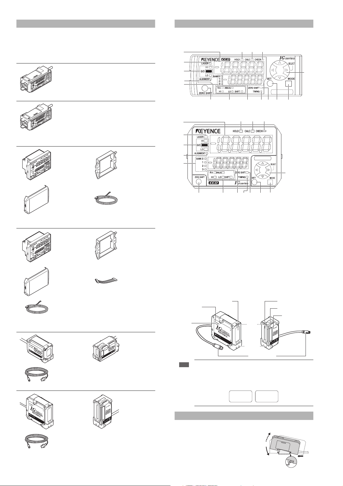
Part names
Sensor amplifier
z DIN rail mount type (IG-1000/IG-1050)
(1)
(2)
(3)
(4)
(5)
(16) (15) (14)
(13)
IG-1050 (expansion unit)
z Panel mount type
IG-1500 (main unit)
Instruction manual x 1
IG-1550 (expansion unit)
Sensor head
IG-010 (10 mm width)
Amplifier x 1
Amplifier x 1
Front protection
cover
x 1
Amplifier x 1
Front protection
cover
×1
Input-output cable
(2 m) x 1
(Number of cable
cores: 8)
Panel mounting
tool
x 1
Power/Inputoutput cable (2 m)
x 1
(Number of cable
cores: 12)
Panel mounting
tool
×1
Expansion cable
(50 mm) x 1
(7) (8) (9)
(11) (12)(10)(6)
z Panel mount type (IG-1500/IG-1550)
(1)
(16) (15) (14)
(2)
(3)
(4)
(5)
(1) Main display
(2) Laser emission indicator [LASER]
(3) Judgment indicator [HI / GO / LO]
(4) Optical axis alignment indicator [ALIGNMENT]
(5) Bank indicator [BANK 0 to 3]
(6) Zero shift button [ZERO SHIFT]
(7) Sub display identification indicator [R.V. / ANALOG / HI / LO / SHIFT]
(8) Sub display
(9) Timing input indicator [TIMING]
(10)Zero shift indicator [ZERO SHIFT]
(11)SET button [SET]
(12)MODE button [MODE]
(13) Arrow buttons
(14) Check indicator [CHECK]
(15) Calculation indicator [CALC]
(16)Hold indicator [HOLD]
(7) (8) (9)
(11) (12)(10)(6)
Sensor head
Transmitter Receiver
Optical axis
alignment
indicator
Power
indicator
Laser transmitter
Top
Laser Receiver
Position monitor
(13)
Optical axis
alignment
indicator
Transmitter (T) x 1 Receiver (R) x 1
Sensor head
connection cable
(2 m)
IG-028 (28 mm width)
Transmitter (T) x 1 Receiver (R) x 1
Sensor head
connection cable
(2 m)
We have thoroughly inspected the package contents before shipmen t. However, in the event
of defective or broken items, please contact your nearest KEYENCE office.
x 2
x 2
Use the transmitter and receiver in combination with the same serial
Note
number. If they are used in combination with different ser ial numbers, the
operation and accuracy are not guaranteed. The serial number is located on
top of the transmitter and receiver.
Transmitter
SERIAL No.
12345678
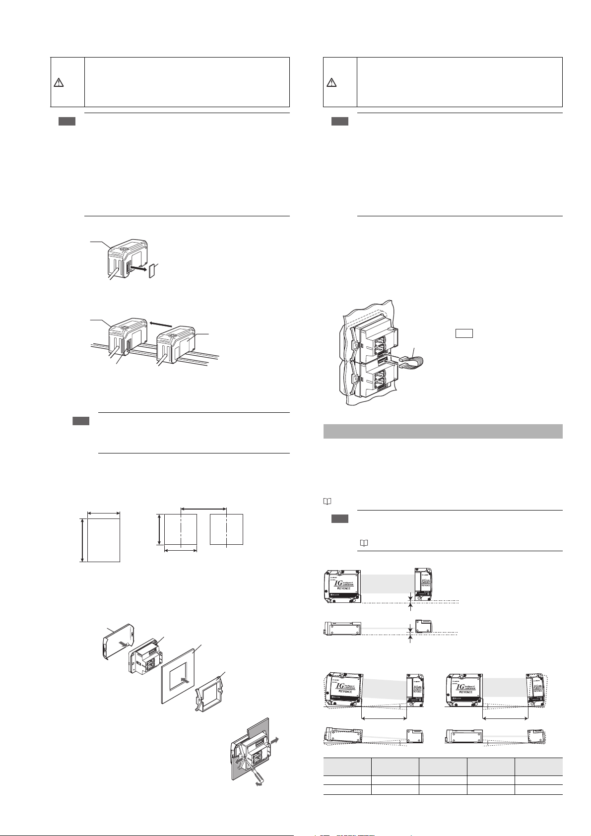
Mounting the Amplifier
DIN rail mount type, main unit (IG-1000)
Align the claw at the bottom of the main body with the
DIN rail. While pushing the main body in the direction
of the arrow (1), tilt the amplifier in the direction of the
arrow (2).
To remove the amplifier, raise the main body in the
direction of the arrow (3) while pushing it in the
direction of the arrow (1).
2
Bottom
Connector
Receiver
No.
12345678
(3)
(2)
(1)
DIN rail mount type, expansion unit (IG-1050)
CAUTION
Note
Connector cover
Main unit
Connecter
Expansion unit
Main unit
· Thickness of the panel mounting part 1 to 6 mm
· X = 48 × (Number of amplifier) - 3
+ 0.6
- 0
45 mm
+ 0.6
- 0
45 mm
+ 0.6
- 0
45 mm
X mm
Minimum 85 mm
When arranging
lengthwise to attach
When arranging widthwise
to attach
Panel mounting tool
Panel
Sensor amplifier
Front protection cover
Up to 3 expansion units can be connected to one main unit.
•
When connecting multiple amplifiers (expansion units), first check to make sure
that the power is turned off to all of the main and expansion units. Connecting
the units with the power turned on could damage them.
•
Push the amplifiers (expansion units) as far as possible into the main unit. If they
are connected at an angle or not inserted securely, the units could get damaged.
Panel mount type, expansion unit (IG-1550)
Up to 3 expansion units can be connected to one main unit.
• When connecting the expansion cable, make sure to turn off the power
beforehand. Inserting or removing the cable with the power turned on may
cause damage to the units.
CAUTION
• Push the expansion cable connector securely all the way. If it is connected
at an angle or not inserted securely, the units could get damaged.
• When connecting the expansion units, make sure to initialize the
Note
expansion units and set the output polarity.
(1) When turning on the amplifier for the first ti me after connecting the sensor head
please reference
“Operation When the Power is Turned on for the First Time” (page 6)
(2) When initializing the unit please reference
“Initial Reset (Initialize)” (page 7)
•
Expansion units with different setting of output polarity (such as an NPN output
expansion unit to a PNP output main unit) cannot be connected together.
• Expansion units using DIN rail mount cannot be connected to a panel
mount style main unit.
1 Remove the expansion protective cover from the IG-1000 (main unit).
2 Install the amplifiers (main and expansion units) onto the DIN rail.
3
Push the expansion unit into the main unit connector until a clicking sound can be heard.
4 Install the end units (OP-26751: 2 units per set) (sold separately) on both sides of the
amplifiers (main or expansion units). Secure the end units in place with screws on top
(2 on each end unit).
The end units are mounted in the same way as the amplifiers.
Mount the amplifiers securely using the end units (OP-26751: 2 units
per set) (sold separately) or a commercially available DIN rail mounting
tool to prevent the amplifiers from slipping and coming off from the DIN
rail due to machine vibration.
Panel mount type, main unit (IG-1500)
1 Make a hole on the panel to attach according to the measurement below.
• When connecting the expansion units, make sure to initialize the
Note
1
2 Install the amplifiers (expansion units) on the panel.
3
connected expansion units and set the output polarity.
(1)
When turning on the amplifier for the first time after connecting the sensor head
please reference
“Operation When the Power is Turned on for the First Time” (page 6)
(2) When initializing the unit please reference
“Initial Reset (Initialize)” (page 7)
•
Expansion units with different setting of output polarity (such as an NPN output
expansion unit to a PNP output main unit) cannot be connected together.
• Expansion units using panel mount cannot be connected to a DIN rail
mounted main unit.
Make the appropriate number of hole in the panel according to the number of
amplifiers required (main and connected expansion units).
For the panel cutting measurement, refer to the “Panel mount type, main unit”.
For the amplifier mounting method, refer to the “Panel mount type, main unit”.
Connect the
supplied with the expansion unit.
amplifiers (
main
and expansion units)
Expansion
cable
using the expansion cable (50 mm
When arranging the
amplifiers as depicted in
the pictorial on the left, the
Reference
300 mm expansion cable
(OP-35361) is required.
Mounting the Sensor Head
If the mounting distance between the transmitter and receiver is as follows, the optical axis
alignment is not required when mounting within the “parallel acceptable range” and “tilt
acceptable range”.
• IG-010 : 3 to 500 mm
• IG-028 : 50 to 500mm
However if the distance is out of the above range(s), adjust the optical axis after mounting.
“Optical axis alignment” (page 6)
The minimum detectable object, linearity and temperature characteristics
Note
found in the specifications are valid only if the sensor head is mounted within
the “parallel acceptable range” and “tilt acceptable range”.
“Specifications” (page 10)
z Parallel acceptable range
)
2 Insert the back side of amplifier to the hole of the panel.
3 Arrange the panel mounting tool in the direction below, mount to the amplifier from the
back and attach the front protection cover to the amplifier.
To remove the panel mounting tool, widen the
claws at both ends of the panel mounting tool using
a slotted screwdriver, as demonstrated in the
pictorial on the right.
Transmitter Receiver
Transmitter Receiver
within ± 0.5 mm
within ± 0.5 mm
z Tilt acceptable range
Tilt of transmitter Tilt of receiver
Transmitter Receiver
Mounting distance
Transmitter Receiver
Mounting
distance
500 mm or less within ±0.05° within ±0.05° within ±1° within ±2°
100 mm or less within ±0.2° within ±0.2° within ±1° within ±2°
3
AC
B
A B C D
Transmitter Receiver
Mounting distance
Transmitter Receiver
D
Loading...