


 Loading...
Illustrated Parts Manual
Models 600SC 600SJC 660SJC
PRIOR TO
S/N 0300128000
Caterpillar Chassis &
Prior to ADE System
3120795
September 10, 2013
REVISION LOG
Note: Machines with S/Ns 0300071456, 0300071859, 0300072679, 0300072703, 0300072794 & 0300072807 have the Gradall Chassis but are not equipped with the ADE System. Use JLG Parts Manual p/n 3121158 for Gradall Chassis components.
January 15, 2000 - Original Issue Of Manual
July 15, 2000 - Revised (Edited to B/M 0010568 Revision 1)
October 15, 2000 - Revised (Edited to B/M 0010568 Revision 2)
May 31, 2001 - Revised (Edited to B/M 0010568 Revision 7)
January 3, 2002 - Revised (Edited to B/M 0010568 Revision 10)
January 8, 2003 - Revised (Edited to B/M 0010568 Revision 18)
April 21, 2003 - Revised (Edited to B/M 0010568 Revision 19)
July 15, 2003 - Revised
November 10, 2003 - Revised
March 9, 2004 - Revised
January 18, 2007 - Revised
June 1, 2007 - Revised
September 26, 2007 - Revised
January 15, 2008 - Revised
February 2, 2009 - Revised
November 20, 2009 - Revised
January 31, 2011 - Revised
May 20, 2011 - Revised
August 5, 2011 - Revised
December 6, 2011 - Revised
May 4, 2012 - Revised
July 26, 2012 - Revised
November 19, 2012 - Revised
March 20, 2013 - Revised
June 30, 2013 - Revised
September 10, 2013 - Revised
3120795 |
A |
REVISION LOG
B |
3120795 |
TABLE OF CONTENTS
FIGURE NO. |
TITLE |
PAGE NO. |
|
SECTION |
1 - FRAME . . . . . . . . . . . . . . . . . . . . . . . . . . . . . . . . . . . . . . . . . . . . . . . . . . . |
. . .1-1 |
|
1-1 |
|
FRAME ASSEMBLY . . . . . . . . . . . . . . . . . . . . . . . . . . . . . . . . . . . . . . . . . . . . . . . . . |
. . . 1-2 |
1-2 |
|
TRACK SHOE ASSEMBLY . . . . . . . . . . . . . . . . . . . . . . . . . . . . . . . . . . . . . . . . . . . |
. . . 1-4 |
1-3 |
|
DRIVE AND SPROCKET INSTALLATION . . . . . . . . . . . . . . . . . . . . . . . . . . . . . . . . |
. . . 1-6 |
1-4 |
|
DRIVE MOTOR ASSEMBLY . . . . . . . . . . . . . . . . . . . . . . . . . . . . . . . . . . . . . . . . . . |
. . . 1-8 |
1-5 |
|
DRIVE HUB ASSEMBLY . . . . . . . . . . . . . . . . . . . . . . . . . . . . . . . . . . . . . . . . . . . . . |
. . . 1-10 |
1-6 |
|
DRIVE VALVE ASSEMBLY . . . . . . . . . . . . . . . . . . . . . . . . . . . . . . . . . . . . . . . . . . . |
. . . 1-14 |
1-7 |
|
ROLLER ASSEMBLIES INSTALLATION . . . . . . . . . . . . . . . . . . . . . . . . . . . . . . . . . |
. . . 1-16 |
1-8 |
|
IDLER ASSEMBLY . . . . . . . . . . . . . . . . . . . . . . . . . . . . . . . . . . . . . . . . . . . . . . . . . |
. . . 1-18 |
1-9 |
|
TRACK ADJUSTER ASSEMBLY . . . . . . . . . . . . . . . . . . . . . . . . . . . . . . . . . . . . . . . . |
. . . 1-20 |
SECTION |
2 - TURNTABLE . . . . . . . . . . . . . . . . . . . . . . . . . . . . . . . . . . . . . . . . . . . . . . |
. . .2-1 |
|
2-1 |
|
CONTROL VALVES INSTALLATIONS . . . . . . . . . . . . . . . . . . . . . . . . . . . . . . . . . . . |
. . . 2-2 |
2-2 |
|
MAIN CONTROL VALVE ASSEMBLY . . . . . . . . . . . . . . . . . . . . . . . . . . . . . . . . . . . |
. . . 2-6 |
2-3 |
|
ARTICULATING JIB VALVE ASSEMBLY . . . . . . . . . . . . . . . . . . . . . . . . . . . . . . . . . |
. . . 2-10 |
2-4 |
|
SWING DRIVE, TURNTABLE BEARING & LOCK INSTALLATIONS . . . . . . . . . . . . |
. . . 2-12 |
2-5 |
|
SWING HUB ASSEMBLY . . . . . . . . . . . . . . . . . . . . . . . . . . . . . . . . . . . . . . . . . . . . . |
. . . 2-16 |
2-6 |
|
SWING BRAKE ASSEMBLY . . . . . . . . . . . . . . . . . . . . . . . . . . . . . . . . . . . . . . . . . . |
. . . 2-18 |
2-7 |
|
SWING MOTOR ASSEMBLY (WHITE ROLLER STATOR) . . . . . . . . . . . . . . . . . . |
. . . 2-22 |
2-8 |
|
SWING MOTOR ASSEMBLY (PARKER) . . . . . . . . . . . . . . . . . . . . . . . . . . . . . . . . . |
. . . 2-24 |
2-9 |
|
DEUTZ ENGINE INSTALLATION . . . . . . . . . . . . . . . . . . . . . . . . . . . . . . . . . . . . . . |
. . . 2-26 |
2-10 |
|
GENERATOR INSTALLATION - DEUTZ MACHINES (OPTIONAL) . . . . . . . . . . . . . |
. . . 2-32 |
2-11 |
|
PISTON PUMP ASSEMBLY . . . . . . . . . . . . . . . . . . . . . . . . . . . . . . . . . . . . . . . . . . . |
. . . 2-36 |
2-12 |
|
GEAR PUMP ASSEMBLY . . . . . . . . . . . . . . . . . . . . . . . . . . . . . . . . . . . . . . . . . . . . . |
. . . 2-42 |
2-13 |
|
TANK INSTALLATIONS . . . . . . . . . . . . . . . . . . . . . . . . . . . . . . . . . . . . . . . . . . . . . . |
. . . 2-44 |
2-14 |
|
ROTARY COUPLING INSTALLATION . . . . . . . . . . . . . . . . . . . . . . . . . . . . . . . . . . |
. . . 2-46 |
2-15 |
|
GROUND CONTROL BOX ASSEMBLY . . . . . . . . . . . . . . . . . . . . . . . . . . . . . . . . . |
. . . 2-48 |
2-16 |
|
ELECTRICAL OPTIONS INSTALLATION (TURNTABLE MOUNTED) . . . . . . . . . . . |
. . . 2-52 |
2-17 |
|
ENGINE TRAY JACK INSTALLATION (OPTIONAL) . . . . . . . . . . . . . . . . . . . . . . . . |
. . . 2-56 |
2-18 |
|
HOODS & LIFTING PLATE INSTALLATIONS . . . . . . . . . . . . . . . . . . . . . . . . . . . . |
. . . 2-58 |
SECTION 3 - BOOM. . . . . . . . . . . . . . . . . . . . . . . . . . . . . . . . . . . . . . . . . . . . . . . . . . . . . . .3-1
3-1 BOOM INSTALLATIONS - 600SC . . . . . . . . . . . . . . . . . . . . . . . . . . . . . . . . . . . . . . . . . 3-2 3-2 BOOM INSTALLATIONS - 600SJC & 660SJC . . . . . . . . . . . . . . . . . . . . . . . . . . . . . . . . 3-6 3-3 MAIN BOOM ASSEMBLIES . . . . . . . . . . . . . . . . . . . . . . . . . . . . . . . . . . . . . . . . . . . . . . 3-10 3-4 ROTATOR ASSEMBLIES (FRONT ENTRY PLATFORM) . . . . . . . . . . . . . . . . . . . . . . . . 3-14 3-5 ROTATOR ASSEMBLIES (SIDE ENTRY PLATFORM) . . . . . . . . . . . . . . . . . . . . . . . . . 3-18 3-6 POWER TRACK INSTALLATIONS - PLASTIC TRACK . . . . . . . . . . . . . . . . . . . . . . . . . 3-20 3-7 POWER TRACK INSTALLATIONS - STEEL TRACK . . . . . . . . . . . . . . . . . . . . . . . . . . . 3-24 3-8 BOOM WIPERS INSTALLATION (OPTIONAL) . . . . . . . . . . . . . . . . . . . . . . . . . . . . . . . 3-28
SECTION 4 - PLATFORM. . . . . . . . . . . . . . . . . . . . . . . . . . . . . . . . . . . . . . . . . . . . . . . . . . .4-1
4-1 PLATFORM COMPONENTS INSTALLATION (FRONT ENTRY) . . . . . . . . . . . . . . . . . . 4-2 4-2 PLATFORM COMPONENTS INSTALLATION (SIDE ENTRY) . . . . . . . . . . . . . . . . . . . . 4-6 4-3 PLATFORM CONSOLE ASSEMBLY . . . . . . . . . . . . . . . . . . . . . . . . . . . . . . . . . . . . . . . 4-10 4-4 CONTROLLER ASSEMBLY (SWING AND LIFT) . . . . . . . . . . . . . . . . . . . . . . . . . . . . . . 4-16 4-5 CONTROLLER ASSEMBLY (DRIVE AND STEER) . . . . . . . . . . . . . . . . . . . . . . . . . . . . 4-18
3120795 |
600SC 600SJC 660SJC |
i |
TABLE OF CONTENTS
FIGURE NO. |
TITLE |
PAGE NO. |
SECTION 5 - CYLINDER . . . . . . . . . . . . . . . . . . . . . . . . . . . . . . . . . . . . . . . . . . . . . . . . . . .5-1
5-1 LEVEL CYLINDER ASSEMBLY - 600SC . . . . . . . . . . . . . . . . . . . . . . . . . . . . . . . . . . . . . 5-2 5-2 LEVEL CYLINDER ASSEMBLIES - 600SJC & 660SJC. . . . . . . . . . . . . . . . . . . . . . . . . . 5-4 5-3 LIFT CYLINDER ASSEMBLY . . . . . . . . . . . . . . . . . . . . . . . . . . . . . . . . . . . . . . . . . . . . . 5-6 5-4 ARTICULATING JIB LIFT CYLINDER ASSEMBLY - 600SJC & 660SJC . . . . . . . . . . . . . 5-10 5-5 MASTER CYLINDER ASSEMBLIES . . . . . . . . . . . . . . . . . . . . . . . . . . . . . . . . . . . . . . . . 5-12 5-6 TELESCOPE CYLINDER ASSEMBLIES . . . . . . . . . . . . . . . . . . . . . . . . . . . . . . . . . . . . . 5-16 5-7 CYLINDER BELLOWS INSTALLATIONS (OPTIONAL) . . . . . . . . . . . . . . . . . . . . . . . . . 5-18
SECTION 6 - HYDRAULIC . . . . . . . . . . . . . . . . . . . . . . . . . . . . . . . . . . . . . . . . . . . . . . . . . .6-1
6-1 HYDRAULIC DIAGRAM (PRIOR TO S/N 0300064782) . . . . . . . . . . . . . . . . . . . . . . . . . 6-2 6-2 HYDRAULIC DIAGRAM (S/N 0300064782 TO S/N 0300065090). . . . . . . . . . . . . . . . . . 6-8 6-3 HYDRAULIC DIAGRAM (S/N 0300065090 TO S/N 0300070773) . . . . . . . . . . . . . . . . . 6-14 6-4 HYDRAULIC DIAGRAM (S/N 0300070773 TO S/N 0300128000) . . . . . . . . . . . . . . . . . 6-20 6-5 HYDRAULIC DIAGRAM LIST . . . . . . . . . . . . . . . . . . . . . . . . . . . . . . . . . . . . . . . . . . . . . . 6-26
SECTION 7 - ELECTRICAL . . . . . . . . . . . . . . . . . . . . . . . . . . . . . . . . . . . . . . . . . . . . . . . . .7-1
7-1 ELECTRICAL DIAGRAM LIST . . . . . . . . . . . . . . . . . . . . . . . . . . . . . . . . . . . . . . . . . . . . . 7-2 7-2 ELECTRICAL SCHEMATIC - DEUTZ ENGINE (PRIOR TO S/N 0300064782) . . . . . . . . 7-4 7-3 ELECTRICAL SCHEMATIC - DEUTZ ENGINE(S/N 0300064782 TO
S/N 0300128000) . . . . . . . . . . . . . . . . . . . . . . . . . . . . . . . . . . . . . . . . . . . . . . . . . . . 7-6 7-4 HARNESS COMPONENTS INSTALLATION . . . . . . . . . . . . . . . . . . . . . . . . . . . . . . . . . 7-8
SECTION 8 - DECALS . . . . . . . . . . . . . . . . . . . . . . . . . . . . . . . . . . . . . . . . . . . . . . . . . . . . .8-1
8-1 |
DECALS INSTALLATION (STANDARD) . . . . . . . . . . . . . . . . . . . . . . . . . . . . . . . . . . . . |
8-2 |
8-2 |
DECALS INSTALLATION (COUNTRY SPECS) . . . . . . . . . . . . . . . . . . . . . . . . . . . . . . . |
8-6 |
SECTION 9 - RECOMMENDED SERVICE PARTS STOCK. . . . . . . . . . . . . . . . . . . . . . . . .9-1 SECTION 10 - SPECIAL OPTIONS . . . . . . . . . . . . . . . . . . . . . . . . . . . . . . . . . . . . . . . . . . .10-1 SECTION 11 - PARTS NUMBER INDEX . . . . . . . . . . . . . . . . . . . . . . . . . . . . . . . . . . . . . . .11-1
ii |
600SC 600SJC 660SJC |
3120795 |
|
SECTION 1 FRAME |
|
|
|
|
|
|
|
S |
|
|
|
|
|
|
|
|
|
|
|
|
E |
|
|
TABLE OF CONTENTS |
|
|
|
|
|
|
|
|
C |
|
FIGURE |
DESCRIPTION |
PAGE |
|
T |
|
|
|
|
|||
|
|
|
|
I |
|
1-1 |
FRAME ASSEMBLY |
1-2 |
|
|
|
|
|
|
|||
1-2 |
TRACK SHOE ASSEMBLY. . . . . . . . . . . . . . . . . . . . . . . . . . . . . . . . . . . . . . . . . . . . . . . . . . |
. 1-4. . |
|
O |
|
1-3 |
DRIVE AND SPROCKET . . . . . . . . . . . . . . . . . . . . . . . . . . . . . . . . . . . . . . . . . . . . . . . . . . . |
1-6. . . |
|
|
|
1-4 |
DRIVE MOTOR ASSEMBLY . . . . . . . . . . . . . . . . . . . . . . . . . . . . . . . . . . . . . . . . . . . . . . . . . |
. 1-8. . |
|
N |
|
1-5 |
DRIVE HUB ASSEMBLY. . . . . . . . . . . . . . . . . . . . . . . . . . . . . . . . . . . . . . . . . . . . . . . . . . . . |
. 1-10. . |
|
|
|
1-6 |
DRIVE VALVE ASSEMBLY . . . . . . . . . . . . . . . . . . . . . . . . . . . . . . . . . . . . . . . . . . . . . . . . . . |
. 1-14. . |
|
1 |
|
1-7 |
ROLLER ASSEMBLIES INSTALLATION . . . . . . . . . . . . . . . . . . . . . . . . . . . . . . . . . . . . . . . |
. 1-16. . |
|
|
|
1-8 |
IDLER ASSEMBLY . . . . . . . . . . . . . . . . . . . . . . . . . . . . . . . . . . . . . . . . . . . . . . . . . . . . . . . . |
. 1-18. . |
|
F |
|
1-9 |
TRACK ADJUSTER ASSEMBLY |
1-20 |
|
|
|
|
|
|
|||
|
|
|
|
R |
|
|
|
|
|
A |
|
|
|
|
|
M |
|
|
|
|
|
E |
|
|
|
|
|
|
|
|
|
|
|
|
|
3120795 |
1-1 |

|
SECTION 1 FRAME |
S |
FIGURE 1-1. FRAME ASSEMBLY |
E |
|
C |
|
T |
|
I |
|
O |
|
N |
|
1 |
|
F |
|
R |
|
A |
|
M |
|
E |
|
1-2 |
3120795 |

SECTION 1 FRAME
.
FIGURE 1-1. FRAME ASSEMBLY
FIG & ITEM # |
PART NUMBER |
DESCRIPTION |
QTY. |
REV. |
|
|
|
|
|
|
|
FRAME OPTIONS: |
Ref. |
|
|
|
Frame Weldment - with Steel Track Options: |
|
|
|
2360529 |
600SC - Prior to S/N 0300064782 |
|
|
|
2360578 |
600SC - S/N 0300064782 to S/N 0300067081 |
|
|
|
2360582 |
600SC - S/N 0300067081 to S/N 0300128000 |
|
|
|
2360440 |
600SJC - Prior to S/N 0300064782 |
|
|
|
2360579 |
600SJC - S/N 0300064782 to S/N 0300067081 |
|
|
|
2360583 |
600SJC - S/N 0300067081 to S/N 0300128000 |
|
|
|
2360528 |
660SJC - Prior to S/N 0300064782 |
|
|
|
2360580 |
660SJC - S/N 0300064782 to S/N 0300067081 |
|
|
|
2360584 |
660SJC - S/N 0300067081 to S/N 0300128000 |
|
|
|
2360439 |
COMPLETE FRAME ASSEMBLY (STEEL TRACK) |
Ref. |
|
1 |
7022708 |
Track Shoe Assembly (See Figure 1-2 for Breakdown) |
2 |
|
2 |
|
Drive Assembly (See Figure 1-3 for Breakdown) |
2 |
|
|
7022677 |
Prior to S/N 0300067081 |
|
|
|
NPN |
S/N 0300067081 to S/N 0300128000 |
|
|
3 |
See Note |
Sprocket Installation (See Figure 1-3 for Breakdown) |
2 |
|
|
|
(Note: Not Available - Purchase Complete Assembly) |
|
|
4 |
See Note |
Motor Guard Installation (See Figure 1-3 for Breakdown) |
2 |
|
|
|
(Note: Not Available - Purchase Complete Assembly) |
|
|
5 |
See Note |
Roller Assemblies Installation (See Figure 1-7 for |
2 |
|
|
|
Breakdown) |
|
|
|
|
(Note: Not Available - Purchase Complete Assembly) |
|
|
6 |
See Note |
Track Guide Installation |
2 |
|
|
|
(Note: Not Available - Purchase Complete Assembly) |
|
|
|
7022675 |
Guide (1 Per Side) |
2 |
|
|
7022644 |
Bolt M16 x 35mm (4 Per Side) |
8 |
|
|
7022647 |
Washer 3.50mm (4 Per Side) |
8 |
|
7 |
See Note |
Idler Assembly (See Figure 1-8 for Breakdown) |
2 |
|
|
|
(Note: Not Available - Purchase Complete Assembly) |
|
|
|
0257440 |
BEARING ADAPTER PLATE INSTALLATION |
Ref. |
B |
101 |
0100019 |
Compound, Locking |
A/R |
|
102 |
0682028 |
Bolt 5/8in-11NC x 3-1/2in (Grade 8) |
30 |
|
103 |
3272001 |
Nut 5/8in-11NC |
30 |
|
104 |
4845456 |
Adapter Weldment |
1 |
|
105 |
4892000 |
Washer, Hardened 5/8in |
60 |
|
|
|
|
|
|
S E C T I O N
1
F
R A M E
3120795 |
1-3 |
|
SECTION 1 FRAME |
S |
FIGURE 1-2. TRACK SHOE ASSEMBLY |
E |
|
C |
|
T |
|
I |
|
O |
|
N |
|
1 |
|
F |
|
R |
|
A |
|
M |
|
E |
|
|
|
1-4 |
3120795 |
SECTION 1 FRAME
.
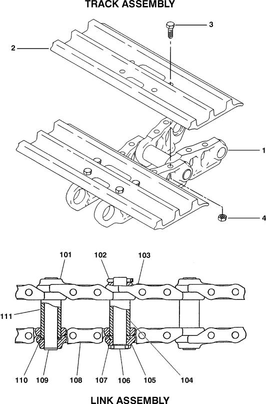
FIGURE 1-2. TRACK SHOE ASSEMBLY
FIG & ITEM # |
PART NUMBER |
DESCRIPTION |
QTY. |
REV. |
|
|
|
|
|
|
7022708 |
TRACK SHOE ASSEMBLY - STEEL |
Ref. |
|
1 |
7022680 |
Link Assembly (See Items 101-111 for Breakdown) |
1 |
|
2 |
7022602 |
Shoe, Track Options: |
43 |
|
3 |
7022612 |
Bolt M16 x 46mm |
172 |
|
4 |
7022614 |
Nut M16 x 46mm |
172 |
|
|
7022680 |
LINK ASSEMBLY |
Ref. |
|
101 |
7022606 |
Link, Track |
42 |
|
102 |
7022652 |
Pin, Cotter |
1 |
|
103 |
7022608 |
Link, Track (Master) |
1 |
|
104 |
7022651 |
Bushing |
1 |
|
105 |
7022609 |
Link, Track (Master) |
1 |
|
106 |
7022664 |
Pin (Master Link) |
1 |
|
107 |
7022683 |
Spacer |
2 |
|
108 |
7022607 |
Link, Track (Standard) |
42 |
|
109 |
7022615 |
Pin (Standard Link) |
42 |
|
110 |
7022616 |
Washer, Seal |
172 |
|
111 |
7022679 |
Bushing |
42 |
|
|
0270107 |
RUBBER PAD INSTALLATION (OPTIONAL - NOT SHOWN) |
Ref. |
A |
|
|
Note: Used as a cover over steel track shoes only. |
Ref. |
|
|
3340887 |
Pad, Rubber Cover |
86 |
|
|
|
|
|
|
S E C T I O N
1
F
R A M E
3120795 |
1-5 |
|
SECTION 1 FRAME |
S |
FIGURE 1-3. DRIVE AND SPROCKET INSTALLATION |
E |
|
C |
|
T |
|
I |
|
O |
|
N |
|
1 |
|
F |
|
R |
|
A |
|
M |
|
E |
|
1-6 |
3120795 |
|
|
SECTION 1 FRAME |
|
|
|
S |
|
. |
|
|
|
|
|
|
|
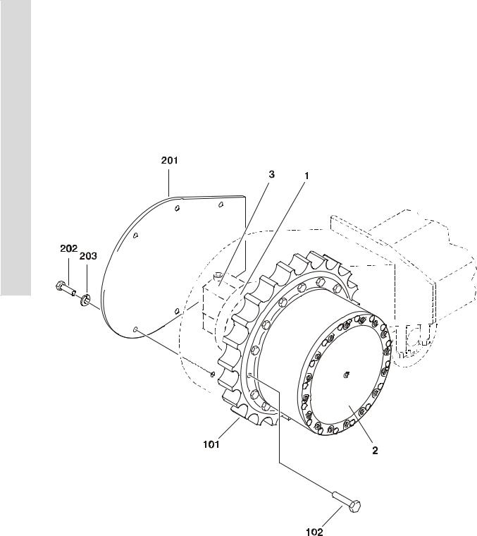
FIGURE 1-3. DRIVE AND SPROCKET INSTALLATION |
|
|
|
E |
|
||
|
|
|
|
|
|||
|
|
|
|
|
|
C |
|
FIG & ITEM # |
PART NUMBER |
DESCRIPTION |
QTY. |
REV. |
|
|
|
|
|
|
|
|
|
T |
|
|
|
DRIVE ASSEMBLY |
Ref. |
|
|
|
|
|
7022677 |
Prior to S/N 0300067081 |
Ref. |
|
|
I |
|
|
|
|
|
|
|||
|
NPN |
S/N 0300067081 to S/N 0300128000 |
Ref. |
|
|
O |
|
|
|
|
|
|
|
|
|
1 |
|
Drive Motor Assembly Options (See Figure 1-4 for |
1 |
|
|
N |
|
|
|
|
|
|
|||
|
|
Breakdown): |
|
|
|
|
|
|
7022718 |
Prior to S/N 0300067081 |
|
|
|
1 |
|
|
See Note |
S/N 0300067081 to S/N 0300128000 |
|
|
|
|
|
|
|
|
|
|
|
||
|
|
(Note: Not Available for Purchase.) |
|
|
|
|
|
2 |
|
Drive Hub Assembly Options (See Figure 1-5 for Break- |
1 |
|
|
F |
|
|
|
down): |
|
|
|
|
|
|
|
|
|
|
|
|
|
|
7022678 |
Prior to S/N 0300067081 |
|
|
|
R |
|
|
7022737 |
S/N 0300067081 to S/N 0300128000 |
|
|
|
|
|
3 |
7022715 |
Drive Valve Assembly (See Figure 1-6 for Breakdown): |
1 |
|
|
A |
|
|
|
SPROCKET INSTALLATION |
Ref. |
|
|
M |
|
|
|
|
|
E |
|
||
|
|
|
|
|
|
||
101 |
7022605 |
Sprocket |
1 |
|
|
|
|
102 |
See Note |
Bolt M16 x 40mm (Note: Not Available for Purchase.) |
15 |
|
|
|
|
|
|
|
|
||||
|
|
COVER INSTALLATION |
Ref. |
|
|
|
|
201 |
7022613 |
Plate, Cover |
2 |
|
|
|
|
202 |
See Note |
Bolt M12 x 25mm (Note: Not Available for Purchase.) |
12 |
|
|
|
|
203 |
7022617 |
Washer, Hardened |
12 |
|
|
|
|
|
|
|
|
|
|
|
|
3120795 |
1-7 |
|
SECTION 1 FRAME |
S |
FIGURE 1-4. DRIVE MOTOR ASSEMBLY |
E |
|
C |
|
T |
|
I |
|
O |
|
N |
|
1 |
|
F |
|
R |
|
A |
|
M |
|
E |
|
|
|
1-8 |
3120795 |
|
|
SECTION 1 FRAME |
|
|
|
S |
|
. |
|
|
|
|
|
|
|
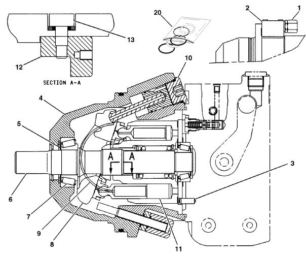
FIGURE 1-4. DRIVE MOTOR ASSEMBLY |
|
|
|
E |
|
||
|
|
|
|
|
|||
|
|
|
|
|
|
C |
|
FIG & ITEM # |
PART NUMBER |
DESCRIPTION |
QTY. |
REV. |
|
|
|
|
|
|
|
|
|
T |
|
|
7022718 |
DRIVE MOTOR ASSEMBLY (PRIOR TO S/N 0300067081) |
Ref. |
|
|
|
|
1 |
7022674 |
Valve, Pilot |
1 |
|
|
I |
|
|
|
O |
|
||||
2 |
7022681 |
Block, Valve |
1 |
|
|
|
|
|
See Note |
Bolt, Socket Head M6 x 40mm (Note: Not Available for |
4 |
|
|
N |
|
|
|
|
|
|
|||
|
|
Purchase.) |
|
|
|
|
|
|
See Note |
O-Ring (Note: Not Available for Purchase.) |
3 |
|
|
1 |
|
3 |
7022673 |
Pin, Dowel |
1 |
|
|
|
|
|
|
|
|
||||
4 |
7022716 |
Housing, Motor |
1 |
|
|
|
|
5 |
7022717 |
Ring, Retraining |
1 |
|
|
F |
|
6 |
7022712 |
Shaft |
1 |
|
|
|
|
7 |
7022676 |
Bearing Set |
1 |
|
|
R |
|
|
|
|
|
||||
|
See Note |
Shim Pack (Use if Required) (Note: Not Available for |
1 |
|
|
A |
|
|
|
Purchase.) |
|
|
|
|
|
8 |
7022672 |
Swashplate |
1 |
|
|
M |
|
|
|
|
|
||||
9 |
7022714 |
Shell, Cradle |
1 |
|
|
E |
|
10 |
7022682 |
Control, Motor |
1 |
|
|
|
|
11 |
7022711 |
Rotating Assembly |
1 |
|
|
|
|
12 |
7022666 |
Clamp, Retaining |
2 |
|
|
|
|
|
|
|
|
||||
13 |
7022667 |
Screw, Dowel |
2 |
|
|
|
|
14 to 19 |
Not Used |
|
|
|
|
|
|
20 |
7022713 |
Seal Kit |
1 |
|
|
|
|
|
70003806 |
DRIVE MOTOR ASSEMBLY (S/N 0300067081 TO |
Ref. |
|
|
|
|
|
|
S/N 0300128000) |
|
|
|
|
|
|
|
Note: Must Purchase Complete Drive Motor Assembly. |
Ref. |
|
|
|
|
|
|
|
|
|
|
|
|
3120795 |
1-9 |
|
SECTION 1 FRAME |
S |
FIGURE 1-5. DRIVE HUB ASSEMBLY |
E |
|
C |
|
T |
|
I |
|
O |
|
N |
|
1 |
|
F |
|
R |
|
A |
|
M |
|
E |
|
|
|
1-10 |
3120795 |
|
|
SECTION 1 FRAME |
|
|
|
S |
|
. |
|
|
|
|
|
|
|
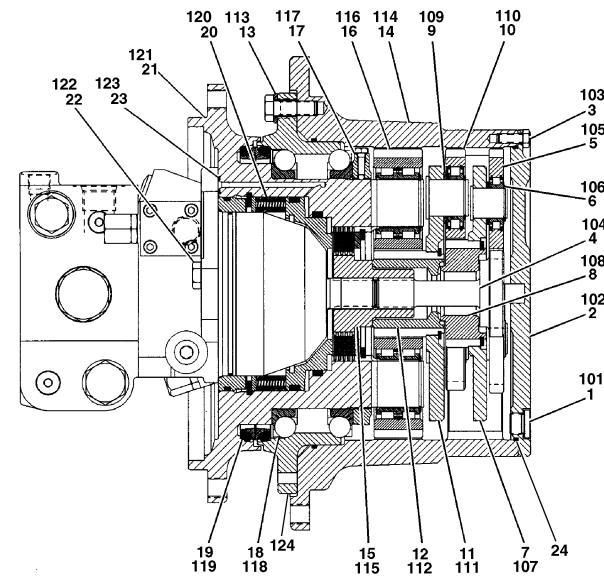
FIGURE 1-5. DRIVE HUB ASSEMBLY |
|
|
|
E |
|
||
|
|
|
|
|
|||
|
|
|
|
|
|
C |
|
FIG & ITEM # |
PART NUMBER |
DESCRIPTION |
QTY. |
REV. |
|
|
|
|
|
|
|
|
|
T |
|
|
7022678 |
DRIVE HUB ASSEMBLY (PRIOR TO S/N 0300067081) |
Ref. |
|
|
|
|
1 |
7022692 |
Drain Plug Kit |
2 |
|
|
I |
|
|
|
O |
|
||||
2 |
7022693 |
Cover Assembly |
1 |
|
|
|
|
3 |
7022694 |
Cover Fastener Kit |
1 |
|
|
N |
|
|
|
|
|
||||
4 |
7022703 |
Shaft, Sun Gear |
1 |
|
|
|
|
5 |
7022670 |
Planet Gear Kit |
1 |
|
|
1 |
|
6 |
7022671 |
Disc, Support |
3 |
|
|
|
|
7 |
7022704 |
Planet Carrier Kit |
1 |
|
|
|
|
8 |
7022705 |
Sun Gear Kit |
1 |
|
|
F |
|
9 |
7022669 |
Disc, Support |
3 |
|
|
|
|
10 |
7022668 |
Planet Gear Kit |
1 |
|
|
R |
|
11 |
7022706 |
Planet Carrier Kit |
1 |
|
|
A |
|
|
|
|
|
||||
12 |
7022707 |
Sun Gear Kit |
1 |
|
|
M |
|
13 |
7022695 |
Gear Fastener Kit |
1 |
|
|
|
|
14 |
7022696 |
Gear, Ring |
1 |
|
|
E |
|
|
|
|
|
||||
15 |
7022697 |
Link, Shaft |
1 |
|
|
|
|
16 |
7022698 |
Gear Kit |
1 |
|
|
|
|
17 |
7022699 |
Shaft Nut Kit |
1 |
|
|
|
|
|
|
|
|
||||
18 |
7022700 |
Bearing Kit |
1 |
|
|
|
|
19 |
7022701 |
Duo Cone Seal Kit |
1 |
|
|
|
|
20 |
7022719 |
Brake Kit |
1 |
|
|
|
|
21 |
7022702 |
Spindle |
1 |
|
|
|
|
22 |
7022640 |
Bolt M12 x 25mm |
2 |
|
|
|
|
23 |
7022646 |
O-Ring |
1 |
|
|
|
|
24 |
7024972 |
O-Ring |
1 |
|
|
|
|
|
7022737 |
DRIVE HUB ASSEMBLY (S/N 0300067081 TO |
Ref. |
|
|
|
|
|
|
S/N 0300128000) |
|
|
|
|
|
101 |
7022692 |
Drain Plug Kit |
2 |
|
|
|
|
102 |
7022738 |
Cover Assembly |
1 |
|
|
|
|
103 |
7022694 |
Cover Fastener Kit |
1 |
|
|
|
|
104 |
7022739 |
Shaft, Sun Gear |
1 |
|
|
|
|
105 |
7022740 |
Planet Gear Kit |
1 |
|
|
|
|
106 |
7022671 |
Disc, Support |
3 |
|
|
|
|
107 |
7022741 |
Planet Carrier Kit |
1 |
|
|
|
|
108 |
7022742 |
Sun Gear Kit |
1 |
|
|
|
|
109 |
7022671 |
Disc, Support |
3 |
|
|
|
|
110 |
7022743 |
Planet Gear Kit |
1 |
|
|
|
|
111 |
7022744 |
Planet Carrier Kit |
1 |
|
|
|
|
112 |
7022745 |
Sun Gear Kit |
1 |
|
|
|
|
113 |
7022695 |
Gear Fastener Kit |
1 |
|
|
|
|
114 |
7022746 |
Gear, Ring |
1 |
|
|
|
|
115 |
7022697 |
Link, Shaft |
1 |
|
|
|
|
116 |
7022747 |
Gear Kit |
1 |
|
|
|
|
117 |
70002816 |
Shaft Nut Kit |
1 |
|
|
|
|
118 |
7022748 |
Bearing Kit |
1 |
|
|
|
|
|
|
|
|
|
|
|
|
3120795 |
1-11 |
|
|
|
|
|
SECTION 1 FRAME |
|
|
|
S |
|
FIGURE 1-5. DRIVE HUB ASSEMBLY (CONTINUED) |
|
|
||
|
E |
|
|
|
|
|
|
|
C |
|
FIG & ITEM # |
PART NUMBER |
DESCRIPTION |
QTY. |
REV. |
|
|
|
|||||
|
|
|
|
|
|
|
|
|
T |
|
119 |
70002817 |
Duo Cone Seal Kit |
1 |
|
|
|
120 |
7022719 |
Brake Kit |
1 |
|
|
|
I |
|
121 |
7022749 |
Spindle |
1 |
|
|
O |
|
122 |
7022640 |
Bolt M12 x 25mm |
2 |
|
|
|
|
|
||||
|
N |
|
123 |
7022646 |
O-Ring |
1 |
|
|
|
124 |
7022750 |
Ring, Support |
1 |
|
|
|
1 |
|
|
|
|
|
|
|
F |
|
|
|
|
|
|
|
R |
|
|
|
|
|
|
|
A |
|
|
|
|
|
|
|
M |
|
|
|
|
|
|
|
E |
|
|
|
|
|
|
|
|
|
|
|
|
|
|
|
|
|
|
|
|
|
|
1-12 |
3120795 |
|
|
SECTION 1 FRAME |
|
|
|
S |
|
FIGURE 1-5. DRIVE HUB ASSEMBLY (CONTINUED) |
|
|
|
|
|||
|
|
|
|
|
|
E |
|
FIG & ITEM # |
PART NUMBER |
DESCRIPTION |
QTY. |
REV. |
|
C |
|
|
|
|
|||||
|
|
|
|
|
|
T |
|
|
|
|
|
|
|
|
|
|
|
|
|
|
|
I |
|
|
|
|
|
|
|
O |
|
|
|
|
|
|
|
N |
|
|
|
|
|
|
|
1 |
|
|
|
|
|
|
|
F |
|
|
|
|
|
|
|
R |
|
|
|
|
|
|
|
A |
|
|
|
|
|
|
|
M |
|
|
|
|
|
|
|
E |
|
|
|
|
|
|
|
|
|
|
|
|
|
|
|
|
|
3120795 |
1-13 |

|
SECTION 1 FRAME |
S |
FIGURE 1-6. DRIVE VALVE ASSEMBLY |
E |
|
C |
|
T |
|
I |
|
O |
|
N |
|
1 |
|
F |
|
R |
|
A |
|
M |
|
E |
|
|
|
1-14 |
3120795 |
|
|
SECTION 1 FRAME |
|
|
|
S |
|
. |
|
|
|
|
|
|
|
FIGURE 1-6. DRIVE VALVE ASSEMBLY |
|
|
|
E |
|
||
|
|
|
|
|
|||
|
|
|
|
|
|
C |
|
FIG & ITEM # |
PART NUMBER |
DESCRIPTION |
QTY. |
REV. |
|
|
|
|
|
|
|
|
|
T |
|
|
7022715 |
DRIVE VALVE ASSEMBLY |
Ref. |
|
|
|
|
1 |
7022685 |
Port Plate Assembly |
1 |
|
|
I |
|
|
|
O |
|
||||
|
7022684 |
Seal Kit - 7022685 Port Plate |
1 |
|
|
|
|
2 |
Not Used |
|
|
|
|
N |
|
|
|
|
|
|
|
||
3 |
7022686 |
Cartridge, Valve (Drive) |
1 |
|
|
|
|
4 |
7022687 |
Cartridge, Valve (Relief) |
2 |
|
|
1 |
|
5 |
7022688 |
Cartridge, Valve (Check) |
2 |
|
|
|
|
6 |
7022689 |
Cartridge, Valve (Selector) |
1 |
|
|
|
|
7 |
7022690 |
Cartridge, Valve (Adapter) |
1 |
|
|
F |
|
8 |
7022691 |
Cartridge, Valve (Brake) |
1 |
|
|
|
|
9 |
7022628 |
Bolt M12 x 100mm |
4 |
|
|
R |
|
|
|
|
|
|
|
A |
|
|
|
|
|
|
|
M |
|
|
|
|
|
|
|
E |
|
|
|
|
|
|
|
|
|
|
|
|
|
|
|
|
|
3120795 |
1-15 |

|
SECTION 1 FRAME |
S |
FIGURE 1-7. ROLLER ASSEMBLIES INSTALLATION |
E |
|
C |
|
T |
|
I |
|
O |
|
N |
|
1
F
R
A
M
E
1-16 |
3120795 |
|
|
SECTION 1 FRAME |
|
|
|
S |
|
. |
|
|
|
|
|
|
|
FIGURE 1-7. ROLLER ASSEMBLIES INSTALLATION |
|
|
|
E |
|
||
|
|
|
|
|
|||
|
|
|
|
|
|
C |
|
FIG & ITEM # |
PART NUMBER |
DESCRIPTION |
QTY. |
REV. |
|
|
|
|
|
|
|
|
|
T |
|
|
|
ROLLER ASSEMBLIES INSTALLATION |
Ref. |
|
|
|
|
1 |
7022645 |
Bolt M24 x 80mm |
4 |
|
|
I |
|
|
|
O |
|
||||
2 |
7022604 |
Roller Assembly - Upper (See Items 101-110 for Breakdown) |
4 |
|
|
|
|
3 |
7022709 |
Roller Assembly - Lower (See Items 201-210 for Breakdown) |
14 |
|
|
N |
|
|
|
|
|
||||
4 |
7022629 |
Bolt M16 x 80mm |
56 |
|
|
|
|
5 |
7022638 |
Washer |
56 |
|
|
1 |
|
|
7022604 |
ROLLER ASSEMBLY - UPPER |
Ref. |
|
|
|
|
|
|
|
|
|
|||
101 |
7022632 |
Shaft |
1 |
|
|
F |
|
102 |
7022662 |
Seal Kit |
1 |
|
|
R |
|
103 |
Not Used |
|
|
|
|
A |
|
|
|
|
|
|
|
||
104 |
7022630 |
Roller & Bearing Assembly |
1 |
|
|
M |
|
105 |
See Note |
Bearing (Note: Not Available for Purchase.) |
2 |
|
|
|
|
106 |
7022633 |
Retainer |
1 |
|
|
E |
|
|
|
|
|
||||
107 |
7022625 |
O-Ring |
1 |
|
|
|
|
108 |
7022637 |
Bolt, Socket Head M10 x 25mm |
5 |
|
|
|
|
109 |
7022631 |
Cover, Carrier Roller |
1 |
|
|
|
|
|
|
|
|
||||
110 |
7022627 |
Plug, Pipe |
1 |
|
|
|
|
|
7022709 |
ROLLER ASSEMBLY - LOWER |
Ref. |
|
|
|
|
201 |
7022619 |
Retainer |
1 |
|
|
|
|
202 |
7022627 |
Plug, Pipe |
1 |
|
|
|
|
203 |
7022611 |
Collar |
2 |
|
|
|
|
204 |
7022618 |
Roller & Bearing Assembly |
1 |
|
|
|
|
205 |
See Note |
Bearing (Note: Not Available for Purchase.) |
2 |
|
|
|
|
206 |
7022663 |
Seal Kit |
2 |
|
|
|
|
207 |
Not Used |
|
|
|
|
|
|
208 |
See Note |
Shaft (Note: Not Available for Purchase.) |
1 |
|
|
|
|
209 |
7022623 |
Dowel |
1 |
|
|
|
|
210 |
7022626 |
O-Ring |
2 |
|
|
|
|
|
|
|
|
|
|
|
|
3120795 |
1-17 |
|
SECTION 1 FRAME |
S |
FIGURE 1-8. IDLER ASSEMBLY |
E |
|
C |
|
T |
|
I |
|
O |
|
N |
|
1 |
|
F |
|
R |
|
A |
|
M |
|
E |
|
|
|
1-18 |
3120795 |
|
|
SECTION 1 FRAME |
|
|
|
S |
|
. |
|
|
|
|
|
|
|
FIGURE 1-8. IDLER ASSEMBLY |
|
|
|
E |
|
||
|
|
|
|
|
|||
|
|
|
|
|
|
C |
|
FIG & ITEM # |
PART NUMBER |
DESCRIPTION |
QTY. |
REV. |
|
|
|
|
|
|
|
|
|
T |
|
|
|
IDLER ASSEMBLY |
Ref. |
|
|
|
|
1 |
7022639 |
Bolt M21 x 40mm |
4 |
|
|
I |
|
|
|
O |
|
||||
2 |
See Note |
Washer, Hardened (Note: Not Available - Purchase |
4 |
|
|
|
|
|
|
Locally.) |
|
|
|
N |
|
|
|
|
|
|
|
|
|
3 |
See Note |
Track Adjuster Assembly (See Figure 1-9 for Breakdown) |
2 |
|
|
|
|
|
|
(Note: Not Available - Purchase Complete Assembly) |
|
|
|
1 |
|
4 |
See Note |
Idler Assembly (See Items 101-103 for Breakdown) |
2 |
|
|
|
|
|
|
|
|
||||
|
|
(Note: Not Available - Purchase Complete Assembly) |
|
|
|
|
|
|
|
IDLER ASSEMBLY |
Ref. |
|
|
F |
|
101 |
See Note |
Recoil Spring Assembly (See Items 201-206 for Breakdown) |
1 |
|
|
R |
|
|
|
(Note: Not Available - Purchase Complete Assembly) |
|
|
|
A |
|
102 |
7022639 |
Bolt M16 x 50mm |
4 |
|
|
M |
|
|
|
|
|
||||
103 |
See Note |
Idler Wheel Assembly (See Items 301-308 for Breakdown) |
1 |
|
|
E |
|
|
|
(Note: Not Available - Purchase Complete Assembly) |
|
|
|
|
|
|
|
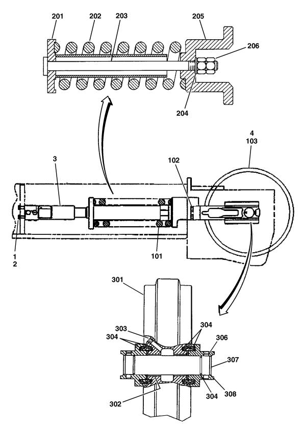
RECOIL SPRING ASSEMBLY |
Ref. |
|
|
|
|
201 |
7022649 |
Support |
1 |
|
|
|
|
202 |
7022659 |
Spring |
1 |
|
|
|
|
203 |
7022621 |
Rod |
1 |
|
|
|
|
204 |
7022648 |
Washer |
1 |
|
|
|
|
205 |
7022620 |
Support |
1 |
|
|
|
|
206 |
7022635 |
Nut M30 |
2 |
|
|
|
|
|
|
IDLER WHEEL ASSEMBLY |
Ref. |
|
|
|
|
301 |
7022624 |
Idler Wheel & Bearing Assembly |
1 |
|
|
|
|
302 |
See Note |
Bearing (Note: Not Available for Purchase.) |
2 |
|
|
|
|
303 |
7022627 |
Plug, Pipe |
1 |
|
|
|
|
304 |
7022657 |
Seal Kit (1 Kit Includes 2 Seals & 1 O-Ring) |
2 |
|
|
|
|
305 |
Not Used |
|
|
|
|
|
|
306 |
7022658 |
Pin |
2 |
|
|
|
|
307 |
7022622 |
Shaft, Idler Wheel |
1 |
|
|
|
|
308 |
7022610 |
Bearing |
2 |
|
|
|
|
|
|
|
|
|
|
|
|
3120795 |
1-19 |

|
SECTION 1 FRAME |
S |
FIGURE 1-9. TRACK ADJUSTER ASSEMBLY |
E |
|
C |
|
T |
|
I |
|
O |
|
N |
|
1 |
|
F |
|
R |
|
A |
|
M |
|
E |
|
|
|
1-20 |
3120795 |
|
|
SECTION 1 FRAME |
|
|
|
S |
|
. |
|
|
|
|
|
|
|
FIGURE 1-9. TRACK ADJUSTER ASSEMBLY |
|
|
|
E |
|
||
|
|
|
|
|
|||
|
|
|
|
|
|
C |
|
FIG & ITEM # |
PART NUMBER |
DESCRIPTION |
QTY. |
REV. |
|
|
|
|
|
|
|
|
|
T |
|
|
|
TRACK ADJUSTER ASSEMBLY |
Ref. |
|
|
|
|
1 |
7022601 |
Cartridge, Valve (Relief) |
1 |
|
|
I |
|
|
|
O |
|
||||
2 |
7022655 |
Cartridge, Valve (Fill) |
1 |
|
|
|
|
3 |
7022665 |
Plate Assembly |
1 |
|
|
N |
|
|
|
|
|
||||
4 |
See Note |
Screw, Drive (Note: Not Available for Purchase.) |
4 |
|
|
|
|
5 |
See Note |
Plate, Warning (Note: Not Available for Purchase.) |
1 |
|
|
1 |
|
6 |
7022600 |
Barrel, Cylinder |
1 |
|
|
|
|
7 |
7022650 |
Piston |
1 |
|
|
|
|
8 |
7022656 |
Seal, Lip |
1 |
|
|
F |
|
9 |
7022660 |
Ring, Back-up |
2 |
|
|
|
|
10 |
7022661 |
Ring, Back-up |
2 |
|
|
R |
|
11 |
7022653 |
O-Ring |
2 |
|
|
A |
|
|
|
|
|
||||
12 |
7022642 |
Bolt M8 x 12mm |
2 |
|
|
M |
|
|
|
|
|
|
|
|
|
|
|
|
|
|
|
E |
|
|
|
|
|
|
|
|
|
|
|
|
|
|
|
|
|
3120795 |
1-21 |
|
|
|
|
|
SECTION 1 FRAME |
|
|
|
S |
|
FIGURE 1-9. TRACK ADJUSTER ASSEMBLY (CONTINUED) |
|
|
||
|
E |
|
|
|
|
|
|
|
C |
|
FIG & ITEM # |
PART NUMBER |
DESCRIPTION |
QTY. |
REV. |
|
|
|
|||||
|
T |
|
|
|
|
|
|
|
|
|
|
|
|
|
|
|
I |
|
|
|
|
|
|
|
O |
|
|
|
|
|
|
|
N |
|
|
|
|
|
|
|
1 |
|
|
|
|
|
|
|
F |
|
|
|
|
|
|
|
R |
|
|
|
|
|
|
|
A |
|
|
|
|
|
|
|
M |
|
|
|
|
|
|
|
E |
|
|
|
|
|
|
|
|
|
|
|
|
|
|
|
|
|
|
|
|
|
|
1-22 |
3120795 |

SECTION 2 3 TURNTABLE
TABLE OF CONTENTS
FIGURE |
DESCRIPTION |
PAGE |
|
|
|
2-1 |
CONTROL VALVES INSTALLATIONS . . . . . . . . . . . . . . . . . . . . . . . . . . . . . . . . . . . . . . . . . |
. 2-2. . |
2-2 |
MAIN CONTROL VALVE ASSEMBLY. . . . . . . . . . . . . . . . . . . . . . . . . . . . . . . . . . . . . . . . . . |
. 2-6. . |
2-3 |
ARTICULATING JIB VALVE ASSEMBLY . . . . . . . . . . . . . . . . . . . . . . . . . . . . . . . . . . . . . . . |
. 2-10. . |
2-4 |
SWING DRIVE, TURNTABLE BEARING & LOCK INSTALLATIONS . . . . . . . . . . . . . . . . . |
. 2-12. . |
2-5 |
SWING HUB ASSEMBLY . . . . . . . . . . . . . . . . . . . . . . . . . . . . . . . . . . . . . . . . . . . . . . . . . . |
. 2-16. . |
2-6 |
SWING BRAKE ASSEMBLY . . . . . . . . . . . . . . . . . . . . . . . . . . . . . . . . . . . . . . . . . . . . . . . . |
. 2-18. . |
2-7 |
SWING MOTOR ASSEMBLY (WHITE ROLLER STATOR) . . . . . . . . . . . . . . . . . . . . . . . . . . |
. 2-22. . |
2-8 |
SWING MOTOR ASSEMBLY (PARKER) . . . . . . . . . . . . . . . . . . . . . . . . . . . . . . . . . . . . . . . |
. 2-24. . |
2-9 |
DEUTZ ENGINE INSTALLATION . . . . . . . . . . . . . . . . . . . . . . . . . . . . . . . . . . . . . . . . . . . . . |
. 2-26. . |
2-10 |
GENERATOR INSTALLATION - DEUTZ MACHINES (OPTIONAL) . . . . . . . . . . . . . . . . . . |
2-32. . . |
2-11 |
PISTON PUMP ASSEMBLY . . . . . . . . . . . . . . . . . . . . . . . . . . . . . . . . . . . . . . . . . . . . . . . . . |
. 2-36. . |
2-12 |
GEAR PUMP ASSEMBLY. . . . . . . . . . . . . . . . . . . . . . . . . . . . . . . . . . . . . . . . . . . . . . . . . . . |
. 2-42. . |
2-13 |
TANK INSTALLATIONS. . . . . . . . . . . . . . . . . . . . . . . . . . . . . . . . . . . . . . . . . . . . . . . . . . . . . |
. 2-44. . |
2-14 |
ROTARY COUPLING INSTALLATION . . . . . . . . . . . . . . . . . . . . . . . . . . . . . . . . . . . . . . . . . |
. 2-46. . |
2-15 |
GROUND CONTROL BOX ASSEMBLY . . . . . . . . . . . . . . . . . . . . . . . . . . . . . . . . . . . . . . . . |
. 2-48. . |
2-16 |
ELECTRICAL OPTIONS INSTALLATION (TURNTABLE MOUNTED) . . . . . . . . . . . . . . . . . |
. 2-52. . |
2-17 |
ENGINE TRAY JACK INSTALLATION (OPTIONAL). . . . . . . . . . . . . . . . . . . . . . . . . . . . . . . |
2-56. . . |
2-18 |
HOODS & LIFTING PLATE INSTALLATIONS . . . . . . . . . . . . . . . . . . . . . . . . . . . . . . . . . . . |
. 2-58. . |
S E C T I O N
2
T U R N T A B L E
3120795 |
2-1 |

SECTION 2 3 TURNTABLE
FIGURE 2-1. CONTROL VALVES INSTALLATIONS
S
E
C
T
I
O
N
2
T
U
R
N
T
A
B
L
E
2-2 |
3120795 |
Loading...