


JLG 4017 Service Manual

An Oshkosh Corporation Company
Model
4017
3121858
Revised
September 3, 2010
Service Manual


EFFECTIV IT Y PAGE
June 10, 2005 - A - Original Issue Of Manual
January 6, 2006 - B - Revision Of Manual
September 3, 2010 - C - Revised pages 2.8, 3.25 thru 3.27, 6.5 & 6.6
31261858 4017 i

EFFECTIV IT Y PAGE
4017 3121858-ii

SECTION CONTENTS
Section Subject Page
Section 1
Safety Practices . . . . . . . . . . . . . . . . . . . . . . . . . . . . . . . . . . . . . . . . . . . . . . . . . . . . . . . 1.1
1.1 Introduction . . . . . . . . . . . . . . . . . . . . . . . . . . . . . . . . . . . . . . . . . . . . . . . . . . . . . . . . . . 1.2
1.2 Disclaimer . . . . . . . . . . . . . . . . . . . . . . . . . . . . . . . . . . . . . . . . . . . . . . . . . . . . . . . . . . . 1.2
1.3 Operator & Safety Manual . . . . . . . . . . . . . . . . . . . . . . . . . . . . . . . . . . . . . . . . . . . . . . . 1.2
1.4 Accident Prevention Tags . . . . . . . . . . . . . . . . . . . . . . . . . . . . . . . . . . . . . . . . . . . . . . . 1.2
1.5 Safety Information . . . . . . . . . . . . . . . . . . . . . . . . . . . . . . . . . . . . . . . . . . . . . . . . . . . . . 1.3
1.6 Safety Instructions . . . . . . . . . . . . . . . . . . . . . . . . . . . . . . . . . . . . . . . . . . . . . . . . . . . . . 1.3
1.7 Emergency Exit Rear Window. . . . . . . . . . . . . . . . . . . . . . . . . . . . . . . . . . . . . . . . . . . . 1.5
1.8 Safety Decals. . . . . . . . . . . . . . . . . . . . . . . . . . . . . . . . . . . . . . . . . . . . . . . . . . . . . . . . . 1.5
Section 2
General Information and Specifications . . . . . . . . . . . . . . . . . . . . . . . . . . . . . . . . . . . . 2.1
2.1 Replacement Parts and Warranty Information. . . . . . . . . . . . . . . . . . . . . . . . . . . . . . . . 2.2
2.2 Torques . . . . . . . . . . . . . . . . . . . . . . . . . . . . . . . . . . . . . . . . . . . . . . . . . . . . . . . . . . . . . 2.3
2.3 Specifications. . . . . . . . . . . . . . . . . . . . . . . . . . . . . . . . . . . . . . . . . . . . . . . . . . . . . . . . . 2.6
2.4 Fluids, Lubricants and Capacities . . . . . . . . . . . . . . . . . . . . . . . . . . . . . . . . . . . . . . . . . 2.9
2.5 Service and Maintenance Schedules. . . . . . . . . . . . . . . . . . . . . . . . . . . . . . . . . . . . . . . 2.10
2.6 Lubrication Schedules . . . . . . . . . . . . . . . . . . . . . . . . . . . . . . . . . . . . . . . . . . . . . . . . . . 2.11
Section 3
Boom . . . . . . . . . . . . . . . . . . . . . . . . . . . . . . . . . . . . . . . . . . . . . . . . . . . . . . . . . . . 3.1
3.1 Boom System Component Terminology. . . . . . . . . . . . . . . . . . . . . . . . . . . . . . . . . . . . . 3.2
3.2 Boom System . . . . . . . . . . . . . . . . . . . . . . . . . . . . . . . . . . . . . . . . . . . . . . . . . . . . . . . . 3.3
3.3 Boom Assembly Maintenance . . . . . . . . . . . . . . . . . . . . . . . . . . . . . . . . . . . . . . . . . . . . 3.3
3.4 Boom Extend and Retract Chains . . . . . . . . . . . . . . . . . . . . . . . . . . . . . . . . . . . . . . . . . 3.14
3.5 Boom Section Separation Adjustment . . . . . . . . . . . . . . . . . . . . . . . . . . . . . . . . . . . . . . 3.17
3.6 Hose Carrier Assembly . . . . . . . . . . . . . . . . . . . . . . . . . . . . . . . . . . . . . . . . . . . . . . . . . 3.18
3.7 Boom Wear Pads. . . . . . . . . . . . . . . . . . . . . . . . . . . . . . . . . . . . . . . . . . . . . . . . . . . . . . 3.21
3.8 Quick Switch Assembly . . . . . . . . . . . . . . . . . . . . . . . . . . . . . . . . . . . . . . . . . . . . . . . . . 3.23
3.9 Troubleshooting . . . . . . . . . . . . . . . . . . . . . . . . . . . . . . . . . . . . . . . . . . . . . . . . . . . . . . . 3.25
Section 4
Cab and Covers . . . . . . . . . . . . . . . . . . . . . . . . . . . . . . . . . . . . . . . . . . . . . . . . . . . . . . . . 4.1
4.1 Operator’s Cab and Covers Component Terminology. . . . . . . . . . . . . . . . . . . . . . . . . . 4.2
4.2 Operator’s Cab. . . . . . . . . . . . . . . . . . . . . . . . . . . . . . . . . . . . . . . . . . . . . . . . . . . . . . . .4.3
4.3 Cab Components. . . . . . . . . . . . . . . . . . . . . . . . . . . . . . . . . . . . . . . . . . . . . . . . . . . . . . 4.3
4.4 Cab Removal . . . . . . . . . . . . . . . . . . . . . . . . . . . . . . . . . . . . . . . . . . . . . . . . . . . . . . . . . 4.7
4.5 Cab Installation . . . . . . . . . . . . . . . . . . . . . . . . . . . . . . . . . . . . . . . . . . . . . . . . . . . . . . . 4.8
Section 5
Axles, Drive Shafts, Wheels and Tires . . . . . . . . . . . . . . . . . . . . . . . . . . . . . . . . . . . . . 5.1
5.1 Axle, Drive Shaft and Wheel Component Terminology . . . . . . . . . . . . . . . . . . . . . . . . . 5.2
5.2 General Information . . . . . . . . . . . . . . . . . . . . . . . . . . . . . . . . . . . . . . . . . . . . . . . . . . . . 5.3
5.3 Axle Assemblies. . . . . . . . . . . . . . . . . . . . . . . . . . . . . . . . . . . . . . . . . . . . . . . . . . . . . . . 5.3
5.4 Drive Shafts . . . . . . . . . . . . . . . . . . . . . . . . . . . . . . . . . . . . . . . . . . . . . . . . . . . . . . . . . . 5.10
5.5 Wheels and Tires . . . . . . . . . . . . . . . . . . . . . . . . . . . . . . . . . . . . . . . . . . . . . . . . . . . . . . 5.12
5.6 Brakes . . . . . . . . . . . . . . . . . . . . . . . . . . . . . . . . . . . . . . . . . . . . . . . . . . . . . . . . . . . . . . 5.13
5.7 Towing a Disabled machine . . . . . . . . . . . . . . . . . . . . . . . . . . . . . . . . . . . . . . . . . . . . . . 5.14
4017
JLG Industries, Inc.
i

Section Subject Page
Section 6
Transmission: . . . . . . . . . . . . . . . . . . . . . . . . . . . . . . . . . . . . . . . . . . . . . . . . . . . . . . . . .6.1
6.1 Transmission Assembly Component Terminology . . . . . . . . . . . . . . . . . . . . . . . . . . . . . 6.2
6.2 Transmission Description. . . . . . . . . . . . . . . . . . . . . . . . . . . . . . . . . . . . . . . . . . . . . . . . 6.3
6.3 Transmission Serial Number . . . . . . . . . . . . . . . . . . . . . . . . . . . . . . . . . . . . . . . . . . . . . 6.3
6.4 Transmission Specifications. . . . . . . . . . . . . . . . . . . . . . . . . . . . . . . . . . . . . . . . . . . . . . 6.3
6.5 Transmission Maintenance . . . . . . . . . . . . . . . . . . . . . . . . . . . . . . . . . . . . . . . . . . . . . . 6.3
6.6 Transmission Replacement . . . . . . . . . . . . . . . . . . . . . . . . . . . . . . . . . . . . . . . . . . . . . . 6.3
6.7 Troubleshooting . . . . . . . . . . . . . . . . . . . . . . . . . . . . . . . . . . . . . . . . . . . . . . . . . . . . . . . 6.7
Section 7
Engine: Perkins 1004-40T . . . . . . . . . . . . . . . . . . . . . . . . . . . . . . . . . . . . . . . . . . . . . . . . 7.1
7.1 Introduction . . . . . . . . . . . . . . . . . . . . . . . . . . . . . . . . . . . . . . . . . . . . . . . . . . . . . . . . . . 7.2
7.2 Engine Serial Number . . . . . . . . . . . . . . . . . . . . . . . . . . . . . . . . . . . . . . . . . . . . . . . . . . 7.4
7.3 Specifications and Maintenance Information . . . . . . . . . . . . . . . . . . . . . . . . . . . . . . . . . 7.4
7.4 Engine Cooling System . . . . . . . . . . . . . . . . . . . . . . . . . . . . . . . . . . . . . . . . . . . . . . . . . 7.4
7.5 Engine Electrical System . . . . . . . . . . . . . . . . . . . . . . . . . . . . . . . . . . . . . . . . . . . . . . . . 7.6
7.6 Fuel System . . . . . . . . . . . . . . . . . . . . . . . . . . . . . . . . . . . . . . . . . . . . . . . . . . . . . . . . . .7.6
7.7 Engine Exhaust System. . . . . . . . . . . . . . . . . . . . . . . . . . . . . . . . . . . . . . . . . . . . . . . . . 7.8
7.8 Air Cleaner Assembly. . . . . . . . . . . . . . . . . . . . . . . . . . . . . . . . . . . . . . . . . . . . . . . . . . . 7.9
7.9 Engine Replacement . . . . . . . . . . . . . . . . . . . . . . . . . . . . . . . . . . . . . . . . . . . . . . . . . . . 7.9
7.10 Engine Drive Plate . . . . . . . . . . . . . . . . . . . . . . . . . . . . . . . . . . . . . . . . . . . . . . . . . . . . . 7.13
7.11 Troubleshooting . . . . . . . . . . . . . . . . . . . . . . . . . . . . . . . . . . . . . . . . . . . . . . . . . . . . . .7.14
Section 8
Hydraulic System . . . . . . . . . . . . . . . . . . . . . . . . . . . . . . . . . . . . . . . . . . . . . . . . . . . . . . . 8.1
8.1 Hydraulic Component Terminology . . . . . . . . . . . . . . . . . . . . . . . . . . . . . . . . . . . . . . . . 8.2
8.2 Safety Information . . . . . . . . . . . . . . . . . . . . . . . . . . . . . . . . . . . . . . . . . . . . . . . . . . . . . 8.3
8.3 Hydraulic Pressure Diagnosis . . . . . . . . . . . . . . . . . . . . . . . . . . . . . . . . . . . . . . . . . . . . 8.3
8.4 Hydraulic Circuits . . . . . . . . . . . . . . . . . . . . . . . . . . . . . . . . . . . . . . . . . . . . . . . . . . . . . .8.4
8.5 Hydraulic Reservoir . . . . . . . . . . . . . . . . . . . . . . . . . . . . . . . . . . . . . . . . . . . . . . . . . . . . 8.7
8.6 Engine Implement Pump . . . . . . . . . . . . . . . . . . . . . . . . . . . . . . . . . . . . . . . . . . . . . . . . 8.8
8.7 Control Valves . . . . . . . . . . . . . . . . . . . . . . . . . . . . . . . . . . . . . . . . . . . . . . . . . . . . . . . .8.10
8.8 Hydraulic Cylinders . . . . . . . . . . . . . . . . . . . . . . . . . . . . . . . . . . . . . . . . . . . . . . . . . . . . 8.16
Section 9
Electrical System . . . . . . . . . . . . . . . . . . . . . . . . . . . . . . . . . . . . . . . . . . . . . . . . . . . . . . . 9.1
9.1 Electrical Component Terminology. . . . . . . . . . . . . . . . . . . . . . . . . . . . . . . . . . . . . . . . . 9.3
9.2 Service Warnings. . . . . . . . . . . . . . . . . . . . . . . . . . . . . . . . . . . . . . . . . . . . . . . . . . . . . . 9.4
9.3 Specifications. . . . . . . . . . . . . . . . . . . . . . . . . . . . . . . . . . . . . . . . . . . . . . . . . . . . . . . . . 9.4
9.4 Fuses and Relays . . . . . . . . . . . . . . . . . . . . . . . . . . . . . . . . . . . . . . . . . . . . . . . . . . . . . 9.4
9.5 Electrical System Schematics . . . . . . . . . . . . . . . . . . . . . . . . . . . . . . . . . . . . . . . . . . . . 9.7
9.6 Circuit Breakdowns . . . . . . . . . . . . . . . . . . . . . . . . . . . . . . . . . . . . . . . . . . . . . . . . . . . . 9.12
9.7 Engine Start Circuit . . . . . . . . . . . . . . . . . . . . . . . . . . . . . . . . . . . . . . . . . . . . . . . . . . . . 9.15
9.8 Charging Circuit . . . . . . . . . . . . . . . . . . . . . . . . . . . . . . . . . . . . . . . . . . . . . . . . . . . . . . .9.16
9.9 Window Wiper/Washer Windshield Wiper Motor . . . . . . . . . . . . . . . . . . . . . . . . . . . . . . 9.17
9.10 Cab Heater and Fan. . . . . . . . . . . . . . . . . . . . . . . . . . . . . . . . . . . . . . . . . . . . . . . . . . . . 9.19
9.11 Solenoids and Senders . . . . . . . . . . . . . . . . . . . . . . . . . . . . . . . . . . . . . . . . . . . . . . . . . 9.20
9.12 Display Monitor and Gauges . . . . . . . . . . . . . . . . . . . . . . . . . . . . . . . . . . . . . . . . . . . . . 9.27
9.13 Joystick . . . . . . . . . . . . . . . . . . . . . . . . . . . . . . . . . . . . . . . . . . . . . . . . . . . . . . . . . . . . . 9.28
9.14 Dash Switches . . . . . . . . . . . . . . . . . . . . . . . . . . . . . . . . . . . . . . . . . . . . . . . . . . . . . . . .9.28
9.15 Transmission Control Lever / Accessory Control Lever. . . . . . . . . . . . . . . . . . . . . . . . . 9.29
ii
4017

Section 1
Safety Practices
Contents
PARAGRAPH TITLE PAGE
1.1 Introduction . . . . . . . . . . . . . . . . . . . . . . . . . . . . . . . . . . . . . . . . . . . . . . . . . . . . . . . 1.2
1.3 Operator & Safety Manual . . . . . . . . . . . . . . . . . . . . . . . . . . . . . . . . . . . . . . . . . . . 1.2
1.4 Accident Prevention Tags . . . . . . . . . . . . . . . . . . . . . . . . . . . . . . . . . . . . . . . . . . . 1.2
1.5 Safety Information. . . . . . . . . . . . . . . . . . . . . . . . . . . . . . . . . . . . . . . . . . . . . . . . . . 1.3
1.5.1 Safety Alert System and Signal Words. . . . . . . . . . . . . . . . . . . . . . . . . . . 1.3
1.6 Safety Instructions . . . . . . . . . . . . . . . . . . . . . . . . . . . . . . . . . . . . . . . . . . . . . . . . . 1.3
1.6.1 Personal Hazards . . . . . . . . . . . . . . . . . . . . . . . . . . . . . . . . . . . . . . . . . . . 1.3
1.6.2 Equipment Hazards. . . . . . . . . . . . . . . . . . . . . . . . . . . . . . . . . . . . . . . . . . 1.3
1.6.4 Operational Hazards . . . . . . . . . . . . . . . . . . . . . . . . . . . . . . . . . . . . . . . . . 1.4
1.7 Emergency Exit Rear Window . . . . . . . . . . . . . . . . . . . . . . . . . . . . . . . . . . . . . . . . 1.5
1.8 Safety Decals. . . . . . . . . . . . . . . . . . . . . . . . . . . . . . . . . . . . . . . . . . . . . . . . . . . . . . 1.5
4017
1.1

Safety Practices
1.1 INTRODUCTION
This service manual provides general directions for
accomplishing servic e and re pai r proc edu res. Fo ll owi ng
the procedures in this manual will help assure safety and
equipment reliability.
Read, understand and follow the information in this
manual, and obey all locally appro ved safe ty p r actices,
procedures, rules, codes, regulations and laws.
These instructions cannot cover all details or variations in
the equipment, procedures, or processes described, nor
provide directions for meeting every possible contingency
during opera tion, maintenance, or testing. When additi onal
information is desired consult the local JLG distributor.
Many factors contribute to unsafe conditions: carelessness,
fatigue, overload, inattentiveness, unfamiliarity, even
drugs and alcohol, among others. For optimal safety,
encourage everyone to think, and to act, safely.
Appropriate service methods and proper repair
procedures are essential for the safety of the individual
doing the work, for the safety of the operator, and for the
safe, reliable operation of the machine. All references to
the right side, left side, front and rear are given from the
operator’s seat looking in a for ward direction.
Supplementary information is available from JLG in the
form of Service Bulletins, Service Campaigns, Service
Training Schools, the JLG website, other literature, and
through updates to the manual itself.
1.2 DISCLAIMER
All information in this manual is based on the latest
product information available at the time of publication.
JLG reserves the right to make changes and
improvements to its products, and to discontinue the
manufacture of any product, at its discretion at any time
without public notice or obligation.
1.3 OPERATOR & SAFETY MANUAL
The mechanic must not operate the machine until the
Operator & Safety Manual has been read & understood,
training has been accomplished and operation of the
machine has been completed under the supervision of an
experienced and qualified operator.
An Operator & Safety Manual is supplied with each
machine and must be kept in the cab. In the event that the
Operator & Safety Manual is missing, consult the local
JLG distributor before proceeding.
1.4 ACCIDENT PREVENTION TAGS
Place Accident Prevention Tags on the ignition key
switch and the steering wheel before attempting to
perform any service or maintenance. Remove key and
disconnect battery leads.
1.2
4017
Safety Practices
1.5 SAFETY INFORMATION
To avoid possible death or injury, carefully read,
understand and comply with all safety messages.
In the event of an accident, know where to obtain medical
assistance and how to use a first-aid kit and fire
extinguisher/fire suppression system. Keep emergency
telephone numbers (fire department, ambulance, rescue
squad/paramedics, police department, etc.) nearby. If
working alone, check with another person routinely to
help assure personal safety.
1.5.1 Safety Alert System and Signal Words
DANGER
DANGER indicates an imminently hazardous situation
which, if not avoided, will result in death or serious injury.
WARNING
WARNING indicates a potentially hazardous situation
which, if not avoided, could result in death or serious
injury.
CAUTION
CAUTION indicates a potentially hazardous situation
which, if not avoided, may result in minor or moderate
injury.
1.6 SAFETY INSTRUCTIONS
Following are general safety statements to consider before
performing maintenance procedures on the telehandler.
Additional statements related to specific tasks and
procedures are located throughout this manual and are
listed prior to any work instructions to provide safety
information before the potential of a hazard occurs.
For all safety messages, carefully read, understand and
follow the instructions before
1.6.1 Personal Hazards
PERSONAL SAFETY GEAR: Wear all the protective
clothing and personal safety gear necessary to perform
the job safely. This might include heavy gloves, safety
glasses or goggles, filter mask or respirator, safety shoes
or a hard hat.
LIFTING: NEVER lift a heavy object without the help of at
least one assistant or a suitable sling and hoist.
1.6.2 Equipment Hazards
LIFTING OF EQUIPMENT: Before using any lifting
equipment (chains, slings, brackets, hooks, etc.), verify
that it is of the proper capacity, in good working order, and
is properly attached.
NEVER stand or otherwise become positioned under a
suspended load or under raised equipment. The load or
equipment could fall or tip.
DO NOT use a hoist, jack or jack stands only to support
equipment. Always support equipment with the proper
capacity blocks or stands properly rated for the load.
HAND TOOLS: Always use the proper tool for the job;
keep tools clean and in good working order, and use
special service tools only as recommended.
proceeding.
4017
1.3

Safety Practices
1.6.3 General Hazards
SOLVENTS: Only use approved solvents that are known
to be safe for use.
HOUSEKEEPING: Keep the work area and operator’s
cab clean, and remove all hazards (debris, oil, tools, etc.).
FIRST AID: Imme diately clean, dress and report all inj uries
(cuts, abrasions, burns, etc.), no matter how minor the
injury may seem. Know the location of a First Aid Kit, and
know how to use it.
CLEANLINESS: Wear eye protection, and clean all
components with a high-pressure or steam cleaner
before attempting service.
When removing hydraulic components, plug hose ends
and connections to prevent excess leakage and
contamination. Place a suitable catch basin beneath the
machine to capture fluid run-off.
Check and obey all Federal, State and/or Local
regulations regarding waste storage, disposal and
recycling.
1.6.4 Operational Hazards
ENGINE: Stop the engine before performing any service
unless specificall y instr uc ted othe rw is e.
VENTILATION: Avoid prolonged engine operation in
enclosed areas without adequate ventilation.
SOFT SURFACES AND SLOPES: NEVER work on a
machine that is parked on a soft surface or slope. The
machine must b e on a hard leve l surfa ce, wit h th e wh eel s
blocked before performing any service.
FLUID TEMPERATURE: NEVER work on a machine
when the engine, cooling or hydraulic systems are hot.
Hot components and fluids can cause severe burns.
Allow systems to cool before proceeding.
FLUID PRESSURE: Before loosenin g any hydr aul ic or
diesel fuel component, hose or tube, turn the engine
OFF. Wear heavy, protective gloves and eye protection.
NEVER check for leaks using any part of your body; use
a piece of cardboard or wood instead. If injured, seek
medical attention immediately. Diesel fluid leaking under
pressure can explode. Hydraulic fluid and diesel fuel
leaking under pressure can penetrate the skin, cause
infection, gangrene and other serious personal injury.
Relieve all pressure before disconnecting any
component, part, line or hose. Slowly loosen parts and
allow release of residual pressure before removing any
part or component. Before starting the engine or applying
pressure, use components, parts, hoses and pipes that
are in good condition, connected properly and are
tightened to the proper torque. Capture fluid in an
appropriate container and dispose of in accordance with
prevailing environmental regulations.
RADIATOR CAP: Always wear steam-resistant, heat
protective gloves when opening the radiator cap. Cover
the cap with a clean, thick cloth and turn slowly to the first
stop to relieve pressure.
FLUID FLAMABILTITY: DO NOT service the fuel or
hydraulic systems near an open flame, sparks or smoking
materials.
NEVER drain or store fluids in an open container. Engine
fuel and hydraulic fluid are flammable and can cause a
fire and/or explosion.
DO NOT mix gasoline or alcohol with diesel fuel. The
mixture can cause an explosion.
PRESSURE TESTING: When conducting any test, only
use test equipment that is correctly calibrated and in good
condition. Use the correct equipment in the pr ope r
manner, and make changes or repairs as indicated by the
test procedure to achieve the desired result.
LEAVING MACHINE: Lower the forks or attachment to
the ground before leaving the machine.
TIRES: Always keep tires inflated to the proper pressure
to help prevent tipover. DO NOT over-inflate tires.
NEVER use mismatched tire types, sizes or ply ratings.
Always use matched sets according to machine
specifications.
MAJOR COMPONENTS: Never alter, remove, or
substitute any items such as counterweights, tires,
batteries or other items that may reduce or affect the
overall weight or stability of the machine.
BATTERY: DO NOT charge a frozen battery.Charging a
frozen battery may cause it to explode. Allow the battery
to thaw before jump-starting or connecting a battery
charger.
1.4
4017
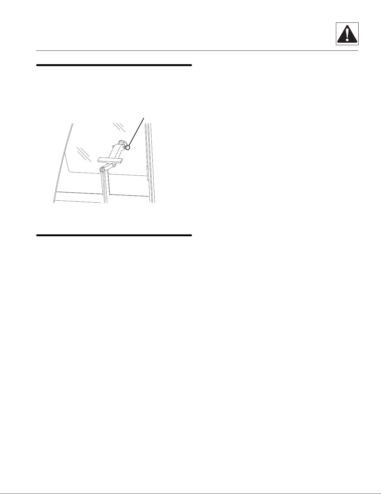
1.7 EMERGENCY EXIT REAR WINDOW
MZ1400
1
The rear window in the enclosed cab can be used as an
emergency exit by removing the latch pin (1) located on
the window latch. Once the latch pin is removed, the
window is free to swing open.
Safety Practices
1.8 SAFETY DECALS
Check that all safety decals are present and readable on
the machine. Refer to the Operator & Safety Manual
supplied with machine for information.
4017
1.5

Safety Practices
This Page Intentionally Left Blank
1.6
4017

Section 2
General Information and Specifications
PARAGRAPH TITLE PAGE
2.1 Replacement Parts and Warranty Information . . . . . . . . . . . . . . . . . . . . . . . . . . . 2.2
2.2 T orques. . . . . . . . . . . . . . . . . . . . . . . . . . . . . . . . . . . . . . . . . . . . . . . . . . . . . . . . . . . 2.3
2.2.1 ASTM Fastener Torque Chart (English) . . . . . . . . . . . . . . . . . . . . . . . . . . 2.3
2.2.2 ASTM Fastener Torque Chart (Metric) . . . . . . . . . . . . . . . . . . . . . . . . . . . 2.4
2.2.3 Metric Fastener Torque Chart . . . . . . . . . . . . . . . . . . . . . . . . . . . . . . . . . . 2.5
2.3 Specifications . . . . . . . . . . . . . . . . . . . . . . . . . . . . . . . . . . . . . . . . . . . . . . . . . . . . . 2.6
2.3.1 Travel Speeds . . . . . . . . . . . . . . . . . . . . . . . . . . . . . . . . . . . . . . . . . . . . . . 2.6
2.3.2 Engine Performance Specifications . . . . . . . . . . . . . . . . . . . . . . . . . . . . . 2.6
2.3.3 Hydraulic Cylinder Performance . . . . . . . . . . . . . . . . . . . . . . . . . . . . . . . . 2.6
2.3.4 Tires. . . . . . . . . . . . . . . . . . . . . . . . . . . . . . . . . . . . . . . . . . . . . . . . . . . . . . 2.7
2.3.5 Axles . . . . . . . . . . . . . . . . . . . . . . . . . . . . . . . . . . . . . . . . . . . . . . . . . . . . . 2.7
2.3.6 Electrical System. . . . . . . . . . . . . . . . . . . . . . . . . . . . . . . . . . . . . . . . . . . . 2.8
2.4 Fluids, Lubricants and Capacities . . . . . . . . . . . . . . . . . . . . . . . . . . . . . . . . . . . . . 2.9
2.5 Service and Maintenance Schedules. . . . . . . . . . . . . . . . . . . . . . . . . . . . . . . . . . . 2.10
2.5.1 8 & 1st 50 Hour Maintenance Schedule . . . . . . . . . . . . . . . . . . . . . . . . . . 2.10
2.5.2 50, 250 & 500 Hour Maintenance Schedule . . . . . . . . . . . . . . . . . . . . . . . 2.10
2.5.3 1000 & 1500 Hour Maintenance Schedule . . . . . . . . . . . . . . . . . . . . . . . . 2.11
2.6 Lubrication Schedules . . . . . . . . . . . . . . . . . . . . . . . . . . . . . . . . . . . . . . . . . . . . . . 2.11
2.6.1 8 Hour Lube Schedule. . . . . . . . . . . . . . . . . . . . . . . . . . . . . . . . . . . . . . . . 2.11
2.6.2 50 Hour Lube Schedule. . . . . . . . . . . . . . . . . . . . . . . . . . . . . . . . . . . . . . . 2.11
4017
2.1
General Information and Specifications
35
MZ1462
1
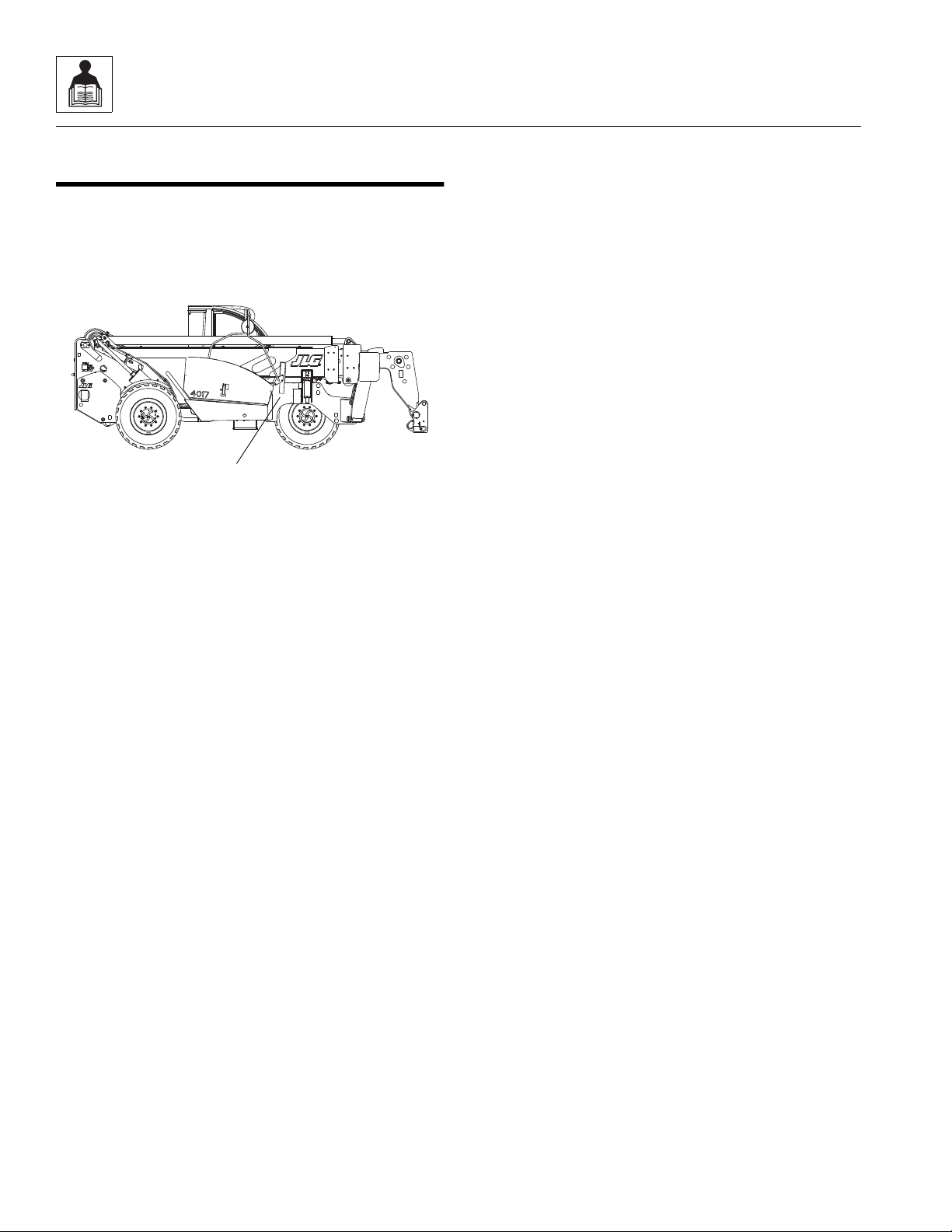
2.1 REPLACEMENT PARTS AND WARRANTY INFORMATION
Before ordering parts or initiating service inquiries, make
note of the machine serial number. The machine serial
number plate (1) is located as indicated in the figure
below.
IMPORTANT: The replacement of any part on this
machine with any other than JLG authorized
replacement parts can adversely affect the performance,
durability, or safety of the machine, and will void the
warranty. JLG disclaims liability for any claims or
damages, whether regarding property damage, personal
injury or death arising out of the use of unauthorized
replacement parts.
A warranty registration form must be filled out by the JLG
distributor, signed by the purchaser and returned to JLG
when the machine is sold and/or put into use.
Registration activates the warranty period and helps to
assure that warranty claims are promptly processed. To
guarantee full warranty service, verify that the distributor
has returned the business reply card of the warranty
registration form to JLG.
2.2
4017
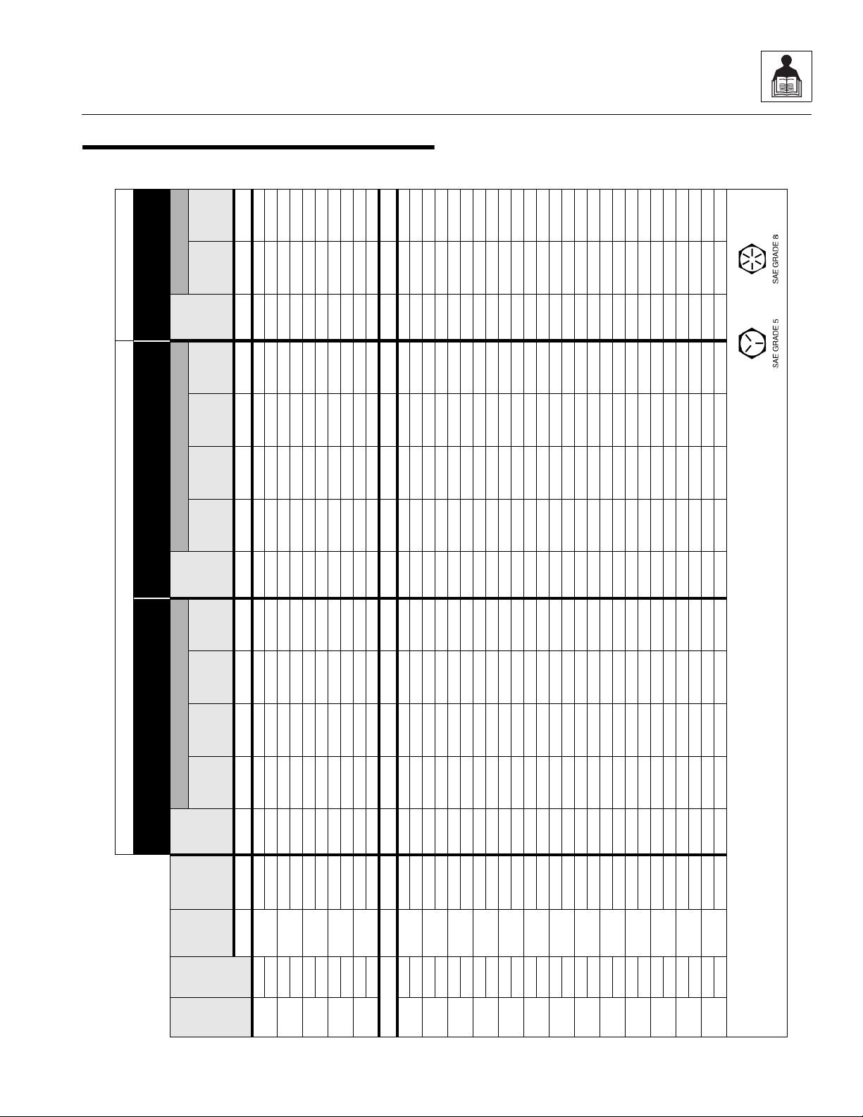
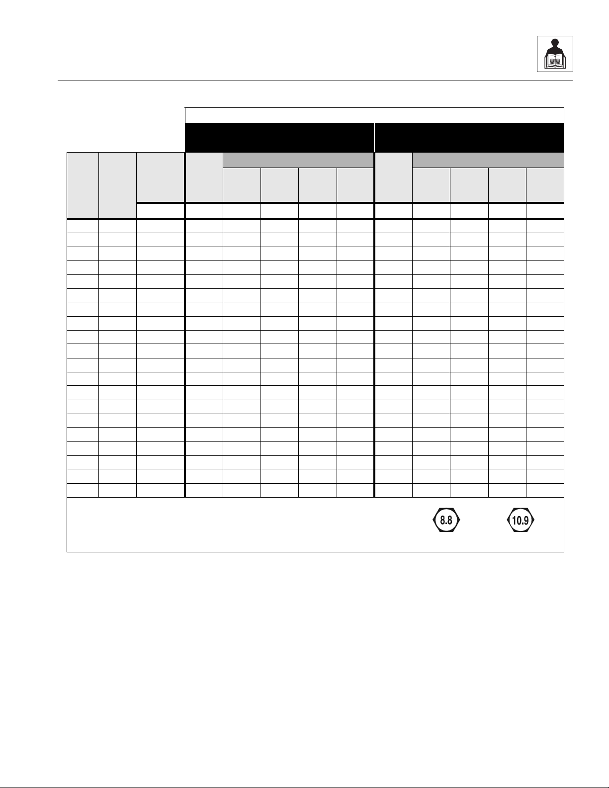
2.2 TORQUES
VALUES FOR ZINC PLATED / YELLOW CHROMATE FASTENERS ONLY UNPLATED CAP SCREWS
SAE GRADE 5 BOLTS &
GRADE 2 NUTS
SAE GRADE 8 BOLTS & GRADE 8 NUTS
& SOCKET HEAD CAP SCREWS
UNBRAKO 1960 SERIES
SOCKET HEAD
SIZE
THDS.
PER
INCH
BOLT
DIA.
TENSILE
STRESS
AREA
CLAMP
LOAD
TORQUE
CLAMP
LOAD
TORQUE
CLAMP
LOAD
TORQUE
DRY OR
LOCTITE
263
LUB
LOCT ITE
262
LOCTITE
242 OR
271
DRY OR
LOCTITE
263
LUB
LOCTITE
262
LOCTITE
242 OR
271
WITHOUT
LOC-WEL
PATCH
WITH
LOC-WEL
PATCH
IN SQ. IN. LB. IN-LB IN-LB IN-LB IN-LB LB. IN-LB. IN-LB IN-LB IN-LB LB. IN-LB IN-LB
4
40
0.1120
0.00604 380 8 6 — — 540 12 9 — — — — —
48 0.00661 420 9 7 — — 600 13 10 — — — — —632
0.1380
0.00909 580 16 12 — — 820 23 17 — — — — —
40 0.01015 610 18 13 — — 920 25 19 — — — — —832
0.1640
0.01400 900 30 22 — — 1260 41 31 — — — — —
36 0.01474 940 31 23 — — 1320 43 32 — — — — —1024
0.1900
0.01750 1120 43 32 — — 1580 60 45 — — — — —
32 0.02000 1285 49 36 — — 1800 68 51 — — — — —
1/4
20
0.2500
0.0318 2020 96 75 — 105 2860 144 108 — 160 3180 160 168
28 0.0364 2320 120 86 — 135 3280 168 120 — 185 3640 168 178
5/16
18
0.3125
0.0524 3340 17 13 16 19 4720 25 18 22 30 5240 25 28
24 0.0580 3700 19 14 17 21 5220 25 20 25 30 5800 27 30
3/8
16
0.3750
0.0775 4940 30 23 28 35 7000 45 35 40 50 7750 45 50
24 0.0878 5600 35 25 32 40 7900 50 35 45 55 8780 50 55
7/16
14
0.4375
0.1063 6800 50 35 45 55 9550 70 55 63 80 10630 70 77
20 0.1187 7550 55 40 50 60 10700 80 60 70 90 11870 75 82
1/2
13
0.5000
0.1419 9050 75 55 68 85 12750 110 80 96 120 14190 110 120
20 0.1599 10700 90 65 80 100 14400 120 90 108 130 15990 115 127
9/16
12
0.5625
0.1820 11600 110 80 98 120 16400 150 110 139 165 18200 155 170
18 0.2030 12950 120 90 109 135 18250 170 130 154 190 20300 165 182
5/8
11
0.6250
0.2260 14400 150 110 135 165 20350 220 170 180 240 22600 210 231
18 0.2560 16300 170 130 153 190 23000 240 180 204 265 25600 220 242
3/4
10
0.7500
0.3340 21300 260 200 240 285 30100 380 280 301 420 33400 365 400
16 0.3730 23800 300 220 268 330 33600 420 320 336 465 37300 400 440
7/8
9
0.8750
0.4620 29400 430 320 386 475 41600 600 460 485 660 46200 585 645
14 0.5090 32400 470 350 425 520 45800 660 500 534 725 50900 635 700
1
8
1.0000
0.6060 38600 640 480 579 675 51500 900 680 687 990 60600 865 950
12 0.6630 42200 700 530 633 735 59700 1000 740 796 1100 66300 915 1000
1-1/8
7
1.1250
0.7630 42300 800 600 714 840 68700 1280 960 1030 1400 76300 1240 1365
12 0.8560 47500 880 660 802 925 77000 1440 1080 1155 1575 85600 1380 1520
1-1/4
7
1.2500
0.9690 53800 1120 840 1009 1175 87200 1820 1360 1453 2000 96900 1750 1925
12 1.0730 59600 1240 920 1118 1300 96600 2000 1500 1610 2200 107300 1880 2070
1-3/8
6
1.3750
1.1550 64100 1460 1100 1322 1525 104000 2380 1780 1907 2625 115500 2320 2550
12 1.3150 73000 1680 1260 1506 1750 118100 2720 2040 2165 3000 131500 2440 2685
1-1/2
6
1.5000
1.4050 78000 1940 1460 1755 2025 126500 3160 2360 2530 3475 140500 3040 3345
12 1.5800 87700 2200 1640 1974 2300 142200 3560 2660 2844 3925 158000 3270 3600
ote: These torque values do not apply to cadmium plated fasteners.
2.2.1 ASTM Fastener Torque Chart (English)
General Information and Specifications
4017
2.3

General Information and Specifications
VALUES FOR ZINC PLATED / YELLOW CHROMATE FASTENERS ONLY UNPLATED CAP SCREWS
SAE GRADE 5 BOLTS &
GRADE 2 NUTS
SAE GRADE 8 BOLTS & GRADE 8 NUTS
& SOCKET HEAD CAP SCREWS
UNBRAKO 1960 SERIES
SOCKET HEAD
SIZE
THDS.
PER
INCH
BOLT
DIA.
TENSILE
STRESS
AREA
CLAMP
LOAD
TORQUE
CLAMP
LOAD
TORQUE
CLAMP
LOAD
TORQUE
DRY OR
LOCTITE
263
LUB
LOCTITE
262
LOCTITE
242 OR
271
DRY OR
LOCTITE
263
LUB
LOCTITE
262
LOCTITE
242 OR
271
WITHOUT
LOC-WEL
PATCH
WITH
LOC-WEL
PATCH
IN SQ. IN. LB. N, m N, m N, m N, m LB. N, m N, m N, m N, m LB. N, m N, m
IN SQ. IN. LB. N, m N, m N, m N, m LB. N, m N, m N, m N, m LB. N, m N, m
Note: These torque values do not apply to cadmium plated fasteners.
2.2.2 ASTM Fastener Torque Chart (Metric)
2.4
4017
General Information and Specifications
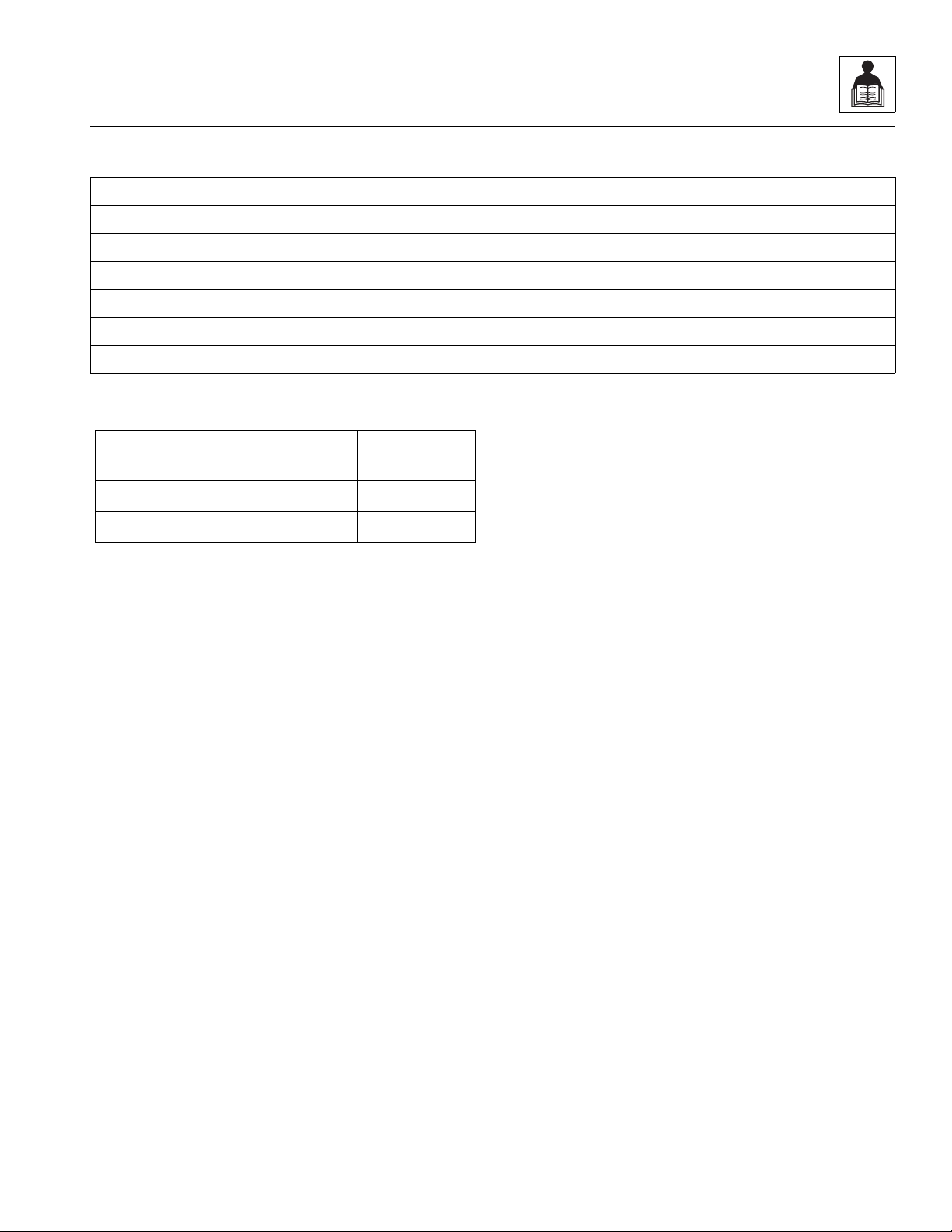
METRIC CLASS 8.8 METRIC CLASS 10.9
2.2.3 Metric Fastener Torque Chart
VALUES FOR ZINC PLATED / YELLOW CHROMATE FASTENERS ONLY
CLASS 8.8 METRIC BOLTS &
CLASS 8 METRIC NUTS
TORQUE
LUB
LOCTITE
262
LOCTITE
242 OR
271
CLAMP
SIZE PITCH
TENSILE
STRESS
AREA
CLAMP
LOAD
DRY OR
LOCTITE
263
sq. mm KN N, m N, m N, m N, m KN N, m N, m N, m N, m
3 .5 5.03 2.19 1.3 1.0 1.2 1.4 3.13 1.9 1.4 1.5 2.1
3.5 .6 6.78 2.95 2.1 1.6 1.9 2.3 4.22 3.0 2.2 2.4 3.3
4 .7 8.78 3.82 3.1 2.3 2.8 3.4 5.47 4.4 3.3 3.5 4.8
5 .8 14.2 6.18 6.2 4.6 5.6 6.8 8.85 8.9 6.6 7.1 9.7
6 1 20.1 8.74 11 7.9 9.4 12 12.5 15 11 12 17
7 1 28.9 12.6 18 13 16 19 18 25 19 20 28
81.2536.615.92519232822.837272940
10 1.5 58.0 25.2 50 38 45 55 36.1 72 54 58 79
12 1.75 84.3 36.7 88 66 79 97 52.5 126 95 101 139
14 2 115 50.0 140 105 126 154 71.6 200 150 160 220
16 2 157 68.3 219 164 197 241 97.8 313 235 250 344
18 2.5 192 83.5 301 226 271 331 119.5 430 323 344 473
20 2.5 245 106.5 426 320 383 469 152.5 610 458 488 671
22 2.5 303 132.0 581 436 523 639 189.0 832 624 665 915
24 3 353 153.5 737 553 663 811 220.0 1060 792 845 1170
27 3 459 199.5 1080 810 970 1130 286.0 1540 1160 1240 1690
30 3.5 561 244.0 1460 1100 1320 1530 349.5 2100 1570 1680 2310
33 3.5 694 302.0 1990 1490 1790 2090 432.5 2600 2140 2280 2860
36 4 817 355.0 2560 1920 2300 2690 509.0 3660 2750 2930 4020
42 4.5 1120 487.0 4090 3070 3680 4290 698.0 5860 4400 4690 6440
CLASS 10.9 METRIC BOLTS &
CLASS 10 METRIC NUTS
LOAD
DRY OR
LOCT ITE
263
LUB
TORQUE
LOCTITE
262
LOCTITE
242 OR
271
Note: These torque values do not apply to cadmium plated fasteners.
4017
2.5

General Information and Specifications
2.3 SPECIFICATIONS
2.3.1 Travel Speeds
Description
First Gear 5,2 km/h (3.2 mph)
Second Gear 11 km/h (6.9 mph)
Third Gear 22,5 km/h (14 mph)
Fourth Gear 35 km/h (21.7 mph)
2.3.2 Engine Performance Specifications
Note: Engine manufacturer's maximum “high idle” setting is lockwired and sealed. DO NOT disturb this setting.
Description
Engine Make/Model Perkins 1004-40T
Low Idle 925 ±50 rpm
High Idle 2200 ±50 rpm
Horsepower 99.5 BHP / 74.5 kW @ 2200 rpm
Fuel Delivery Fuel Injection
Air Cleaner Dry Type, Replaceable Pr im ar y and Safety
Elements
2.3.3 Hydraulic Cylinder Performance
Function Approximate Times (seconds)
Extend Cylinder Extend 23.0
Extend Cylinder Retract 18.0
Lift Retracted 15.5
Lower Retracted 10.0
Attachment Tilt - UP 4.5
Attachment Tilt - DOWN 9.8
Outrigger - Left and Right, DOWN 8.7
Outrigger - Left and Right, UP 6.4
2.6
4017
General Information and Specifications
2.3.4 Tires
Description
Wheel Lug Nut Torque 550-600 Nm (405-445 lb-ft)
Standard Tire Size 405/70-24 14PR MPT-04 TBL
Standard Tire Air Pressure (Minimum) 450 kPa (65 psi)
Optional Tires
Opti on al Tir e Size 405/70-24 14PR MPT-01 TBL
Opti o nal Tire Air P ressu re (Mi n i mum) 450 kPa (65 psi)
2.3.5 Axles
Dana Spicer
Model
212-531 FRONT 1:20.667 0280173
212-190-002 REAR 1:20.667 4803383
Axle JLG P/N
4017
2.7

General Information and Specifications
2.3.6 Electrical System
Battery:
Type, Rating 12 VDC, Negative (-) Ground, Maintenance Free
Quantity 1
Reserve Capacity 1,000 Cold Cranking Amps @ 0° F (-18° C)
Group/Series Series 31
Alternator 12V, 85 Amps
Fuses - Standard Blade Style:
5 Amps Radio
7.5 Amps Headlights and Tail Lights, ESX Ignition and Sensors
10 Amps Brake Lights, Cold Start, Beacon
15 Amps Rear Work Lights, Cab Heater, Aux Power Socket,
Battery Ind. Light, Dome Light, Spare, Ignition, Front
Work Lights, Boom Work Lights,
20 Amps Rear Wiper, Front Wiper
25 Amps ESX Battery, Air Conditioning
30 Amps Key Switch
Relays:
Key (power) K1
Start Interlock K2
Flasher K3
Wiper K4
Work Lights K5
Fuel Solenoid K6
Relays in Engine Compartment:
Starter
Lift pump
Glow Plug
Inline Fuse:
Lift Pump and Glow Plug
2.8
4017

General Information and Specifications
2.4 FLUIDS, LUBRICANTS AND CAPACITIES
Engine Crankcase Oil
Capacity w/Filter Change 8,5 liters (9 quarts)
Filter Capacity 1,0 liter (0.26 quarts)
Type of Oil 15W-40 CE/SE
Fuel Filters
Primary Fuel Filter Capacity Approx. 1,0 liter (0.26 quarts)
Fuel Filter Capacity 0,6 liters (0.16 quarts)
Fuel Tank
Capacity 140 liters (37 gallons)
Type of Fuel U.S.A. #2 Diesel
Cooling System
System Capacity w/o Heater 19,7 liters (20.8 quarts)
Type of Fluid 50/50 mix of ethylene glycol & water
Transmission Fluid
Capacity w/filter change 12,9 liter (13.6 quarts)
Filter Capacity 1,4 liters (1.5 quarts)
Type of Fluid Mobilfluid 424
®
Tractor Hydraulic Fluid (ISO 46)
Transmission Transfer Case (Drop Box)
Capacity 1,4 liter (1.5 quarts)
Type of Fluid Mobilfluid 424
®
Tractor Hydraulic Fluid (ISO 46)
Axles
Differential Housing Capacity - Front 6,9 liters (1.3 quarts)
Differential Housing Capacity - Rear 6,9 liters (1.3 quarts)
Wheel End Capacity 1,25 liters (1.3 quarts)
Type of Fluid Mobilfluid 424
®
Tractor Hydraulic Fluid (ISO 46)
Brakes
Master Cylinder Capacity 0,7 liters (0.7 quarts)
Type of Fluid ATF Dexron II
Hydraulic System
System Capacity 246 liters (65 gallons)
Reservoir Capacity to FULL Mark 160 liters (42.3 gallons)
Type of Fluid Mobilfluid 424
4017
®
Tractor Hydraulic Fluid (ISO 46)
2.9
General Information and Specifications
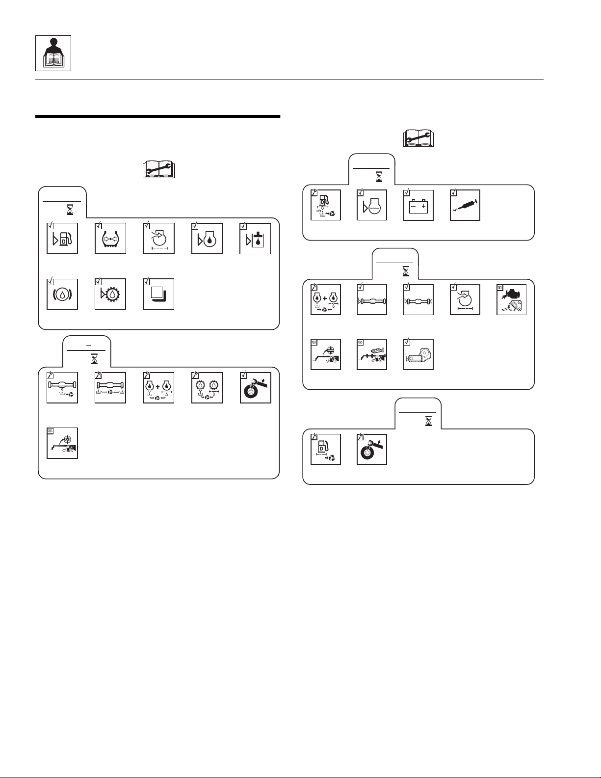
OZ0300
Check Wheel
Lug Nut
Torque
LB/FT (Nm)
Change
Axle Oil
Change Wheel
End Oil
50
1
st
Check Boom
Chain Tension
Change Engine
Oil & Filter
Change
Transmission
Oil & Filter
Air Filter
Restriction
Indicator
Check Fuel
Level
Check Engine
Oil Level
Check Tire
Pressure
8
EVERY
Check Brake
Fluid Level
Check
Transmission
Oil Level
Test Load
Moment
Indicator
Check Hydraulic
Oil Level
OZ0320
500
EVERY
Check Wheel
Lug Nut
Torque
LB/FT (Nm)
Change Fuel
Filter
50
EVERY
Drain Fuel/
Water
Separator
Check Engine
Coolant Level
Check
Battery
Follow Lubrication
Schedule
250
EVERY
Check Axle
Oil Level
Check Wheel
End Oil Levels
Air Filter
Vacuator
Valve
Check
Fan Belt
Check Boom
Chain
Tension
Check Boom
Bearing
Pads
Check Transfer
Case Oil Level
Change Engine
Oil and
Filter
2.5 SERVICE AND MAINTENANCE SCHEDULES
2.5.1 8 & 1st 50 Hour Maintenance Schedule
2.5.2 50, 250 & 500 Hour Maintenance Schedule
2.10
4017
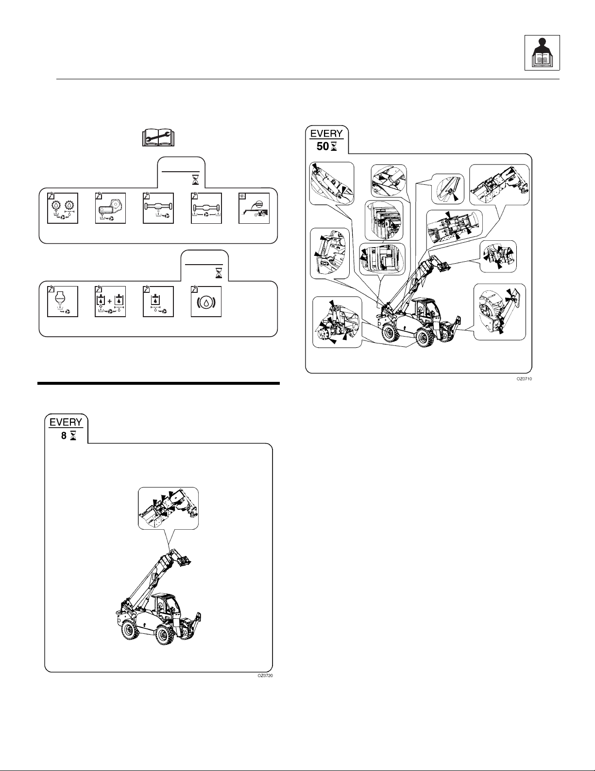
General Information and Specifications
OZO891
1500
EVERY
Change
Engine Coolant
Change
Hydraulic
Fluid & Filters
Change
Hydraulic Tank
Breather
Change
Brake Fluid
1000
EVERY
Change
Axle Oil
Change Wheel
End Oil
Change
Transmission
Oil & Filter
Change
Transfer Case
Oil
Check Boom
Chain
(4017 only)
Mystik T e trimo ly
(NLGI 2 GC-LB)
Mystik Tetrimoly
(NLGI 2 GC-LB)
2.5.3 1000 & 1500 Hour Maintenance Schedule
2.6 LUBRICATION SCHEDULES
2.6.2 50 Hour Lube Schedule
2.6.1 8 Hour Lube Schedule
4017
2.11

General Information and Specifications
This Page Intentionally Left Blank
2.12
4017

Section 3
Boom
Contents
PARAGRAPH TITLE PAGE
3.1 Boom System Component Terminology. . . . . . . . . . . . . . . . . . . . . . . . . . . . . . . . 3.2
3.2 Boom System . . . . . . . . . . . . . . . . . . . . . . . . . . . . . . . . . . . . . . . . . . . . . . . . . . . . . 3.3
3.2.1 Boom System Operation. . . . . . . . . . . . . . . . . . . . . . . . . . . . . . . . . . . . . . 3.3
3.3 Boom Assembly Maintenance. . . . . . . . . . . . . . . . . . . . . . . . . . . . . . . . . . . . . . . . 3.3
3.3.1 Boom Removal . . . . . . . . . . . . . . . . . . . . . . . . . . . . . . . . . . . . . . . . . . . . . 3.3
3.3.2 Second, Third & Fourth Boom Section Removal . . . . . . . . . . . . . . . . . . . 3.4
3.3.3 Third & Fourth Boom Section Removal. . . . . . . . . . . . . . . . . . . . . . . . . . . 3.6
3.3.4 Fourth Boom Section Removal. . . . . . . . . . . . . . . . . . . . . . . . . . . . . . . . . 3.6
3.3.5 Hose Carrier Removal. . . . . . . . . . . . . . . . . . . . . . . . . . . . . . . . . . . . . . . . 3.7
3.3.6 Hose Carrier Installation . . . . . . . . . . . . . . . . . . . . . . . . . . . . . . . . . . . . . . 3.7
3.3.7 Fourth Boom Section Installation . . . . . . . . . . . . . . . . . . . . . . . . . . . . . . . 3.8
3.3.8 Third & Fourth Boom Section Installation . . . . . . . . . . . . . . . . . . . . . . . . . 3.9
3.3.9 Second, Third & Fourth Boom Section Installation . . . . . . . . . . . . . . . . . . 3.10
3.3.10 Boom Installation. . . . . . . . . . . . . . . . . . . . . . . . . . . . . . . . . . . . . . . . . . . . 3.13
3.4 Boom Extend and Retract Chains . . . . . . . . . . . . . . . . . . . . . . . . . . . . . . . . . . . . . 3.14
3.4.1 Boom Chain Inspection. . . . . . . . . . . . . . . . . . . . . . . . . . . . . . . . . . . . . . . 3.14
3.5 Boom Section Separation Adjustment . . . . . . . . . . . . . . . . . . . . . . . . . . . . . . . . . 3.17
3.6 Hose Carrier Assembly. . . . . . . . . . . . . . . . . . . . . . . . . . . . . . . . . . . . . . . . . . . . . . 3.18
3.6.1 Hose Carrier Assembly Removal . . . . . . . . . . . . . . . . . . . . . . . . . . . . . . . 3.18
3.6.2 Hose Carrier Assembly Replacement. . . . . . . . . . . . . . . . . . . . . . . . . . . . 3.19
3.7 Boom Wear Pads. . . . . . . . . . . . . . . . . . . . . . . . . . . . . . . . . . . . . . . . . . . . . . . . . . . 3.21
3.7.1 Wear Pad Inspection. . . . . . . . . . . . . . . . . . . . . . . . . . . . . . . . . . . . . . . . . 3.21
3.7.2 Boom Wear Pad Replacement . . . . . . . . . . . . . . . . . . . . . . . . . . . . . . . . . 3.21
3.7.3 Boom Wear Pad Lubrication . . . . . . . . . . . . . . . . . . . . . . . . . . . . . . . . . . . 3.23
3.8 Quick Switch Assembly . . . . . . . . . . . . . . . . . . . . . . . . . . . . . . . . . . . . . . . . . . . . . 3.23
3.8.1 Connecting with a Mechanical Quick Switch Device. . . . . . . . . . . . . . . . . 3.23
3.8.2 Connecting with a Hydraulic Quick Switch Device . . . . . . . . . . . . . . . . . . 3.23
3.8.3 Connecting with a Quick Switch to a Hydraulic Operated Attachment . . . 3.24
3.8.4 Quick Switch Removal . . . . . . . . . . . . . . . . . . . . . . . . . . . . . . . . . . . . . . . 3.24
3.8.5 Quick Switch Installation. . . . . . . . . . . . . . . . . . . . . . . . . . . . . . . . . . . . . . 3.24
3.9 Troubleshooting . . . . . . . . . . . . . . . . . . . . . . . . . . . . . . . . . . . . . . . . . . . . . . . . . . . 3.25
4017
3.1
Boom
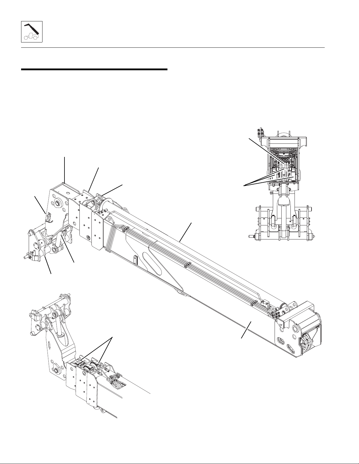
MZ0800
MZ0810
MZ0830
Extend/Retract
Cylinder
First Boom
Section
Auxiliary
Quick
Connects
Tilt Cylinder
Second Boom
Section
Third Boom
Section
Fourth Boom
Section
Hose Carrier
Extend Chains
(two pair)
Bottom View
Quick Switch Assembly
Rear View
Retract Chains
(three)
3.1 BOOM SYSTEM COMPONENT TERMINOLOGY
To understand the safety, operation and maintenance
information presented in this section, it is necessary that
the operator/mechanic be familiar with the name and
location of the major assemblies of the boom system. The
following illustration identifies the components that are
referred to throughout this section.
3.2
4017
Boom
MZ0420
EXT/RET
LIFT
TILT
AUX
SWAY
L. O/R
R. O/R
FRONT OF
MACHINE
1
3.2 BOOM SYSTEM
3.2.1 Boom System Operation
The four section boom consists of the first, second, third
and fourth assemblies with double third and fourth
section extend chains, a double third section retract
chains and a single fourth section retract chain.
As the extend/retract cylinder, which is anchored at the
front of the second boom section, and the rear of the first
boom section begins to extend, it forces the second boom
section out of the first boom section.
The first, second, third and fourth boom sections are
connected by extend and retract chains. These chains
are routed around sheaves on the second and third boom
sections. As the second and third boom sections are
forced out, the extend chain pulls the fourth boom section
out of the third boom section.
As hydraulic pressure is applied to the retract port on the
extend/retract cylinder, the second boom section is pulled
back into the first boom section, and the retract chain
pulls the third and fourth boom sections back into the
second boom section.
This mechanical linkage formed by the chains and
supporting hardware, extends and retracts the third and
fourth boom sections at the same rate.
The first boom section does not extend or retract, but lifts
and lowers via action of the lift cylinder.
3.3.1 Boom Removal
1. Remove any attachment from the quick switch
assembly. (Refer to Section 3.8.1, “Connecting with
a Mechanical Quick Switch Device.”)
2. Set the quick attach assembly in a vertical position
and set on a hard level surface. Refer to Section
3.8.4, “Quick Switch Removal,” for disassembly
instructions.
3. Park the machine on a firm, level surface. Be sure
there is enough room in front of the machine to allow
the boom sections to be removed. Fully retract the
boom then raise the boom to access the rod end pin
of lift cylinder. Place the transmission control lever in
(N) NEUTRAL, engage the park brake and shut the
engine OFF.
4. Open the engine cover. Allow the system fluids to
cool.
5. Place an Accident Prevention Tag on both the
ignition key switch and the steering wheel, stating
that the machine should not be operated.
3.3 BOOM ASSEMBLY MAINTENANCE
The boom assembly consists of the first, second, third
and fourth boom sections and supporting hardware.
IMPORTANT: Before removing the boom, the carriage
or any other attachment must be removed from the quick
switch assembly.
These instructions must be completed in sequence. The
second, third and fourth boom sections are removed from
the first boom section.The third and fourth boom sections
are removed from the second boom section.The fourth
boom section is removed from the third boom section.
Before beginning, conduct a visual inspection of the
machine and work area, and review the task about to be
undertaken. Read, understa nd and follow thes e
instructions.
4017
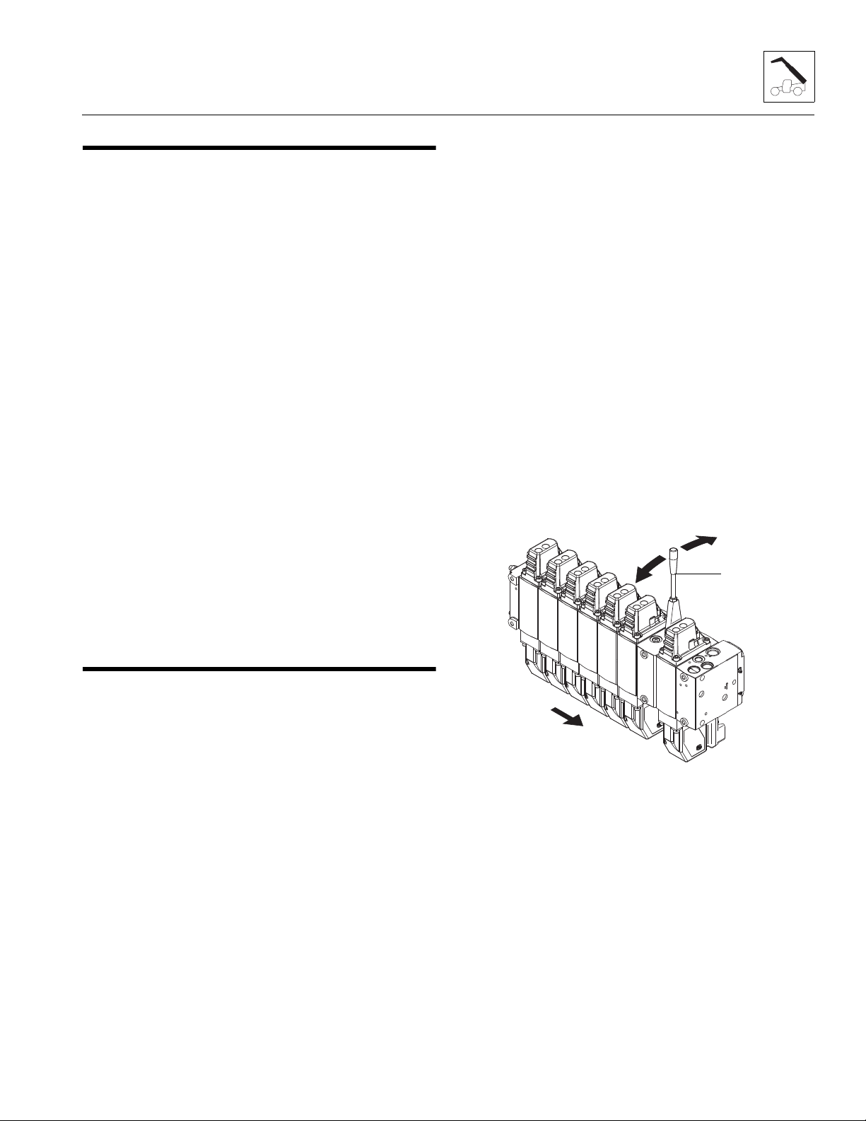
6. Relieve any trapped pressure in the tilt hydraulic
system by installing the handle (1) (located in the
toolbox) or using an 9mm wrench and move the
double nut on the side of the actuator module on the
tilt valve section back and forth. Repeat on the
auxiliary valve section and on the extend/retract
valve section.
7. Disconnect, label and cap both hoses from the
extend/retract cylinder, tilt hoses and both auxiliary
hoses from tubes at left rear corner of first boom
section to prevent dirt and debris from entering
hydraulic system.
8. Remove the extend/retract cylinder support at the
top front of the first boom section.
3.3
Boom
MZ0820
1
(before being turned over)
MZ0740
2
(after being turned over)
MZ0750
3
9. Support the extend/retract cylinder and remove the
clip and pin from rod end of extend/retract cylinder.
Remove the clip and pin from barrel end of extend/
retract cylinder and remove the extend/retract
cylinder.
10. Disconnect the boom angle indicator rod from switch
at the inside left rear corner of the main boom
section and frame. Refer to Section 9.11.9, “Boom
Angle Sensor,” for adjustment information.
11. Support the front of the boom by placing a sling
behind the boom head. Support the lift/lower cylinder
and remove the lock bolt and then the rod end pin.
Lower the lift/lower cylinder onto the frame rails.
12. Remove the lock bolt and pin from compensation
cylinder on each side of first boom section. Remove
the lock bolt and pivot pin from rear of first boom
section.
13. Lower the boom to a level position and place a
suitable support under the boom head. Reposition
the slings to each end of the boom.
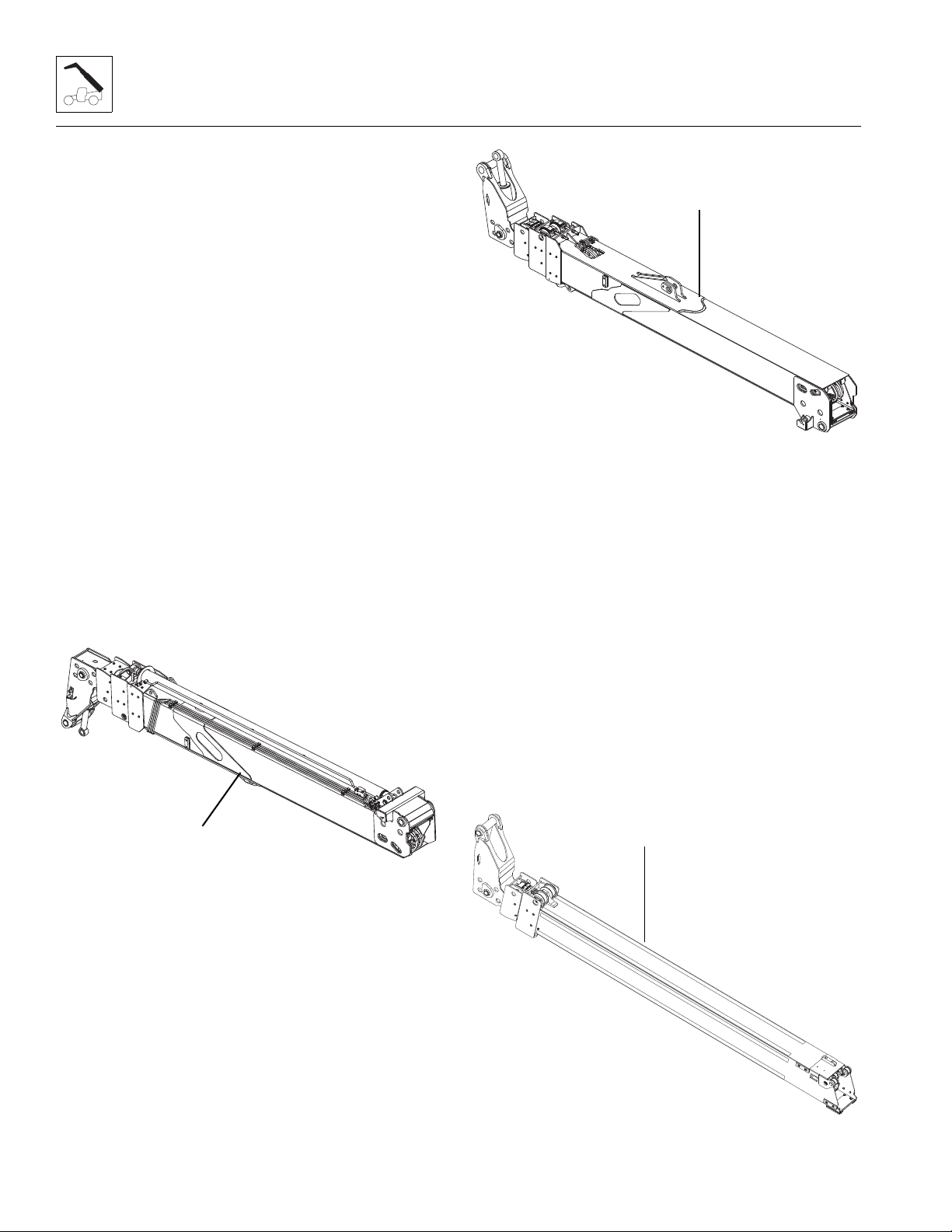
14. Lift the complete boom (1) off machine and set on
level ground or supports being careful not to damage
the tubes on the left side of boom.
3.3.2 Second, Third & Fourth Boom Sectio n Removal
1. Set the complete boom on level ground and by
repositioning the slings turn boom over on to the top
side. Set the complete boom (2) on suitable stands
to begin tear down.
Note: With the complete boom setting upside down, the
removal and replacing of each boom section, tilt cylinder,
hoses, extend and retract chains and hose carrier are
made much easier.
Note: In the following sections the individual boom
sections are removed as follows:
1. Remove second, third and fourth boom sections as
one unit from the first boom section.
2. Remove third and fourth boom sections as one unit
from the second boom section.
3. Remove fourth boom section from the third boom
section.
4. Remove hose carrier from fourth boom section.
2. At the boom head attach a sling through rod end of
tilt cylinder. Remove both hoses from tilt cylinder.
Plug the hose ends and cap the tilt cylinder fittings to
prevent dirt and debris from entering the hydraulic
system. Remove the clip from barrel end of tilt
cylinder pin. Remove the tilt cylinder pin and lift the
tilt cylinder out of the boomhead.
3.4
4017
Boom
MZ0790
1
1
3. Use a suitable sling around the third section boom to
take any pressure off of wear pads to make pad
removal easier.
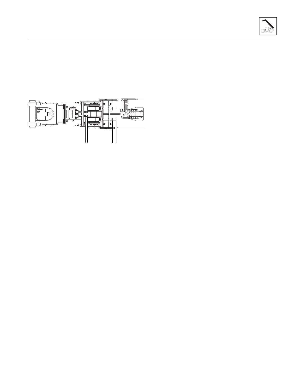
Note: Before removing the extend chains, measure the
distance (1) between the face of the jam nut to the end of
the chain clevis on all four extend chains. This
measurement will be used when reassembling the
boom.
4. At the bottom front of the first section boom remove
the jam nuts and nuts and washers from the two
extend chain clevises. Remove clips and pins from
the two clevises and remove clevis from each chain.
5. At the bottom front of the second section boom
remove the jam nuts and nuts and washers from the
two extend chain clevises. Remove clips and pins
from the two clevises and remove clevis from each
chain.
6. At the rear of boom, loosen and unscrew both tilt
hoses and both auxiliary hoses from bulkhead on
hose carrier. Plug the hose ends and cap the
bulkhead fittings to prevent dirt and debris from
entering the hydraulic system.
7. Remove the clip and pin from both retract chain
clevises that are attached to the rear of the third
section boom. The pins can be removed through the
access holes at t h e b ot to m le f t an d right sides of t h e
first section boom. Do not remove the clev ises
8. Remove the clip and pin from the retract chain clevis
that is attached to the rear of the fourth boom
section. Do not remove the clevis.
9. Pull the second section boom out
152 mm to 203 mm (6 in to 8 in) to be able to loosen
and remove all the bolts and remove all the wear
pads, backing plates and shims from the front inside
of the first section boom. Tag each pad, backing
plate, shim and bolts from each location.
10. Pull the third boom section out 152 mm to 203 mm
(6 in to 8 in) to be able to access the wear pad bolts
on the rear of the second section boom. Remove the
top left and right side wear pads, backing plates and
shims (one on each side) from the second boom
section. Loosen the bottom rear wear pad bolts and
remove the shims from the second boom section to
gain the necessary clearance to be able to remove
the second boom section from the first boom
section. Tag each pad, backing plate, shim and bolts
from each location.
11. Using a sling around the front of the second boom
section, lift and slide the three boom sections 3/4 of
the way out of the first boom section. Set the boom
head down on a suitable support, then center the
sling to be able to balance the three boom sections
being removed. Carefully pull the three boom
sections (3) the remainder of the way out of the first
boom section and set the three boom sections down
on suitable supports.
12. Remove the clip and pin holding each retract chain
from the inside of the first boom section. Clean and
inspect chains. Replace if damaged.
13. Unscrew the tilt and auxiliary hoses from tubes at
bottom front of first boom section. Plug the tilt and
auxiliary hoses and cap the tubes to prevent dirt and
debris from entering hydraulic system. Clean and
inspect the hoses. Replace if damaged.
14. Inspect the boom and welds. Consult the local JLG
distributor or the JLG Service Department i f stru ctural
damage is detected.
15. Inspect hoses, hardware, wear pads, mounting
points, chains and other components visible with the
first boom section. Replace any item if damaged.
(Refer to Section 3.4.1, 3.4.1. “Boom Chain
Inspection,” and Section 3.7.1, 3.7.1. “Wear Pad
Inspection.”)
Note: It is recommended that if any chain or hose is
damaged that ALL chains or hoses are replaced.
4017
3.5

Boom
MZ0760
1
3.3.3 Third & Fourth Boom Section Removal
1. With the three boom sections setting on suitable
supports remove bolts, keeper and pin from both
sheaves on the bottom front of the second boom
section. Remove sheaves. Remove all the wear
pads, backing plates and shims from the front inside
of the second boom section. Tag each pad, backing
plate, shim and bolts from each location.
2. Remove the bolts, keeper and pin from center
sheave on the bottom rear of the third boom section.
Remove the sheave.
3. Remove the top left and right side rear wear pads,
backing plates and shims (one on each side) from
the third boom section. Loosen the bottom rear wear
pad bolts and remove the shims from the third boom
section to gain the necessary clearance to remove
the third boom section from the second boom
section. Tag each pad, backing plate, shim and bolts
from each location.
4. Place a sling around the front of the third boom
section. Lift and slid the two boom sections 3/4 of the
way out of the second boom section.Set the boom
head down on a suitable support, then center the
sling to be able to balance the two boom sections
being removed. Carefully pull the two boom sections
(1) the remainder of the way out of the second boom
section and set the two boom sections down on
suitable supports.
5. Remove the lock bolts, keeper and pin from both
sheaves at bottom rear of the second section boom.
Remove the sheave’s.
6. Remove the clip and pin holding retract chain from
bottom front of second boom section. Clean and
inspect chain. Replace if damaged.
7. Inspect the boom and welds. Consult the local JLG
distributor or the JLG Service Department if structural
damage is detected.
8. Inspect hoses, hardware, wear pads, mounting
points, chains and other components visible with the
first boom section. Replace any item if damaged.
(Refer to Section 3.4.1, 3.4.1. “Boom Chain
Inspection,” and Section 3.7.1, 3.7.1. “Wear Pad
Inspection.”)
Note: It is recommended that if any chain or hose is
damaged that ALL chains or hoses are replaced.
3.3.4 Fourth Boom Section Removal
1. With the two boom sections setting on suitable
supports remove the bolts, keeper and pin from
sheave on the front of the third boom section.
Remove the sheaves. Remove all the wear pads,
backing plates and shims from the front inside of the
third boom section. Tag each pad, backing plate,
shim and bolts from each location.
2. Remove the top left and right side rear wear pads,
backing plates and shims (one on each side) from
the fourth boom section. Loosen the bottom rear
wear pad bolts and remove the shims from the fourth
boom section to gain the necessary clearance to be
able to remove the fourth boom section from the
third boom section.Tag each pad, backing plate,
shim and bolts from each location.
3. Loosen and remove the two bolts holding the rear of
the catrack to the top of the third boom section. Lift
and push rear of hose carrier into the fourth boom
section.
4. Place a sling around the front of the fourth boom
section (2). Lift and slid the fourth boom section 3/4
of the way out of the third boom section. Set the
boom head down on a suitable support, then center
the sling to be able to balance the fourth boom
section being removed. Carefully pull the fourth
boom section the remainder of the way out of the
third boom section and set the fourth boom section
down on suitable supports.
5. Remove the clip and pin holding both extend chains
from bottom of third and fourth boom sections. Clean
and inspect chains. Replace if damaged.
3.6
4017
 Loading...