


Operation and Safety Manual
Original Instructions - Keep this manual with the machine at all times.
Boom Lift Models 600SC
660SJC
S/N 74785 to Present
ANSI |
|
|
|
|
|
|
|
|
|
|
3121156 |
|
|
|
|
|
|
|
|
|
|
||
|
|
|
|
|
|
|
|
|
|
May 4, 2012 |
|
|
|
|
|
|
|
® |
|
||||

FOREWORD
FOREWORD
This manual is a very important tool! Keep it with the machine at all times.
The purpose of this manual is to provide owners, users, operators, lessors, and lessees with the precautions and operating procedures essential for the safe and proper machine operation for its intended purpose.
Due to continuous product improvements, JLG Industries, Inc. reserves the right to make specification changes without prior notification. Contact JLG Industries, Inc. for updated information.
3121156 |
– JLG Lift – |
a |

FOREWORD
SAFETY ALERT SYMBOLS AND SAFETY SIGNAL WORDS
This is the Safety Alert Symbol. It is used to alert you to the potential personal injury hazards. Obey all safety messages that follow this symbol to avoid possible injury or death
INDICATES AN IMMINENTLY HAZARDOUS SITUATION. IF NOT AVOIDED, WILL RESULT IN SERIOUS INJURY OR DEATH. THIS DECAL WILL HAVE A RED BACKGROUND.
INDICATES A POTENTIALLY HAZARDOUS SITUATION. IF NOT AVOIDED, COULD RESULT IN SERIOUS INJURY OR DEATH. THIS DECAL WILL HAVE AN ORANGE BACKGROUND.
INDICATES A POTENTIALLY HAZARDOUS SITUATION. IF NOT AVOIDED, MAY RESULT IN MINOR OR MODERATE INJURY. IT MAY ALSO ALERT AGAINST UNSAFE PRACTICES. THIS DECAL WILL HAVE A YELLOW BACKGROUND.
INDICATES INFORMATION OR A COMPANY POLICY THAT RELATES DIRECTLY OR INDIRECTLY TO THE SAFETY OF PERSONNEL OR PROTECTION OF PROPERTY.
b |
– JLG Lift – |
3121156 |

FOREWORD
THIS PRODUCT MUST COMPLY WITH ALL SAFETY RELATED BULLETINS. CONTACT JLG INDUSTRIES, INC. OR THE LOCAL AUTHORIZED JLG REPRESENTATIVE FOR INFORMATION REGARDING SAFETYRELATED BULLETINS WHICH MAY HAVE BEEN ISSUED FOR THIS PRODUCT.
JLG INDUSTRIES, INC. SENDS SAFETY RELATED BULLETINS TO THE OWNER OF RECORD OF THIS MACHINE. CONTACT JLG INDUSTRIES, INC. TO ENSURE THAT THE CURRENT OWNER RECORDS ARE UPDATED AND ACCURATE.
JLG INDUSTRIES, INC. MUST BE NOTIFIED IMMEDIATELY IN ALL INSTANCES WHERE JLG PRODUCTS HAVE BEEN INVOLVED IN AN ACCIDENT INVOLVING BODILY INJURY OR DEATH OF PERSONNEL OR WHEN SUBSTANTIAL DAMAGE HAS OCCURRED TO PERSONAL PROPERTY OR THE JLG PRODUCT.
For:
• Accident Reporting |
• Standards and Regulations |
|
• Product Safety Publica- |
Compliance Information |
|
|
||
tions |
• Questions Regarding Spe- |
|
• Current Owner Updates |
cial Product Applications |
|
|
||
• Questions Regarding |
• Questions Regarding Prod- |
|
uct Modifications |
||
Product Safety |
||
|
Contact:
Product Safety and Reliability Department
JLG Industries, Inc.
13224 Fountainhead Plaza
Hagerstown, MD 21742
USA
or Your Local JLG Office
(See addresses on inside of manual cover)
In USA:
Toll Free: 877-JLG-SAFE (877-554-7233)
Outside USA:
Phone: 240-420-2661
Fax: 301-745-3713
E-mail: ProductSafety@JLG.com
3121156 |
– JLG Lift – |
c |

FOREWORD
|
REVISION LOG |
Original Issue |
- October 28, 2003 |
Revised |
- May 4, 2005 |
Revised |
- July 18, 2006 |
Revised |
- September 13, 2006 |
Revised |
- July 30, 2009 |
Revised |
- August 19, 2009 |
Revised |
- December 1, 2009 |
Revised |
- April 3, 2012 |
Revised |
- May 4, 2012 |
d |
– JLG Lift – |
3121156 |

TABLE OF CONTENTS
SECTION - PARAGRAPH, SUBJECT |
PAGE |
SECTION - 1 - SAFETY PRECAUTIONS
1.1 GENERAL . . . . . . . . . . . . . . . . . . . . . . . . . . . . . . . . .1-1
1.2 PRE-OPERATION . . . . . . . . . . . . . . . . . . . . . . . . . . .1-1
Operator Training and Knowledge . . . . . . . . . . . 1-1
Workplace Inspection. . . . . . . . . . . . . . . . . . . . . 1-2
Machine Inspection . . . . . . . . . . . . . . . . . . . . . . 1-2
1.3 OPERATION . . . . . . . . . . . . . . . . . . . . . . . . . . . . . . .1-3
General . . . . . . . . . . . . . . . . . . . . . . . . . . . . . . . . 1-3
Trip and Fall Hazards . . . . . . . . . . . . . . . . . . . . . 1-3
Electrocution Hazards . . . . . . . . . . . . . . . . . . . . 1-4
Tipping Hazards . . . . . . . . . . . . . . . . . . . . . . . . . 1-6
Crushing and Collision Hazards. . . . . . . . . . . . . 1-7
1.4 TOWING, LIFTING, AND HAULING . . . . . . . . . . . . .1-8
1.5 ADDITIONAL HAZARDS / SAFETY . . . . . . . . . . . . .1-9
SECTION - 2 - USER RESPONSIBILITIES, MACHINE PREPA-
RATION, AND INSPECTION
2.1 PERSONNEL TRAINING . . . . . . . . . . . . . . . . . . . . .2-1
Operator Training . . . . . . . . . . . . . . . . . . . . . . . . 2-1
Training Supervision. . . . . . . . . . . . . . . . . . . . . . 2-1
Operator Responsibility . . . . . . . . . . . . . . . . . . . 2-1
2.2PREPARATION, INSPECTION, AND
MAINTENANCE . . . . . . . . . . . . . . . . . . . . . . . . . . .2-2
Pre-Start Inspection . . . . . . . . . . . . . . . . . . . . . . 2-4
Daily Functional Check. . . . . . . . . . . . . . . . . . . . 2-5
SECTION - PARAGRAPH, SUBJECT |
PAGE |
General . . . . . . . . . . . . . . . . . . . . . . . . . . . . . . . 2-12
SECTION - 3 - MACHINE CONTROLS AND INDICATORS
3.1 GENERAL . . . . . . . . . . . . . . . . . . . . . . . . . . . . . . . . 3-1
3.2 CONTROLS AND INDICATORS . . . . . . . . . . . . . . . 3-1
Ground Control Station . . . . . . . . . . . . . . . . . . . . 3-1
Ground Control Indictor Panel . . . . . . . . . . . . . . 3-6
Platform Control Station . . . . . . . . . . . . . . . . . . . 3-9
Platform Control Indicator Panel . . . . . . . . . . . . 3-16
SECTION - 4 - MACHINE OPERATION
4.1 DESCRIPTION. . . . . . . . . . . . . . . . . . . . . . . . . . . . . 4-1 4.2 ENGINE OPERATION . . . . . . . . . . . . . . . . . . . . . . . 4-2 Starting Procedure . . . . . . . . . . . . . . . . . . . . . . . 4-2 Shutdown Procedure . . . . . . . . . . . . . . . . . . . . . 4-3 4.3 TRAVELING (DRIVING) . . . . . . . . . . . . . . . . . . . . . . 4-3 Traveling Forward or Reverse . . . . . . . . . . . . . . . 4-6 Stability . . . . . . . . . . . . . . . . . . . . . . . . . . . . . . . . 4-8
4.4 STEERING. . . . . . . . . . . . . . . . . . . . . . . . . . . . . . . 4-10 4.5 PARKING AND STOWING . . . . . . . . . . . . . . . . . . 4-10 4.6 PLATFORM . . . . . . . . . . . . . . . . . . . . . . . . . . . . . . 4-10 Platform Level Adjustment . . . . . . . . . . . . . . . . 4-10 Platform Rotation. . . . . . . . . . . . . . . . . . . . . . . . 4-10 4.7 BOOM . . . . . . . . . . . . . . . . . . . . . . . . . . . . . . . . . . 4-11 Swinging the Boom . . . . . . . . . . . . . . . . . . . . . . 4-11
3121156 |
– JLG Lift – |
i |

TABLE OF CONTENTS
SECTION - PARAGRAPH, SUBJECT |
PAGE |
Raising and Lowering the Main Boom . . . . . . 4-11 Telescoping the Main Boom . . . . . . . . . . . . . . 4-12 4.8 SHUT DOWN AND PARK . . . . . . . . . . . . . . . . . . . 4-12
4.9 TIE DOWN AND LIFTING. . . . . . . . . . . . . . . . . . . . 4-12 Tie Down . . . . . . . . . . . . . . . . . . . . . . . . . . . . . 4-12 Lifting . . . . . . . . . . . . . . . . . . . . . . . . . . . . . . . . 4-12
4.10 AUXILIARY POWER . . . . . . . . . . . . . . . . . . . . . . . . 4-13 4.11 HYDRAULIC TOOL CIRCUIT INSTRUCTIONS
(OPTIONAL). . . . . . . . . . . . . . . . . . . . . . . . . . . . . 4-16 Tool Circuit . . . . . . . . . . . . . . . . . . . . . . . . . . . . 4-16 4.12 PLACARDS AND DECALS. . . . . . . . . . . . . . . . . . . 4-18
SECTION - 5 - EMERGENCY PROCEDURES
5.1 GENERAL . . . . . . . . . . . . . . . . . . . . . . . . . . . . . . . . 5-1 5.2 INCIDENT NOTIFICATION. . . . . . . . . . . . . . . . . . . . 5-1 5.3 EMERGENCY OPERATION. . . . . . . . . . . . . . . . . . . 5-2 Operator Unable to Control Machine . . . . . . . . 5-2 Platform or Boom Caught Overhead. . . . . . . . . 5-2
SECTION - 6 - GENERAL SPECIFICATIONS & OPERATOR MAINTENANCE
6.1 INTRODUCTION . . . . . . . . . . . . . . . . . . . . . . . . . . . 6-1 6.2 OPERATING SPECIFICATIONS . . . . . . . . . . . . . . . 6-1 Capacities . . . . . . . . . . . . . . . . . . . . . . . . . . . . . 6-3 Engine Data . . . . . . . . . . . . . . . . . . . . . . . . . . . . 6-3
SECTION - PARAGRAPH, SUBJECT |
PAGE |
Hydraulic Oil . . . . . . . . . . . . . . . . . . . . . . . . . . . . 6-4
Major Component Weights. . . . . . . . . . . . . . . . . 6-7
Serial Number Locations . . . . . . . . . . . . . . . . . . 6-8
6.3 OPERATOR MAINTENANCE . . . . . . . . . . . . . . . . .6-14
6.4 SUPPLEMENTAL INFORMATION . . . . . . . . . . . . .6-19
SECTION - 7 - INSPECTION AND REPAIR LOG
ii |
– JLG Lift – |
3121156 |

TABLE OF CONTENTS
SECTION - PARAGRAPH, SUBJECT |
PAGE |
LIST OF FIGURES
2-1. Drive Function Operating Range Diagrams -
Sheet 1 of 3 . . . . . . . . . . . . . . . . . . . . . . . . . . . . . .2-8 2-2. Drive Function Operating Range Diagrams -
Sheet 2 of 3 . . . . . . . . . . . . . . . . . . . . . . . . . . . . . .2-9 2-3. Drive Function Operating Range Diagrams -
Sheet 3 of 3 . . . . . . . . . . . . . . . . . . . . . . . . . . . . .2-10 2-4. Daily Walk-Around Inspection Diagram. . . . . . . . .2-11 2-5. Daily Walkaround Inspection Points -
Sheet 1 of 3 . . . . . . . . . . . . . . . . . . . . . . . . . . . . .2-12 2-6. Daily Walkaround Inspection Points -
Sheet 2 of 3 . . . . . . . . . . . . . . . . . . . . . . . . . . . . .2-13 2-7. Daily Walkaround Inspection Points -
Sheet 3 of 3 . . . . . . . . . . . . . . . . . . . . . . . . . . . . .2-14 3-1. Ground Control Station - 600SC . . . . . . . . . . . . . . .3-2 3-2. Ground Control Station - 660SJC . . . . . . . . . . . . . .3-3 3-3. Ground Control Indicator Panel - Sheet 1 of 2 . . . .3-7 3-4. Ground Control Indicator Panel - Sheet 2 of 2 . . . .3-8 3-5. Platform Control Console. . . . . . . . . . . . . . . . . . . .3-11 3-6. Platform Control Console w/Drive Orientation. . . .3-12 3-7. Platform Control Indicator Panel . . . . . . . . . . . . . .3-17 3-8. Platform Control Indicator Panel w/Drive
Orientation . . . . . . . . . . . . . . . . . . . . . . . . . . . . . .3-17 4-1. Grades and Sideslopes . . . . . . . . . . . . . . . . . . . . . .4-4 4-2. Machine Motion Hazard . . . . . . . . . . . . . . . . . . . . . .4-5
SECTION - PARAGRAPH, SUBJECT |
PAGE |
4-3. Position of Least Backward Stability . . . . . . . . . . . 4-8 4-4. Position of Least Forward Stability . . . . . . . . . . . . . 4-9 4-5. Machine Tie Down . . . . . . . . . . . . . . . . . . . . . . . . 4-14 4-6. Lifting Chart. . . . . . . . . . . . . . . . . . . . . . . . . . . . . . 4-15 4-7. Decal Installation - Sheet 1 of 10 . . . . . . . . . . . . . 4-19 4-8. Decal Installation - Sheet 2 of 10 . . . . . . . . . . . . . 4-20 4-9. Decal Installation - Sheet 3 of 10 . . . . . . . . . . . . . 4-21 4-10. Decal Installation - Sheet 4 of 10 . . . . . . . . . . . . . 4-22 4-11. Decal Installation - Sheet 5 of 10 . . . . . . . . . . . . . 4-23 4-12. Decal Installation - Sheet 6 of 10 . . . . . . . . . . . . . 4-24 4-13. Decal Installation - Sheet 7 of 10 . . . . . . . . . . . . . 4-25 4-14. Decal Installation - Sheet 8 of 10 . . . . . . . . . . . . . 4-26 4-15. Decal Installation - Sheet 9 of 10 . . . . . . . . . . . . . 4-27 4-16. Decal Installation - Sheet 10 of 10 . . . . . . . . . . . . 4-28 6-1. Serial Number Locations . . . . . . . . . . . . . . . . . . . . 6-8 6-2. Engine Operating Temperature Specifications -
Deutz - Sheet 1 of 2. . . . . . . . . . . . . . . . . . . . . . . . 6-9 6-3. Engine Operating Temperature Specifications -
Deutz - Sheet 2 of 2. . . . . . . . . . . . . . . . . . . . . . . 6-10 6-4. Engine Operating Temperature Specifications -
Caterpillar - Sheet 1 of 2 . . . . . . . . . . . . . . . . . . . 6-11 6-5. Engine Operating Temperature Specifications -
Caterpillar - Sheet 2 of 2 . . . . . . . . . . . . . . . . . . . 6-12 6-6. Operator Maintenance and Lubrication Diagram. 6-13
3121156 |
– JLG Lift – |
iii |

TABLE OF CONTENTS
SECTION - PARAGRAPH, SUBJECT |
PAGE SECTION - PARAGRAPH, SUBJECT |
PAGE |
LIST OF TABLES |
7-1 Inspection and Repair Log . . . . . . . . . . . . . . . . . |
. . 7-1 |
1-1 Minimum Approach Distances (M.A.D.) . . . . . . . . . 1-5 1-2 Beaufort Scale (For Reference Only) . . . . . . . . . . 1-10 2-1 Inspection and Maintenance Table . . . . . . . . . . . . . 2-3 4-1 600SC Decal Legend - Prior to S/N 0300148842 . 4-29 4-2 600SC Decal Legend - S/N 0300148842 to
Present . . . . . . . . . . . . . . . . . . . . . . . . . . . . . . . . . . 4-31 4-3 660SJC Decal Legend - Prior to
S/N 0300148842 . . . . . . . . . . . . . . . . . . . . . . . . . . 4-35 4-4 660SJC Decal Legend - S/N 0300148842 to
Present . . . . . . . . . . . . . . . . . . . . . . . . . . . . . . . . . . 4-37 6-1 Operating Specifications - Prior to
S/N 0300148842 . . . . . . . . . . . . . . . . . . . . . . . . . . . 6-1 6-2 Operating Specifications - S/N 0300148842
to Present. . . . . . . . . . . . . . . . . . . . . . . . . . . . . . . . . 6-2 6-3 Capacities . . . . . . . . . . . . . . . . . . . . . . . . . . . . . . . . 6-3 6-4 Deutz F4M1011F/F4M2011 Specifications . . . . . . . 6-3 6-5 Caterpillar 3044C/3.4. . . . . . . . . . . . . . . . . . . . . . . . 6-4 6-6 Hydraulic Oil . . . . . . . . . . . . . . . . . . . . . . . . . . . . . . 6-4 6-7 Mobilfluid 424 Specs . . . . . . . . . . . . . . . . . . . . . . . . 6-5 6-8 Mobil DTE 13M Specs . . . . . . . . . . . . . . . . . . . . . . . 6-5 6-9 Exxon Univis HVI 26 Specs . . . . . . . . . . . . . . . . . . . 6-6 6-10 Quintolubric 888-46 . . . . . . . . . . . . . . . . . . . . . . . . . 6-6 6-11 Major Component Weights . . . . . . . . . . . . . . . . . . . 6-7 6-12 Lubrication Specifications . . . . . . . . . . . . . . . . . . . 6-14
iv |
– JLG Lift – |
3121156 |
SECTION 1 - SAFETY PRECAUTIONS
SECTION 1. SAFETY PRECAUTIONS
1.1GENERAL
This section outlines the necessary precautions for proper and safe machine operation and maintenance. For proper machine use, it is mandatory that a daily routine is established based on the content of this manual. A maintenance program, using the information provided in this manual and the Service and Maintenance Manual, must also be established by a qualified person and followed to ensure the machine is safe to operate.
The owner/user/operator/lessor/lessee of the machine should not operate the machine until this manual has been read, training is accomplished, and operation of the machine has been completed under the supervision of an experienced and qualified operator.
If there are any questions with regard to safety, training, inspection, maintenance, application, and operation, please contact JLG Industries, Inc. (“JLG”).
FAILURE TO COMPLY WITH THE SAFETY PRECAUTIONS LISTED IN THIS MANUAL COULD RESULT IN MACHINE DAMAGE, PROPERTY DAMAGE, PERSONAL INJURY OR DEATH.
1.2PRE-OPERATION
Operator Training and Knowledge
•Read and understand this manual before operating the machine.
•Do not operate this machine until complete training is performed by authorized persons.
•Only authorized and qualified personnel can operate the machine.
3121156 |
– JLG Lift – |
1-1 |

SECTION 1 - SAFETY PRECAUTIONS
•Read, understand, and obey all DANGERS, WARNINGS, CAUTIONS, and operating instructions on the machine and in this manual.
•Use the machine in a manner which is within the scope of its intended application set by JLG.
•All operating personnel must be familiar with the emergency controls and emergency operation of the machine as specified in this manual.
•Read, understand, and obey all applicable employer, local, and governmental regulations as they pertain to operation of the machine.
Machine Inspection
•Before machine operation, perform inspections and functional checks. Refer to Section 2 of this manual for detailed instructions.
•Do not operate this machine until it has been serviced and maintained according to requirements specified in the Service and Maintenance Manual.
•Be sure the footswitch and all other safety devices are operating properly. Modification of these devices is a safety violation.
Workplace Inspection
•The operator is to take safety measures to avoid all hazards in the work area prior to machine operation.
•Do not operate or raise the platform while on trucks, trailers, railway cars, floating vessels, scaffolds or other equipment unless approved in writing by JLG.
•Do not operate the machine in hazardous environments unless approved for that purpose by JLG.
•Be sure that the ground conditions are able to support the maximum load shown on the decals located on the machine.
MODIFICATION OR ALTERATION OF AN AERIAL WORK PLATFORM SHALL BE MADE ONLY WITH WRITTEN PERMISSION FROM THE MANUFACTURER
•Do not operate any machine on which safety or instruction placards or decals are missing or illegible.
•Avoid any buildup of debris on the platform floor. Keep mud, oil, grease, and other slippery substances from footwear and platform floor.
1-2 |
– JLG Lift – |
3121156 |

SECTION 1 - SAFETY PRECAUTIONS
1.3OPERATION
General
•Do not use the machine for any purpose other than positioning personnel, their tools, and equipment.
•Never operate a machine that is not working properly. If a malfunctions occurs, shut down the machine.
•Never slam a control switch or lever through neutral to an opposite direction. Always return switch to neutral and stop before moving the switch to the next function. Operate controls with slow and even pressure.
•Hydraulic cylinders should never be left fully extended or fully retracted before shutdown or for long periods of time.
•Do not allow personnel to tamper with or operate the machine from the ground with personnel in the platform, except in an emergency.
•Do not carry materials directly on platform railing. Contact JLG for approved material handling accessories.
•When two or more persons are in the platform, the operator shall be responsible for all machine operations.
•Always ensure that power tools are properly stowed and never left hanging by their cord from the platform work area.
•Supplies or tools which extend outside the platform are prohibited unless approved by JLG.
•When driving, always position boom over rear axle in line with the direction of travel. Remember, if boom is over the front axle, steer and drive functions will be reversed.
•Do not assist a stuck or disabled machine by pushing, pulling, or by using boom functions. Only pull the unit from the tie-down lugs on the chassis.
•Do not place boom or platform against any structure to steady the platform or to support the structure.
•Stow boom and shut off all power before leaving machine.
Trip and Fall Hazards
During operation, occupants in the platform must wear a full body harness with a lanyard attached to an authorized lanyard anchorage point. Attach only one (1) lanyard per lanyard anchorage point.
3121156 |
– JLG Lift – |
1-3 |

SECTION 1 - SAFETY PRECAUTIONS
•Before operating the machine, make sure all gates are closed and fastened in their proper position.
•Keep both feet firmly positioned on the platform floor at all times. Never use ladders, boxes, steps, planks, or similar items on platform to provide additional reach.
•Never use the boom assembly to enter or leave the platform.
•Use extreme caution when entering or leaving platform. Be sure that the boom is fully lowered. It may be necessary to telescope out to position the platform closer to the ground for entry/exit. Face the machine, maintain “three point contact” with the machine, using two hands and one foot or two feet and one hand during entry and exit.
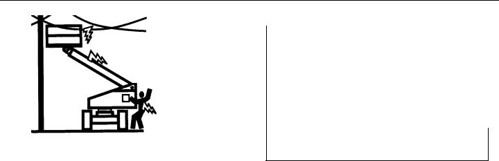
Electrocution Hazards
•This machine is not insulated and does not provide protection from contact or proximity to electrical current.
1-4 |
– JLG Lift – |
3121156 |
SECTION 1 - SAFETY PRECAUTIONS
•Maintain distance from electrical lines, apparatus, or any energized (exposed or insulated) parts according to the Minimum Approach Distance (MAD) as shown in Table 1- 1.
•Allow for machine movement and electrical line swaying.
Table 1-1. Minimum Approach Distances (M.A.D.)
Voltage Range |
MINIMUM APPROACH DISTANCE |
(Phase to Phase) |
in Feet (Meters) |
|
|
0 to 50 KV |
10 (3) |
|
|
Over 50KV to 200 KV |
15 (5) |
|
|
Over 200 KV to 350 KV |
20 (6) |
|
|
Over 350 KV to 500 KV |
25 (8) |
|
|
Over 500 KV to 750 KV |
35 (11) |
|
|
Over 750 KV to 1000 KV |
45 (14) |
|
|
NOTE: This requirement shall apply except where employer, local or governmental regulations are more stringent.
•Maintain a clearance of at least 10 ft. (3m) between any part of the machine and its occupants, their tools, and their equipment from any electrical line or apparatus carrying up to 50,000 volts. One foot additional clearance is required for every additional 30,000 volts or less.
3121156 |
– JLG Lift – |
1-5 |

SECTION 1 - SAFETY PRECAUTIONS
•The minimum approach distance may be reduced if insulating barriers are installed to prevent contact, and the barriers are rated for the voltage of the line being guarded. These barriers shall not be part of (or attached to) the machine. The minimum approach distance shall be reduced to a distance within the designed working dimensions of the insulating barrier. This determination shall be made by a qualified person in accordance with the employer, local, or governmental requirements for work practices near energized equipment
DO NOT MANEUVER MACHINE OR PERSONNEL INSIDE PROHIBITED ZONE (MAD). ASSUME ALL ELECTRICAL PARTS AND WIRING ARE ENERGIZED UNLESS KNOWN OTHERWISE.
Tipping Hazards
•The user should be familiar with the surface before driving. Do not exceed the allowable sideslope and grade while driving.
1-6 |
– JLG Lift – |
3121156 |

SECTION 1 - SAFETY PRECAUTIONS
•Do not elevate platform or drive with platform elevated while on a sloping, uneven, or soft surface.
•Before driving on floors, bridges, trucks, and other surfaces, check allowable capacity of the surfaces.
•Never exceed the maximum platform capacity. Distribute loads evenly on platform floor.
•Do not raise the platform or drive from an elevated position unless the machine is on firm, level and smooth surfaces.
•Keep the chassis of the machine at least 2 ft. (0.6m) from holes, bumps, drop-offs, obstructions, debris, concealed holes, and other potential hazards on the floor/surface.
•Do not push or pull any object with the boom.
•Never attempt to use the machine as a crane. Do not tieoff machine to any adjacent structure.
•Do not operate the machine when wind conditions exceed 28 mph (12.5 m/s). Refer to Table 1-2, Beaufort Scale (For Reference Only).
•Do not increase the surface area of the platform or the load. Increase of the area exposed to the wind will decrease stability.
•Do not increase the platform size with unauthorized deck extensions or attachments.
•If boom assembly or platform is in a position that one or more wheels are off the ground, all persons must be removed before attempting to stabilize the machine. Use cranes, forklift trucks, or other appropriate equipment to stabilize machine.
Crushing and Collision Hazards
•Approved head gear must be worn by all operating and ground personnel.
•Check work area for clearances overhead, on sides, and bottom of platform when lifting or lowering platform, and driving.
•During operation, keep all body parts inside platform railing.
3121156 |
– JLG Lift – |
1-7 |

SECTION 1 - SAFETY PRECAUTIONS
•Use the boom functions, not the drive function, to position the platform close to obstacles.
•Always post a lookout when driving in areas where vision is obstructed.
•Keep non-operating personnel at least 6 ft. (1.8m) away from machine during all driving and swing operations.
•Limit travel speed according to conditions of ground surface, congestion, visibility, slope, location of personnel, and other factors which may cause collision or injury to personnel.
•Be aware of stopping distances in all drive speeds. When driving in high speed, switch to low speed before stopping. Travel grades in low speed only.
•Do not use high speed drive in restricted or close quarters or when driving in reverse.
•Exercise extreme caution at all times to prevent obstacles from striking or interfering with operating controls and persons in the platform.
•Be sure that operators of other overhead and floor level machines are aware of the aerial work platform’s presence. Disconnect power to overhead cranes.
•Warn personnel not to work, stand, or walk under a raised boom or platform. Position barricades on floor if necessary.
1.4TOWING, LIFTING, AND HAULING
•Never allow personnel in platform while towing, lifting, or hauling.
•This machine should not be towed, except in the event of emergency, malfunction, power failure, or loading/unloading. Refer to the Emergency Procedures section of this manual for emergency towing procedures.
•Ensure boom is in the stowed position and the turntable locked prior to towing, lifting or hauling. The platform must be completely empty of tools.
•When lifting machine, lift only at designated areas of the machine. Lift the unit with equipment of adequate capacity.
•Refer to the Machine Operation section of this manual for lifting information.
1-8 |
– JLG Lift – |
3121156 |

SECTION 1 - SAFETY PRECAUTIONS
1.5ADDITIONAL HAZARDS / SAFETY
•Do not use machine as a ground for welding.
•When performing welding or metal cutting operations, precautions must be taken to protect the chassis from direct exposure to weld and metal cutting spatter.
•Do not refuel the machine with the engine running.
•Battery fluid is highly corrosive. Avoid contact with skin and clothing at all times.
•Charge batteries only in a well ventilated area.
3121156 |
– JLG Lift – |
1-9 |

SECTION 1 - SAFETY PRECAUTIONS
DO NOT OPERATE THE MACHINE WHEN WIND CONDITIONS EXCEED 28
MPH (12.5 M/S).
|
|
|
Table 1-2. Beaufort Scale (For Reference Only) |
||
|
|
|
|
|
|
Beaufort |
Wind Speed |
|
Description |
Land Conditions |
|
Number |
|
|
|
||
mph |
m/s |
|
|||
|
|
|
|||
|
|
|
|
|
|
0 |
0 |
0-0.2 |
|
Calm |
Calm. Smoke rises vertically |
|
|
|
|
|
|
1 |
1-3 |
0.3-1.5 |
|
Light air |
Wind motion visible in smoke |
|
|
|
|
|
|
2 |
4-7 |
1.6-3.3 |
|
Light breeze |
Wind felt on exposed skin. Leaves rustle |
|
|
|
|
|
|
3 |
8-12 |
3.4-5.4 |
|
Gentle breeze |
Leaves and smaller twigs in constant motion |
|
|
|
|
|
|
4 |
13-18 |
5.5-7.9 |
|
Moderate breeze |
Dust and loose paper raised. Small branches begin to move. |
|
|
|
|
|
|
5 |
19-24 |
8.0-10.7 |
|
Fresh breeze |
Smaller trees sway. |
|
|
|
|
|
|
6 |
25-31 |
10.8-13.8 |
|
Strong breeze |
Large branches in motion. Whistling heard in overhead wires. |
|
|
|
|
|
Umbrella use becomes difficult. |
|
|
|
|
|
|
7 |
32-38 |
13.9-17.1 |
|
Near Gale/Moderate Gale |
Whole trees in motion. Effort needed to walk against the wind. |
|
|
|
|
|
|
8 |
39-46 |
17.2-20.7 |
|
Fresh Gale |
Twigs broken from trees. Cars veer on road. |
|
|
|
|
|
|
9 |
47-54 |
20.8-24.4 |
|
Strong Gale |
Light structure damage. |
|
|
|
|
|
|
1-10 |
– JLG Lift – |
3121156 |
SECTION 2 - USER RESPONSIBILITIES, MACHINE PREPARATION, AND INSPECTION
SECTION 2. USER RESPONSIBILITIES, MACHINE PREPARATION, AND INSPECTION
2.1 PERSONNEL TRAINING
The aerial platform is a personnel handling device; so it is necessary that it be operated and maintained only by trained personnel.
Persons under the influence of drugs or alcohol or who are subject to seizures, dizziness or loss of physical control must not operate this machine.
Operator Training
Operator training must cover:
1.Use and limitations of the controls in the platform and at the ground, emergency controls and safety systems.
2.Control labels, instructions, and warnings on the machine.
3.Rules of the employer and government regulations.
4.Use of approved fall protection device.
5.Enough knowledge of the mechanical operation of the machine to recognize a malfunction or potential malfunction.
6.The safest means to operate the machine where overhead obstructions, other moving equipment, and obstacles, depressions, holes, drop-offs.
7.Means to avoid the hazards of unprotected electrical conductors.
8.Specific job requirements or machine application.
Training Supervision
Training must be done under the supervision of a qualified person in an open area free of obstructions until the trainee has developed the ability to safely control and operate the machine.
Operator Responsibility
The operator must be instructed that he/she has the responsibility and authority to shut down the machine in case of a malfunction or other unsafe condition of either the machine or the job site.
3121156 |
– JLG Lift – |
2-1 |

SECTION 2 - USER RESPONSIBILITIES, MACHINE PREPARATION, AND INSPECTION
2.2 PREPARATION, INSPECTION, AND MAINTENANCE
The following table covers the periodic machine inspections and maintenance required by JLG Industries, Inc. Consult local regulations for further requirements for aerial work platforms. The frequency of inspections and maintenance must be increased as necessary when the machine is used in a harsh or hostile environment, if the machine is used with increased frequency, or if the machine is used in a severe manner.
JLG INDUSTRIES, INC. RECOGNIZES A FACTORY-TRAINED SERVICE TECHNICIAN AS A PERSON WHO HAS SUCCESSFULLY COMPLETED THE JLG SERVICE TRAINING SCHOOL FOR THE SPECIFIC JLG PRODUCT MODEL.
2-2 |
– JLG Lift – |
3121156 |

SECTION 2 - USER RESPONSIBILITIES, MACHINE PREPARATION, AND INSPECTION
Table 2-1.Inspection and Maintenance Table
Type |
Frequency |
Primary |
Service |
Reference |
|
Responsibility |
Qualification |
||||
|
|
|
|||
|
|
|
|
|
|
Pre-Start Inspection |
Before using each day; or |
User or Operator |
User or Operator |
Operator and Safety Manual |
|
|
whenever there’s an Operator change. |
|
|
|
|
|
|
|
|
|
|
Pre-Delivery Inspection |
Before each sale, lease, or rental delivery. |
Owner, Dealer, or User |
Qualified JLG |
Service and Maintenance |
|
(See Note) |
|
|
Mechanic |
Manual and applicable JLG |
|
|
|
|
|
inspection form |
|
|
|
|
|
|
|
Frequent Inspection |
In service for 3 months or 150 hours, whichever |
Owner, Dealer, or User |
Qualified JLG |
Service and Maintenance |
|
(See Note) |
comes first; |
|
Mechanic |
Manual and applicable JLG |
|
|
or |
|
|
inspection form |
|
|
Out of service for a period of more than 3 months; |
|
|
|
|
|
or |
|
|
|
|
|
Purchased used. |
|
|
|
|
|
|
|
|
|
|
Annual Machine Inspection |
Annually, no later than 13 months from the date |
Owner, Dealer, or User |
Factory-Trained |
Service and Maintenance |
|
(See Note) |
of prior inspection. |
|
Service Technician |
Manual and applicable JLG |
|
|
|
|
(Recommended) |
inspection form |
|
|
|
|
|
|
|
Preventative Maintenance |
At intervals as specified in the Service and Main- |
Owner, Dealer, or User |
Qualified JLG |
Service and Maintenance |
|
|
tenance Manual. |
|
Mechanic |
Manual |
|
|
|
|
|
|
NOTE: Inspection forms are available from JLG. Use the Service and Maintenance Manual to perform inspections.
3121156 |
– JLG Lift – |
2-3 |
SECTION 2 - USER RESPONSIBILITIES, MACHINE PREPARATION, AND INSPECTION
Pre-Start Inspection
The Pre-Start Inspection should include each of the following:
1.Cleanliness – Check all surfaces for leakage (oil, fuel, or battery fluid) or foreign objects. Report any leakage to the proper maintenance personnel.
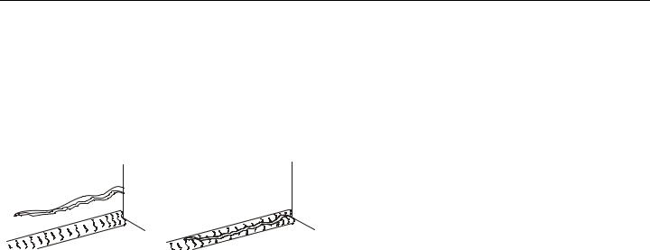
2.Structure - Inspect the machine structure for dents, damage, weld or parent metal cracks or other discrepancies.
Parent Metal Crack |
Weld Crack |
3.Decals and Placards – Check all for cleanliness and legibility. Make sure none of the decals and placards are missing. Make sure all illegible decals and placards are cleaned or replaced.
4.Operators and Safety Manuals – Make sure a copy of the Operator and Safety Manual, AEM Safety Manual (Domestic only), and ANSI Manual of Responsibilities
(Domestic only) is enclosed in the weather resistant storage container.
5.“Walk-Around” Inspection – Refer to Figure 2-4., Figure 2-6. and Figure 2-7.
6.Battery – Charge as required.
7.Fuel (Combustion Engine Powered Machines) – Add the proper fuel as necessary.
8.Engine Oil Supply - Ensure the engine oil level is at the Full mark on the dipstick and the filler cap is secure.
9.Hydraulic Oil – Check the hydraulic oil level. Ensure hydraulic oil is added as required.
10.Accessories/Attachments - Reference the Operator and Safety Manual of each attachment or accessory installed upon the machine for specific inspection, operation, and maintenance instructions.
11.Function Check – Once the “Walk-Around” Inspection is complete, perform a functional check of all systems in an area free of overhead and ground level obstructions. Refer to Section 4 for more specific operating instruc- tions.
2-4 |
– JLG Lift – |
3121156 |

SECTION 2 - USER RESPONSIBILITIES, MACHINE PREPARATION, AND INSPECTION
IF THE MACHINE DOES NOT OPERATE PROPERLY, TURN OFF THE MACHINE IMMEDIATELY! REPORT THE PROBLEM TO THE PROPER MAINTENANCE PERSONNEL. DO NOT OPERATE THE MACHINE UNTIL IT IS DECLARED SAFE FOR OPERATION.
Daily Functional Check
A functional check of all systems should be performed, once the walk-around inspection is complete, in an area free of overhead and ground level obstructions. First, using the ground controls, check all functions controlled by the ground controls. Next, using the platform controls, check all functions controlled by the platform controls.
TO AVOID SERIOUS INJURY, DO NOT OPERATE MACHINE IF ANY CONTROL LEVERS OR TOGGLE SWITCHES CONTROLLING PLATFORM MOVEMENTS DO NOT RETURN TO THE OFF OR NEUTRAL POSITION WHEN RELEASED.
TO AVOID COLLISION AND INJURY IF PLATFORM DOES NOT STOP WHEN A CONTROL SWITCH OR LEVER IS RELEASED, REMOVE FOOT FROM FOOTSWITCH OR USE EMERGENCY STOP TO STOP THE MACHINE.
NOTE: Perform checks from ground controls first, then from platform controls.
1. Operate machine from ground control.
NOTE: For adjustments see Service Manual, Limit Switch Adjustments.
2.Check elevation limit switch as follows:
While driving in high drive, elevate the boom to approximately 10 degrees. Drive should cut back to low speed. The switch should reset when the boom is fully lowered.
3.Check capacity limit switch as follows:
a.Boom Length Switch.
Raise boom to horizontal. Telescope boom out until 500 lb. light comes on. Make sure the switch resets and the 1000 lb. light comes back on when telescoping in.
b.Boom Angle Switch.
Telescope boom to full extension.
Lift boom up until 1000 lb. light comes on.
Lift boom down using auxiliary power until 500 lb.
3121156 |
– JLG Lift – |
2-5 |

SECTION 2 - USER RESPONSIBILITIES, MACHINE PREPARATION, AND INSPECTION
light comes on. Boom angle must be approximately 45 to 50 degrees
Lift boom up until 1000 lb. light comes on. The switch should reset when the boom angle is about 55 degrees to 64 degrees.
NOTE: If limit switch settings need to be changed, you will need to recheck that the 500 lb. light comes on at 45 degrees to 50 degrees when lifting down.
4.Drive Disable Switch (Refer to Figure 2-2., Drive Function Operating Range Diagrams - Sheet 2 of 3).
a.Telescope the boom out over 40 ft. (12.2 m).
b.Manually tilt the tilt sensor.
c.Drive Disable Indicator Light should come on.
d.Retract the boom and elevate to at least 55°.
e.Manually tilt the tilt sensor.
f.The Drive Disable Indicator Light should come on again.
5.Raise main boom, extend and retract telescope. Check for delayed movement of fly section, indicating loose cables.
NOTE: Turntable lock is on turntable facing platform. To disengage lock, pull snap pin from lock pin, lift lock pin up to
|
unlock turntable. Return snap pin to lock pin to hold lock |
||||
|
pin in the disengaged position. Reverse procedure to |
||||
|
engage turntable lock. |
|
|
||
6. |
Swing turntable to LEFT and RIGHT a minimum of 45 |
||||
|
degrees. Check for smooth motion. |
|
|
||
7. |
Check the chassis out of level indicator located on the |
||||
|
platform control console by driving, with the machine in |
||||
|
level position, up a suitable ramp of at least 5° slope. |
||||
|
Check the out of level indicator, with the machine on the |
||||
|
ramp. If the light does not illuminate, return the machine |
||||
|
to a level surface, shut down the machine, and contact a |
||||
|
qualified technician before resuming operation. |
||||
|
|
|
|
|
|
|
|
ANSI, ANSI Export, CSA, Japan |
|
5° |
|
|
|
|
|
|
|
|
|
CE, Australia |
|
3° |
|
|
|
|
|
|
|
8. |
Check that platform automatic self-leveling system func- |
||||
|
tions properly during raising and lowering of the boom. |
||||
9. |
Check platform level adjustment system for proper oper- |
||||
|
ation. |
|
|
||
10. |
Check platform rotator for smooth operation and assure |
||||
|
platform will rotate 90 degrees in both directions from |
||||
|
centerline of boom. |
|
|
||
2-6 |
– JLG Lift – |
3121156 |

SECTION 2 - USER RESPONSIBILITIES, MACHINE PREPARATION, AND INSPECTION
11.Drive forward and reverse; check for proper operation.
12.Steer left and right; check for proper operation.
13.Raise and lower Articulating Jib Boom. Check for smooth operation.
14.Footswitch.
FOOTSWITCH MUST BE ADJUSTED SO THAT FUNCTIONS WILL OPERATE WHEN PEDAL IS APPROXIMATELY AT ITS CENTER OF TRAVEL. IF SWITCH OPERATES WITHIN LAST 1/4" OF TRAVEL, TOP OR BOTTOM, IT SHOULD BE ADJUSTED.
a.Activate hydraulic system. By depressing footswitch. Operate MAIN TELESCOPE and hold control. Remove foot from footswitch, motion should stop. If it does not, shut down machine and contact a certified JLG service technician.
b.With footswitch depressed, operate LIFT and hold control. Remove foot from footswitch, motion should stop. If it does not, shut down machine and contact a certified JLG service technician.
c.With engine power shut down, depress the footswitch. Attempt to start engine. Engine should not attempt to start when footswitch is depressed. If starter engages or engine turns over, shut down machine and contact a certified JLG service technician.
15.Auxiliary Power.
Operate each function control switch (e.g. TELE, LIFT and SWING) to assure that they function in both directions using auxiliary power instead of engine power.
16.Ground Controls.
Place GROUND/PLATFORM SELECT switch to GROUND. Start engine. Platform controls should not operate.
3121156 |
– JLG Lift – |
2-7 |

SECTION 2 - USER RESPONSIBILITIES, MACHINE PREPARATION, AND INSPECTION
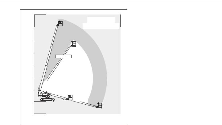
NOTE: In the Transport Mode, High Drive will be disabled above 10° elevation or past 3 feet (1 m) of boom extension.
Figure 2-1. Drive Function Operating Range Diagrams - Sheet 1 of 3
2-8 |
– JLG Lift – |
3121156 |
SECTION 2 - USER RESPONSIBILITIES, MACHINE PREPARATION, AND INSPECTION
70ft. |
|
|
|
|
|
|
|
21.34 m |
|
|
|
CHASSIS |
|
|
|
18.29 m |
NO DRIVE IF |
|
|
|
|||
TILTED> 1.8° |
|
||||||
60ft. |
|
|
|
|
|
|
|
|
CHASSIS |
|
|
|
|
|
|
50ft. |
TILTED> 1.8° |
|
|
|
|
|
|
|
|
|
|
|
|
|
|
15.24 m |
|
|
|
|
|
|
|
40ft. |
|
|
|
|
|
|
|
12.19 m |
55 DEGREES |
|
|
|
|
|
|
|
|
|
|
NOTE: In the Transport Mode, High Drive will |
|||
30ft. |
|
|
|
|
|
||
|
|
|
|
|
be |
disabled above 10° elevation or |
|
9.14 m |
|
|
|
|
|
past 3 feet (1 m) of boom extension. |
|
|
|
|
|
|
|
||
20ft. |
DRIVE CUTOUT |
|
|
|
|
||
|
PER |
|
|
|
|
|
|
6.10 m |
|
|
|
|
|
|
|
PERSONALITY |
|
|
|
|
|||
|
|
|
|
|
|||
10ft. |
|
SETTING |
|
|
|
|
|
|
|
|
|
|
|
|
|
3.05 m |
|
|
|
|
|
|
|
0 |
|
|
|
|
|
|
|
10ft. |
|
|
|
|
|
|
|
3.05 m |
10ft. |
20ft. |
30ft. |
40ft. |
50ft. |
60ft. |
|
|
|
||||||
|
3.05 m |
6.10 m |
9.14 m |
12.19 m |
15.24 m |
18.29 m |
|
Figure 2-2. Drive Function Operating Range Diagrams - Sheet 2 of 3
3121156 |
– JLG Lift – |
2-9 |

SECTION 2 - USER RESPONSIBILITIES, MACHINE PREPARATION, AND INSPECTION
70ft. |
|
|
|
|
|
|
|
21.34 m |
|
|
|
|
|
|
|
60ft. |
|
|
|
CHASSIS |
|
||
18.29 m |
CREEP IF |
|
TILTED |
|
|
||
|
TILTED > 1.8° |
|
|
|
|||
50ft. |
CUTOUTS PER |
|
|
|
|
|
|
PERSONALITY SETTING |
|
|
|
|
|||
15.24 m |
|
|
|
|
|
|
|
40ft. |
|
|
|
|
|
|
|
12.19 m |
55 DEGREES |
|
|
|
|
|
|
|
|
|
|
NOTE: |
In the Transport Mode, High Drive will |
||
30ft. |
|
|
|
|
|
||
|
|
|
|
|
|
be disabled above 10° elevation or |
|
9.14 m |
|
|
|
|
|
|
|
|
|
|
|
|
|
past 3 feet (1 m) of boom extension. |
|
|
|
|
|
|
|
|
|
20ft. |
CREEP CUTOUTS |
|
|
|
|
||
6.10 m |
PER PERSONALITY |
|
|
|
|
||
|
|
SETTING |
|
|
|
|
|
10ft. |
|
|
|
|
|
|
|
3.05 m |
|
|
|
|
|
|
|
0 |
|
|
|
|
|
|
|
10ft. |
|
|
|
|
|
|
|
3.05 m |
10ft. |
20ft. |
30ft. |
40ft. |
50ft. |
60ft. |
|
|
|
||||||
|
3.05 m |
6.10 m |
9.14 m |
12.19 m |
15.24 m |
18.29 m |
|
Figure 2-3. Drive Function Operating Range Diagrams - Sheet 3 of 3
2-10 |
– JLG Lift – |
3121156 |
 Loading...