


JLG X23J, X700AJ Operator Manual
Operation, Safety, Maintenance
and service Manual
Original Instructions - Keep this manual with the machine at all times.
Boom Lift Models
X23J
X23JR062
January, 2013


JLG LIFT
FOREWORD
For:
• Accident Reporting
• Product Safety Publications
• Current Owner Updates
• Questions Regarding Product Safety
• Standards and Regulations Compliance Information
• Questions Regarding Special Product Applications
• Questions Regarding Product Modifications
Contact:
Product Safety and Reliability Department
JLG Industries, Inc.
13224 Fountainhead Plaza
Hagerstown, MD 21742
or Your Local JLG Office
(See addresses on manual cover)
In USA:
Toll Free: 877‑JLG‑SAFE (877‑554‑7233)
Outside USA:
Phone: 240‑420‑2661
Fax: 301‑745‑3713
E‑mail: ProductSafety@JLG.com
X23JR062

X23JR062
REVISION LOG
Rev. Manual code Date
Original Issue X23JR002 January, 2011
01 X23JR012 February, 2011
02 X23JR022 February, 2011
03 X23JR032 March, 2011
04 X23JR042 March, 2012
05 X23JR052 December, 2012
06 X23JR062 January, 2013
JLG LIFT
FOREWORD

BOOM LIFT MODELS X23J
JLG
INDEX
CHAPTER 1 PRESENTATION ....................................................................................Page 08
CHAPTER 2 OPERATOR MANUAL .........................................................................Page 09
2.1 Description of the machine ...................................................................Page 09
2.1.1 Control position ......................................................................................Page 09
2.1.2 Machine identification plate .................................................................Page 12
2.1.3 Machine clearance ..................................................................................Page 13
2.1.4 Technical data..........................................................................................Page 14
2.1.4.1 Petrol engine technical data ..................................................................Page 15
2.1.4.2 Diesel engine technical data..................................................................Page 15
2.1.4.3 Hydraulic system technical data ..........................................................Page 15
2.1.4.4 Electric plant technical data ..................................................................Page 16
2.1.4.5 Electrical system technical specifications lithium..............................Page 16
2.1.5 Terminology ............................................................................................Page 17
2.1.6 Transport and stabilisation position (standard version)...................Page 21
2.2 General safety standards .......................................................................Page 22
2.3 Safety warnings.......................................................................................Page 26
2.3.1 Generalities..............................................................................................Page 26
2.3.2 Noise and vibrations ..............................................................................Page 26
2.3.3 Pictograms positioned on the machinea .............................................Page 27
CHAPTER 3 SAFETY DEVICES..................................................................................Page 40
3.1 Battery cut‑off..........................................................................................Page 41
3.2 Distributors over‑pressure valves ........................................................Page 41
3.3 Cylinder cut‑off valves...........................................................................Page 42
3.4 Alignment photocell of the aerial part of the structure and machine base ..Page 42
3.5 Outriggers position micro switches .....................................................Page 43
3.6 Jib position micro switch .......................................................................Page 45
3.7 Ropes integrity micro switch ................................................................Page 45
3.8 Basket load sensor ..................................................................................Page 45
3.9 Control protections.................................................................................Page 46
3.10 Spirit level ................................................................................................Page 46
3.11 Screws and nuts locking pins................................................................Page 47
3.12 Safety device control circuit board.......................................................Page 49
3.13 Outrigger joint lock pins........................................................................Page 50
3.14 Arms position sensors............................................................................Page 50
CHAPTER 4 INSTRUMENTS AND CONTROLS.....................................................Page 51
4.1 Remote control ........................................................................................Page 51
4.1.1 Display .....................................................................................................Page 52
4.1.1.1 Display main screen .................................................................................Page 52
4.1.2 Joystick .....................................................................................................Page 57
4.1.3 Buttons ......................................................................................................Page 59
4.2 Footswitch.................................................................................................Page 63
4.3 Control positions ......................................................................................Page 63
CHAPTER 5 EMERGENCY DEVICES .......................................................................Page 64
5.1 Emergency stop button..........................................................................Page 64
5.2 Hand pump .............................................................................................Page 65
5.3 Solenoid valves for emergency descent...............................................Page 65
5.4 Safety devices by‑pass key ....................................................................Page 65
5.5 Emergency position control ..................................................................Page 66
CHAPTER 6 MACHINE USE ......................................................................................Page 72
6.1 Safety standards to adopt before using the platform ................................Page 72
6.1.1 Electrocution hazard ..............................................................................Page 72
6.1.2 Danger due to atmospheric conditions ...............................................Page 72
6.1.3 Danger due to the work area ................................................................Page 73
6.2 Procedures for correct use.....................................................................Page 73
6.2.1 Summary table of the safety standards for the operator ................Page 73
1
X23JR0620113

6.3 Working area...........................................................................................Page 75
6.4 Use of the elevating work platform (MEWP).....................................Page 76
6.4.1 Preliminary checks before starting work ............................................Page 77
6.4.2 Starting the petrol and diesel engine ..................................................Page 78
6.4.3 Starting the electric engine ....................................................................Page 79
6.4.4 Engine turning‑of....................................................................................Page 81
6.4.5 Stopping the motor lithium version.....................................................Page 81
6.4.6 Operative load automatic selection......................................................Page 82
6.4.7 Passage from transport configuration to stabilisation
configuration Standard version............................................................Page 82
6.4.8 Traversing ................................................................................................Page 86
6.4.9 Jib arm movement for traversing .........................................................Page 88
6.4.10 Parking the machine on slopes or on uneven ground.......................Page 90
6.4.11 Stabilising and levelling the machine..................................................Page 90
6.4.12 Automatic stabilization and destabilization.......................................Page 94
6.4.13 Track widening........................................................................................Page 96
6.4.14 Basket movement....................................................................................Page 96
6.4.15 Manual levelling of the cage .................................................................Page 102
6.5 Aerial part emergency manoeuvres.....................................................Page 104
6.5.1 Activation of emergency descent from the basket.............................Page 104
6.5.2 Manoeuvre of the machine from the emergency position on the
ground in the case of sudden indisposition of the operator ............Page 105
6.5.3 Activation of the emergency descent in the case of accidental
destabilisation of the machine ..............................................................Page 106
6.5.4 Activation of the emergency descent from the ground in case of operator
indisposition, engine functioning and electric plant broken down.......Page 108
6.5.5 Activation of the emergency descent from the ground with manual
pump if all energy systems should break down ...............................Page 110
6.5.6 Track part emergency manoeuvre: movement of the platform
outriggers with manual pump to allow machine tran sport............Page 112
6.5.7 The manoeuvre illustrated successively must only be performed
with the machine closed ........................................................................Page 113
6.6 Electrical disconnection of the remote control ...................................Page 116
6.7 Recharging the battery...........................................................................Page 117
6.8 Main declared uses of the platform .....................................................Page 121
6.8.1 Plant engineering....................................................................................Page 121
6.8.2 Closed rooms...........................................................................................Page 121
6.8.3 Use for pruning.......................................................................................Page 121
6.8.4 Use for repair and maintenance of roofs and gutters........................Page 122
6.8.5 Use for painting, sanding and plastering............................................Page 122
6.8.6 Use in marine environment...................................................................Page 122
CHAPTER 7 MAINTENANCE....................................................................................Page 123
7.1 Greasing and lubrication specifications ..............................................Page 123
7.2 Table of recommended lubricants ........................................................Page 123
7.3 Greasing points .......................................................................................Page 125
7.4 Greasing the telescopic extension arm ................................................Page 125
7.5 Maintenance safety regulations............................................................Page 126
7.6 Manoeuvre of the machine from the second emergency position from the ground through
the optional second remote control in case of maintenance operations ......Page 127
7.7 Periodic maintenance limits..................................................................Page 128
7.8 Electric motor ..........................................................................................Page 131
7.8.1 Electric motor maintenance...................................................................Page 131
7.9 Inspection and maintenance .................................................................Page 132
7.10 General periodic control ........................................................................Page 134
7.11 Rubber track maintenance.....................................................................Page 135
7.11.1 Checking track tension...........................................................................Page 135
7.11.2 Operations for loosening/tightening the track ...................................Page 135
7.11.3 Checking the rubber tracks ...................................................................Page 136
7.11.4 Replacing the rubber tracks ..................................................................Page 138
2
X23JR0620113
BOOM LIFT MODELS X23J
JLG

3
7.12 Checking tightness of nuts and bolts...................................................Page 139
7.13 Checking hydraulic oil level .................................................................Page 144
7.13.1 Hydraulic oil............................................................................................Page 144
7.14 Checking leakage from the hydraulic system ....................................Page 144
7.15 Checking the status of the filtering cartridge .....................................Page 144
7.16 Checking the presence and integrity of the machine plates ............Page 145
7.17 Checking the working pressures of the hydraulic system ...............Page 145
7.18 Checking tightness of the screw fasteners of the pin retainers
and the locknuts......................................................................................Page 146
7.19 Replacing/checking extension ropes and pulleys ..............................Page 146
7.19.1 Checking wear and deformation of ropes and pulleys.....................Page 147
7.20 Three‑monthly inspection .....................................................................Page 148
7.21 Five‑year inspection ...............................................................................Page 150
7.22 Checking wear of the telescopic arm slide blocks .............................Page 150
7.23 Checking extension pulley wear ..........................................................Page 151
7.24 Checking tightness of the coupling element screws..........................Page 151
7.25 Battery: checks and maintenance thermic version.............................Page 151
7.25.1 Checking the electrolyte thermic version............................................Page 151
7.25.2 Re‑charging the battery thermic version.............................................Page 152
7.25.3 Replacing the battery thermic version.................................................Page 153
7.25.4 Disposal of the battery ...........................................................................Page 153
7.26 Battery pack operating specifications..................................................Page 153
7.26.1 Components and diagrams ...................................................................Page 154
7.26.2 Personal protective equipment.............................................................Page 156
7.26.3 Handling in dangerous conditions ......................................................Page 156
7.26.3.1 Procedure for handling hot cells ..........................................................Page 156
7.26.3.2 Procedure for handling vented cells....................................................Page 157
7.26.3.3 Procedure for exploded cells.................................................................Page 159
7.26.3.4 Lithium battery fire ................................................................................Page 160
7.27 Engine maintenance thermic version ..................................................Page 162
CHAPTER 8 SAFETY STANDARDS REGARDING TRANSPORT .......................Page 162
8.1 Removing the basket..............................................................................Page 162
8.2 Safety standards regarding transport..................................................Page 163
8.3 Lifting the machine.................................................................................Page 164
8.3.1 How and where to attach the platform ...............................................Page 165
8.3.2 What to use to attach the platform.......................................................Page 165
8.4 Transporting the machine......................................................................Page 166
CHAPTER 9 REMOTE CONTROL SERVICE MENU ..............................................Page 168
9.1 Menu' input .............................................................................................Page 168
9.2 Errors menu.............................................................................................Page 170
9.3 Working hours menu .............................................................................Page 170
9.4 Set‑up menu ............................................................................................Page 170
9.5 Joystick menu ..........................................................................................Page 170
CHAPTER 10 TROUBLESHOOTING...........................................................................Page 171
CHAPTER 11 CHECKS TO MAKE ON THE MACHINE AFTER REPAIRS..........Page 178
11.1 Checking the correct functioning of controls .....................................Page 178
11.2 Checking functioning of the safety devices ........................................Page 178
CHAPTER 12 HYDRAULIC SYSTEM..........................................................................Page 179
12.1 Hydraulic system diagram thermic version.......................................Page 179
12.2 Key to the hydraulic system diagram thermic version.....................Page 181
12.3 Hydraulic system diagram lithium version........................................Page 182
12.4 Key to the hydraulic system diagram lithium version........................Page 184
CHAPTER 13 ELECTRIC PLANT.................................................................................Page 185
13.1 Electric plant thermic version ...............................................................Page 185
13.2 Electric plant lithium version................................................................Page 187
BOOM LIFT MODELS X23J
JLG
X23JR0620113
PREFACE
The scope of this manual is to supply the user with the necessary instructions and indispen‑
sable operational procedures in order to favour the correct and safe use of the machine for
the objectives to which it is destined and to prevent serious injury to the operator and others.
IMPORTANT
ALL INFORMATION PRESENTED IN THIS MANUAL IS UNQUESTIONABLE AND IT
MUST BE READ CAREFULLY AND UNDERSTOOD BEFORE MAKING ANY MANOEU‑
VRES WITH THE MACHINE.
As this manual is the most important work instrument, it must always be kept in the machi‑
ne, in the relevant compartment, in order to always be available at any time for clarifications.
As it is impossible for the manufacturer to check the status of the machine and the opera‑
tions it performs THE USER IS RESPONSIBLE for compliance with the safety procedures
described in this manual.
Every machine is adjusted and inspected scrupulously before delivery so that the operator
does not have to perform adjustments.
Every alteration and/or modification of the features of the original machine design without
previous written authorisation from the Constructor are PROHIBITED and THE RESPONSI‑
BILITY FOR THESE ACTIONS FALLS ON THE OPERATOR.
THE EMPLOYER MUST CHECK THAT THE OPERATOR HAS THE VOCATIONAL
REQUISITES NECESSARY FOR RUNNING THE MACHINE CORRECTLY AND THAT
HE HAS CAREFULLY EXAMINED AND UNDERSTOOD THAT STATED IN THIS USE
AND MAINTENANCE MANUAL, RECEIVING SUITABLE TRAINING REGARDING
USE OF THE MACHINE IN STANDARD AND EMERGENCY CONDITIONS.
THE EMPLOYER MUST ALSO TRAIN THE OPERATORS REGARDING ANY NATIO‑
NAL STANDARDS THAT COMMEWSTE THAT CONTAINED IN THIS DOCUMENT.
If the manual is damaged or lost, a copy must be requested directly from JLG.
Note: All of the photos and drawings inserted in this manual have been added to ease
comprehension by the reader. The machine you own may differ from some parts of the
photos and drawings given.
BOOM LIFT MODELS X23J
JLG
4
X23JR0620113

5
NORMATIVE REFERENCES
The machine has been designed, built and inspected according to that prescribed in the EN280
prA2:2009 harmonised standard, which supplies the presumption of conformity with the Essen‑
tial Safety Requisites of the 2006/42/CE Machinery Directive even if a type C Voluntary Technical
Standard.
According to that stated in EN280 prA2, the JLG platform is classified in GROUP B, as the
vertical projection of the centre of gravity of the load can be outside of the tilting lines and in
TYPE 1 as traversing is only allowed with the platform at rest.
The stability tests of the machine have been made in accordance with what described in
paragraph 6.1.4.2 of the EN280 with load test calculated in conformity with 5.2.4 and have
been successful.
In addition what prescribed in this manual it is necessary to apply the technical requirements of
the following national/international safety standards:
‑ UNI ISO 18893
‑ ISO 16368
‑ ISO 18878
With the exception of stricter local or national regulations in the working area of the MEWP.
WARRANTY
On purchasing a JLG platform, a warranty and inspection certificate is issued that clearly
indicates the warranty terms and where any interventions on the machine must be reported.
LIABILITY
The Constructor is exonerated from any liability and obligation for any injury/damage cau‑
sed to persons/objects due to any of the reasons listed below:
• Failure to comply with the instructions indicated in this USE AND MAINTENANCE
MANUAL regarding running, use and maintenance of the machine;
• Violent or sudden actions or incorrect manoeuvres when using or servicing the machine;
• Modifications made to the structure or machine components without previous authori‑
sation from the Constructor and/or without the use of suitable equipment;
• Strange events with respect to normal and correct use of the machine, described in this
USE AND MAINTENANCE MANUAL.
• Use of non‑original spare parts not authorised by the manufacturer.
BOOM LIFT MODELS X23J
JLG
X23JR0620113

EC DECLARATION OF CONFORMITY
BOOM LIFT MODELS X23J
JLG
6
X23JR0620113
EC DECLARATION OF
CONFORMITY
Manufacturer
Address
Technical File:
Authorised contact
Machine Type:
Model Type: ...
Serial Number:
Notified Body:
EC Number:
Address
JLG Industries Inc
1 JLG Drive
McConnellsburg
PA17233
USA
JLG Industries Inc
JLG Technology & Development Centre
Bruntingthorpe Aerodrome & Proving Ground
Lutterworth, Leicestershire
LE17 5QS
United Kingdom.
Alan S. McInt
Mobile Elevating Work Platform
...
ECO Certificazioni S.p.A
0714
Via Mengollna
33 - 48108
Faenza
Italy
yre
Position:
Manager, Engineering
Support - Europe
Certificate Number:
Reference Standards:
JLG Industries hereby declare that the above mentioned machine conforms
with the requirements of:
2006/42/EC Machiner
2004/108/EC EMC Directive
2000/14/EC Outdoor Noise
Signed:
Name: Alan S. McIntyre Position: Manager,Engineering Support-
Remark:
An
y modification to the above described machine violates the validity of this declaration.
This declaration conforms with the requirements of annex II-A of the council directive
2006/42/EC
Machine manufactured for JLG Industries Inc. by HINOWA S.p.a via Fontana 37054
NOGARA VR Ital
y
To Be Advised
EN12100-1 & 2:2003 + A1:2009
EN280:2001 + A2:2009
y
Date: ...
Europe
Place: Bruntingthorpe, UK

7
BOOM LIFT MODELS X23J
JLG
X23JR0620113
y
y
EC DECLARATION OF
CONFORMITY
Manufacturer
Address
Machine Type:
Model Type:
Serial Number:
Document Control:
Measured
Lwa
Guaranteed
Lwa ...dB(A)
Engine Power:
...kW
Lwa = (Sound Power Level)
JLG Industries Inc
1 JLG Drive
McConnellsburg
PA17233
USA
Mobile Elevating Work Platform
...
...
HINOWA S.p.A
Via Fontana - 37054
Nogara
Italy
...dB(A)
Technical File:
JLG Industries Inc
JLG Technology &
Development Centre
Bruntingthorpe
Aerodrome & Proving
Ground
Lutterworth,
Leicestershire
LE17 5QS
United Kingdom.
Applicable Procedure:
Applicable Directive:
EN ISO 3744:1995
2000/14/EC Annex V Internal Control of Production.
We hereby declare that the above mentioned machine
conforms with the requirements of the "Noise Emission in
the Environment by Equipment for Use Outdoors"
Directive 2000/14/EC & 2005/88/EC
Remark:
This declaration conforms with the requirements of Annex II of the council directive
2000/14/EC
An
modification to the above described machine violates the validity of this declaration.
Machine manufactured for JLG Industries Inc. by HINOWA S.p.a via Fontana 37054
NOGARA VR Ital

1. PRESENTATION
This manual presents the warning signs used to bring the reader’s attention to several parti‑
cularly important warnings.
The safety warnings are divided into two main types, which are identified and described
below.
DANGER
This symbol accompanied by the word DANGER indicates that the situation
described, if not prevented, can lead to serious injury or death of the persons
involved (operator, ground staff, staff present in proximity of the platform, main‑
tenance technicians etc.).
ATTENTION
This symbol accompanied by the word ATTENTION indicates that the situation
described represents a potential risk for the structure of the machine. Dangerous
situations could be determined from this condition (also injury or death) for the
persons involved.
BOOM LIFT MODELS X23J
JLG
8
X23JR0620113

9
2. OPERATOR MANUAL
2.1. DESCRIPTION OF THE MACHINE
The JLG machine is a self‑propelled hydraulic lifting device, equipped with a rotating work
basket positioned at the top of an extendable articulated structure, which also rotates. The
JLG lifting device is destined for the POSITIONING OF PERSONS AND THEIR EQUIP‑
MENT AND MATERIALS IN HIGH POSITIONS WITH RESPECT TO GROUND LEVEL.
2.1.1 CONTROL POSITION
‑ CONTROL POSITION IN THE CAGE
The JLG overhead platform has been designed to be controlled by the operator in the basket
using a remote control, where all of the machine functional controls are gathered, positioned
in the relevant support inside the basket (see photo). A pedal button is also present in the
basket to allow movement of the aerial part (photo).From this control position it is possible
to control the extendible structure and machine stabilisation. When the machine is manoeu‑
vred from the control position in the basket, the remote control must be positioned in the
appropriate seat, and the footswitch must be pushed (the footswitch must be release and
pressed again if no movements are made for more of 7 second). The remote control is con‑
nected to the machine using a flexible cable that allows to shift it if the basket is to be remo‑
ved or the ground control unit is to be used.
Stabilisation of the machine must be preferably controlled from the basket drive position.
Machine traversing must be carried out from the control position on the ground.
After having reached or left the control position in the basket, ALWAYS remember to close
the ladder to avoid any damages during the use of the machine. After having left the con‑
trol position in the basket always remember to close the remote control protection cover.
BOOM LIFT MODELS X23J
JLG
X23JR0620113
ATTENTION
ATTENZIONE
CONTROL POSITION ON THE GROUND:
There is a second control position for the track part. This position is not fixed but is located
on the ground within a radius equal to 2.5m from the basket attachment. To control the
machine, use the same remote control present in the basket, which is withdrawn from its seat
and moved away from the basket using the free cable length available.
This control position IS NOT enabled to control the aerial part of the
machine, but only the trailers, outriggers and track widening.
ATTENTION: when controlling the machine from the ground position keep
at a distance of at least 1m from the tracks.
ATTENTION: when the machine is controlled from the ground position
always check there is complete visibility of the component that is
to be moved and its trajectory for the entire duration of the movement.
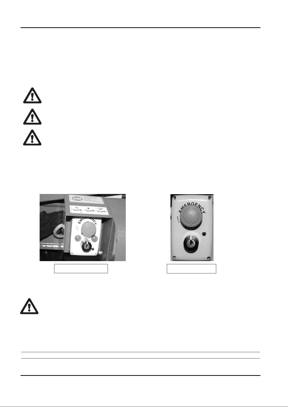
‑ EMERGENCY CONTROL POSITION
There is a control position that will be identified as the emergency control position. It is on
the part of the machine on the ground in correspondence with the aerial part distributor. To
enable, act on the relevant selector switch at the base of the turret (see photo) until the green
indicator switches on. This indicates movement enabling of the aerial part.
From here it is possible to make machine movements by acting directly on the levers present
on the various hydraulic distributor elements, aerial (see photo 1) and proportional areas
(aerial part see photo 2).
The emergency control position has been designed, to operate on the extendible structure
only for emergency manoeuvres by rescue staff on the ground, which must be trained and
have know‑how regarding the functioning of the machine and its safety devices, for main‑
tenance interventions and to perform checks before starting work.
It is prohibited to move the structure from the ground position, if someone is present in
the basket, unless it is an emergency situation (sudden indisposition of the operator, tech‑
BOOM LIFT MODELS X23J
JLG
10
X23JR0620113
ATTENTION
THERMIC MOTOR
LITHIUM MOTOR
ATTENZIONE

11
nical breakdown).
There is a control position usable only for operations of ordinary and extraordinary mainte‑
nance operations, position placed next the machine near the electic components box.
At the back of the protection box of the circuit board an auxiliary connector is placed for the
connection of the optional second remote control (see picture).
To enable this position it is necessary to operate on the key selector placed on the base of the
turret and connect the optional second remote control to the machine.
Before proceeding with the connection read carefully paragraph regarding the use of the
optional second remote control.
This control position is usable only to carry out controls and maintenance on the machine.
Do not use this position to control the machine during normal working operations.
Note: it is absolutely forbidden to move the machine from this position if one ore more
operators are in the basket.
BOOM LIFT MODELS X23J
JLG
X23JR0620113
PHOTO 1
PHOTO 2
POSITION OF THE OPTIONAL SECOND
REMOTE CONTROL CONNECTOR
OPTIONAL SECOND REMOTE
CONTROL CONNECTOR
ATTENTION
ATTENZIONE

2.1.2 MACHINE IDENTIFICATION PLATE
The manufacturer’s plate is located in the front of the machine, on the electric engine protec‑
tion sump.
The image is shown below.
BOOM LIFT MODELS X23J
JLG
12
X23JR0620113
Manufactured by
HINOWA S.p.A.
Via Fontana
200
37054 NOGARA (VR)
ITALY
kg
2x80
JLG Industries. Inc - McConnellsburg. PA - USA
Model
Serial number
Date of manufacture
G.V.W. (Dry)
MAXIMUM ALLOWABLE OPERATING INCLINATION
MAX
12.5
M/S
=+
MAX
12.5
M/S
120
1x80
kg
kg
1°
kg
kg
kg
40
40
kg
07041700
200
N400
N

13
2.1.3 MACHINE CLEARANCE
Maximum length in running order with basket installed ................................6003 mm
Track width ..............................................................................................................990/1290 mm
Maximum height in running order ......................................................................1990 mm
Approach angle ......................................................................................................22°
Maximum stabilisation angle on individual axle ..............................................13°
Outriggers max. base side......................................................................................3983 mm
Note: standard version with double manned basket.
BOOM LIFT MODELS X23J
JLG
X23JR0620113

2.1.4 TECHNICAL DATA
NB: The lateral reach is measured from the coupling attachment centre to the external edge
of the cage.
BOOM LIFT MODELS X23J
JLG
14
X23JR0620113
PLATFORM CAPACITY 200 kg 120 kg
PLATFORM HEIGHT (walkway surface) 19,70 m 21,10 m
MAX WORKING HEIGHT 21,80 m 23,20 m
STANDARD BASKET DIMENSIONS 1335 x 690 x H1100 mm
HORIZONTAL REACH (basket not rotated) 9,75 m 11,13 m
MAX. HORIZONTAL WORK REACH (basket not rotated) 10,25 m 11,63 m
ROTATION (non-continuous) 360° 360°
BASKET ROTATION 124° (+/- 62°)
MAX GROUND REACTION FORCE FOR EACH STABILISER 2100 daN
MAX GROUND PRESSURE FOR EACH STABILISER 3 daN/cm
2
NO. OF OPERATORS 2 1
JIB - TYPE OF ARTICULATED JOINT 85° (-1°/-86°)
MAX WORKING GRADIENT 1°/1,75%
MAX STABILISATION SLOPE 13°
TOTAL EMPTY MACHINE WEIGHT (Petrol vers.) 2990 kg
TOTAL EMPTY MACHINE WEIGHT (Diesel vers.) 3100 kg
ENGINE
HONDA iGX440-12,7CV-3600 rpm
PERKINS 402.05 -14CV-3600 rpm
ELECTRIC MOTOR
2.2 kw/230V/50Hz single phase 1500 rpm
2.2 kw/240V/50Hz single phase 1500 rpm
2.2 kw/110V/50Hz single phase 1500 rpm
ELECTRICAL SYSTEM VOLTAGE 12 V
PUMPS 2x4.27cc
MAX. TRAVERSING SPEED Autotwospeed 1,0 / 1,7 km/h (thermic motor)
MAX. TRAVERSING SPEED Autotwospeed 0,7 / 1,2 km/h (lithium motor)
TRAVEL/STAB. SYSTEM PRESSURE 160 bar
AERIAL PART SYSTEM PRESSURE 200 bar
MAX SLOPE ALLOWED IN TRAVEL DIRECTION 15°
MAX WIND SPEED 12,5 m/s
MAX MANUAL FORCE ALLOWED 400 N

15
2.1.4.1 PETROL ENGINE TEHNICAL DATA
Mark/Model........................................................................HONDA iGX440
Fuel/Cooling ......................................................................PETROL/AIR
Power SAEJ1349 ................................................................9,5 kW (12,7 CV) / 3600 rpm
Maximum adjusted output rpm......................................3600 rpm
Maximum torque ..............................................................29,8 Nm/2500 rpm (80/1269/EC)
Number of cylinders..................................................................1
Displacement......................................................................440 cm
3
Cooling................................................................................air
Sound pressure level at operator’s ear ..........................88 dB
Measured sound power level ..........................................102 dB
Guaranteed sound power level ......................................104 dB
2.1.4.2 DIESEL ENGINE TECHNICAL DATA
Mark/Model........................................................................PERKINS 402.05
Fuel/Cooling ......................................................................DIESEL/LIQUID
Power SAEJ1349 ................................................................10,2 kW (14 CV) / 3600 rpm
Adjusted maximum speed rpm ......................................3500 rpm
Maximum torque ..............................................................29,7 Nm/2400 rpm (80/1269/EC)
Number of cylinders..................................................................2
Displacement......................................................................510 cm
3
Cooling................................................................................liquid
Sound pressure level at operator’s ear ..........................90 dB
Measured sound power level ..........................................102 dB
Guaranteed sound power level ......................................104 dB
2.1.4.3 HYDRAULIC SYSTEM TECHNICAL DATA
Hydraulic oil tank capacity..............................................48 liters
Engine pump......................................................................double 2x4,27cm
3
Hydraulic system max. pressure ....................................200 bar
For further information, refer to the hydraulic layout attached to the manual and the para‑
graph relative to maintenance of these components.
BOOM LIFT MODELS X23J
JLG
X23JR0620113

2.1.4.4 ELECTRICAL SYSTEM TECHNICAL SPECIFICATIONS THERMIC
Battery ................................................................................55 Ah ‑ 417 A ‑ 12V
Alternator petrol engine ..................................................20 A (3600 rpm)
Alternator diesel engine ..................................................15 A (3600 rpm)
Electric engine: ‑ nominal voltage ..................................230V (110 V, 240 V optional)
‑ frequency............................................50 Hz (60 Hz optional)
‑ nominal power ..................................2,2 kW
For further information, refer to the wiring diagram attached to the manual and the para‑
graph relative to maintenance of these components.
2.1.4.5 ELECTRICAL SYSTEM TECHNICAL SPECIFICATIONS LITHIUM
Battery ................................................................................90 Ah ‑ 70V
Electric motor: ‑ rated voltage ..................................80 V
‑ rated power....................................3500 W
Sound pressure level at operator’s ear ..........................70 dB
Measured sound power level ..........................................86 dB
Guaranteed sound power level ......................................88 dB
Onboard battery charger .................................................. 220V±10V 50÷60Hz
Battery charger (option).................................................... 110V±10V 50÷60Hz
Max power absorbed by the battery charger during recharge phase: 3000W
For further information, see wiring diagram enclosed with the manual and the paragraph on
maintenance of electrical components.
BOOM LIFT MODELS X23J
JLG
16
X23JR0620113

17
2.1.5 TERMINOLOGY
To make the content of this manual easier to understand, a layout is put at the reader’s
disposal that gives the exact terms with which the parts of the platform will be identified.
KEY
1 Tracked undercarriage
2 Emergency controls
3 Overhead part distributors
4 Swivelling turret
5 Coupling attachment + rotation motor
6 Diesel tank (only in diesel version)
7 Base
8 Track part distributors compartment
9 Oil tank
10 Outrigger joint
11 Geared double pump
12 Petrol/diesel engine
13 Jib return
14 Outrigger cylinder
15 Outrigger
16 First arm
17 First arm tie‑rod
18 First‑second arm cylinder
19 First‑second arm return
20 Jib arm
21 Jib return
BOOM LIFT MODELS X23J
JLG
X23JR0620113
THERMIC MOTOR

22 Basket on basket levelling cylinder
23 Rotary actuator for basket rotation
24 Basket support
25 Basket access ladder
26 Basket
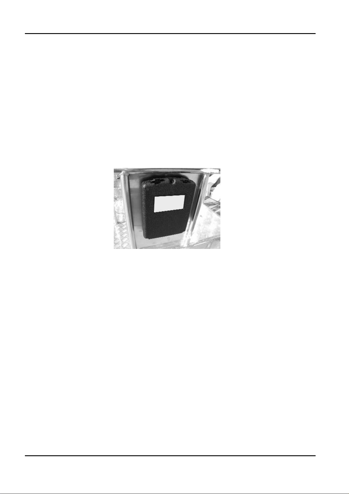
27 Use and maintenance manual compartment
28 Movement control remote control
29 Jib tie‑rod
30 Jib cylinder
31 Telescopic arm 2
32 Telescopic arm1
33 Third arm
34 Outrigger plate
35 Second ‑ third arm return
36 Basket levelling cylinder on connection
37 Third arm cylinder
38 Second arm
39 Second arm tie‑rod
40 Double pump with gears
41 Proportional valves compartment and hand pump
42 Electric components compartment
BOOM LIFT MODELS X23J
JLG
18
X23JR0620113

19
KEY
1 Tracked undercarriage
2 Emergency controls
3 Overhead part distributors
4 Battery charge
5 Coupling attachment + rotation motor
6 Swiveling turret
7 Base
8 Track part distributors compartment
9 Oil tank
10 Outrigger joint
11 Geared double pump
12 Battery pack + inverter + battery charger (
LITHIUM MOTOR)
13 Electric motor
14 Outrigger cylinder
15 Outrigger
16 First arm
17 First arm tie‑rod
18 First‑second arm cylinder
19 First‑second arm return
20 Jib arm
21 Jib return
22 Basket on basket levelling cylinder
23 Rotary actuator for basket rotation
24 Basket support
25 Basket access ladder
BOOM LIFT MODELS X23J
JLG
X23JR0620113
LITHIUM MOTOR

26 Basket
27 Use and maintenance manual compartment
28 Movement control remote control
29 Jib tie‑rod
30 Jib cylinder
31 Telescopic arm 2
32 Telescopic arm1
33 Third arm
34 Outrigger plate
35 Second ‑ third arm return
36 Basket levelling cylinder on connection
37 Third arm cylinder
38 Second arm
39 Second arm tie‑rod
40 Ignition key
41 Proportional valves compartment and hand pump
42 Electric components compartment + buffer battery
BOOM LIFT MODELS X23J
JLG
20
X23JR0620113

21
2.1.6 TRANSPORT AND STABILISATION POSITION (STANDARD VERSION)
The overhead platform has rotating outriggers on a joint connecting the frame and outrigger
itself.
Regarding the outriggers, two positions are defined:
• TRANSPORT POSITION
• STABILISATION POSITION
The transport position is defined as the completely closed configuration and aligned with the
completely lifted and turned outriggers in a way to be parallel to the machine axle.
This configuration is the most compact possible for the machine and is that recommended for
all traversing operations on flat surfaces.
In the transport configuration, the vicinity of the outrig‑
ger plates to the basket handrail creates a potential
shearing hazard, it is appropriately indicated with
stickers.
Do not place the hands in this area during traversing
phases.
The stabilisation position is defined as that with the
outriggers raised from the ground, but turned by
about 45° with respect to the machine axis in a way
to almost create a square with the outrigger plates
positioned on the ends.
A lock pin with spring positioning blocks the outrig‑
gers in one or other position.
For the stabilization positions of the version with variable stabilization area please read
paragraph 6.4.6 Passage from transport configuration to stabilisation configuration Stan‑
dard version.
BOOM LIFT MODELS X23J
JLG
X23JR0620113
IMPORTANT
IMPORTANTE

2.2 GENERAL SAFETY STANDARDS
The functioning of the MEWP must be in compliance with international standards of referen‑
ce (see paragraph “NORMATIVE REFERENCES” in the first pages of the manual) and natio‑
nal or regional standards if stricter.
The operator must read, understand and follow all the instructions and warnings, contained
in this manual and on the machine, regarding the safe use of the MEWP.
FAILURE TO COMPLY WITH THE SAFETY PRECAUTIONS LISTED IN THIS SECTION
AND STATED ON THE MACHINE CAN CAUSE INJURY OR DEATH OF THE STAFF AND
DAMAGE TO THE MACHINE AND CONSTITUTES A SERIOUS INFRACTION OF THE
SAFETY STANDARDS.
This section of the USE AND MAINTENANCE MANUAL describes those procedures or
dangerous situations that can cause damage/injury to objects/persons and what the operator
must do to prevent them.
• The operator must always act as a professional, complying with safety standards, paying
attention not to under‑estimate his responsibility to himself and all objects and persons that
surround him.
• Before starting work it is indispensable that the operator has been completely and
clearly trained regarding the use of the machine in standard and emergency conditions.
That he has examined, understood and taken in all that stated in this user manual. That he
is sure that the safety devices are in perfect working order, that the necessary checks on
the machine are performed and that he becomes familiar with the conditions of the
ground on which he must manoeuvre and stabilise.
• The presence of at least one specialised person is necessary on the ground during working.
This person must know how to use the machine and be aware of the content of the USE AND
MAINTENANCE MANUAL and can intervene if necessary.
• It is prohibited to make modifications to the machine that could jeopardise functioning and
safety, without previous written authorisation from The Constructor which is not liable for
any injury or damage caused by this behaviour.
Protection devices and garments
Do not wear loose clothing, rings, watches or anything else
that may become entangled in moving parts.
When using the machine or performing maintenance wear a
hard helmet, goggles and accident‑prevention shoes, gloves
and hearing protection after having checked their integrity
along with any other IPD that the safety manager deems
necessary according to the risk analysis he has performed.
BOOM LIFT MODELS X23J
JLG
22
X23JR0620113
ATTENZIONE
WARNING

23
ALWAYS WEAR TYPE‑APPROVED AND CERTIFIED THE SLINGING. WHEN WORKING AT A HEIGHT MAKE
SURE YOU ARE WEARING THE SAFETY BELTS CORRECTLY AND THEY HAVE BEEN APPROPRIATELY ATTA
‑
CHED TO THE RELEVANT ANCHORAGE POINTS ON THE BASKET.
T
HE USE OF THE SLINGINGS IS COMPULSORY IN CONNECTION WITH THE LOCAL REGULATINS OF
EVERY SINGLE
STAT E. IN THOSE STATES WHERE THE LAW DOES NOT REQUIRE THE USE OF HOLDING
SYSTEMS
, THE CHOICE IS OF THE EMPLOYER OR/AND USER
Safety valves and safety components of the electric system
It is prohibited to modify and/or tamper with the safety and control valves of the main
hydraulic system and the adjustments of the electric plant. The Constructor is not liable
for injury to persons and damage to objects or to the machine if the standard calibration
of any hydraulic and electric/electronic component is tampered with.
Fire prevention
Keep the area around the engine clean, removing fragments of
wood, paper and other inflammable products; clean any fuel
leaks as they can be a potential cause of fire.
Petrol is extremely inflammable and explosive in particular
conditions. Re‑fuel in a well‑aired place with the engine at a
standstill.
Do not smoke or make sparks in the re‑fuel area or fuel stora‑
ge area.
After having re‑fuelled, make sure the cap is closed securely.
Do not touch the exhaust when hot during machine functioning or immediately after the
engine is switched off.
Prevention of damage caused by washing the machine
Do not aim high pressure jets onto electric components when
washing the machine. Do not use chemical detergents or
petrol that could cause serious damage to plastic components
and the paintwork.
A
LWAYS REMEMBER TO REMOVE THE REMOTE CONTROL AND COR‑
RECTLY CLOSE THE REMOTE CONTROL CONNECTION SOCKETS AND
EQUIPMENT POSITIONED ON THE MACHINE
, BEFORE WASHING.
BOOM LIFT MODELS X23J
JLG
X23JR0620113
IMPORTANT
IMPORTANTE

• Cleaning the machine
Always park the machine as shown in the figure in point 2.1.6.
When washing the machine, the ignition block must be disengaged, the key removed and the
emergency stop button pressed.
• Washing the outside of the machine
Never use flammable liquids. Adopt the above safety measures to
prevent sparks due to short‑circuits.
If washing the track with water cleaners, carefully protect all the
important parts and above all the electrical components. Follow the
instructions provided by the manufacturer of the detergent.
Clean the machine using water‑soluble detergents.
The more the elevating platform is cleaned, the more it will need to be greased (see par.
Grease points).
Do not wet the electric motors and the other electrical components directly. Do not aim the
spray directly onto adhesive labels and rating plates.
• Cleaning the electrical system
Never clean the inverter or the electric motor with water, as this may
cause damage to the electrical system.
BOOM LIFT MODELS X23J
JLG
24
X23JR0620113
ATTENZIONE
ATTENZIONE
ATTENTION
ATTENTION
ATTENTION
ATTENTION
ATTENZIONE
ATTENZIONE

25
Only use dry detergents, in accordance with the manufacturer’s instructions. Never remove
covers, guards and the like.
‑ Clean the electrical system using a dry, non‑metallic brush and low pressure air.
• After cleaning
Dry the machine carefully before starting it again (for example using compressed air).
If, despite all the precautions, moisture has penetrated into the electric motor or other parts
of the electric system, these must be dried using compressed air to avoid the risk of short‑cir‑
cuits.
Prevention of damage caused by the working machine
When the machine is stabilised and work started, do not enter its radius of action.
Systematically manoeuvre the controls slowly and regularly, do not reverse movements
abruptly.
During work operations outside of the basket, ALWAYS remain at a MINIMUM DISTANCE
OF 1 METER from the machine.
BOOM LIFT MODELS X23J
JLG
X23JR0620113
IMPORTANTE
IMPORTANT
ATTENTION
ATTENZIONE

2.3 SAFETY WARNINGS
2.3.1 GENERALITIES
To prevent accidents, before starting work or carrying out any
maintenance, read, understand and follow all precautions and
warnings contained in this manual. The user / operator of the
machine must refuse all operating responsibility until this
manual has been read and he has learned to manoeuvre the
machine completely under the surveillance of a skilled and qua‑
lified operator.
Carefully read all safety messages in this manual along with the safety signs on your machi‑
ne.
Keep the safety signs in a good state and replace them if they are damaged.
Make sure that any new machine components have the correct safety signs.
2.3.2 NOISE AND VIBRATIONS
The JLG platforms with engine have been tested according to the parameters of the 2000/14
CE European Standard, having a guaranteed sound power level detected, stated in the
machines EC Declaration of Conformity.
During the use of machines for aerial operations this value is further reduced due to the
moving away of the basket from the main source of noise.
The values of the vibrations transmitted to the operator via the controls and directly from the
surface of the basket resulted less than the maximum accepted limits.
BOOM LIFT MODELS X23J
JLG
26
X23JR0620113
 Loading...