


JLG 500RTS Parts Manual

Illustrated Parts Manual
Models
400RTS
500RTS
P/N
3120697
September 30, 2013


REVISION LOG
June 1, 1993 - Original Issue Of Manual
January 1996 - Revised
December 1997 - Revised
November 11, 1999 - Updated Page 7-3, 7-5, 7-14 & 7-15
July 18, 2000 - Revised
July 11, 2003 - Revised (Manual edited to 0010488 Revision 36 - 400RTS)
(Manual edited to 0010458 Revision 59 - 500RTS)
February 4, 2004 - Revised (Manual edited to 0010458 Revision 62 - 500RTS)
June 14, 2004 - Revised (Manual edited to 0010458 Revision 63 - 500RTS)
June 30, 2007 - Revised (Manual edited to 0010458 Revision 69 - 500RTS)
March 1, 2011 - Revised
September 30, 2013 - Revised
3120697 400RTS 500RTS A

REVISION LOG
B 400RTS 500RTS 3120697

TABLE OF CONTENTS
FIGURE NO. TITLE PAGE NO.
SECTION 1 - FRAME . . . . . . . . . . . . . . . . . . . . . . . . . . . . . . . . . . . . . . . . . . . . . . . . . . . . . .1-1
1-1 FRAME, STEERING, AND AXLE INSTALLATIONS . . . . . . . . . . . . . . . . . . . . . . . . . . . . 1-2
1-2 LOCKOUT VALVE ASSEMBLY . . . . . . . . . . . . . . . . . . . . . . . . . . . . . . . . . . . . . . . . . . . 1-8
1-3 TIRE AND WHEEL DRIVE INSTALLATIONS . . . . . . . . . . . . . . . . . . . . . . . . . . . . . . . . . 1-10
1-4 DRIVE MOTOR ASSEMBLY. . . . . . . . . . . . . . . . . . . . . . . . . . . . . . . . . . . . . . . . . . . . . . 1-14
1-5 DRIVE BRAKE ASSEMBLY . . . . . . . . . . . . . . . . . . . . . . . . . . . . . . . . . . . . . . . . . . . . . . 1-16
1-6 DRIVE HUB ASSEMBLIES. . . . . . . . . . . . . . . . . . . . . . . . . . . . . . . . . . . . . . . . . . . . . . . 1-20
1-7 DRIVE HUB/BRAKE ASSEMBLIES . . . . . . . . . . . . . . . . . . . . . . . . . . . . . . . . . . . . . . . . 1-24
1-8 FRAME MOUNTED COMPONENTS INSTALLATION . . . . . . . . . . . . . . . . . . . . . . . . . . 1-30
1-9 FRAME MOUNTED OPTIONS INSTALLATION. . . . . . . . . . . . . . . . . . . . . . . . . . . . . . . 1-36
1-10 TOW PACKAGE INSTALLATION - BALL (OPTIONAL) . . . . . . . . . . . . . . . . . . . . . . . . . 1-40
1-11 TOW PACKAGE INSTALLATION - PINTLE HOOK (OPTIONAL). . . . . . . . . . . . . . . . . . 1-42
SECTION 2 - GROUND CONTROLS . . . . . . . . . . . . . . . . . . . . . . . . . . . . . . . . . . . . . . . . . .2-1
2-1 CONTROL VALVES AND TANKS INSTALLATION . . . . . . . . . . . . . . . . . . . . . . . . . . . . 2-2
2-2 CONTROL VALVE ASSEMBLY (PRIOR TO S/N 107516) . . . . . . . . . . . . . . . . . . . . . . . 2-10
2-3 CONTROL VALVE ASSEMBLY (S/N 107516 TO PRESENT) . . . . . . . . . . . . . . . . . . . . 2-14
2-4 ENGINE INSTALLATION - FORD VSG-411. . . . . . . . . . . . . . . . . . . . . . . . . . . . . . . . . . 2-16
2-5 DUAL FUEL COMPONENTS INSTALLATION - FORD VSG-411 ENGINE OPTION . . . 2-24
2-6 110 VOLT GENERATOR INSTALLATION (FORD VSG-411) (OPTIONAL) . . . . . . . . . . 2-28
2-7 ENGINE INSTALLATION - FORD LSG-423 . . . . . . . . . . . . . . . . . . . . . . . . . . . . . . . . . . 2-30
2-8 ENGINE INSTALLATION - FORD LRG-423 DIS/LRG-425. . . . . . . . . . . . . . . . . . . . . . . 2-36
2-9 DUAL FUEL COMPONENTS INSTALLATION - FORD LSG-423/LRG-423 DIS/
LRG-425 . . . . . . . . . . . . . . . . . . . . . . . . . . . . . . . . . . . . . . . . . . . . . . . . . . . . . . . . . . 2-44
2-10 GENERATOR INSTALLATION - FORD LSG-423/LRG-423/LRG-425 . . . . . . . . . . . . . . 2-48
2-11 ENGINE INSTALLATION - DEUTZ F3L1011 . . . . . . . . . . . . . . . . . . . . . . . . . . . . . . . . . 2-52
2-12 110 VOLT GENERATOR INSTALLATION - DEUTZ (OPTIONAL) . . . . . . . . . . . . . . . . . 2-60
2-13 PUMP ASSEMBLY - SUNSTRAND . . . . . . . . . . . . . . . . . . . . . . . . . . . . . . . . . . . . . . . . 2-64
2-14 PUMP ASSEMBLY - BARNES . . . . . . . . . . . . . . . . . . . . . . . . . . . . . . . . . . . . . . . . . . . . 2-68
2-15 GROUND CONTROL BOX INSTALLATION. . . . . . . . . . . . . . . . . . . . . . . . . . . . . . . . . . 2-70
2-16 HOODS AND BEACON LIGHT INSTALLATION . . . . . . . . . . . . . . . . . . . . . . . . . . . . . . 2-74
SECTION 3 - SCISSORS ARMS . . . . . . . . . . . . . . . . . . . . . . . . . . . . . . . . . . . . . . . . . . . . .3-1
3-1 SIZZORS ARMS INSTALLATION - 400RTS (PRIOR TO S/N 41058) . . . . . . . . . . . . . . 3-2
3-2 SIZZORS ARMS INSTALLATION - 400RTS (S/N 41058 TO PRESENT). . . . . . . . . . . . 3-6
3-3 SIZZORS ARMS INSTALLATION - 500RTS (PRIOR TO S/N 27997) . . . . . . . . . . . . . . 3-10
3-4 SIZZORS ARMS INSTALLATION - 500RTS (S/N 27997 TO PRESENT). . . . . . . . . . . . 3-14
SECTION 4 - PLATFORM. . . . . . . . . . . . . . . . . . . . . . . . . . . . . . . . . . . . . . . . . . . . . . . . . . .4-1
4-1 FIXED PLATFORM (STANDARD), HANDRAILS AND OPTIONAL COMPONENTS
INSTALLATION . . . . . . . . . . . . . . . . . . . . . . . . . . . . . . . . . . . . . . . . . . . . . . . . . . . . 4-2
4-2 PLATFORM EXTENSION INSTALLATION (OPTIONAL) . . . . . . . . . . . . . . . . . . . . . . . . 4-8
4-3 PLATFORM EXTENSION INSTALLATION - MEGADECK (OPTIONAL) . . . . . . . . . . . . 4-12
4-4 POWER DECK EXTENSION AND PLATFORM ASSEMBLY . . . . . . . . . . . . . . . . . . . . . 4-16
4-5 PLATFORM CONSOLE BOX ASSEMBLY . . . . . . . . . . . . . . . . . . . . . . . . . . . . . . . . . . . 4-20
4-6 DRIVE/LIFT CONTROLLER ASSEMBLY (PRIOR TO S/N 57701) . . . . . . . . . . . . . . . . . 4-26
4-7 DRIVE/LIFT CONTROLLER ASSEMBLY (S/N 57701 TO PRESENT) . . . . . . . . . . . . . . 4-28
3120697 400RTS 500RTS i

TABLE OF CONTENTS
FIGURE NO. TITLE PAGE NO.
SECTION 5 - CYLINDER . . . . . . . . . . . . . . . . . . . . . . . . . . . . . . . . . . . . . . . . . . . . . . . . . . .5-1
5-1 AXLE LOCKOUT CYLINDER ASSEMBLY (OSCILLATING CYLINDER) (OPTIONAL) . . 5-2
5-2 LEVELING JACK CYLINDER ASSEMBLY (HYDRAULIC JACK OPTION)
(PRIOR TO S/N 104832) . . . . . . . . . . . . . . . . . . . . . . . . . . . . . . . . . . . . . . . . . . . . . . 5-4
5-3 LEVELING JACK CYLINDER ASSEMBLY (HYDRAULIC JACK OPTION)
(S/N 104832 TO PRESENT) . . . . . . . . . . . . . . . . . . . . . . . . . . . . . . . . . . . . . . . . . . . 5-6
5-4 LIFT CYLINDER ASSEMBLIES. . . . . . . . . . . . . . . . . . . . . . . . . . . . . . . . . . . . . . . . . . . . 5-10
5-5 PLATFORM EXTENSION CYLINDER ASSEMBLY. . . . . . . . . . . . . . . . . . . . . . . . . . . . . 5-14
5-6 STEER CYLINDER ASSEMBLY (MACHINES BUILT PRIOR TO JUNE 1993) . . . . . . . . 5-16
5-7 STEER CYLINDER ASSEMBLY (MACHINES BUILT JUNE 1993 TO PRESENT) . . . . . 5-18
SECTION 6 - HYDRAULIC . . . . . . . . . . . . . . . . . . . . . . . . . . . . . . . . . . . . . . . . . . . . . . . . . .6-1
6-1 HYDRAULIC DIAGRAM - AUXILIARY POWER . . . . . . . . . . . . . . . . . . . . . . . . . . . . . . . . 6-2
6-2 HYDRAULIC DIAGRAM - OSCILLATING AXLE (OPTIONAL). . . . . . . . . . . . . . . . . . . . . 6-4
6-3 HYDRAULIC DIAGRAM - PLATFORM EXTENSION. . . . . . . . . . . . . . . . . . . . . . . . . . . . 6-6
6-4 HYDRAULIC DIAGRAM - STANDARD 2WD/2WS . . . . . . . . . . . . . . . . . . . . . . . . . . . . . 6-10
6-5 HYDRAULIC DIAGRAM - STANDARD 4WD/2WS . . . . . . . . . . . . . . . . . . . . . . . . . . . . . 6-16
6-6 HYDRAULIC DIAGRAM - STANDARD 4WD/4WS . . . . . . . . . . . . . . . . . . . . . . . . . . . . . 6-22
6-7 HYDRAULIC DIAGRAM - STANDARD 2WD/4WS . . . . . . . . . . . . . . . . . . . . . . . . . . . . . 6-28
6-8 HYDRAULIC DIAGRAM - TOW PACKAGE (OPTIONAL) . . . . . . . . . . . . . . . . . . . . . . . . 6-34
6-9 HYDRAULIC DIAGRAM LIST . . . . . . . . . . . . . . . . . . . . . . . . . . . . . . . . . . . . . . . . . . . . . 6-36
SECTION 7 - ELECTRICAL . . . . . . . . . . . . . . . . . . . . . . . . . . . . . . . . . . . . . . . . . . . . . . . . .7-1
7-1 ELECTRICAL DIAGRAM LIST. . . . . . . . . . . . . . . . . . . . . . . . . . . . . . . . . . . . . . . . . . . . . 7-2
7-2 WIRING DIAGRAM - 0610114 CIRCUIT CARD . . . . . . . . . . . . . . . . . . . . . . . . . . . . . . . 7-8
7-3 WIRING DIAGRAM - DUAL FUEL (FORD) . . . . . . . . . . . . . . . . . . . . . . . . . . . . . . . . . . . 7-9
7-4 WIRING DIAGRAM - 110 VOLT GENERATOR (FORD) . . . . . . . . . . . . . . . . . . . . . . . . . 7-10
7-5 WIRING DIAGRAM - 110 VOLT GENERATOR (DEUTZ) . . . . . . . . . . . . . . . . . . . . . . . . 7-11
7-6 WIRING DIAGRAM - STANDARD 500RTS (FORD LRG-425 GAS MACHINES) . . . . . . 7-12
7-7 WIRING DIAGRAM - STANDARD 500RTS (DEUTZ DIESEL MACHINES). . . . . . . . . . . 7-14
7-8 WIRING DIAGRAM - CSA SPEC 500RTS (FORD LRG-425 GAS MACHINES) . . . . . . . 7-16
7-9 WIRING DIAGRAM - CSA SPEC 500RTS (DEUTZ DIESEL MACHINES) . . . . . . . . . . . 7-18
SECTION 8 - DECALS . . . . . . . . . . . . . . . . . . . . . . . . . . . . . . . . . . . . . . . . . . . . . . . . . . . . . 8-1
8-1 DECALS INSTALLATION - COMMON . . . . . . . . . . . . . . . . . . . . . . . . . . . . . . . . . . . . . . 8-2
8-2 DECALS INSTALLATION - COUNTRY SPECS . . . . . . . . . . . . . . . . . . . . . . . . . . . . . . . 8-6
SECTION 9 - RECOMMENDED SERVICE PARTS STOCK . . . . . . . . . . . . . . . . . . . . . . . . . 9-1
SECTION 10 - SPECIAL OPTIONS . . . . . . . . . . . . . . . . . . . . . . . . . . . . . . . . . . . . . . . . . . .10-1
SECTION 11 - PART NUMBER INDEX . . . . . . . . . . . . . . . . . . . . . . . . . . . . . . . . . . . . . . . .11-1
ii 400RTS 500RTS 3120697

SECTION 1
FRAME
3120697 400RTS 500RTS 1-1
SECTION 1 FRAME
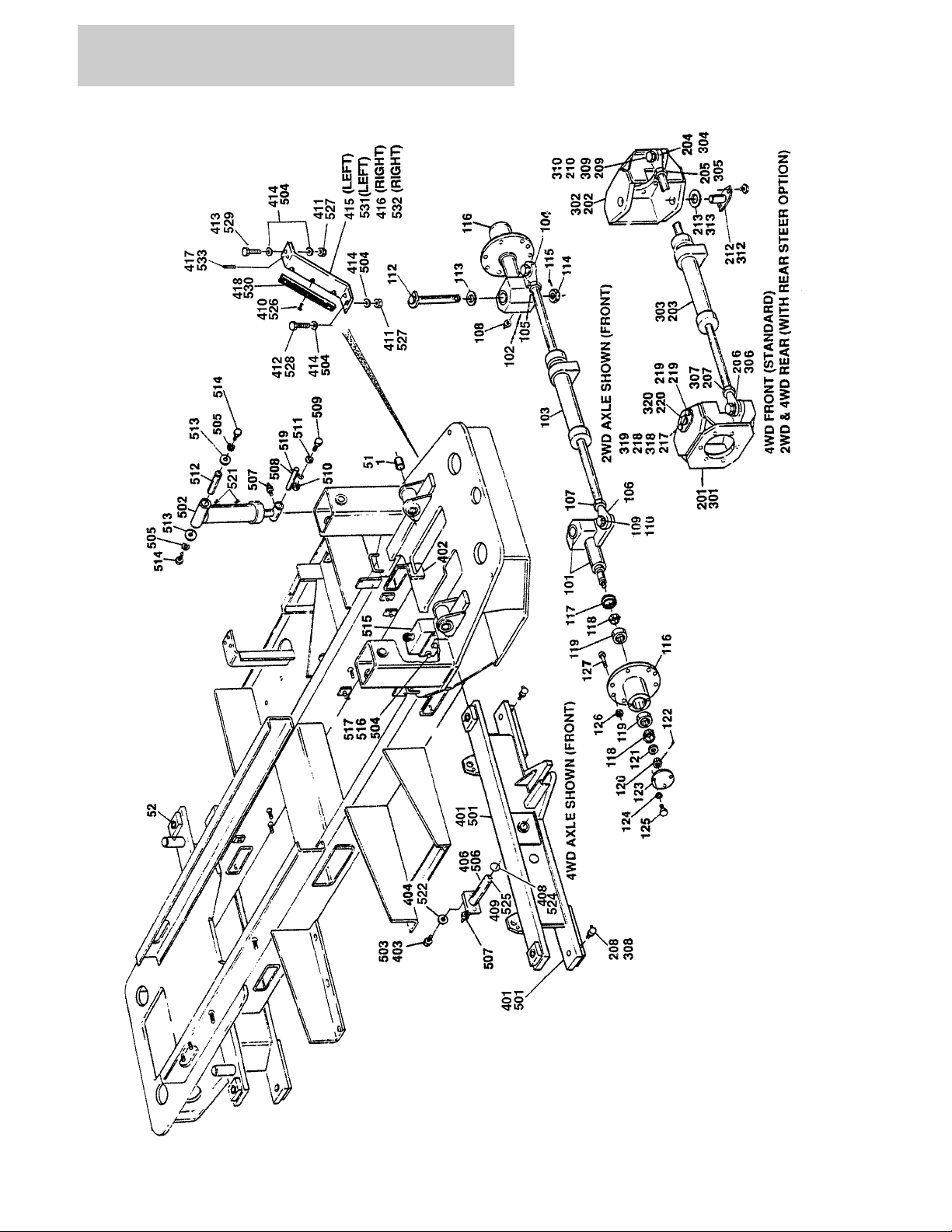
FIGURE 1-1. FRAME, STEERING, AND AXLE INSTALLATIONS
1-2 400RTS 500RTS 3120697

SECTION 1 FRAME
FIGURE 1-1. FRAME, STEERING, AND AXLE INSTALLATIONS
ITEM # PART NUMBER QTY. DESCRIPTION REV.
Ref. FRAME, STEERING AND AXLE INSTALLATIONS
Ref. FRAME WELDMENT - 2WS OPTIONS:
2360364 Ref. FRAME WELDMENT (PRIOR TO S/N 46528) 8
2360491 Ref. FRAME WELDMENT (S/N 46528 TO PRESENT) 2
1 0961739 2 Bushing, Bronze (Sizzor Arm Pivot)
Ref. FRAME WELDMENT - 4WS OPTIONS:
2360358 Ref. FRAME WELDMENT (PRIOR TO S/N 46528) 9
2360492 Ref. FRAME WELDMENT (S/N 46528 TO PRESENT) 2
51 0961739 2 Bushing, Bronze (Sizzor Arm Pivot)
52 0961029 4 Bushing, Bronze (Kingpin Pivot)
0252790 Ref. STEERING INSTALLATION - 2WD FRONT 3
0254214/0254215
Ref. STEERING INSTALLATION - 2WD FRONT (CSA) 7/2
101 1 Spindle Weldment (R.H.) Options:
4130287 Spindle Weldment (R.H.) (Standard)
4130306 Spindle Weldment (R.H.) (CSA)
0960523 2 Bushing, Bronze (Kingpin)
102 1 Spindle Weldment (L.H.) Options:
4130288 Spindle Weldment (Standard)
4130307 1 Spindle, Weldment (CSA)
0960523 2 Bushing, Bronze (Kingpin)
103 1 Steer Cylinder Assembly (See Section 5 for Breakdown)
Options:
1682681 Standard (Prior to June 1993)
1682967 Standard (June 1993 to Present)
1682967 CSA
104 1660204 1 Rod-End (Left Side)
105 3322602 1 Nut, Jam 1" - 12NF Right Hand Threads (Left Side)
106 1660205 1 Rod-End (Right Side)
107 3300228 1 Nut, Jam 1"-12" NF Left Hand Threads (Right Side)
108 2160002 2 Fitting, Grease
109 0642622 2 Bolt 1" - 8NC x 2 3/4"
110 4712600 A/R Flatwasher 1" Narrow
111 Not Used
112 3421243 2 Kingpin
113 0440183 2 Bearing, Thrust
114 3323403 2 Nut, Slotted 1 1/2"-12NF
115 3451012 2 Pin, Cotter 5/16" x 3"
116 2780177 2 Hub, Wheel
117 3960353 2 Seal, Oil
118 0440174 4 Cup, Bearing
119 0440175 4 Cone, Bearing
120 3322603 2 Nut, Slotted 1" -12NF
121 4740034 2 Washer, Hardened
3120697 400RTS 500RTS 1-3

SECTION 1 FRAME
FIGURE 1-1. FRAME, STEERING, AND AXLE INSTALLATIONS (CONTINUED)
ITEM # PART NUMBER QTY. DESCRIPTION REV.
122 3450610 2 Pin, Cotter 3/16" x 2 1/2"
123 1120311 2 Cap, Hub
124 0721004 6 Screw, Machine #10-24NC x 1/2"
125 4761000 6 Lockwasher #10
126 3300012 18 Nut, Wheel
127 0630137 18 Stud, Wheel
_ _ _ _ _ _ _ _ _ _ _ _ _ _ _ _ _ _
0100019 A/R Loctite
0100011 A/R Loctite #242
0253078 Ref. STEERING INSTALLATION - 4WD FRONT (STANDARD
PARTS WITH 2WS)
0253059 Ref. STEERING INSTALLATION - 2WD REAR (STANDARD PARTS
WHEN EQUIPPED WITH OPTIONAL
REAR STEER)
0254214 Ref. STEERING INSTALLATION - 2WD REAR (STANDARD PARTS
WHEN EQUIPPED WITH OPTIONAL
REAR STEER) (CSA)
201 4130279 1 Spindle Weldment (Right Side - Front/Left Side - Rear)
202 4130280 1 Spindle Weldment (Left Side - Front/Right Side - Rear)
203 1 Steer Cylinder Assembly (See Section 5 for Breakdown)
Options:
Use 1682967 Standard (Prior to June 1993) (was p/n 1682681)
1682967 Standard (June 1993 to Present)
1682967 CSA
204 1660204 1 Rod-End
205 3322602 1 Nut, Jam 1"-12NF
206 1660205 1 Rod-End
207 3300228 1 Nut, Jam 1"-12NF Left Hand Thread
208 2160003 4 Fitting, Grease - 45°
209 0642622 2 Bolt 1"-8NC x 2 3/4"
210 4712600 A/R Flatwasher 1" Narrow
211 Not Used
212 3421190 4 Kingpin
213 0440161 4 Bearing, Thrust
214 to 216 Not Used
217 0641608 8 Bolt 3/8"-16NC x 1"
218 4751600 8 Flatwasher 3/8"
219 1380124 8 Clip, Retainer (Prior to S/N 69836)
220 4920096
0100019 A/R Loctite
0100011 A/R Loctite #242
4 ft./1.2m
Wire, Safety (4 Pieces 1 ft./30 cm Long) (Prior to S/N 69836)
— — — — — — — — — —
6
9
7
0252532 Ref. STEERING INSTALLATION - 4WD FRONT AND REAR (STAN-
DARD PARTS WHEN EQUIPPED WITH OPTIONAL REAR
STEER)
301 4130279 1 Spindle Weldment (Right Side - Front/Left Side-Rear)
302 4130280 2 Spindle Weldment (Left Side - Front/Right Side - Rear)
8
1-4 400RTS 500RTS 3120697

SECTION 1 FRAME
FIGURE 1-1. FRAME, STEERING, AND AXLE INSTALLATIONS (CONTINUED)
ITEM # PART NUMBER QTY. DESCRIPTION REV.
303 2 Steer Cylinder Assembly (See Section 5 for Breakdown)
Options:
1682681 Prior to June 1993
1682967 June 1993 to Present
304 1660204 2 Rod-End
305 3322602 2 Nut, Jam 1"-12NF
306 1660205 2 Rod-End
307 3300228 2 Nut, Jam 1"-12NF Left Hand Thread
308 2160003 8 Fitting, Grease - 45°
309 0642622 4 Bolt 1"-8NC x 2 3/4"
310 4712600 A/R Flatwasher 1" Narrow
311 Not Used
312 3421190 8 Kingpin
313 0440161 8 Bearing, Thrust
314 Not Used
315 Not Used
316 Not Used
317 0641608 16 Bolt 3/8"-16NC x 1"
318 4751600 16 Flatwasher 3/8"
319 1380124 16 Clip, Retainer (Prior to S/N 69836)
320 4920096
0100019 A/R Loctite
8 ft./2.4m
Wire, Safety (8 Pieces 1 ft./30cm long) (Prior to S/N 69836)
— — — — — — — — — —
Ref. FIXED AXLE INSTALLATIONS (STANDARD PARTS)
0253171 Ref. FIXED AXLE INSTALLATION - 2WD 4
0253172 Ref. FIXED AXLE INSTALLATION - 4WD 4
401 1 Axle Weldment - 2WD Options:
4844129 Prior to October 1994
4844868 October 1994 to Present
0961029 4 Bushing, Bronze (Kingpin Pivot)
1 Axle Weldment - 4WD Options:
4844059 Prior to October 1994
4844867 October 1994 to Present
0961029 4 Bushing, Bronze (Kingpin Pivot)
402 0560901 2 Block, Stop
403 0641610 1 Bolt 3/8"-16NC x 1 1/4"
404 4740185 2 Flatwasher
405 Not Used
406 1 Pin Weldment Options:
4842621 Prior to October 1994
3422401 October 1994 to Present
407 Not Used
408 3780183 2 O-Ring (October 1994 to Present)
409 4640812 1 Valve, Relief (October 1994 to Present)
410 3820030 6 Rivet, Pop 3/16" (Prior to S/N 77909)
411 3311605 8 Nut 3/8"-16NC (September 1995 to Present)
412 0641612 4 Bolt 3/8" x 1 1/2"-16NC (September 1995 to Present)
413 0641614 4 Bolt 3/8" x 1 3/4"-16NC (September 1995 to Present)
3120697 400RTS 500RTS 1-5

SECTION 1 FRAME
FIGURE 1-1. FRAME, STEERING, AND AXLE INSTALLATIONS (CONTINUED)
ITEM # PART NUMBER QTY. DESCRIPTION REV.
414 4751600 16 Flatwasher (September 1995 to Present)
415 0902214 1 Bracket, L.H. (September 1995 to Present)
416 0902215 1 Bracket, R.H. (September 1995 to Present)
417 3440616 4 Pin, Roll 3/16" x 1" (September 1995 to Present)
418 4280298 2 Strip, Wear (Prior to S/N 77909)
Ref. OSCILLATING AXLE INSTALLATION - OPTION (STANDARD
PARTS WHEN EQUIPPED)
0252772 Ref. OSCILLATING AXLE INSTALLATION - 2WD 11
0252525 Ref. OSCILLATING AXLE INSTALLATION - 4WD 12
501 1 Axle Weldment - 2WDOptions:
4844129 Prior to October 1994
4844868 October 1994 to Present
0961029 4 Bushing, Bronze (Prior to October 1994)
1 Axle Weldment - 4WD Options:
4844059 Prior to October 1994
4844867 October 1994 to Present
0961029 4 Bushing, Bronze (Prior to October 1994)
502 1682185 2 Axle Lockout Cylinder Assembly (See Section 5 for Break-
down)
503 0641608 2 Bolt 3/8"-16NC x 1"
504 4751600 18 Flatwasher 3/8"
505 4761600 4 Lockwasher 3/8"
506 1 Pin, Axle Pivot Options:
4842621 Prior to October 1994
3422401 October 1994 to Present
507 2160002 3 Fitting, Grease
508 3422137 2 Pin, Attach (Bottom)
509 0641510 2 Bolt 5/16"-18NC x 1 1/4"
510 3311505 2 Locknut 5/16"-18NC
511 4751500 2 Flatwasher 5/16"
512 3421335 2 Pin, Attach (Top)
513 4740308 4 Flatwasher, Special
514 0641608 4 Bolt 3/8-16NC x 1"
515 4640485 1 Lockout Valve Assembly (See Figure 1-2 for Breakdown)
516 0641632 2 Bolt 3/8"-16NC x 4"
517 3311605 2 Nut 3/8"-16NC
518 Not Used
519 3841143 2 Pin, Keeper
520 Not Used
521 4640273 6 Bleeder (October 1994 to Present)
522 4740185 2 Washer (October 1994 to Present)
523 Not Used
524 3780183 2 O-Ring (October 1994 to Present)
525 4640812 1 Valve, Relief (October 1994 to Present)
526 3820030 6 Rivet, Pop 3/16" (Prior to S/N 77909)
527 3311605 8 Nut 3/8"-16NC (September 1995 to Present)
528 0641612 4 Bolt 3/8" - 16NC x 1 1/2" (September 1995 to Present)
529 0641614 4 Bolt 3/8"- 16NC x 1 3/4" (September 1995 to Present)
1-6 400RTS 500RTS 3120697

SECTION 1 FRAME
FIGURE 1-1. FRAME, STEERING, AND AXLE INSTALLATIONS (CONTINUED)
ITEM # PART NUMBER QTY. DESCRIPTION REV.
530 4280298 2 Strip, Wear (Prior to S/N 77909)
531 0902214 1 Bracket, L.H. (September 1995 to Present)
532 0902215 1 Bracket, R.H. (September 1995 to Present)
533 3440616 4 Pin, Roll (September 1995 to Present)
— — — — — — — — — —
0100019 A/R Loctite
3120697 400RTS 500RTS 1-7
SECTION 1 FRAME
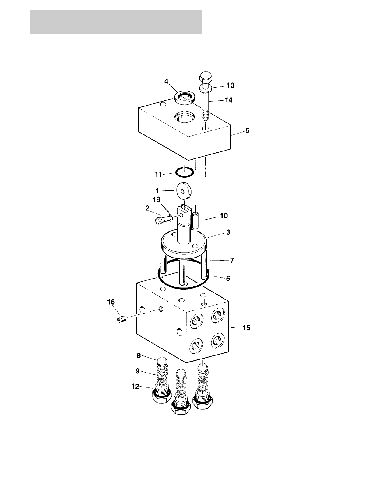
FIGURE 1-2. LOCKOUT VALVE ASSEMBLY
1-8 400RTS 500RTS 3120697

SECTION 1 FRAME
FIGURE 1-2. LOCKOUT VALVE ASSEMBLY
ITEM # PART NUMBER QTY. DESCRIPTION REV.
4640485 Ref. LOCKOUT VALVE ASSEMBLY B
1 3860037 1 Roller, Cam
2 3430407 1 Pin, Clevis 1/4" x 1"
3 3840833 1 Rod, Plunger
4 3960047 1 Seal, Rod
5 0560679 1 Block, Valve Top
6 3790231 1 O-Ring
7 3840854 4 Rod
8 0320008 4 Ball, Valve
9 4160078 4 Spring
10 3421284 2 Pin
11 3790116 1 O-Ring
12 2180658 4 Plug, Modified
13 0641518 2 Bolt 5/16"-18NC x 2 1/4"
14 4761500 2 Lockwasher 5/16"
15 0560467 1 Block, Valve
16 2200222 1 Plug 1/4" NPT
17 Not Used
18 3450203 1 Pin, Cotter
— — — — — — — — — —
0100011 A/R Loctite
3120697 400RTS 500RTS 1-9
SECTION 1 FRAME
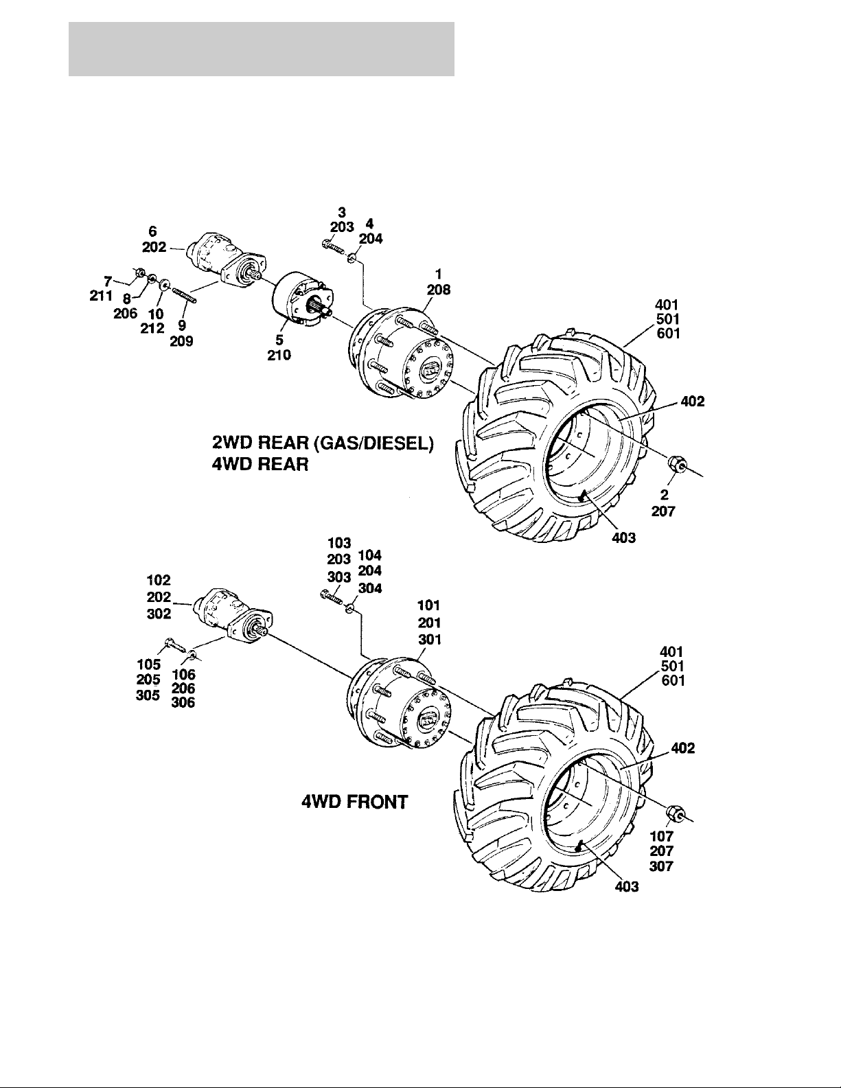
FIGURE 1-3. TIRE AND WHEEL DRIVE INSTALLATIONS
1-10 400RTS 500RTS 3120697

SECTION 1 FRAME
FIGURE 1-3. TIRE AND WHEEL DRIVE INSTALLATIONS
ITEM # PART NUMBER QTY. DESCRIPTION REV.
Ref. TIRE AND WHEEL DRIVE INSTALLATIONS
0252484 Ref. WHEEL DRIVE INSTALLATION - 2WD/2WS 3
1 2780169 2 Drive Hub Assembly (See Figure 1-6 for Breakdown)
2 3300012 18 Nut, Wheel
3 0642014 12 Bolt 5/8"-11NC x 1 3/4"
4 4762000 12 Lockwasher 5/8"
5 0920084 2 Drive Brake Assembly (See Figure 1-5 for Breakdown) (Prior to
S/N 36645)
0920110 2 Drive Brake Assembly (See Figure 1-5 for Breakdown) (S/N
36645 to Present)
6 3160158 2 Drive Motor Assembly (See Figure 1-4 for Breakdown)
7 3311801 4 Nut 1/2"-13NC
8 4761800 4 Lockwasher 1/2"
9 4300092 4 Stud 1/2"-13NC x 5 1/2"
10 4711800 4 Flatwasher 1/2" Narrow
— — — — — — — — — — —
0100011 A/R Loctite #242
0251661 Ref. WHEEL DRIVE INSTALLATION - 2WD/4WS B
101 2780195 2 Drive Hub/Brake Assembly (See Figure 1-7 for Breakdown)
102 3160158 2 Drive Motor Assembly (See Figure 1-4 for Breakdown)
103 0642014 12 Bolt 5/8"-11NC x 1 3/4"
104 4762000 12 Lockwasher 5/8"
105 0641810 4 Bolt 1/2"-13NC x 1 1/4"
106 4761800 4 Lockwasher 1/2"
107 3300012 18 Nut, Wheel
0253545 Ref. WHEEL DRIVE INSTALLATION - 4WD/2WS FRONT AND
REAR (2MPH)
0255103 Ref. WHEEL DRIVE INSTALLATION - 4WD/2WS FRONT
AND REAR (4MPH)
201 2 Drive Hub/Brake Assembly (See Figure 1-7 for Breakdown)
Options:
2780191 2 MPH
2780193 4 MPH
202 3160158 4 Drive Motor Assembly (See Figure 1-4 for Breakdown)
203 0642014 24 Bolt 5/8"-11NC x 1 7/8"
204 4762000 24 Lockwasher 5/8"
205 0641810 4 Bolt 1/2"-13NC x 1 1/4"
206 4761800 8 Lockwasher 1/2"
207 3300012 36 Nut, Wheel
208 2 Drive Hub Assembly (See Figure 1-6 for Breakdown) Options:
2780167 2 MPH
2780175 4 MPH
209 4300092 4 Stud 1/2"-13NC x 5 1/2"
2
2
3120697 400RTS 500RTS 1-11

SECTION 1 FRAME
FIGURE 1-3. TIRE AND WHEEL DRIVE INSTALLATIONS (CONTINUED)
ITEM # PART NUMBER QTY. DESCRIPTION REV.
210 0920084 2 Drive Brake Assembly (See Figure 1-5 for Breakdown) (Prior to
S/N 36645)
0920110 2 Drive Brake Assembly (See Figure 1-5 for Breakdown)
(S/N 36645 to Present)
211 3311801 4 Nut 1/2"-13NC
212 4711800 4 Flatwasher 1/2"
— — — — — — — — — —
0100011 A/R Loctite #242
0251660 Ref. WHEEL DRIVE INSTALLATION - 4WD/4WS FRONT
FRONT AND REAR (2MPH)
301 2780191 4 Drive Hub/Brake Assembly (See Figure 1-7 for Breakdown)
302 3160158 4 Drive Motor Assembly (See Figure 1-4 for Breakdown)
303 0642014 24 Bolt 5/8" - 11NC x 1 3/4"
304 4762000 24 Lockwasher 5/8"
305 0641810 8 Bolt 1/2"-13NC x 1 1/4"
306 4761800 8 Lockwasher 1/2"
307 3300012 36 Nut, Wheel
Ref. TIRE AND WHEEL INSTALLATIONS:
Ref. STANDARD 31-15.5 x 15 —
0250888 Ref. PRIOR TO S/N 115825 —
0273457 Ref. S/N 115825 TO PRESENT A
Ref. OPTIONAL 12 x 16.5 LOADER LUG Options:
0251261 Ref. PRIOR TO S/N 44590 —
0258395 Ref. S/N 44590 TO PRESENT 1
0259697 Ref. OPTIONAL 31 x 13.5 x 15 STRAIGHT RIB (S/N 67581 TO
PRESENT)
Ref. Note: Assemblies may require ballast/foam filling to manu-
facturer’s specifications prior to installing on a machine.
Refer to Operation & Safety or Service & Maintenance Manuals. Purchase individual tire and/or rim only if able to foam
fill tire & wheel assembly, otherwise, purchase complete
assembly.
Tire and Wheel Assembly - Left Side Options:
2 Standard 31-16.5 x 15 Options:
0250886 Prior to S/N 115825 B
0273412 S/N 115825 to Present A
Optional 12 x 16.5 Loaded Lug Options:
0251260 2 Prior to S/N 44590 —
0258393 2 S/N 44590 to Present 1
0259695 2 Optional 31 x 13.5 x 15 Straight Rib
Tire and Wheel Assembly - Right Side Options:
2 Standard 31-16.5 x 15 Options:
Use 0273413 Prior to S/N 115825 (was p/n 0250887) B
0273413 S/N 115825 to Present A
Optional 12 x 16.5 Loaded Lug Options:
0251259 2 Prior to S/N 44590 —
0258394 2 S/N 44590 to Present 1
0259695 2 Optional 31 x 13.5 x 15 Straight Rib
B
1
1-12 400RTS 500RTS 3120697

SECTION 1 FRAME
FIGURE 1-3. TIRE AND WHEEL DRIVE INSTALLATIONS (CONTINUED)
ITEM # PART NUMBER QTY. DESCRIPTION REV.
401 4 Tire Options:
Use 4520267 Standard 31-16.5 x 15 - OTR TRITAN (was p/n 4520123)
4520267 Standard 31-16.5 x 15 - OTR NHS
4520129 Optional 12 x 16.5 Loaded Lug
4520225 Optional 31 x 13.5 x 15 Straight Rib
402 4 Wheel Options:
4843635 Wheel - 15 x 13
4860126 Wheel - 16.5 x 9.75
4860065 4 Wheel - 15 x 10
403 4 Stem, Valve Options:
4640392 Standard 31-16.5 x 15
4640113 Optional 12 x 16.5 Loaded Lug
4640392 Optional 31 x 13.5 x 15 Straight Rib
404 1702738 4 Decal - 45 PSI (Not Shown) (Optional 31 x 13.5 x 15 Straight
Rib Only)
Ref. TIRE AND WHEEL INSTALLATIONS
0253089 Ref. OPTIONAL FOAM FILLED 12 x 16.5 —
Ref. TIRE AND WHEEL INSTALLATION - OPTIONAL FOAM
FILLED OPTIONS:
0255660 Ref. FOAM FILLED 31 x 15.50 x 15 - OTR TRITAN (Prior to
S/N 115825)
0272826 Ref. FOAM FILLED 31 x 15.50 x 15 - OTR NHS (S/N 115825 to
Present)
Ref. Note: Assemblies may require ballast/foam filling to
manufacturer’s specifications prior to installing on a
machine. Refer to Operation & Safety or Service &
Maintenance Manuals. Purchase individual tire and/or rim
only if able to foam fill tire & wheel assembly, otherwise,
purchase complete assembly.
—
—
A
501 2 Tire and Wheel Assembly - Left Side Options: —
0253088 12 x 16.5
Use 0273414 31 x 15.50 x 15 - OTR Tritan (was p/n 0255661)
0273414 31 x 15.50 x 15 - OTR NHS
2 Tire and Wheel Assembly - Right Side Options: —
0253087 12 x 16.5
Use 0273415 31 x 15.50 x 15 - OTR Tritan (was p/n 0255662)
0273415 31 x 15.50 x 15 - OTR NHS
Ref TIRE AND WHEEL INSTALLATION - OPTIONAL NON-MARK-
ING TIRES
601 4520153 4 Tire and Wheel Assembly - Non Marking A
3120697 400RTS 500RTS 1-13
SECTION 1 FRAME
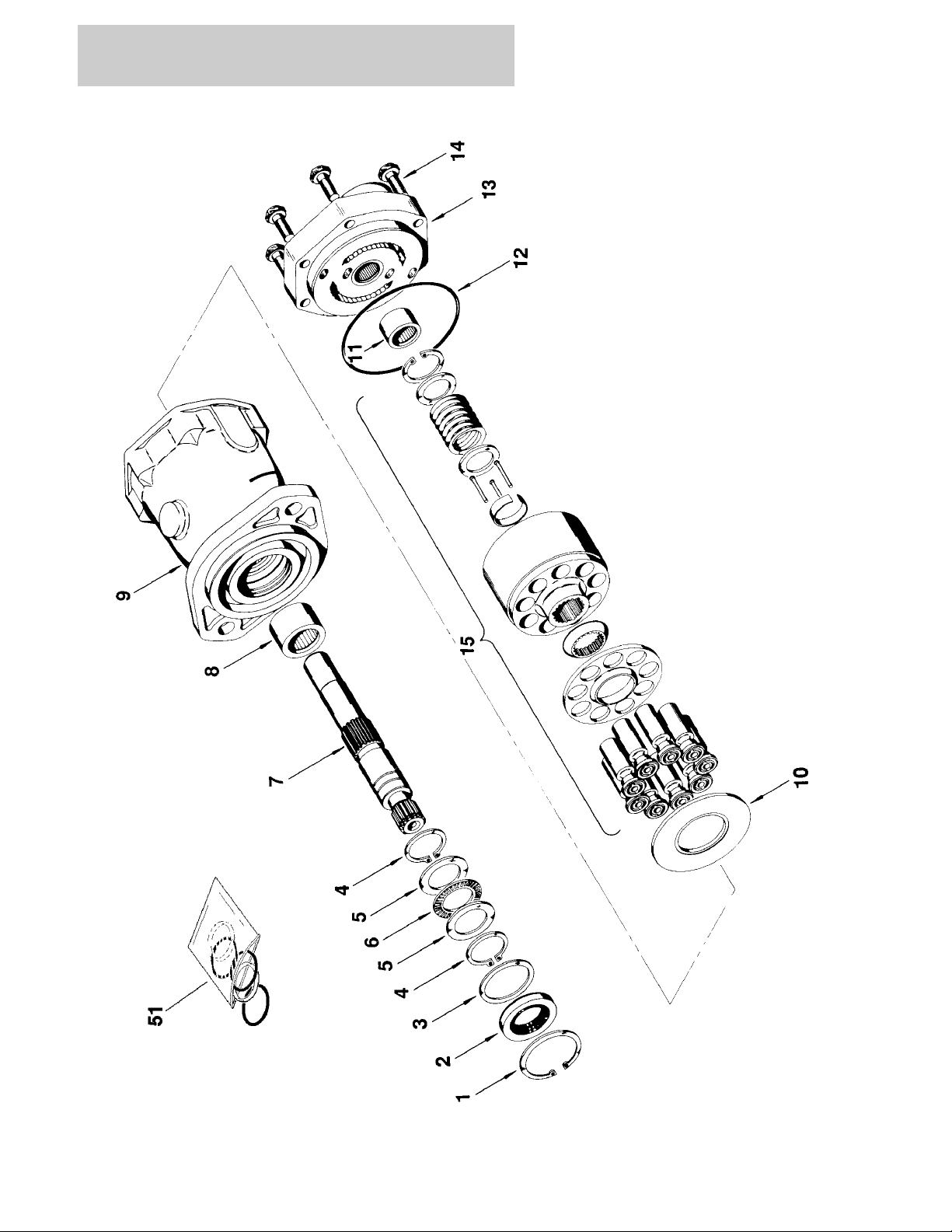
FIGURE 1-4. DRIVE MOTOR ASSEMBLY
1-14 400RTS 500RTS 3120697

SECTION 1 FRAME
FIGURE 1-4. DRIVE MOTOR ASSEMBLY
ITEM # PART NUMBER QTY. DESCRIPTION REV.
Ref. DRIVE MOTOR ASSEMBLY
3160158 Ref. DRIVE MOTOR ASSEMBLY (STANDARD PARTS)
1 Use Item 51 1 Ring, Retaining
2 Use Item 51 1 Seal, Shaft
3 7004906 1 Washer
4 Use Item 51 2 Ring, Retaining
5 7004907 2 Race, Thrust
6 7004908 1 Bearing, Thrust
7 7007874 1 Shaft, Splined
8 7004910 1 Bearing
9 7007875 1 Housing Assembly (Includes Item 8)
10 7007876 1 Insert, Camplate
11 7004917 1 Bearing
12 Use Item 51 1 O-Ring
13 7007878 1 Back Plate Assembly (Includes Item 11)
14 7007879 6 Bolt
15 7007880 1 Rotating Kit Assembly (Sold As An Assembly Only)
— — — — — — — — — —
51 2900714 1 Seal Kit (Includes Items 1,2,4 and 12)
3120697 400RTS 500RTS 1-15
SECTION 1 FRAME
FIGURE 1-5. DRIVE BRAKE ASSEMBLY
1-16 400RTS 500RTS 3120697

SECTION 1 FRAME
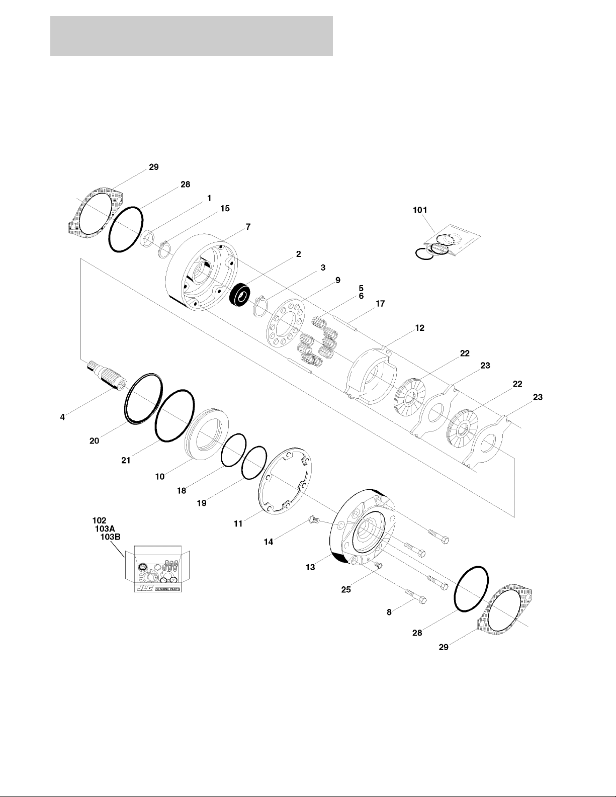
FIGURE 1-5. DRIVE BRAKE ASSEMBLY
ITEM # PART NUMBER QTY. DESCRIPTION REV.
Ref. DRIVE BRAKE ASSEMBLIES
0920084 Ref. MICO - (ORIGINAL EQUIPMENT) (MACHINES BUILT PRIOR
TO S/N 36645)
0920110 Ref. MICO - (SERVICE REPLACEMENT) (MACHINES BUILT S/N
36645 TO PRESENT)
Ref. Note: Original Equipment Brake may have been replaced with
Service Replacement Brake. Identify the brake by the serial
number plate before ordering parts.
1 See Note 1 Seal, Oil (Note: Use Item 101 & 102)
2 Use Item 102 1 Bearing
3 7007977 1 Ring, Retaining
4 7011712 1 Shaft
5 6 Spring Options:
7007979 Spring (Inner) - Prior to S/N 36645 (Use with p/n 0920084)
7007970 Spring (Red) - S/N 36645 to Present (Use with p/n 0920110)
6 A/R Spring Options:
7007980 6 Spring (Outer) - Prior to S/N 36645 (Use with p/n 0920084)
7018602 3 Spring (Blue) - S/N 36645 to Present (Use with p/n 0920110)
7 1 Housing Options:
7011713 Prior to S/N 36645 (Use with p/n 0920084)
7018605 S/N 36645 to Present (Use with p/n 0920110)
8 4 Bolt, Washer Head Options:
7007985 Prior to S/N 36645 (Use with p/n 0920084)
7018607 S/N 36645 to Present (Use with p/n 0920110)
9 1 Guide, Spring Options:
7011717 Prior to S/N 36645 (Use with p/n 0920084)
7018606 S/N 36645 to Present (Use with p/n 0920110)
10 1 Piston Options:
7007923 Prior to S/N 36645 (Use with p/n 0920084)
7018603 S/N 36645 to Present (Use with p/n 0920110)
11 See Note 1 Seal, Case (Note: Use Item 101,102, 103A & 103B)
12 Use Item 103B 1 Plate, Return
7011715 2 Separator Assembly
7011714 4 Pin
7007983 2 Separator
13 7007986 1 Cover
14 7007914 1 Screw, Bleeder
15 7011716 1 Ring, Retainer
16 Not Used
17 7007987 2 Pin, Dowel
18 Use Item 101 1 Ring, Back-up
19 Use Item 101 1 O-Ring
20 Use Item 101 1 Ring, Back-up
21 Use Item 101 1 O-Ring
22 See Note 2 Rotor (Note: Use Item 103A & 103B)
23 See Note 2 Stator (Note: Use Item 103A & 103B)
24 Not Used
25 7007924 1 Plug, Pipe
26 Not Used
—
2
3120697 400RTS 500RTS 1-17

SECTION 1 FRAME
FIGURE 1-5. DRIVE BRAKE ASSEMBLY (CONTINUED)
ITEM # PART NUMBER QTY. DESCRIPTION REV.
27 Not Used
28 See Note 2 O-Ring (Note: Use Item 101,102, 103A & 103B)
29 7007933 2 Gasket
— — — — — — — — — —
101 2900766 1 Seal Kit (Includes Items 1,11,18,19,20,21,28 and 29)
102 2900768 1 Bearing Kit (Includes Items 1,2,11,28 and 29)
103 1 Lining Kit Options:
103A 2900767 Lining Kit (Includes Items 58, 11, 22,23, 28 and 29) (Prior to
S/N 36645 (Use with p/n 0920084)
103B 7018608 Lining Kit (Includes Items 58, 11, 22,23, 28 and 29) (S/N
36645 to Present (Use with p/n 0920110)
1-18 400RTS 500RTS 3120697

SECTION 1 FRAME
FIGURE 1-5. DRIVE BRAKE ASSEMBLY (CONTINUED)
ITEM # PART NUMBER QTY. DESCRIPTION REV.
3120697 400RTS 500RTS 1-19
SECTION 1 FRAME
FIGURE 1-6. DRIVE HUB ASSEMBLIES
1-20 400RTS 500RTS 3120697

SECTION 1 FRAME
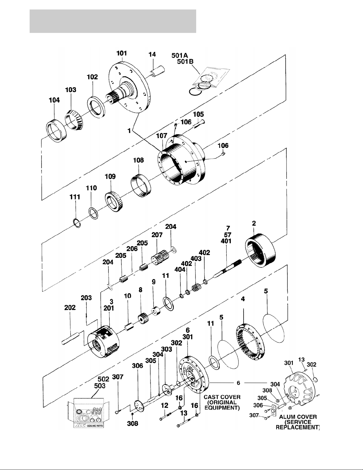
FIGURE 1-6. DRIVE HUB ASSEMBLIES
ITEM # PART NUMBER QTY. DESCRIPTION REV.
Ref. DRIVE HUB ASSEMBLIES
2780169 Ref. DRIVE HUB ASSEMBLY -2WD/2WS GAS/DIESEL
(2MPH)
2780167 Ref. DRIVE HUB ASSEMBLY - 4WD/2WS REAR DRIVE
ONLY (2MPH)
2780175 Ref. DRIVE HUB ASSEMBLY - 4WD/2WS REAR DRIVE
ONLY (4MPH)
1 1 Hub-Spindle Sub Assembly (See Items 101-111 for Breakdown)
2 7000246 1 Gear, Internal
3 7000247 1 Carrier Assembly (See Items 201-207 for Breakdown)
4 7000248 1 Gear, Ring
5 7000230 2 O-Ring
6 7001989 1 Cover Assembly (Includes Items 301-308)
7 1 Input Shaft Assembly (See Items 401-404 for Breakdown)
Options:
7000250 Input Shaft Assembly (2WD Machines)
7007650 Input Shaft Assembly (4WD Machines)
8 1 Gear, Input Options:
7000251 Gear, Input (2WD)
7007652 Gear, Input (4WD)
9 1 Spacer, Thrust Options:
7000252 Spacer, Thrust (2WD Machines)
7007653 Spacer, Thrust (4WD Machines)
10 1 Spacer, Thrust Options:
Not Required Spacer, Thrust (2WD Machines)
7007654 Spacer, Thrust (4WD Machines)
11 7000253 2 Washer, Thrust
12 7000217 12 Bolt
13 7000214 4 Bolt, Shoulder
14 7000206 1 Coupling
15 Not Used
16 7007603 16 Flatwasher
B
B
B
Ref. HUB - SPINDLE SUB-ASSEMBLY
101 7001997 1 Spindle
102 7001998 1 Seal
103 Use Item 502 1 Cone, Bearing
104 Use Item 502 1 Cup, Bearing
105 7007697 9 Bolt, Wheel
106 7000242 2 Plug, Pipe
107 7007601 1 Hub
108 7000257 1 Cup, Bearing
109 7000258 1 Cone, Bearing
110 7000232 1 Spacer
111 7000229 1 Ring, Retaining
3120697 400RTS 500RTS 1-21

SECTION 1 FRAME
FIGURE 1-6. DRIVE HUB ASSEMBLIES (CONTINUED)
ITEM # PART NUMBER QTY. DESCRIPTION REV.
7000247 Ref. CARRIER ASSEMBLY
201 7001931 1 Carrier
202 7001911 3 Shaft
203 7001913 3 Pin, Roll
204 7001985 6 Washer, Thrust
205 7001909 96 Roller, Needle
206 7000263 3 Spacer
207 7001912 3 Gear, Cluster (2MPH)
7007643 3 Gear, Cluster (4MPH)
Ref. COVER ASSEMBLY
See Kit Options Ref. Cast Cover (Original Equipment)
See Kit Options Ref. Aluminum Cover (Service Replacement)
301 1 Cover Options:
Use 70001111 Cast Cover (Original Equipment)
(was p/n 7000226)
Use 70001349 Aluminum Cover (Service Replacement)
(was p/n 7017091)
302 1 O-Ring Options:
Use 70001111 Cast Cover (Original Equipment)
Use 70001349 Aluminum Cover (Service Replacement)
(was p/n 7017070)
303 1 Cap, Cover
Use 70001111 Cast Cover (Original Equipment)
Not Required Aluminum Cover (Service Replacement)
304 1 O-Ring Options:
Use 70001111 Cast Cover (Original Equipment)
Use 70001349 Aluminum Cover (Service Replacement)
(was p/n 7017095)
305 1 Rod, Disconnect Options:
Use 70001111 Cast Cover (Original Equipment)
Use 70001349 Aluminum Cover (Service Replacement)
(was p/n 7017092)
306 1 Cap, Disconnect
Use 70001111 Cast Cover (Original Equipment)
Use 70001349 Aluminum Cover (Service Replacement)
(was p/n 7017093)
307 A/R Bolt Options:
Use 70001111 4 Cast Cover (Original Equipment)
(was p/n 7000220)
Use 70001349 2 Aluminum Cover (Service Replacement)
(was p/n 7000216)
308 A/R Plug, Pipe Options:
Use 70001111 1 Cast Cover (Original Equipment)
(was p/n 7000243)
Use 70001349 2 Aluminum Cover (Service Replacement)
(was p/n 7017094)
— — — — — — — — — — —
1-22 400RTS 500RTS 3120697

SECTION 1 FRAME
FIGURE 1-6. DRIVE HUB ASSEMBLIES (CONTINUED)
ITEM # PART NUMBER QTY. DESCRIPTION REV.
1 Cover Kit Options:
Ref. Note: Kit Replaces Items 5, 11 (Spacer), 12, 13 (Dowel
Pins) & 301-308.
Use 70001111 Cast Cover (Original Equipment)
(was p/n 7001989 & p/n 7017099)
Use 70001349 Aluminum Cover (Service Replacement)
(was p/n 7017090)
7000250 Ref. INPUT SHAFT ASSEMBLY (2WD MACHINES)
7007650 Ref. INPUT SHAFT ASSEMBLY (4WD MACHINES)
401 7000260 1 Shaft (2WD Machines)
7007651 1 Shaft (4WD Machines)
402 7000263 2 Spacer
403 7000262 1 Spring
404 7000261 1 Ring, Retaining
— — — — — — — — — —
501 1 Seal Kit Options:
501A 7017063 1 Seal Kit (Includes Items 5, 11, 102, 111, 302 and 304)
501B 2900034 1 Seal Kit (Includes Items 5, 102 110 and 111)
502 7010429 1 Bearing Kit (Includes Items 103 and 104)
503 2900137 Disconnect and Seal Kit (Includes Items 5, 102, 110, 110 and 302
- 307
3120697 400RTS 500RTS 1-23
SECTION 1 FRAME
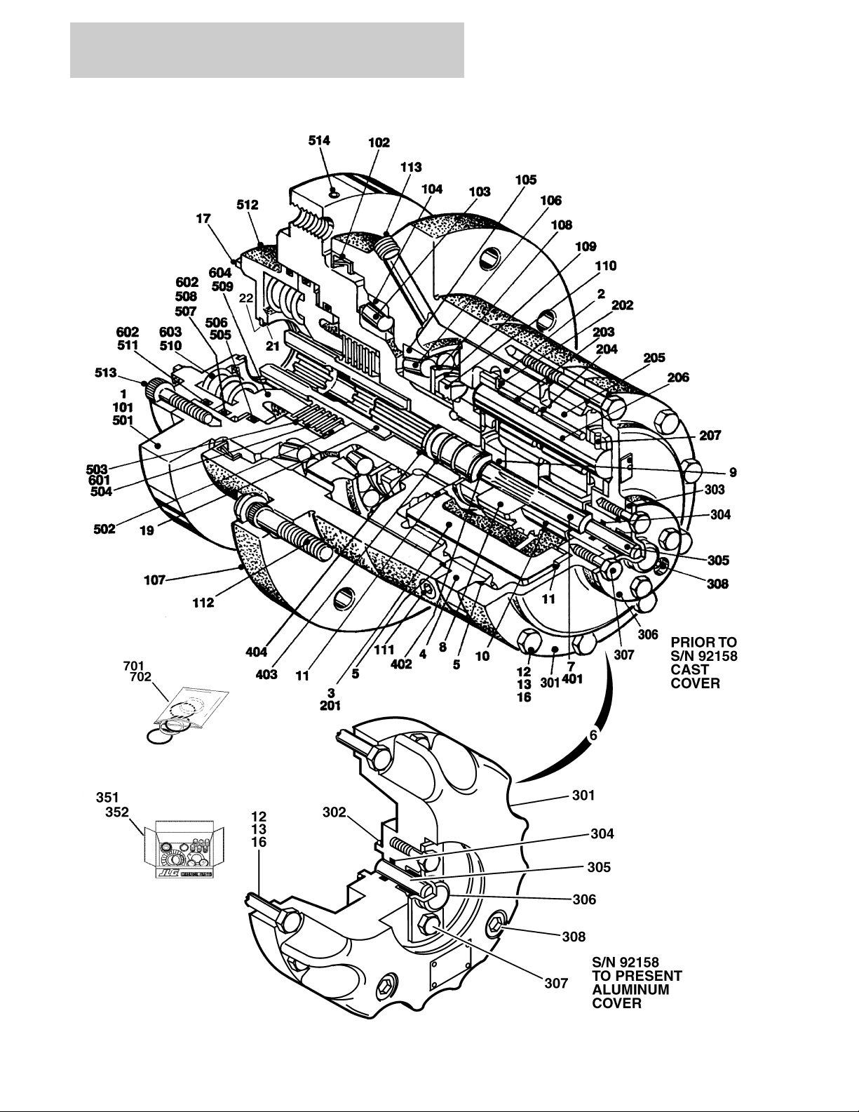
FIGURE 1-7. DRIVE HUB/BRAKE ASSEMBLIES
1-24 400RTS 500RTS 3120697
 Loading...