


Service and Maintenance Manual
Model
340AJ
P/N - 3121259
July 9, 2013


SECTION A. INTRODUCTION - MAINTENANCE SAFETY PRECAUTIONS
INTRODUCTION
AGENERAL
This section contains the general safety precautions which
must be observed during maintenance of the aerial platform.
It is of utmost importance that maintenance personnel pay
strict attention to these warnings and precautions to avoid
possible injury to themselves or others, or damage to the
equipment. A maintenance program must be followed to
ensure that the machine is safe to operate.
MODIFICATION OR ALTERATION OF AN AERIAL WORK PLATFORM SHALL BE
MADE ONLY WITH WRITTEN PERMISSION FROM THE MANUFACTURER.
The specific precautions to be observed during maintenance
are inserted at the appropriate point in the manual. These precautions are, for the most part, those that apply when servicing hydraulic and larger machine component parts.
Your safety, and that of others, is the first consideration when
engaging in the maintenance of equipment. Always be conscious of weight. Never attempt to move heavy parts without
the aid of a mechanical device. Do not allow heavy objects to
rest in an unstable position. When raising a portion of the
equipment, ensure that adequate support is provided.
CMAINTENANCE
FAILURE TO COMPLY WITH SAFETY PRECAUTIONS LISTED IN THIS SECTION
COULD RESULT IN MACHINE DAMAGE, PERSONNEL INJURY OR DEATH AND IS A
SAFETY VIOLATION.
• ENSURE REPLACEMENT PARTS OR COMPONENTS ARE
IDENTICAL OR EQUIVALENT TO ORIGINAL PARTS OR
COMPONENTS.
• NO SMOKING IS MANDATORY. NEVER REFUEL DURING ELECTRICAL STORMS. ENSURE THAT FUEL CAP IS CLOSED AND
SECURE AT ALL OTHER TIMES.
• REMOVE ALL RINGS, WATCHES AND JEWELRY WHEN PERFORMING ANY MAINTENANCE.
• DO NOT WEAR LONG HAIR UNRESTRAINED, OR LOOSE-FITTING CLOTHING AND NECKTIES WHICH ARE APT TO BECOME
CAUGHT ON OR ENTANGLED IN EQUIPMENT.
• OBSERVE AND OBEY ALL WARNINGS AND CAUTIONS ON
MACHINE AND IN SERVICE MANUAL.
• KEEP OIL, GREASE, WATER, ETC. WIPED FROM STANDING
SURFACES AND HAND HOLDS.
• USE CAUTION WHEN CHECKING A HOT, PRESSURIZED COOLANT SYSTEM.
SINCE THE MACHINE MANUFACTURER HAS NO DIRECT CONTROL OVER THE
FIELD INSPECTION AND MAINTENANCE, SAFETY IN THIS AREA RESPONSIBIL-
ITY OF THE OWNER/OPERATOR.
BHYDRAULIC SYSTEM SAFETY
It should be noted that the machines hydraulic systems operate at extremely high potentially dangerous pressures. Every
effort should be made to relieve any system pressure prior to
disconnecting or removing any portion of the system.
• NEVER WORK UNDER AN ELEVATED BOOM UNTIL BOOM HAS
BEEN SAFELY RESTRAINED FROM ANY MOVEMENT BY
BLOCKING OR OVERHEAD SLING, OR BOOM SAFETY PROP
HAS BEEN ENGAGED.
• BEFORE MAKING ADJUSTMENTS, LUBRICATING OR PERFORMING ANY OTHER MAINTENANCE, SHUT OFF ALL
POWER CONTROLS.
• BATTERY SHOULD ALWAYS BE DISCONNECTEDDURING
REPLACEMENT OF ELECTRICAL COMPONENTS.
• KEEP ALL SUPPORT EQUIPMENT AND ATTACHMENTS
STOWED IN THEIR PROPER PLACE.
• USE ONLY APPROVED, NONFLAMMABLE CLEANING SOLVENTS.
3121259 – JLG Lift – A-1

INTRODUCTION
Original Issue - May 6, 2011
Revised - January 17, 2012
Revised - July 9, 2013
REVISON LOG
A-2 – JLG Lift – 3121259

TABLE OF CONTENTS
SECTION NO. TITLE PAGE NO.
SECTION A - INTRODUCTION - MAINTENANCE SAFETY PRECAUTIONS
A General . . . . . . . . . . . . . . . . . . . . . . . . . . . . . . . . . . . . . . . . . . . . . . . . . . . . . . . . . . . . . . . . . . . . . . . . . . . . . . . . . . . . . . . . . . . . A-1
B Hydraulic System Safety . . . . . . . . . . . . . . . . . . . . . . . . . . . . . . . . . . . . . . . . . . . . . . . . . . . . . . . . . . . . . . . . . . . . . . . . . . . . A-1
C Maintenance. . . . . . . . . . . . . . . . . . . . . . . . . . . . . . . . . . . . . . . . . . . . . . . . . . . . . . . . . . . . . . . . . . . . . . . . . . . . . . . . . . . . . . . A-1
SECTION 1 - SPECIFICATIONS
1.1 Operating Specifications . . . . . . . . . . . . . . . . . . . . . . . . . . . . . . . . . . . . . . . . . . . . . . . . . . . . . . . . . . . . . . . . . . . . . . . . . . . 1-1
1.2 Dimensional Data . . . . . . . . . . . . . . . . . . . . . . . . . . . . . . . . . . . . . . . . . . . . . . . . . . . . . . . . . . . . . . . . . . . . . . . . . . . . . . . . . . 1-1
1.3 Capacities . . . . . . . . . . . . . . . . . . . . . . . . . . . . . . . . . . . . . . . . . . . . . . . . . . . . . . . . . . . . . . . . . . . . . . . . . . . . . . . . . . . . . . . . . 1-1
1.4 Tires . . . . . . . . . . . . . . . . . . . . . . . . . . . . . . . . . . . . . . . . . . . . . . . . . . . . . . . . . . . . . . . . . . . . . . . . . . . . . . . . . . . . . . . . . . . . . . . 1-1
1.5 Engine Data. . . . . . . . . . . . . . . . . . . . . . . . . . . . . . . . . . . . . . . . . . . . . . . . . . . . . . . . . . . . . . . . . . . . . . . . . . . . . . . . . . . . . . . . 1-1
Hydraulic Oil . . . . . . . . . . . . . . . . . . . . . . . . . . . . . . . . . . . . . . . . . . . . . . . . . . . . . . . . . . . . . . . . . . . . . . . . . . . . . . . . . . 1-2
Major Component Weights . . . . . . . . . . . . . . . . . . . . . . . . . . . . . . . . . . . . . . . . . . . . . . . . . . . . . . . . . . . . . . . . . . . . 1-2
1.6 Function Speeds . . . . . . . . . . . . . . . . . . . . . . . . . . . . . . . . . . . . . . . . . . . . . . . . . . . . . . . . . . . . . . . . . . . . . . . . . . . . . . . . . . . 1-3
Test Notes . . . . . . . . . . . . . . . . . . . . . . . . . . . . . . . . . . . . . . . . . . . . . . . . . . . . . . . . . . . . . . . . . . . . . . . . . . . . . . . . . . . . 1-3
1.7 Operator Maintenance . . . . . . . . . . . . . . . . . . . . . . . . . . . . . . . . . . . . . . . . . . . . . . . . . . . . . . . . . . . . . . . . . . . . . . . . . . . . . 1-5
SECTION 2 - GENERAL
2.1 Machine Preparation, Inspection, and Maintenance . . . . . . . . . . . . . . . . . . . . . . . . . . . . . . . . . . . . . . . . . . . . . . . . . 2-1
General . . . . . . . . . . . . . . . . . . . . . . . . . . . . . . . . . . . . . . . . . . . . . . . . . . . . . . . . . . . . . . . . . . . . . . . . . . . . . . . . . . . . . . . 2-1
Preparation, Inspection, and Maintenance . . . . . . . . . . . . . . . . . . . . . . . . . . . . . . . . . . . . . . . . . . . . . . . . . . . . . 2-1
Pre-Start Inspection . . . . . . . . . . . . . . . . . . . . . . . . . . . . . . . . . . . . . . . . . . . . . . . . . . . . . . . . . . . . . . . . . . . . . . . . . . . 2-1
Pre-Delivery Inspection and Frequent Inspection. . . . . . . . . . . . . . . . . . . . . . . . . . . . . . . . . . . . . . . . . . . . . . . 2-1
Annual Machine Inspection. . . . . . . . . . . . . . . . . . . . . . . . . . . . . . . . . . . . . . . . . . . . . . . . . . . . . . . . . . . . . . . . . . . . 2-1
Preventive Maintenance. . . . . . . . . . . . . . . . . . . . . . . . . . . . . . . . . . . . . . . . . . . . . . . . . . . . . . . . . . . . . . . . . . . . . . . 2-1
2.2 Service and Guidelines . . . . . . . . . . . . . . . . . . . . . . . . . . . . . . . . . . . . . . . . . . . . . . . . . . . . . . . . . . . . . . . . . . . . . . . . . . . . . 2-2
General . . . . . . . . . . . . . . . . . . . . . . . . . . . . . . . . . . . . . . . . . . . . . . . . . . . . . . . . . . . . . . . . . . . . . . . . . . . . . . . . . . . . . . . 2-2
Safety and Workmanship . . . . . . . . . . . . . . . . . . . . . . . . . . . . . . . . . . . . . . . . . . . . . . . . . . . . . . . . . . . . . . . . . . . . . . 2-2
Cleanliness. . . . . . . . . . . . . . . . . . . . . . . . . . . . . . . . . . . . . . . . . . . . . . . . . . . . . . . . . . . . . . . . . . . . . . . . . . . . . . . . . . . . 2-2
Components Removal and Installation. . . . . . . . . . . . . . . . . . . . . . . . . . . . . . . . . . . . . . . . . . . . . . . . . . . . . . . . . 2-2
Component Disassembly and Reassembly . . . . . . . . . . . . . . . . . . . . . . . . . . . . . . . . . . . . . . . . . . . . . . . . . . . . . 2-3
Pressure-Fit Parts. . . . . . . . . . . . . . . . . . . . . . . . . . . . . . . . . . . . . . . . . . . . . . . . . . . . . . . . . . . . . . . . . . . . . . . . . . . . . . 2-3
Bearings . . . . . . . . . . . . . . . . . . . . . . . . . . . . . . . . . . . . . . . . . . . . . . . . . . . . . . . . . . . . . . . . . . . . . . . . . . . . . . . . . . . . . . 2-3
Gaskets . . . . . . . . . . . . . . . . . . . . . . . . . . . . . . . . . . . . . . . . . . . . . . . . . . . . . . . . . . . . . . . . . . . . . . . . . . . . . . . . . . . . . . . 2-3
Bolt Usage and Torque Application . . . . . . . . . . . . . . . . . . . . . . . . . . . . . . . . . . . . . . . . . . . . . . . . . . . . . . . . . . . . 2-3
Hydraulic Lines and Electrical Wiring. . . . . . . . . . . . . . . . . . . . . . . . . . . . . . . . . . . . . . . . . . . . . . . . . . . . . . . . . . . 2-3
Hydraulic System. . . . . . . . . . . . . . . . . . . . . . . . . . . . . . . . . . . . . . . . . . . . . . . . . . . . . . . . . . . . . . . . . . . . . . . . . . . . . . 2-3
Lubrication . . . . . . . . . . . . . . . . . . . . . . . . . . . . . . . . . . . . . . . . . . . . . . . . . . . . . . . . . . . . . . . . . . . . . . . . . . . . . . . . . . . 2-3
Battery. . . . . . . . . . . . . . . . . . . . . . . . . . . . . . . . . . . . . . . . . . . . . . . . . . . . . . . . . . . . . . . . . . . . . . . . . . . . . . . . . . . . . . . . 2-3
Lubrication and Servicing . . . . . . . . . . . . . . . . . . . . . . . . . . . . . . . . . . . . . . . . . . . . . . . . . . . . . . . . . . . . . . . . . . . . . 2-3
2.3 Lubrication and Information. . . . . . . . . . . . . . . . . . . . . . . . . . . . . . . . . . . . . . . . . . . . . . . . . . . . . . . . . . . . . . . . . . . . . . . . 2-3
Hydraulic System. . . . . . . . . . . . . . . . . . . . . . . . . . . . . . . . . . . . . . . . . . . . . . . . . . . . . . . . . . . . . . . . . . . . . . . . . . . . . . 2-3
Hydraulic Oil . . . . . . . . . . . . . . . . . . . . . . . . . . . . . . . . . . . . . . . . . . . . . . . . . . . . . . . . . . . . . . . . . . . . . . . . . . . . . . . . . . 2-4
Changing Hydraulic Oil. . . . . . . . . . . . . . . . . . . . . . . . . . . . . . . . . . . . . . . . . . . . . . . . . . . . . . . . . . . . . . . . . . . . . . . . 2-4
Lubrication Specifications . . . . . . . . . . . . . . . . . . . . . . . . . . . . . . . . . . . . . . . . . . . . . . . . . . . . . . . . . . . . . . . . . . . . . 2-4
3121259 – JLG Lift – i

TABLE OF CONTENTS
SECTION NO. TITLE PAGE NO.
2.4 Cylinder Drift Test . . . . . . . . . . . . . . . . . . . . . . . . . . . . . . . . . . . . . . . . . . . . . . . . . . . . . . . . . . . . . . . . . . . . . . . . . . . . . . . . . . 2-4
Platform Drift. . . . . . . . . . . . . . . . . . . . . . . . . . . . . . . . . . . . . . . . . . . . . . . . . . . . . . . . . . . . . . . . . . . . . . . . . . . . . . . . . 2-4
Cylinder Drift . . . . . . . . . . . . . . . . . . . . . . . . . . . . . . . . . . . . . . . . . . . . . . . . . . . . . . . . . . . . . . . . . . . . . . . . . . . . . . . . . 2-5
2.5 Pins and Composite Bearing Repair Guidelines . . . . . . . . . . . . . . . . . . . . . . . . . . . . . . . . . . . . . . . . . . . . . . . . . . . . . . 2-5
2.6 Welding on JLG Equipment . . . . . . . . . . . . . . . . . . . . . . . . . . . . . . . . . . . . . . . . . . . . . . . . . . . . . . . . . . . . . . . . . . . . . . . . . 2-5
Do the Following When Welding on JLG Equipment . . . . . . . . . . . . . . . . . . . . . . . . . . . . . . . . . . . . . . . . . . . 2-5
Do NOT Do the Following When Welding on JLG Equipment. . . . . . . . . . . . . . . . . . . . . . . . . . . . . . . . . . . 2-5
SECTION 3 - CHASSIS & TURNTABLE
3.1 Tires and Wheels . . . . . . . . . . . . . . . . . . . . . . . . . . . . . . . . . . . . . . . . . . . . . . . . . . . . . . . . . . . . . . . . . . . . . . . . . . . . . . . . . . . 3-1
Tire Replacement. . . . . . . . . . . . . . . . . . . . . . . . . . . . . . . . . . . . . . . . . . . . . . . . . . . . . . . . . . . . . . . . . . . . . . . . . . . . . 3-1
Wheel and Tire Replacement. . . . . . . . . . . . . . . . . . . . . . . . . . . . . . . . . . . . . . . . . . . . . . . . . . . . . . . . . . . . . . . . . . 3-1
Wheel Installation . . . . . . . . . . . . . . . . . . . . . . . . . . . . . . . . . . . . . . . . . . . . . . . . . . . . . . . . . . . . . . . . . . . . . . . . . . . . 3-1
3.2 Drive Orientation System . . . . . . . . . . . . . . . . . . . . . . . . . . . . . . . . . . . . . . . . . . . . . . . . . . . . . . . . . . . . . . . . . . . . . . . . . . . 3-2
3.3 Beyond Transport Position - Drive Speed Cutback System . . . . . . . . . . . . . . . . . . . . . . . . . . . . . . . . . . . . . . . . . . . 3-2
3.4 Drive/Steer - Boom Function Interlock System (CE ONLY) . . . . . . . . . . . . . . . . . . . . . . . . . . . . . . . . . . . . . . . . . . . . 3-2
3.5 Drive System . . . . . . . . . . . . . . . . . . . . . . . . . . . . . . . . . . . . . . . . . . . . . . . . . . . . . . . . . . . . . . . . . . . . . . . . . . . . . . . . . . . . . . . 3-2
3.6 Drive Motor . . . . . . . . . . . . . . . . . . . . . . . . . . . . . . . . . . . . . . . . . . . . . . . . . . . . . . . . . . . . . . . . . . . . . . . . . . . . . . . . . . . . . . . . 3-3
Disassembly. . . . . . . . . . . . . . . . . . . . . . . . . . . . . . . . . . . . . . . . . . . . . . . . . . . . . . . . . . . . . . . . . . . . . . . . . . . . . . . . . . 3-3
Assembly . . . . . . . . . . . . . . . . . . . . . . . . . . . . . . . . . . . . . . . . . . . . . . . . . . . . . . . . . . . . . . . . . . . . . . . . . . . . . . . . . . . . 3-3
3.7 Drive Hub . . . . . . . . . . . . . . . . . . . . . . . . . . . . . . . . . . . . . . . . . . . . . . . . . . . . . . . . . . . . . . . . . . . . . . . . . . . . . . . . . . . . . . . . . . 3-10
Roll, Leak and Brake Testing. . . . . . . . . . . . . . . . . . . . . . . . . . . . . . . . . . . . . . . . . . . . . . . . . . . . . . . . . . . . . . . . . . . 3-10
Tightening and Torquing Bolts. . . . . . . . . . . . . . . . . . . . . . . . . . . . . . . . . . . . . . . . . . . . . . . . . . . . . . . . . . . . . . . . 3-10
Measuring Rolling Torque . . . . . . . . . . . . . . . . . . . . . . . . . . . . . . . . . . . . . . . . . . . . . . . . . . . . . . . . . . . . . . . . . . . . 3-11
Main Disassembly . . . . . . . . . . . . . . . . . . . . . . . . . . . . . . . . . . . . . . . . . . . . . . . . . . . . . . . . . . . . . . . . . . . . . . . . . . . . 3-11
Housing-Spindle Disassembly. . . . . . . . . . . . . . . . . . . . . . . . . . . . . . . . . . . . . . . . . . . . . . . . . . . . . . . . . . . . . . . . . 3-13
Spindle-Brake Subassembly Disassembly. . . . . . . . . . . . . . . . . . . . . . . . . . . . . . . . . . . . . . . . . . . . . . . . . . . . . . 3-15
Cover Disassembly . . . . . . . . . . . . . . . . . . . . . . . . . . . . . . . . . . . . . . . . . . . . . . . . . . . . . . . . . . . . . . . . . . . . . . . . . . . 3-16
Planet Gear Subassembly . . . . . . . . . . . . . . . . . . . . . . . . . . . . . . . . . . . . . . . . . . . . . . . . . . . . . . . . . . . . . . . . . . . . . 3-18
Spindle-Brake Subassembly. . . . . . . . . . . . . . . . . . . . . . . . . . . . . . . . . . . . . . . . . . . . . . . . . . . . . . . . . . . . . . . . . . . 3-19
Housing-Spindle Subassembly . . . . . . . . . . . . . . . . . . . . . . . . . . . . . . . . . . . . . . . . . . . . . . . . . . . . . . . . . . . . . . . . 3-21
Housing-Ring Gear Subassembly. . . . . . . . . . . . . . . . . . . . . . . . . . . . . . . . . . . . . . . . . . . . . . . . . . . . . . . . . . . . . . 3-22
Cover Subassembly. . . . . . . . . . . . . . . . . . . . . . . . . . . . . . . . . . . . . . . . . . . . . . . . . . . . . . . . . . . . . . . . . . . . . . . . . . . 3-23
Main Assembly . . . . . . . . . . . . . . . . . . . . . . . . . . . . . . . . . . . . . . . . . . . . . . . . . . . . . . . . . . . . . . . . . . . . . . . . . . . . . . . 3-24
Integral Brake Check Procedure . . . . . . . . . . . . . . . . . . . . . . . . . . . . . . . . . . . . . . . . . . . . . . . . . . . . . . . . . . . . . . . 3-25
3.8 Oscillating Axle System . . . . . . . . . . . . . . . . . . . . . . . . . . . . . . . . . . . . . . . . . . . . . . . . . . . . . . . . . . . . . . . . . . . . . . . . . . . . . 3-30
Oscillating Axle Bleeding Procedure. . . . . . . . . . . . . . . . . . . . . . . . . . . . . . . . . . . . . . . . . . . . . . . . . . . . . . . . . . . 3-30
3.9 Chassis Tilt Indicator System . . . . . . . . . . . . . . . . . . . . . . . . . . . . . . . . . . . . . . . . . . . . . . . . . . . . . . . . . . . . . . . . . . . . . . . . 3-32
3.10 Swing Motor . . . . . . . . . . . . . . . . . . . . . . . . . . . . . . . . . . . . . . . . . . . . . . . . . . . . . . . . . . . . . . . . . . . . . . . . . . . . . . . . . . . . . . . 3-32
Removal . . . . . . . . . . . . . . . . . . . . . . . . . . . . . . . . . . . . . . . . . . . . . . . . . . . . . . . . . . . . . . . . . . . . . . . . . . . . . . . . . . . . . 3-34
Preparation Before Disassembly. . . . . . . . . . . . . . . . . . . . . . . . . . . . . . . . . . . . . . . . . . . . . . . . . . . . . . . . . . . . . . . 3-34
Disassembly and Inspection . . . . . . . . . . . . . . . . . . . . . . . . . . . . . . . . . . . . . . . . . . . . . . . . . . . . . . . . . . . . . . . . . . 3-35
Assembly . . . . . . . . . . . . . . . . . . . . . . . . . . . . . . . . . . . . . . . . . . . . . . . . . . . . . . . . . . . . . . . . . . . . . . . . . . . . . . . . . . . . 3-42
One Piece Stator Construction . . . . . . . . . . . . . . . . . . . . . . . . . . . . . . . . . . . . . . . . . . . . . . . . . . . . . . . . . . . . . . . . 3-48
Two Piece Stator Construction . . . . . . . . . . . . . . . . . . . . . . . . . . . . . . . . . . . . . . . . . . . . . . . . . . . . . . . . . . . . . . . . 3-49
Final Checks. . . . . . . . . . . . . . . . . . . . . . . . . . . . . . . . . . . . . . . . . . . . . . . . . . . . . . . . . . . . . . . . . . . . . . . . . . . . . . . . . . 3-50
Installation . . . . . . . . . . . . . . . . . . . . . . . . . . . . . . . . . . . . . . . . . . . . . . . . . . . . . . . . . . . . . . . . . . . . . . . . . . . . . . . . . . . 3-50
ii – JLG Lift – 3121259

TABLE OF CONTENTS
SECTION NO. TITLE PAGE NO.
3.11 Swing Drive. . . . . . . . . . . . . . . . . . . . . . . . . . . . . . . . . . . . . . . . . . . . . . . . . . . . . . . . . . . . . . . . . . . . . . . . . . . . . . . . . . . . . . . . 3-50
Removal . . . . . . . . . . . . . . . . . . . . . . . . . . . . . . . . . . . . . . . . . . . . . . . . . . . . . . . . . . . . . . . . . . . . . . . . . . . . . . . . . . . . . . 3-50
Installation. . . . . . . . . . . . . . . . . . . . . . . . . . . . . . . . . . . . . . . . . . . . . . . . . . . . . . . . . . . . . . . . . . . . . . . . . . . . . . . . . . . . 3-55
Turntable Bearing Mounting Bolt Condition Check . . . . . . . . . . . . . . . . . . . . . . . . . . . . . . . . . . . . . . . . . . . . . 3-56
Wear Tolerance . . . . . . . . . . . . . . . . . . . . . . . . . . . . . . . . . . . . . . . . . . . . . . . . . . . . . . . . . . . . . . . . . . . . . . . . . . . . . . . 3-56
Swing Bearing Torque Value. . . . . . . . . . . . . . . . . . . . . . . . . . . . . . . . . . . . . . . . . . . . . . . . . . . . . . . . . . . . . . . . . . . 3-56
Disassembly . . . . . . . . . . . . . . . . . . . . . . . . . . . . . . . . . . . . . . . . . . . . . . . . . . . . . . . . . . . . . . . . . . . . . . . . . . . . . . . . . . 3-58
Assembly . . . . . . . . . . . . . . . . . . . . . . . . . . . . . . . . . . . . . . . . . . . . . . . . . . . . . . . . . . . . . . . . . . . . . . . . . . . . . . . . . . . . . 3-60
3.12 Engine Operating States. . . . . . . . . . . . . . . . . . . . . . . . . . . . . . . . . . . . . . . . . . . . . . . . . . . . . . . . . . . . . . . . . . . . . . . . . . . . 3-69
3.13 Engine Start Conditions . . . . . . . . . . . . . . . . . . . . . . . . . . . . . . . . . . . . . . . . . . . . . . . . . . . . . . . . . . . . . . . . . . . . . . . . . . . . 3-70
3.14 Engine rPM Levels. . . . . . . . . . . . . . . . . . . . . . . . . . . . . . . . . . . . . . . . . . . . . . . . . . . . . . . . . . . . . . . . . . . . . . . . . . . . . . . . . . 3-70
Engine Stop RPM. . . . . . . . . . . . . . . . . . . . . . . . . . . . . . . . . . . . . . . . . . . . . . . . . . . . . . . . . . . . . . . . . . . . . . . . . . . . . . 3-70
Idle RPM . . . . . . . . . . . . . . . . . . . . . . . . . . . . . . . . . . . . . . . . . . . . . . . . . . . . . . . . . . . . . . . . . . . . . . . . . . . . . . . . . . . . . . 3-70
Mid Engine RPM . . . . . . . . . . . . . . . . . . . . . . . . . . . . . . . . . . . . . . . . . . . . . . . . . . . . . . . . . . . . . . . . . . . . . . . . . . . . . . 3-70
Multi-Function RPM . . . . . . . . . . . . . . . . . . . . . . . . . . . . . . . . . . . . . . . . . . . . . . . . . . . . . . . . . . . . . . . . . . . . . . . . . . . 3-71
High Engine RPM. . . . . . . . . . . . . . . . . . . . . . . . . . . . . . . . . . . . . . . . . . . . . . . . . . . . . . . . . . . . . . . . . . . . . . . . . . . . . . 3-71
Generator RPM. . . . . . . . . . . . . . . . . . . . . . . . . . . . . . . . . . . . . . . . . . . . . . . . . . . . . . . . . . . . . . . . . . . . . . . . . . . . . . . . 3-71
3.15 Engine controls . . . . . . . . . . . . . . . . . . . . . . . . . . . . . . . . . . . . . . . . . . . . . . . . . . . . . . . . . . . . . . . . . . . . . . . . . . . . . . . . . . . . 3-71
Ambient Air Temperature Sensor . . . . . . . . . . . . . . . . . . . . . . . . . . . . . . . . . . . . . . . . . . . . . . . . . . . . . . . . . . . . . . 3-71
Fuel Level Sensor . . . . . . . . . . . . . . . . . . . . . . . . . . . . . . . . . . . . . . . . . . . . . . . . . . . . . . . . . . . . . . . . . . . . . . . . . . . . . 3-71
3.16 Engine Startup Procedure (Kubota) . . . . . . . . . . . . . . . . . . . . . . . . . . . . . . . . . . . . . . . . . . . . . . . . . . . . . . . . . . . . . . . . . 3-72
3.17 Kubota Engine . . . . . . . . . . . . . . . . . . . . . . . . . . . . . . . . . . . . . . . . . . . . . . . . . . . . . . . . . . . . . . . . . . . . . . . . . . . . . . . . . . . . . 3-73
Engine Oil Pressure Switch . . . . . . . . . . . . . . . . . . . . . . . . . . . . . . . . . . . . . . . . . . . . . . . . . . . . . . . . . . . . . . . . . . . . 3-73
Engine Speed Sensor. . . . . . . . . . . . . . . . . . . . . . . . . . . . . . . . . . . . . . . . . . . . . . . . . . . . . . . . . . . . . . . . . . . . . . . . . . 3-73
Coolant Sensor. . . . . . . . . . . . . . . . . . . . . . . . . . . . . . . . . . . . . . . . . . . . . . . . . . . . . . . . . . . . . . . . . . . . . . . . . . . . . . . . 3-74
Glow Plugs. . . . . . . . . . . . . . . . . . . . . . . . . . . . . . . . . . . . . . . . . . . . . . . . . . . . . . . . . . . . . . . . . . . . . . . . . . . . . . . . . . . . 3-74
Engine Speed Actuators . . . . . . . . . . . . . . . . . . . . . . . . . . . . . . . . . . . . . . . . . . . . . . . . . . . . . . . . . . . . . . . . . . . . . . . 3-75
Engine Start. . . . . . . . . . . . . . . . . . . . . . . . . . . . . . . . . . . . . . . . . . . . . . . . . . . . . . . . . . . . . . . . . . . . . . . . . . . . . . . . . . . 3-76
Alternator Excitation . . . . . . . . . . . . . . . . . . . . . . . . . . . . . . . . . . . . . . . . . . . . . . . . . . . . . . . . . . . . . . . . . . . . . . . . . . 3-76
Fuel Pump . . . . . . . . . . . . . . . . . . . . . . . . . . . . . . . . . . . . . . . . . . . . . . . . . . . . . . . . . . . . . . . . . . . . . . . . . . . . . . . . . . . . 3-76
Shutdown . . . . . . . . . . . . . . . . . . . . . . . . . . . . . . . . . . . . . . . . . . . . . . . . . . . . . . . . . . . . . . . . . . . . . . . . . . . . . . . . . . . . 3-76
3.18 GM Dual Fuel Engine . . . . . . . . . . . . . . . . . . . . . . . . . . . . . . . . . . . . . . . . . . . . . . . . . . . . . . . . . . . . . . . . . . . . . . . . . . . . . . . 3-81
Communications with the JLG Control System . . . . . . . . . . . . . . . . . . . . . . . . . . . . . . . . . . . . . . . . . . . . . . . . . 3-81
Engine Start. . . . . . . . . . . . . . . . . . . . . . . . . . . . . . . . . . . . . . . . . . . . . . . . . . . . . . . . . . . . . . . . . . . . . . . . . . . . . . . . . . . 3-81
Oil Pressure . . . . . . . . . . . . . . . . . . . . . . . . . . . . . . . . . . . . . . . . . . . . . . . . . . . . . . . . . . . . . . . . . . . . . . . . . . . . . . . . . . . 3-81
Engine Speed . . . . . . . . . . . . . . . . . . . . . . . . . . . . . . . . . . . . . . . . . . . . . . . . . . . . . . . . . . . . . . . . . . . . . . . . . . . . . . . . . 3-81
Coolant Temperature . . . . . . . . . . . . . . . . . . . . . . . . . . . . . . . . . . . . . . . . . . . . . . . . . . . . . . . . . . . . . . . . . . . . . . . . . 3-81
Fuel Select . . . . . . . . . . . . . . . . . . . . . . . . . . . . . . . . . . . . . . . . . . . . . . . . . . . . . . . . . . . . . . . . . . . . . . . . . . . . . . . . . . . . 3-81
3.19 Fuel Reserve / Cut-Out System. . . . . . . . . . . . . . . . . . . . . . . . . . . . . . . . . . . . . . . . . . . . . . . . . . . . . . . . . . . . . . . . . . . . . . 3-90
3.20 Cold Start System (Diesel Engine). . . . . . . . . . . . . . . . . . . . . . . . . . . . . . . . . . . . . . . . . . . . . . . . . . . . . . . . . . . . . . . . . . . 3-90
3.21 Generator . . . . . . . . . . . . . . . . . . . . . . . . . . . . . . . . . . . . . . . . . . . . . . . . . . . . . . . . . . . . . . . . . . . . . . . . . . . . . . . . . . . . . . . . . 3-90
3.22 Counterweight. . . . . . . . . . . . . . . . . . . . . . . . . . . . . . . . . . . . . . . . . . . . . . . . . . . . . . . . . . . . . . . . . . . . . . . . . . . . . . . . . . . . . 3-91
3121259 – JLG Lift – iii

TABLE OF CONTENTS
SECTION NO. TITLE PAGE NO.
SECTION 4 - BOOM & PLATFORM
4.1 Platform Control Enable System . . . . . . . . . . . . . . . . . . . . . . . . . . . . . . . . . . . . . . . . . . . . . . . . . . . . . . . . . . . . . . . . . . . . 4-1
4.2 Transport Position Sensing System. . . . . . . . . . . . . . . . . . . . . . . . . . . . . . . . . . . . . . . . . . . . . . . . . . . . . . . . . . . . . . . . . . 4-1
4.3 Boom Maintenance. . . . . . . . . . . . . . . . . . . . . . . . . . . . . . . . . . . . . . . . . . . . . . . . . . . . . . . . . . . . . . . . . . . . . . . . . . . . . . . . . 4-1
Disassembly of the Main Boom . . . . . . . . . . . . . . . . . . . . . . . . . . . . . . . . . . . . . . . . . . . . . . . . . . . . . . . . . . . . . . . 4-1
Inspection. . . . . . . . . . . . . . . . . . . . . . . . . . . . . . . . . . . . . . . . . . . . . . . . . . . . . . . . . . . . . . . . . . . . . . . . . . . . . . . . . . . . 4-3
Assembly of the Main Boom . . . . . . . . . . . . . . . . . . . . . . . . . . . . . . . . . . . . . . . . . . . . . . . . . . . . . . . . . . . . . . . . . . 4-3
4.4 Boom Cleanliness Guidelines . . . . . . . . . . . . . . . . . . . . . . . . . . . . . . . . . . . . . . . . . . . . . . . . . . . . . . . . . . . . . . . . . . . . . . . 4-7
4.5 Rotary Actuator . . . . . . . . . . . . . . . . . . . . . . . . . . . . . . . . . . . . . . . . . . . . . . . . . . . . . . . . . . . . . . . . . . . . . . . . . . . . . . . . . . . . 4-10
Theory of Operation . . . . . . . . . . . . . . . . . . . . . . . . . . . . . . . . . . . . . . . . . . . . . . . . . . . . . . . . . . . . . . . . . . . . . . . . . . 4-10
Tools Required . . . . . . . . . . . . . . . . . . . . . . . . . . . . . . . . . . . . . . . . . . . . . . . . . . . . . . . . . . . . . . . . . . . . . . . . . . . . . . . 4-11
Disassembly. . . . . . . . . . . . . . . . . . . . . . . . . . . . . . . . . . . . . . . . . . . . . . . . . . . . . . . . . . . . . . . . . . . . . . . . . . . . . . . . . . 4-12
Inspection. . . . . . . . . . . . . . . . . . . . . . . . . . . . . . . . . . . . . . . . . . . . . . . . . . . . . . . . . . . . . . . . . . . . . . . . . . . . . . . . . . . . 4-17
Assembly . . . . . . . . . . . . . . . . . . . . . . . . . . . . . . . . . . . . . . . . . . . . . . . . . . . . . . . . . . . . . . . . . . . . . . . . . . . . . . . . . . . . 4-18
Greasing Thrust Washers . . . . . . . . . . . . . . . . . . . . . . . . . . . . . . . . . . . . . . . . . . . . . . . . . . . . . . . . . . . . . . . . . . . . . 4-22
Installing Counterbalance Valve. . . . . . . . . . . . . . . . . . . . . . . . . . . . . . . . . . . . . . . . . . . . . . . . . . . . . . . . . . . . . . . 4-22
Testing the Actuator. . . . . . . . . . . . . . . . . . . . . . . . . . . . . . . . . . . . . . . . . . . . . . . . . . . . . . . . . . . . . . . . . . . . . . . . . . 4-22
Installation and Bleeding . . . . . . . . . . . . . . . . . . . . . . . . . . . . . . . . . . . . . . . . . . . . . . . . . . . . . . . . . . . . . . . . . . . . . 4-24
Troubleshooting . . . . . . . . . . . . . . . . . . . . . . . . . . . . . . . . . . . . . . . . . . . . . . . . . . . . . . . . . . . . . . . . . . . . . . . . . . . . . 4-25
SECTION 5 - HYDRAULICS
5.1 Lubricating O-Rings in the Hydraulic System . . . . . . . . . . . . . . . . . . . . . . . . . . . . . . . . . . . . . . . . . . . . . . . . . . . . . . . . 5-1
Cup and Brush . . . . . . . . . . . . . . . . . . . . . . . . . . . . . . . . . . . . . . . . . . . . . . . . . . . . . . . . . . . . . . . . . . . . . . . . . . . . . . . 5-1
Dip Method . . . . . . . . . . . . . . . . . . . . . . . . . . . . . . . . . . . . . . . . . . . . . . . . . . . . . . . . . . . . . . . . . . . . . . . . . . . . . . . . . . 5-2
Spray Method . . . . . . . . . . . . . . . . . . . . . . . . . . . . . . . . . . . . . . . . . . . . . . . . . . . . . . . . . . . . . . . . . . . . . . . . . . . . . . . . 5-2
Brush-on Method. . . . . . . . . . . . . . . . . . . . . . . . . . . . . . . . . . . . . . . . . . . . . . . . . . . . . . . . . . . . . . . . . . . . . . . . . . . . . 5-2
5.2 Hydraulic Cylinders. . . . . . . . . . . . . . . . . . . . . . . . . . . . . . . . . . . . . . . . . . . . . . . . . . . . . . . . . . . . . . . . . . . . . . . . . . . . . . . . . 5-3
Disassembly and Assembly Instructions . . . . . . . . . . . . . . . . . . . . . . . . . . . . . . . . . . . . . . . . . . . . . . . . . . . . . . . 5-3
General Information . . . . . . . . . . . . . . . . . . . . . . . . . . . . . . . . . . . . . . . . . . . . . . . . . . . . . . . . . . . . . . . . . . . . . . . . . . 5-3
Standard of Maintenance . . . . . . . . . . . . . . . . . . . . . . . . . . . . . . . . . . . . . . . . . . . . . . . . . . . . . . . . . . . . . . . . . . . . . 5-3
Inspection After Assembly . . . . . . . . . . . . . . . . . . . . . . . . . . . . . . . . . . . . . . . . . . . . . . . . . . . . . . . . . . . . . . . . . . . . 5-3
Disassembly Procedure . . . . . . . . . . . . . . . . . . . . . . . . . . . . . . . . . . . . . . . . . . . . . . . . . . . . . . . . . . . . . . . . . . . . . . . 5-6
Assembly . . . . . . . . . . . . . . . . . . . . . . . . . . . . . . . . . . . . . . . . . . . . . . . . . . . . . . . . . . . . . . . . . . . . . . . . . . . . . . . . . . . . 5-9
5.3 Drive Pump . . . . . . . . . . . . . . . . . . . . . . . . . . . . . . . . . . . . . . . . . . . . . . . . . . . . . . . . . . . . . . . . . . . . . . . . . . . . . . . . . . . . . . . . 5-34
Description. . . . . . . . . . . . . . . . . . . . . . . . . . . . . . . . . . . . . . . . . . . . . . . . . . . . . . . . . . . . . . . . . . . . . . . . . . . . . . . . . . . 5-34
The System Circuit. . . . . . . . . . . . . . . . . . . . . . . . . . . . . . . . . . . . . . . . . . . . . . . . . . . . . . . . . . . . . . . . . . . . . . . . . . . . 5-35
High Pressure Relief Valve (HPRV) and Charge Check. . . . . . . . . . . . . . . . . . . . . . . . . . . . . . . . . . . . . . . . . . . 5-35
Charge Pressure Relief Valve . . . . . . . . . . . . . . . . . . . . . . . . . . . . . . . . . . . . . . . . . . . . . . . . . . . . . . . . . . . . . . . . . . 5-36
Electrical Displacement Control (EDC) . . . . . . . . . . . . . . . . . . . . . . . . . . . . . . . . . . . . . . . . . . . . . . . . . . . . . . . . . 5-37
Disassembly. . . . . . . . . . . . . . . . . . . . . . . . . . . . . . . . . . . . . . . . . . . . . . . . . . . . . . . . . . . . . . . . . . . . . . . . . . . . . . . . . . 5-39
Inspection. . . . . . . . . . . . . . . . . . . . . . . . . . . . . . . . . . . . . . . . . . . . . . . . . . . . . . . . . . . . . . . . . . . . . . . . . . . . . . . . . . . . 5-44
Assembly . . . . . . . . . . . . . . . . . . . . . . . . . . . . . . . . . . . . . . . . . . . . . . . . . . . . . . . . . . . . . . . . . . . . . . . . . . . . . . . . . . . . 5-48
iv – JLG Lift – 3121259

TABLE OF CONTENTS
SECTION NO. TITLE PAGE NO.
Port Locations and Gauge Installation. . . . . . . . . . . . . . . . . . . . . . . . . . . . . . . . . . . . . . . . . . . . . . . . . . . . . . . . . . 5-56
Fastener Size and Torque Chart. . . . . . . . . . . . . . . . . . . . . . . . . . . . . . . . . . . . . . . . . . . . . . . . . . . . . . . . . . . . . . . . 5-57
Plug Size and Torque Chart . . . . . . . . . . . . . . . . . . . . . . . . . . . . . . . . . . . . . . . . . . . . . . . . . . . . . . . . . . . . . . . . . . . . 5-57
Initial Startup Procedures. . . . . . . . . . . . . . . . . . . . . . . . . . . . . . . . . . . . . . . . . . . . . . . . . . . . . . . . . . . . . . . . . . . . . . 5-60
Troubleshooting . . . . . . . . . . . . . . . . . . . . . . . . . . . . . . . . . . . . . . . . . . . . . . . . . . . . . . . . . . . . . . . . . . . . . . . . . . . . . . 5-61
Pump Adjustment. . . . . . . . . . . . . . . . . . . . . . . . . . . . . . . . . . . . . . . . . . . . . . . . . . . . . . . . . . . . . . . . . . . . . . . . . . . . . 5-64
Displacement Limiter Adjustment . . . . . . . . . . . . . . . . . . . . . . . . . . . . . . . . . . . . . . . . . . . . . . . . . . . . . . . . . . . . . 5-67
Control Neutral Adjustment . . . . . . . . . . . . . . . . . . . . . . . . . . . . . . . . . . . . . . . . . . . . . . . . . . . . . . . . . . . . . . . . . . . 5-68
Mechanical Neutral Adjustment . . . . . . . . . . . . . . . . . . . . . . . . . . . . . . . . . . . . . . . . . . . . . . . . . . . . . . . . . . . . . . . 5-69
Removing the Pump . . . . . . . . . . . . . . . . . . . . . . . . . . . . . . . . . . . . . . . . . . . . . . . . . . . . . . . . . . . . . . . . . . . . . . . . . . 5-70
Electric Control Module . . . . . . . . . . . . . . . . . . . . . . . . . . . . . . . . . . . . . . . . . . . . . . . . . . . . . . . . . . . . . . . . . . . . . . . 5-70
Control Solenoids . . . . . . . . . . . . . . . . . . . . . . . . . . . . . . . . . . . . . . . . . . . . . . . . . . . . . . . . . . . . . . . . . . . . . . . . . . . . . 5-71
Shaft Seal, Roller Bearing and Shaft Replacement. . . . . . . . . . . . . . . . . . . . . . . . . . . . . . . . . . . . . . . . . . . . . . . 5-71
Charge Check / HPRV. . . . . . . . . . . . . . . . . . . . . . . . . . . . . . . . . . . . . . . . . . . . . . . . . . . . . . . . . . . . . . . . . . . . . . . . . . 5-73
Charge Pressure Relief Valve. . . . . . . . . . . . . . . . . . . . . . . . . . . . . . . . . . . . . . . . . . . . . . . . . . . . . . . . . . . . . . . . . . . 5-73
Pressure Limiter Valve Replacement . . . . . . . . . . . . . . . . . . . . . . . . . . . . . . . . . . . . . . . . . . . . . . . . . . . . . . . . . . . 5-74
5.4 Gear Pump. . . . . . . . . . . . . . . . . . . . . . . . . . . . . . . . . . . . . . . . . . . . . . . . . . . . . . . . . . . . . . . . . . . . . . . . . . . . . . . . . . . . . . . . . 5-74
Disassembly . . . . . . . . . . . . . . . . . . . . . . . . . . . . . . . . . . . . . . . . . . . . . . . . . . . . . . . . . . . . . . . . . . . . . . . . . . . . . . . . . . 5-74
Troubleshooting . . . . . . . . . . . . . . . . . . . . . . . . . . . . . . . . . . . . . . . . . . . . . . . . . . . . . . . . . . . . . . . . . . . . . . . . . . . . . . 5-84
5.5 Pressure Setting Procedure. . . . . . . . . . . . . . . . . . . . . . . . . . . . . . . . . . . . . . . . . . . . . . . . . . . . . . . . . . . . . . . . . . . . . . . . . 5-85
5.6 Oil Sampling . . . . . . . . . . . . . . . . . . . . . . . . . . . . . . . . . . . . . . . . . . . . . . . . . . . . . . . . . . . . . . . . . . . . . . . . . . . . . . . . . . . . . . . 5-85
Procedure . . . . . . . . . . . . . . . . . . . . . . . . . . . . . . . . . . . . . . . . . . . . . . . . . . . . . . . . . . . . . . . . . . . . . . . . . . . . . . . . . . . . 5-85
SECTION 6 - JLG CONTROL SYSTEM
6.1 JLG Control System Analyzer Kit Instructions . . . . . . . . . . . . . . . . . . . . . . . . . . . . . . . . . . . . . . . . . . . . . . . . . . . . . . . . 6-1
Introduction . . . . . . . . . . . . . . . . . . . . . . . . . . . . . . . . . . . . . . . . . . . . . . . . . . . . . . . . . . . . . . . . . . . . . . . . . . . . . . . . . . 6-1
6.2 analyzer Menu Structure . . . . . . . . . . . . . . . . . . . . . . . . . . . . . . . . . . . . . . . . . . . . . . . . . . . . . . . . . . . . . . . . . . . . . . . . . . . 6-2
6.3 using the hand held analyzer . . . . . . . . . . . . . . . . . . . . . . . . . . . . . . . . . . . . . . . . . . . . . . . . . . . . . . . . . . . . . . . . . . . . . . . 6-3
To Connect the JLG Control System Analyzer. . . . . . . . . . . . . . . . . . . . . . . . . . . . . . . . . . . . . . . . . . . . . . . . . . . 6-3
Using the Analyzer . . . . . . . . . . . . . . . . . . . . . . . . . . . . . . . . . . . . . . . . . . . . . . . . . . . . . . . . . . . . . . . . . . . . . . . . . . . . 6-3
Changing the Access Level of the Hand Held Analyzer. . . . . . . . . . . . . . . . . . . . . . . . . . . . . . . . . . . . . . . . . . 6-4
Adjusting Parameters Using the Hand Held Analyzer . . . . . . . . . . . . . . . . . . . . . . . . . . . . . . . . . . . . . . . . . . . 6-5
Machine Setup . . . . . . . . . . . . . . . . . . . . . . . . . . . . . . . . . . . . . . . . . . . . . . . . . . . . . . . . . . . . . . . . . . . . . . . . . . . . . . . . 6-6
Level Vehicle Description. . . . . . . . . . . . . . . . . . . . . . . . . . . . . . . . . . . . . . . . . . . . . . . . . . . . . . . . . . . . . . . . . . . . . . 6-6
6.4 Operator Controls and Switches . . . . . . . . . . . . . . . . . . . . . . . . . . . . . . . . . . . . . . . . . . . . . . . . . . . . . . . . . . . . . . . . . . . . 6-16
Ground Control Switches . . . . . . . . . . . . . . . . . . . . . . . . . . . . . . . . . . . . . . . . . . . . . . . . . . . . . . . . . . . . . . . . . . . . . . 6-16
Platform Control Switches . . . . . . . . . . . . . . . . . . . . . . . . . . . . . . . . . . . . . . . . . . . . . . . . . . . . . . . . . . . . . . . . . . . . . 6-16
6.5 Control System Startup Checks . . . . . . . . . . . . . . . . . . . . . . . . . . . . . . . . . . . . . . . . . . . . . . . . . . . . . . . . . . . . . . . . . . . . . 6-17
6.6 System Fault Messages. . . . . . . . . . . . . . . . . . . . . . . . . . . . . . . . . . . . . . . . . . . . . . . . . . . . . . . . . . . . . . . . . . . . . . . . . . . . . 6-33
3121259 – JLG Lift – v

TABLE OF CONTENTS
SECTION NO. TITLE PAGE NO.
SECTION 7 - BASIC ELECTRICAL INFORMATION & SCHEMATICS
7.1 General . . . . . . . . . . . . . . . . . . . . . . . . . . . . . . . . . . . . . . . . . . . . . . . . . . . . . . . . . . . . . . . . . . . . . . . . . . . . . . . . . . . . . . . . . . . . 7-1
7.2 Multimeter Basics . . . . . . . . . . . . . . . . . . . . . . . . . . . . . . . . . . . . . . . . . . . . . . . . . . . . . . . . . . . . . . . . . . . . . . . . . . . . . . . . . . 7-1
Grounding . . . . . . . . . . . . . . . . . . . . . . . . . . . . . . . . . . . . . . . . . . . . . . . . . . . . . . . . . . . . . . . . . . . . . . . . . . . . . . . . . . . 7-1
Backprobing . . . . . . . . . . . . . . . . . . . . . . . . . . . . . . . . . . . . . . . . . . . . . . . . . . . . . . . . . . . . . . . . . . . . . . . . . . . . . . . . . 7-1
Min/Max . . . . . . . . . . . . . . . . . . . . . . . . . . . . . . . . . . . . . . . . . . . . . . . . . . . . . . . . . . . . . . . . . . . . . . . . . . . . . . . . . . . . . 7-1
Polarity . . . . . . . . . . . . . . . . . . . . . . . . . . . . . . . . . . . . . . . . . . . . . . . . . . . . . . . . . . . . . . . . . . . . . . . . . . . . . . . . . . . . . . 7-1
Scale . . . . . . . . . . . . . . . . . . . . . . . . . . . . . . . . . . . . . . . . . . . . . . . . . . . . . . . . . . . . . . . . . . . . . . . . . . . . . . . . . . . . . . . . . 7-1
Voltage Measurement . . . . . . . . . . . . . . . . . . . . . . . . . . . . . . . . . . . . . . . . . . . . . . . . . . . . . . . . . . . . . . . . . . . . . . . . 7-1
Resistance Measurement . . . . . . . . . . . . . . . . . . . . . . . . . . . . . . . . . . . . . . . . . . . . . . . . . . . . . . . . . . . . . . . . . . . . . 7-2
Continuity Measurement . . . . . . . . . . . . . . . . . . . . . . . . . . . . . . . . . . . . . . . . . . . . . . . . . . . . . . . . . . . . . . . . . . . . . 7-2
Current Measurement . . . . . . . . . . . . . . . . . . . . . . . . . . . . . . . . . . . . . . . . . . . . . . . . . . . . . . . . . . . . . . . . . . . . . . . . 7-3
7.3 Applying Silicone Dielectric Compound to Electrical Connections . . . . . . . . . . . . . . . . . . . . . . . . . . . . . . . . . . . . 7-3
Installation of Dielectric Grease . . . . . . . . . . . . . . . . . . . . . . . . . . . . . . . . . . . . . . . . . . . . . . . . . . . . . . . . . . . . . . . 7-4
Deutsch HD, DT, DTM, DRC Series . . . . . . . . . . . . . . . . . . . . . . . . . . . . . . . . . . . . . . . . . . . . . . . . . . . . . . . . . . . . . 7-4
AMP Seal . . . . . . . . . . . . . . . . . . . . . . . . . . . . . . . . . . . . . . . . . . . . . . . . . . . . . . . . . . . . . . . . . . . . . . . . . . . . . . . . . . . . . 7-4
AMP Mate-N-Lok . . . . . . . . . . . . . . . . . . . . . . . . . . . . . . . . . . . . . . . . . . . . . . . . . . . . . . . . . . . . . . . . . . . . . . . . . . . . . 7-5
DIN Connectors . . . . . . . . . . . . . . . . . . . . . . . . . . . . . . . . . . . . . . . . . . . . . . . . . . . . . . . . . . . . . . . . . . . . . . . . . . . . . . 7-5
Exclusions. . . . . . . . . . . . . . . . . . . . . . . . . . . . . . . . . . . . . . . . . . . . . . . . . . . . . . . . . . . . . . . . . . . . . . . . . . . . . . . . . . . . 7-5
7.4 AMP Connector . . . . . . . . . . . . . . . . . . . . . . . . . . . . . . . . . . . . . . . . . . . . . . . . . . . . . . . . . . . . . . . . . . . . . . . . . . . . . . . . . . . . 7-7
Assembly . . . . . . . . . . . . . . . . . . . . . . . . . . . . . . . . . . . . . . . . . . . . . . . . . . . . . . . . . . . . . . . . . . . . . . . . . . . . . . . . . . . . 7-7
Disassembly. . . . . . . . . . . . . . . . . . . . . . . . . . . . . . . . . . . . . . . . . . . . . . . . . . . . . . . . . . . . . . . . . . . . . . . . . . . . . . . . . . 7-9
Wedge Lock . . . . . . . . . . . . . . . . . . . . . . . . . . . . . . . . . . . . . . . . . . . . . . . . . . . . . . . . . . . . . . . . . . . . . . . . . . . . . . . . . . 7-9
Service - Voltage Reading . . . . . . . . . . . . . . . . . . . . . . . . . . . . . . . . . . . . . . . . . . . . . . . . . . . . . . . . . . . . . . . . . . . . . 7-9
7.5 Deutsch Connectors. . . . . . . . . . . . . . . . . . . . . . . . . . . . . . . . . . . . . . . . . . . . . . . . . . . . . . . . . . . . . . . . . . . . . . . . . . . . . . . . 7-11
DT/DTP Series Assembly . . . . . . . . . . . . . . . . . . . . . . . . . . . . . . . . . . . . . . . . . . . . . . . . . . . . . . . . . . . . . . . . . . . . . . 7-11
DT/DTP Series Disassembly . . . . . . . . . . . . . . . . . . . . . . . . . . . . . . . . . . . . . . . . . . . . . . . . . . . . . . . . . . . . . . . . . . . 7-11
HD30/HDP20 Series Assembly . . . . . . . . . . . . . . . . . . . . . . . . . . . . . . . . . . . . . . . . . . . . . . . . . . . . . . . . . . . . . . . . 7-12
HD30/HDP20 Series Disassembly. . . . . . . . . . . . . . . . . . . . . . . . . . . . . . . . . . . . . . . . . . . . . . . . . . . . . . . . . . . . . . 7-12
vi – JLG Lift – 3121259

LIST OF FIGURES
FIGURE NO. TITLE PAGE NO.
1-1. Operator Maintenance and Lubrication Diagram . . . . . . . . . . . . . . . . . . . . . . . . . . . . . . . . . . . . . . . . . . . . . . . . . . . . 1-4
1-2. Torque Chart (SAE Fasteners - Sheet 1 of 7). . . . . . . . . . . . . . . . . . . . . . . . . . . . . . . . . . . . . . . . . . . . . . . . . . . . . . . . . . 1-8
1-3. Torque Chart (SAE Fasteners - Sheet 2 of 7). . . . . . . . . . . . . . . . . . . . . . . . . . . . . . . . . . . . . . . . . . . . . . . . . . . . . . . . . . 1-9
1-4. Torque Chart (SAE Fasteners - Sheet 3 of 7). . . . . . . . . . . . . . . . . . . . . . . . . . . . . . . . . . . . . . . . . . . . . . . . . . . . . . . . . . 1-10
1-5. Torque Chart (SAE Fasteners - Sheet 4 of 7). . . . . . . . . . . . . . . . . . . . . . . . . . . . . . . . . . . . . . . . . . . . . . . . . . . . . . . . . . 1-11
1-6. Torque Chart (METRIC Fasteners - Sheet 5 of 7) . . . . . . . . . . . . . . . . . . . . . . . . . . . . . . . . . . . . . . . . . . . . . . . . . . . . . . 1-12
1-7. Torque Chart (METRIC Fasteners - Sheet 6 of 7) . . . . . . . . . . . . . . . . . . . . . . . . . . . . . . . . . . . . . . . . . . . . . . . . . . . . . . 1-13
1-8. Torque Chart (METRIC Fasteners - Sheet 7 of 7) . . . . . . . . . . . . . . . . . . . . . . . . . . . . . . . . . . . . . . . . . . . . . . . . . . . . . . 1-14
2-1. Hydraulic Oil Operation Chart . . . . . . . . . . . . . . . . . . . . . . . . . . . . . . . . . . . . . . . . . . . . . . . . . . . . . . . . . . . . . . . . . . . . . . 2-9
2-2. Engine Oil Operation Chart - GM. . . . . . . . . . . . . . . . . . . . . . . . . . . . . . . . . . . . . . . . . . . . . . . . . . . . . . . . . . . . . . . . . . . . 2-10
2-3. Engine Oil Operation Chart - Kubota . . . . . . . . . . . . . . . . . . . . . . . . . . . . . . . . . . . . . . . . . . . . . . . . . . . . . . . . . . . . . . . . 2-10
3-1. Drive Motor Special Tools . . . . . . . . . . . . . . . . . . . . . . . . . . . . . . . . . . . . . . . . . . . . . . . . . . . . . . . . . . . . . . . . . . . . . . . . . . 3-4
3-2. Drive Motor. . . . . . . . . . . . . . . . . . . . . . . . . . . . . . . . . . . . . . . . . . . . . . . . . . . . . . . . . . . . . . . . . . . . . . . . . . . . . . . . . . . . . . . . 3-5
3-3. Right Front Drive Hydraulic Lines . . . . . . . . . . . . . . . . . . . . . . . . . . . . . . . . . . . . . . . . . . . . . . . . . . . . . . . . . . . . . . . . . . . 3-6
3-4. Left Front Drive Hydraulic Lines. . . . . . . . . . . . . . . . . . . . . . . . . . . . . . . . . . . . . . . . . . . . . . . . . . . . . . . . . . . . . . . . . . . . . 3-7
3-5. Right Rear Drive Hydraulic Lines . . . . . . . . . . . . . . . . . . . . . . . . . . . . . . . . . . . . . . . . . . . . . . . . . . . . . . . . . . . . . . . . . . . . 3-8
3-6. Left Rear Drive Hydraulic Lines. . . . . . . . . . . . . . . . . . . . . . . . . . . . . . . . . . . . . . . . . . . . . . . . . . . . . . . . . . . . . . . . . . . . . . 3-9
3-7. Main Disassembly - Figure 1 . . . . . . . . . . . . . . . . . . . . . . . . . . . . . . . . . . . . . . . . . . . . . . . . . . . . . . . . . . . . . . . . . . . . . . . . 3-12
3-8. Main Disassembly - Figure 2 . . . . . . . . . . . . . . . . . . . . . . . . . . . . . . . . . . . . . . . . . . . . . . . . . . . . . . . . . . . . . . . . . . . . . . . . 3-12
3-9. Main Disassembly - Figure 3 . . . . . . . . . . . . . . . . . . . . . . . . . . . . . . . . . . . . . . . . . . . . . . . . . . . . . . . . . . . . . . . . . . . . . . . . 3-13
3-10. Housing-Spindle . . . . . . . . . . . . . . . . . . . . . . . . . . . . . . . . . . . . . . . . . . . . . . . . . . . . . . . . . . . . . . . . . . . . . . . . . . . . . . . . . . . 3-14
3-11. Spindle-Brake Subassembly - Figure 1 . . . . . . . . . . . . . . . . . . . . . . . . . . . . . . . . . . . . . . . . . . . . . . . . . . . . . . . . . . . . . . 3-15
3-12. Spindle-Brake Subassembly - Figure 2 . . . . . . . . . . . . . . . . . . . . . . . . . . . . . . . . . . . . . . . . . . . . . . . . . . . . . . . . . . . . . . 3-15
3-13. Spindle-Brake Subassembly - Figure 3 . . . . . . . . . . . . . . . . . . . . . . . . . . . . . . . . . . . . . . . . . . . . . . . . . . . . . . . . . . . . . . 3-16
3-14. Cover . . . . . . . . . . . . . . . . . . . . . . . . . . . . . . . . . . . . . . . . . . . . . . . . . . . . . . . . . . . . . . . . . . . . . . . . . . . . . . . . . . . . . . . . . . . . . . 3-17
3-15. Planet Gear . . . . . . . . . . . . . . . . . . . . . . . . . . . . . . . . . . . . . . . . . . . . . . . . . . . . . . . . . . . . . . . . . . . . . . . . . . . . . . . . . . . . . . . . 3-18
3-16. Spindle-Brake Figure 1 . . . . . . . . . . . . . . . . . . . . . . . . . . . . . . . . . . . . . . . . . . . . . . . . . . . . . . . . . . . . . . . . . . . . . . . . . . . . . 3-19
3-17. Spindle-Brake Figure 2 . . . . . . . . . . . . . . . . . . . . . . . . . . . . . . . . . . . . . . . . . . . . . . . . . . . . . . . . . . . . . . . . . . . . . . . . . . . . . 3-20
3-18. Spindle-Brake Figure 3 . . . . . . . . . . . . . . . . . . . . . . . . . . . . . . . . . . . . . . . . . . . . . . . . . . . . . . . . . . . . . . . . . . . . . . . . . . . . . 3-20
3-19. Housing-Spindle . . . . . . . . . . . . . . . . . . . . . . . . . . . . . . . . . . . . . . . . . . . . . . . . . . . . . . . . . . . . . . . . . . . . . . . . . . . . . . . . . . . 3-21
3-20. Housing Ring Gear Subassembly. . . . . . . . . . . . . . . . . . . . . . . . . . . . . . . . . . . . . . . . . . . . . . . . . . . . . . . . . . . . . . . . . . . . 3-22
3-21. Cover . . . . . . . . . . . . . . . . . . . . . . . . . . . . . . . . . . . . . . . . . . . . . . . . . . . . . . . . . . . . . . . . . . . . . . . . . . . . . . . . . . . . . . . . . . . . . . 3-23
3-22. Main Assembly. . . . . . . . . . . . . . . . . . . . . . . . . . . . . . . . . . . . . . . . . . . . . . . . . . . . . . . . . . . . . . . . . . . . . . . . . . . . . . . . . . . . . 3-24
3-23. Drive Hub Assembly. . . . . . . . . . . . . . . . . . . . . . . . . . . . . . . . . . . . . . . . . . . . . . . . . . . . . . . . . . . . . . . . . . . . . . . . . . . . . . . . 3-26
3-24. Bearing Pressing Tool . . . . . . . . . . . . . . . . . . . . . . . . . . . . . . . . . . . . . . . . . . . . . . . . . . . . . . . . . . . . . . . . . . . . . . . . . . . . . . 3-27
3-25. Seal Pressing Tool . . . . . . . . . . . . . . . . . . . . . . . . . . . . . . . . . . . . . . . . . . . . . . . . . . . . . . . . . . . . . . . . . . . . . . . . . . . . . . . . . . 3-28
3-26. Drift Pin for Lining Up Thrustwashers with Output Planet Gear. . . . . . . . . . . . . . . . . . . . . . . . . . . . . . . . . . . . . . . 3-28
3-27. Bearing Nut Wrench. . . . . . . . . . . . . . . . . . . . . . . . . . . . . . . . . . . . . . . . . . . . . . . . . . . . . . . . . . . . . . . . . . . . . . . . . . . . . . . . 3-29
3-28. Axle Oscillation Switches . . . . . . . . . . . . . . . . . . . . . . . . . . . . . . . . . . . . . . . . . . . . . . . . . . . . . . . . . . . . . . . . . . . . . . . . . . . 3-30
3-29. Oscillating Axle . . . . . . . . . . . . . . . . . . . . . . . . . . . . . . . . . . . . . . . . . . . . . . . . . . . . . . . . . . . . . . . . . . . . . . . . . . . . . . . . . . . . 3-31
3-30. Swing Motor - Cutaway . . . . . . . . . . . . . . . . . . . . . . . . . . . . . . . . . . . . . . . . . . . . . . . . . . . . . . . . . . . . . . . . . . . . . . . . . . . . 3-32
3-31. Swing Motor Removal and Installation . . . . . . . . . . . . . . . . . . . . . . . . . . . . . . . . . . . . . . . . . . . . . . . . . . . . . . . . . . . . . . 3-34
3-32. Swing Motor - Exploded View . . . . . . . . . . . . . . . . . . . . . . . . . . . . . . . . . . . . . . . . . . . . . . . . . . . . . . . . . . . . . . . . . . . . . . 3-36
3-33. Eyebolt for Counterweight . . . . . . . . . . . . . . . . . . . . . . . . . . . . . . . . . . . . . . . . . . . . . . . . . . . . . . . . . . . . . . . . . . . . . . . . . 3-53
3-34. Swing Bearing Feeler Gauge Check . . . . . . . . . . . . . . . . . . . . . . . . . . . . . . . . . . . . . . . . . . . . . . . . . . . . . . . . . . . . . . . . . 3-56
3-35. Swing Bearing Tolerance Measuring Point . . . . . . . . . . . . . . . . . . . . . . . . . . . . . . . . . . . . . . . . . . . . . . . . . . . . . . . . . . 3-56
3-36. Bearing Placement . . . . . . . . . . . . . . . . . . . . . . . . . . . . . . . . . . . . . . . . . . . . . . . . . . . . . . . . . . . . . . . . . . . . . . . . . . . . . . . . . 3-57
3-37. Swing Bearing Torque Sequence . . . . . . . . . . . . . . . . . . . . . . . . . . . . . . . . . . . . . . . . . . . . . . . . . . . . . . . . . . . . . . . . . . . 3-58
3-38. Swing Gear Assembly . . . . . . . . . . . . . . . . . . . . . . . . . . . . . . . . . . . . . . . . . . . . . . . . . . .
. . . . . . . . . . . . . . . . . . . . . . . . . . . 3-59
3121259 – JLG Lift – vii

LIST OF FIGURES
FIGURE NO. TITLE PAGE NO.
3-39. Cable Installation and Identification - Sheet 1 of 8 . . . . . . . . . . . . . . . . . . . . . . . . . . . . . . . . . . . . . . . . . . . . . . . . . . . 3-61
3-40. Cable Installation and Identification - Sheet 2 of 8 . . . . . . . . . . . . . . . . . . . . . . . . . . . . . . . . . . . . . . . . . . . . . . . . . . . 3-62
3-41. Cable Installation and Identification - Sheet 3 of 8 . . . . . . . . . . . . . . . . . . . . . . . . . . . . . . . . . . . . . . . . . . . . . . . . . . . 3-63
3-42. Cable Installation and Identification - Sheet 4 of 8 . . . . . . . . . . . . . . . . . . . . . . . . . . . . . . . . . . . . . . . . . . . . . . . . . . . 3-64
3-43. Cable Installation and Identification - Sheet 5 of 8 . . . . . . . . . . . . . . . . . . . . . . . . . . . . . . . . . . . . . . . . . . . . . . . . . . . 3-65
3-44. Cable Installation and Identification - Sheet 6 of 8 . . . . . . . . . . . . . . . . . . . . . . . . . . . . . . . . . . . . . . . . . . . . . . . . . . . 3-66
3-45. Cable Installation and Identification - Sheet 7 of 8 . . . . . . . . . . . . . . . . . . . . . . . . . . . . . . . . . . . . . . . . . . . . . . . . . . . 3-67
3-46. Cable Installation and Identification - Sheet 8 of 8 . . . . . . . . . . . . . . . . . . . . . . . . . . . . . . . . . . . . . . . . . . . . . . . . . . . 3-68
3-47. Engine Operating State Diagram. . . . . . . . . . . . . . . . . . . . . . . . . . . . . . . . . . . . . . . . . . . . . . . . . . . . . . . . . . . . . . . . . . . . 3-69
3-48. Fuel Level Sensor. . . . . . . . . . . . . . . . . . . . . . . . . . . . . . . . . . . . . . . . . . . . . . . . . . . . . . . . . . . . . . . . . . . . . . . . . . . . . . . . . . . 3-71
3-49. Fuel Level Sensor Schematic . . . . . . . . . . . . . . . . . . . . . . . . . . . . . . . . . . . . . . . . . . . . . . . . . . . . . . . . . . . . . . . . . . . . . . . . 3-72
3-50. Low Fuel Indicators. . . . . . . . . . . . . . . . . . . . . . . . . . . . . . . . . . . . . . . . . . . . . . . . . . . . . . . . . . . . . . . . . . . . . . . . . . . . . . . . . 3-72
3-51. Engine Oil Pressure Switch. . . . . . . . . . . . . . . . . . . . . . . . . . . . . . . . . . . . . . . . . . . . . . . . . . . . . . . . . . . . . . . . . . . . . . . . . . 3-73
3-52. Engine Oil Pressure Switch Schematic . . . . . . . . . . . . . . . . . . . . . . . . . . . . . . . . . . . . . . . . . . . . . . . . . . . . . . . . . . . . . . . 3-73
3-53. Engine Speed Sensor Schematic . . . . . . . . . . . . . . . . . . . . . . . . . . . . . . . . . . . . . . . . . . . . . . . . . . . . . . . . . . . . . . . . . . . . 3-73
3-54. Engine Coolant Sensor. . . . . . . . . . . . . . . . . . . . . . . . . . . . . . . . . . . . . . . . . . . . . . . . . . . . . . . . . . . . . . . . . . . . . . . . . . . . . . 3-74
3-55. Engine Coolant Sensor Schematic. . . . . . . . . . . . . . . . . . . . . . . . . . . . . . . . . . . . . . . . . . . . . . . . . . . . . . . . . . . . . . . . . . . 3-74
3-56. Engine Glow Plug Schematic. . . . . . . . . . . . . . . . . . . . . . . . . . . . . . . . . . . . . . . . . . . . . . . . . . . . . . . . . . . . . . . . . . . . . . . . 3-74
3-57. Glow Plug Relay . . . . . . . . . . . . . . . . . . . . . . . . . . . . . . . . . . . . . . . . . . . . . . . . . . . . . . . . . . . . . . . . . . . . . . . . . . . . . . . . . . . . 3-74
3-58. Engine Throttle Actuator Schematic. . . . . . . . . . . . . . . . . . . . . . . . . . . . . . . . . . . . . . . . . . . . . . . . . . . . . . . . . . . . . . . . . 3-75
3-59. Proportional Fuel Rack Actuator Schematic. . . . . . . . . . . . . . . . . . . . . . . . . . . . . . . . . . . . . . . . . . . . . . . . . . . . . . . . . . 3-76
3-60. Engine Starter Schematic . . . . . . . . . . . . . . . . . . . . . . . . . . . . . . . . . . . . . . . . . . . . . . . . . . . . . . . . . . . . . . . . . . . . . . . . . . . 3-76
3-61. Alternator Schematic . . . . . . . . . . . . . . . . . . . . . . . . . . . . . . . . . . . . . . . . . . . . . . . . . . . . . . . . . . . . . . . . . . . . . . . . . . . . . . . 3-76
3-62. Kubota Engine - Sheet 1 of 4 . . . . . . . . . . . . . . . . . . . . . . . . . . . . . . . . . . . . . . . . . . . . . . . . . . . . . . . . . . . . . . . . . . . . . . . . 3-77
3-63. Kubota Engine - Sheet 2 of 4 . . . . . . . . . . . . . . . . . . . . . . . . . . . . . . . . . . . . . . . . . . . . . . . . . . . . . . . . . . . . . . . . . . . . . . . . 3-78
3-64. Kubota Engine - Sheet 3 of 4 . . . . . . . . . . . . . . . . . . . . . . . . . . . . . . . . . . . . . . . . . . . . . . . . . . . . . . . . . . . . . . . . . . . . . . . . 3-79
3-65. Kubota Engine - Sheet 4 of 4 . . . . . . . . . . . . . . . . . . . . . . . . . . . . . . . . . . . . . . . . . . . . . . . . . . . . . . . . . . . . . . . . . . . . . . . . 3-80
3-66. GM Engine - 1 of 6 . . . . . . . . . . . . . . . . . . . . . . . . . . . . . . . . . . . . . . . . . . . . . . . . . . . . . . . . . . . . . . . . . . . . . . . . . . . . . . . . . . 3-82
3-67. GM Engine - 2 of 6 . . . . . . . . . . . . . . . . . . . . . . . . . . . . . . . . . . . . . . . . . . . . . . . . . . . . . . . . . . . . . . . . . . . . . . . . . . . . . . . . . . 3-83
3-68. GM Engine - 3 of 6 . . . . . . . . . . . . . . . . . . . . . . . . . . . . . . . . . . . . . . . . . . . . . . . . . . . . . . . . . . . . . . . . . . . . . . . . . . . . . . . . . . 3-84
3-69. GM Engine - 4 of 6 . . . . . . . . . . . . . . . . . . . . . . . . . . . . . . . . . . . . . . . . . . . . . . . . . . . . . . . . . . . . . . . . . . . . . . . . . . . . . . . . . . 3-85
3-70. GM Engine - 5 of 6 . . . . . . . . . . . . . . . . . . . . . . . . . . . . . . . . . . . . . . . . . . . . . . . . . . . . . . . . . . . . . . . . . . . . . . . . . . . . . . . . . . 3-86
3-71. GM Engine - 6 of 6 . . . . . . . . . . . . . . . . . . . . . . . . . . . . . . . . . . . . . . . . . . . . . . . . . . . . . . . . . . . . . . . . . . . . . . . . . . . . . . . . . . 3-87
3-72. Generator . . . . . . . . . . . . . . . . . . . . . . . . . . . . . . . . . . . . . . . . . . . . . . . . . . . . . . . . . . . . . . . . . . . . . . . . . . . . . . . . . . . . . . . . . . 3-90
3-73. Counterweight Bolt Torque . . . . . . . . . . . . . . . . . . . . . . . . . . . . . . . . . . . . . . . . . . . . . . . . . . . . . . . . . . . . . . . . . . . . . . . . . 3-91
4-1. Main Boom Assembly. . . . . . . . . . . . . . . . . . . . . . . . . . . . . . . . . . . . . . . . . . . . . . . . . . . . . . . . . . . . . . . . . . . . . . . . . . . . . . . 4-5
4-2. Jib/ Platform Support. . . . . . . . . . . . . . . . . . . . . . . . . . . . . . . . . . . . . . . . . . . . . . . . . . . . . . . . . . . . . . . . . . . . . . . . . . . . . . . 4-6
4-3. Boom Hydraulic Lines - Sheet 1 of 2 . . . . . . . . . . . . . . . . . . . . . . . . . . . . . . . . . . . . . . . . . . . . . . . . . . . . . . . . . . . . . . . . . 4-8
4-4. Boom Hydraulic Lines - Sheet 2 of 2 . . . . . . . . . . . . . . . . . . . . . . . . . . . . . . . . . . . . . . . . . . . . . . . . . . . . . . . . . . . . . . . . . 4-9
4-5. Actuator Theory of Operation. . . . . . . . . . . . . . . . . . . . . . . . . . . . . . . . . . . . . . . . . . . . . . . . . . . . . . . . . . . . . . . . . . . . . . . 4-10
4-6. Rotary Actuator - Assembly Drawing . . . . . . . . . . . . . . . . . . . . . . . . . . . . . . . . . . . . . . . . . . . . . . . . . . . . . . . . . . . . . . . . 4-13
4-7. Rotary Actuator - Exploded View . . . . . . . . . . . . . . . . . . . . . . . . . . . . . . . . . . . . . . . . . . . . . . . . . . . . . . . . . . . . . . . . . . . . 4-14
4-8. Rotator Counterbalance Valve . . . . . . . . . . . . . . . . . . . . . . . . . . . . . . . . . . . . . . . . . . . . . . . . . . . . . . . . . . . . . . . . . . . . . . 4-23
4-9. Platform Support Torque Values . . . . . . . . . . . . . . . . . . . . . . . . . . . . . . . . . . . . . . . . . . . . . . . . . . . . . . . . . . . . . . . . . . . . 4-26
5-1. Acceptable Oil Leakage on Cylinder Rod . . . . . . . . . . . . . . . . . . . . . . . . . . . . . . . . . . . . . . . . . . . . . . . . . . . . . . . . . . . . 5-4
viii – JLG Lift – 3121259

LIST OF FIGURES
FIGURE NO. TITLE PAGE NO.
5-2. Tower Lift Cylinder . . . . . . . . . . . . . . . . . . . . . . . . . . . . . . . . . . . . . . . . . . . . . . . . . . . . . . . . . . . . . . . . . . . . . . . . . . . . . . . . . 5-12
5-3. Upper Lift Cylinder . . . . . . . . . . . . . . . . . . . . . . . . . . . . . . . . . . . . . . . . . . . . . . . . . . . . . . . . . . . . . . . . . . . . . . . . . . . . . . . . . 5-13
5-4. Master Cylinder . . . . . . . . . . . . . . . . . . . . . . . . . . . . . . . . . . . . . . . . . . . . . . . . . . . . . . . . . . . . . . . . . . . . . . . . . . . . . . . . . . . . 5-14
5-5. Level Cylinder. . . . . . . . . . . . . . . . . . . . . . . . . . . . . . . . . . . . . . . . . . . . . . . . . . . . . . . . . . . . . . . . . . . . . . . . . . . . . . . . . . . . . . 5-15
5-6. Jib Cylinder . . . . . . . . . . . . . . . . . . . . . . . . . . . . . . . . . . . . . . . . . . . . . . . . . . . . . . . . . . . . . . . . . . . . . . . . . . . . . . . . . . . . . . . . 5-16
5-7. Steer Cylinder. . . . . . . . . . . . . . . . . . . . . . . . . . . . . . . . . . . . . . . . . . . . . . . . . . . . . . . . . . . . . . . . . . . . . . . . . . . . . . . . . . . . . . 5-17
5-8. Telescope Cylinder . . . . . . . . . . . . . . . . . . . . . . . . . . . . . . . . . . . . . . . . . . . . . . . . . . . . . . . . . . . . . . . . . . . . . . . . . . . . . . . . . 5-18
5-9. Axle Lockout Cylinder . . . . . . . . . . . . . . . . . . . . . . . . . . . . . . . . . . . . . . . . . . . . . . . . . . . . . . . . . . . . . . . . . . . . . . . . . . . . . . 5-19
5-10. Hydraulic Tank . . . . . . . . . . . . . . . . . . . . . . . . . . . . . . . . . . . . . . . . . . . . . . . . . . . . . . . . . . . . . . . . . . . . . . . . . . . . . . . . . . . . . 5-20
5-11. Valve Installation - Sheet 1 of 2 . . . . . . . . . . . . . . . . . . . . . . . . . . . . . . . . . . . . . . . . . . . . . . . . . . . . . . . . . . . . . . . . . . . . . 5-21
5-12. Valve Installation - Sheet 2 of 2 . . . . . . . . . . . . . . . . . . . . . . . . . . . . . . . . . . . . . . . . . . . . . . . . . . . . . . . . . . . . . . . . . . . . . 5-22
5-13. Main Pump\Charge Filter Hydraulic Lines . . . . . . . . . . . . . . . . . . . . . . . . . . . . . . . . . . . . . . . . . . . . . . . . . . . . . . . . . . . 5-23
5-14. Main Pump\Main Valve Hydraulic Lines . . . . . . . . . . . . . . . . . . . . . . . . . . . . . . . . . . . . . . . . . . . . . . . . . . . . . . . . . . . . . 5-24
5-15. Drive Pump to Main Valve/Tank Hydraulic Lines. . . . . . . . . . . . . . . . . . . . . . . . . . . . . . . . . . . . . . . . . . . . . . . . . . . . . 5-25
5-16. Main Control Valve Torque Specifications . . . . . . . . . . . . . . . . . . . . . . . . . . . . . . . . . . . . . . . . . . . . . . . . . . . . . . . . . . . 5-26
5-17. Main Control Valve Identification . . . . . . . . . . . . . . . . . . . . . . . . . . . . . . . . . . . . . . . . . . . . . . . . . . . . . . . . . . . . . . . . . . . 5-27
5-18. Flow Divider Valve Torque Specifications . . . . . . . . . . . . . . . . . . . . . . . . . . . . . . . . . . . . . . . . . . . . . . . . . . . . . . . . . . . 5-28
5-19. Flow Divider Valve Identification - Sheet 1 of 3 . . . . . . . . . . . . . . . . . . . . . . . . . . . . . . . . . . . . . . . . . . . . . . . . . . . . . . 5-29
5-20. Flow Divider Valve Identification - Sheet 2 of 3 . . . . . . . . . . . . . . . . . . . . . . . . . . . . . . . . . . . . . . . . . . . . . . . . . . . . . . 5-30
5-21. Flow Divider Valve Identification - Sheet 3 of 3 . . . . . . . . . . . . . . . . . . . . . . . . . . . . . . . . . . . . . . . . . . . . . . . . . . . . . . 5-31
5-22. Fly Boom Control Valve Identification. . . . . . . . . . . . . . . . . . . . . . . . . . . . . . . . . . . . . . . . . . . . . . . . . . . . . . . . . . . . . . . 5-32
5-23. Upright Control Valve Identification . . . . . . . . . . . . . . . . . . . . . . . . . . . . . . . . . . . . . . . . . . . . . . . . . . . . . . . . . . . . . . . . 5-33
5-24. Drive Pump - Cross Sectional View . . . . . . . . . . . . . . . . . . . . . . . . . . . . . . . . . . . . . . . . . . . . . . . . . . . . . . . . . . . . . . . . . . 5-34
5-25. High Pressure Relief and Charge Check Valve with Bypass Valve in charging mode . . . . . . . . . . . . . . . . . . . 5-35
5-26. High Pressure Relief and Charge Check Valve with Bypass Valve in relief mode . . . . . . . . . . . . . . . . . . . . . . . 5-35
5-27. Drive Pump Hydraulic Schematic . . . . . . . . . . . . . . . . . . . . . . . . . . . . . . . . . . . . . . . . . . . . . . . . . . . . . . . . . . . . . . . . . . . 5-36
5-28. Charge pressure relief valve . . . . . . . . . . . . . . . . . . . . . . . . . . . . . . . . . . . . . . . . . . . . . . . . . . . . . . . . . . . . . . . . . . . . . . . . 5-36
5-29. EDC-Schematic Diagram . . . . . . . . . . . . . . . . . . . . . . . . . . . . . . . . . . . . . . . . . . . . . . . . . . . . . . . . . . . . . . . . . . . . . . . . . . . 5-38
5-30. Symbol Chart . . . . . . . . . . . . . . . . . . . . . . . . . . . . . . . . . . . . . . . . . . . . . . . . . . . . . . . . . . . . . . . . . . . . . . . . . . . . . . . . . . . . . . 5-38
5-31. Port Locations . . . . . . . . . . . . . . . . . . . . . . . . . . . . . . . . . . . . . . . . . . . . . . . . . . . . . . . . . . . . . . . . . . . . . . . . . . . . . . . . . . . . . 5-56
5-32. Fasteners and Plugs - Sheet 1 of 2. . . . . . . . . . . . . . . . . . . . . . . . . . . . . . . . . . . . . . . . . . . . . . . . . . . . . . . . . . . . . . . . . . . 5-58
5-33. Fasteners and Plugs - Sheet 2 of 2. . . . . . . . . . . . . . . . . . . . . . . . . . . . . . . . . . . . . . . . . . . . . . . . . . . . . . . . . . . . . . . . . . . 5-59
5-34. Charge Pressure Adjustment . . . . . . . . . . . . . . . . . . . . . . . . . . . . . . . . . . . . . . . . . . . . . . . . . . . . . . . . . . . . . . . . . . . . . . . 5-65
5-35. Pressure Limiter Adjustment . . . . . . . . . . . . . . . . . . . . . . . . . . . . . . . . . . . . . . . . . . . . . . . . . . . . . . . . . . . . . . . . . . . . . . . 5-66
5-36. Neutral Adjustment (EDC) - Bottom View . . . . . . . . . . . . . . . . . . . . . . . . . . . . . . . . . . . . . . . . . . . . . . . . . . . . . . . . . . . 5-68
5-37. Control Module Removal/Installation . . . . . . . . . . . . . . . . . . . . . . . . . . . . . . . . . . . . . . . . . . . . . . . . . . . . . . . . . . . . . . . 5-71
5-38. Shaft assembly. . . . . . . . . . . . . . . . . . . . . . . . . . . . . . . . . . . . . . . . . . . . . . . . . . . . . . . . . . . . . . . . . . . . . . . . . . . . . . . . . . . . . 5-72
5-39. Gear Pump Cutaway . . . . . . . . . . . . . . . . . . . . . . . . . . . . . . . . . . . . . . . . . . . . . . . . . . . . . . . . . . . . . . . . . . . . . . . . . . . . . . . 5-76
5-40. Oil Sampling Port . . . . . . . . . . . . . . . . . . . . . . . . . . . . . . . . . . . . . . . . . . . . . . . . . . . . . . . . . . . . . . . . . . . . . . . . . . . . . . . . . . 5-86
6-1. Hand Held Analyzer . . . . . . . . . . . . . . . . . . . . . . . . . . . . . . . . . . . . . . . . . . . . . . . . . . . . . . . . . . . . . . . . . . . . . . . . . . . . . . . . 6-1
6-2. Control Module Location . . . . . . . . . . . . . . . . . . . . . . . . . . . . . . . . . . . . . . . . . . . . . . . . . . . . . . . . . . . . . . . . . . . . . . . . . . . 6-9
6-3. Ground Module - Sheet 1 of 4 . . . . . . . . . . . . . . . . . . . . . . . . . . . . . . . . . . . . . . . . . . . . . . . . . . . . . . . . . . . . . . . . . . . . . . 6-10
6-4. Ground Module - Sheet 2 of 4 . . . . . . . . . . . . . . . . . . . . . . . . . . . . . . . . . . . . . . . . . . . . . . . . . . . . . . . . . . . . . . . . . . . . . . 6-11
6-5. Ground Module - Sheet 3 of 4 . . . . . . . . . . . . . . . . . . . . . . . . . . . . . . . . . . . . . . . . . . . . . . . . . . . . . . . . . . . . . . . . . . . . . . 6-12
6-6. Ground Module - Sheet 4 of 4 . . . . . . . . . . . . . . . . . . . . . . . . . . . . . . . . . . . . . . . . . . . . . . . . . . . . . . . . . . . . . . . . . . . . . . 6-13
3121259 – JLG Lift – ix

LIST OF FIGURES
FIGURE NO. TITLE PAGE NO.
6-7. Platform Module - Sheet 1 of 2 . . . . . . . . . . . . . . . . . . . . . . . . . . . . . . . . . . . . . . . . . . . . . . . . . . . . . . . . . . . . . . . . . . . . . . 6-14
6-8. Platform Module - Sheet 2 of 2 . . . . . . . . . . . . . . . . . . . . . . . . . . . . . . . . . . . . . . . . . . . . . . . . . . . . . . . . . . . . . . . . . . . . . . 6-15
6-9. Analyzer Top Level Menu . . . . . . . . . . . . . . . . . . . . . . . . . . . . . . . . . . . . . . . . . . . . . . . . . . . . . . . . . . . . . . . . . . . . . . . . . . . 6-20
6-10. Analyzer Personalities Menu . . . . . . . . . . . . . . . . . . . . . . . . . . . . . . . . . . . . . . . . . . . . . . . . . . . . . . . . . . . . . . . . . . . . . . . . 6-21
6-11. Analyzer Machine Setup Menu. . . . . . . . . . . . . . . . . . . . . . . . . . . . . . . . . . . . . . . . . . . . . . . . . . . . . . . . . . . . . . . . . . . . . . 6-22
6-12. Analyzer Diagnostics Menu - Sheet 1 of 2. . . . . . . . . . . . . . . . . . . . . . . . . . . . . . . . . . . . . . . . . . . . . . . . . . . . . . . . . . . . 6-23
6-13. Analyzer Diagnostics Menu - Sheet 2 of 2. . . . . . . . . . . . . . . . . . . . . . . . . . . . . . . . . . . . . . . . . . . . . . . . . . . . . . . . . . . . 6-24
7-1. Voltage Measurement (DC) . . . . . . . . . . . . . . . . . . . . . . . . . . . . . . . . . . . . . . . . . . . . . . . . . . . . . . . . . . . . . . . . . . . . . . . . . 7-1
7-2. Resistance Measurement . . . . . . . . . . . . . . . . . . . . . . . . . . . . . . . . . . . . . . . . . . . . . . . . . . . . . . . . . . . . . . . . . . . . . . . . . . . 7-2
7-3. Continuity Measurement . . . . . . . . . . . . . . . . . . . . . . . . . . . . . . . . . . . . . . . . . . . . . . . . . . . . . . . . . . . . . . . . . . . . . . . . . . . 7-2
7-4. Current Measurement (DC) . . . . . . . . . . . . . . . . . . . . . . . . . . . . . . . . . . . . . . . . . . . . . . . . . . . . . . . . . . . . . . . . . . . . . . . . . 7-3
7-5. Application to Female Contacts . . . . . . . . . . . . . . . . . . . . . . . . . . . . . . . . . . . . . . . . . . . . . . . . . . . . . . . . . . . . . . . . . . . . . 7-4
7-6. Use of Seal Plugs . . . . . . . . . . . . . . . . . . . . . . . . . . . . . . . . . . . . . . . . . . . . . . . . . . . . . . . . . . . . . . . . . . . . . . . . . . . . . . . . . . . 7-5
7-7. Connector Assembly Figure 1 . . . . . . . . . . . . . . . . . . . . . . . . . . . . . . . . . . . . . . . . . . . . . . . . . . . . . . . . . . . . . . . . . . . . . . . 7-7
7-8. AMP Connector . . . . . . . . . . . . . . . . . . . . . . . . . . . . . . . . . . . . . . . . . . . . . . . . . . . . . . . . . . . . . . . . . . . . . . . . . . . . . . . . . . . . 7-7
7-9. Connector Assembly Figure 2 . . . . . . . . . . . . . . . . . . . . . . . . . . . . . . . . . . . . . . . . . . . . . . . . . . . . . . . . . . . . . . . . . . . . . . . 7-8
7-10. Connector Assembly Figure 3 . . . . . . . . . . . . . . . . . . . . . . . . . . . . . . . . . . . . . . . . . . . . . . . . . . . . . . . . . . . . . . . . . . . . . . . 7-8
7-11. Connector Assembly Figure 4 . . . . . . . . . . . . . . . . . . . . . . . . . . . . . . . . . . . . . . . . . . . . . . . . . . . . . . . . . . . . . . . . . . . . . . . 7-8
7-12. Connector Disassembly. . . . . . . . . . . . . . . . . . . . . . . . . . . . . . . . . . . . . . . . . . . . . . . . . . . . . . . . . . . . . . . . . . . . . . . . . . . . . 7-9
7-13. Connector Installation . . . . . . . . . . . . . . . . . . . . . . . . . . . . . . . . . . . . . . . . . . . . . . . . . . . . . . . . . . . . . . . . . . . . . . . . . . . . . . 7-10
7-14. DT/DTP Contact Installation . . . . . . . . . . . . . . . . . . . . . . . . . . . . . . . . . . . . . . . . . . . . . . . . . . . . . . . . . . . . . . . . . . . . . . . . 7-11
7-15. DT/DTP Contact Removal . . . . . . . . . . . . . . . . . . . . . . . . . . . . . . . . . . . . . . . . . . . . . . . . . . . . . . . . . . . . . . . . . . . . . . . . . . . 7-11
7-16. HD/HDP Contact Installation. . . . . . . . . . . . . . . . . . . . . . . . . . . . . . . . . . . . . . . . . . . . . . . . . . . . . . . . . . . . . . . . . . . . . . . . 7-12
7-17. HD/HDP Locking Contacts Into Position . . . . . . . . . . . . . . . . . . . . . . . . . . . . . . . . . . . . . . . . . . . . . . . . . . . . . . . . . . . . . 7-12
7-18. HD/HDP Contact Removal . . . . . . . . . . . . . . . . . . . . . . . . . . . . . . . . . . . . . . . . . . . . . . . . . . . . . . . . . . . . . . . . . . . . . . . . . . 7-12
7-19. HD/HDP Unlocking Contacts. . . . . . . . . . . . . . . . . . . . . . . . . . . . . . . . . . . . . . . . . . . . . . . . . . . . . . . . . . . . . . . . . . . . . . . . 7-12
7-20. Electrical Schematic - Sheet 1 of 16. . . . . . . . . . . . . . . . . . . . . . . . . . . . . . . . . . . . . . . . . . . . . . . . . . . . . . . . . . . . . . . . . . 7-13
7-21. Electrical Schematic - Sheet 2 of 16. . . . . . . . . . . . . . . . . . . . . . . . . . . . . . . . . . . . . . . . . . . . . . . . . . . . . . . . . . . . . . . . . . 7-14
7-22. Electrical Schematic - Sheet 3 of 16. . . . . . . . . . . . . . . . . . . . . . . . . . . . . . . . . . . . . . . . . . . . . . . . . . . . . . . . . . . . . . . . . . 7-15
7-23. Electrical Schematic - Sheet 4 of 16. . . . . . . . . . . . . . . . . . . . . . . . . . . . . . . . . . . . . . . . . . . . . . . . . . . . . . . . . . . . . . . . . . 7-16
7-24. Electrical Schematic - Sheet 5 of 16. . . . . . . . . . . . . . . . . . . . . . . . . . . . . . . . . . . . . . . . . . . . . . . . . . . . . . . . . . . . . . . . . . 7-17
7-25. Electrical Schematic - Sheet 6 of 16. . . . . . . . . . . . . . . . . . . . . . . . . . . . . . . . . . . . . . . . . . . . . . . . . . . . . . . . . . . . . . . . . . 7-18
7-26. Electrical Schematic - Sheet 7 of 16. . . . . . . . . . . . . . . . . . . . . . . . . . . . . . . . . . . . . . . . . . . . . . . . . . . . . . . . . . . . . . . . . . 7-19
7-27. Electrical Schematic - Sheet 8 of 16. . . . . . . . . . . . . . . . . . . . . . . . . . . . . . . . . . . . . . . . . . . . . . . . . . . . . . . . . . . . . . . . . . 7-20
7-28. Electrical Schematic - Sheet 9 of 16. . . . . . . . . . . . . . . . . . . . . . . . . . . . . . . . . . . . . . . . . . . . . . . . . . . . . . . . . . . . . . . . . . 7-21
7-29. Electrical Schematic - Sheet 10 of 16 . . . . . . . . . . . . . . . . . . . . . . . . . . . . . . . . . . . . . . . . . . . . . . . . . . . . . . . . . . . . . . . . 7-22
7-30. Electrical Schematic - Sheet 11 of 16 . . . . . . . . . . . . . . . . . . . . . . . . . . . . . . . . . . . . . . . . . . . . . . . . . . . . . . . . . . . . . . . . 7-23
x – JLG Lift – 3121259

LIST OF FIGURES
FIGURE NO. TITLE PAGE NO.
7-31. Electrical Schematic - Sheet 12 of 16 . . . . . . . . . . . . . . . . . . . . . . . . . . . . . . . . . . . . . . . . . . . . . . . . . . . . . . . . . . . . . . . . 7-24
7-32. Electrical Schematic - Sheet 13 of 16 . . . . . . . . . . . . . . . . . . . . . . . . . . . . . . . . . . . . . . . . . . . . . . . . . . . . . . . . . . . . . . . . 7-25
7-33. Electrical Schematic - Sheet 14 of 16 . . . . . . . . . . . . . . . . . . . . . . . . . . . . . . . . . . . . . . . . . . . . . . . . . . . . . . . . . . . . . . . . 7-26
7-34. Electrical Schematic - Sheet 15 of 16 . . . . . . . . . . . . . . . . . . . . . . . . . . . . . . . . . . . . . . . . . . . . . . . . . . . . . . . . . . . . . . . . 7-27
7-35. Electrical Schematic - Sheet 16 of 16 . . . . . . . . . . . . . . . . . . . . . . . . . . . . . . . . . . . . . . . . . . . . . . . . . . . . . . . . . . . . . . . . 7-28
7-36. Hydraulic Schematic - Sheet 1 of 2 . . . . . . . . . . . . . . . . . . . . . . . . . . . . . . . . . . . . . . . . . . . . . . . . . . . . . . . . . . . . . . . . . . 7-30
7-37. Hydraulic Schematic - Sheet 2 of 2 . . . . . . . . . . . . . . . . . . . . . . . . . . . . . . . . . . . . . . . . . . . . . . . . . . . . . . . . . . . . . . . . . . 7-31
3121259 – JLG Lift – xi

LIST OF TABLES
TABLE NO. TITLE PAGE NO.
1-1 Operating Specifications. . . . . . . . . . . . . . . . . . . . . . . . . . . . . . . . . . . . . . . . . . . . . . . . . . . . . . . . . . . . . . . . . . . . . . . . . . . . 1-1
1-2 Dimensional Data . . . . . . . . . . . . . . . . . . . . . . . . . . . . . . . . . . . . . . . . . . . . . . . . . . . . . . . . . . . . . . . . . . . . . . . . . . . . . . . . . . 1-1
1-3 Capacities . . . . . . . . . . . . . . . . . . . . . . . . . . . . . . . . . . . . . . . . . . . . . . . . . . . . . . . . . . . . . . . . . . . . . . . . . . . . . . . . . . . . . . . . . . 1-1
1-4 Tires . . . . . . . . . . . . . . . . . . . . . . . . . . . . . . . . . . . . . . . . . . . . . . . . . . . . . . . . . . . . . . . . . . . . . . . . . . . . . . . . . . . . . . . . . . . . . . . 1-1
1-5 Kubota D1105-E3. . . . . . . . . . . . . . . . . . . . . . . . . . . . . . . . . . . . . . . . . . . . . . . . . . . . . . . . . . . . . . . . . . . . . . . . . . . . . . . . . . . 1-1
1-6 GM 0.97L. . . . . . . . . . . . . . . . . . . . . . . . . . . . . . . . . . . . . . . . . . . . . . . . . . . . . . . . . . . . . . . . . . . . . . . . . . . . . . . . . . . . . . . . . . . 1-2
1-7 Hydraulic Oil . . . . . . . . . . . . . . . . . . . . . . . . . . . . . . . . . . . . . . . . . . . . . . . . . . . . . . . . . . . . . . . . . . . . . . . . . . . . . . . . . . . . . . . 1-2
1-8 Critical Stability Weights . . . . . . . . . . . . . . . . . . . . . . . . . . . . . . . . . . . . . . . . . . . . . . . . . . . . . . . . . . . . . . . . . . . . . . . . . . . . 1-2
1-9 Function Speed . . . . . . . . . . . . . . . . . . . . . . . . . . . . . . . . . . . . . . . . . . . . . . . . . . . . . . . . . . . . . . . . . . . . . . . . . . . . . . . . . . . . 1-3
1-10 Function Speed Machine Position. . . . . . . . . . . . . . . . . . . . . . . . . . . . . . . . . . . . . . . . . . . . . . . . . . . . . . . . . . . . . . . . . . . 1-3
1-11 Lubrication Specifications . . . . . . . . . . . . . . . . . . . . . . . . . . . . . . . . . . . . . . . . . . . . . . . . . . . . . . . . . . . . . . . . . . . . . . . . . . 1-5
2-1 Inspection and Maintenance. . . . . . . . . . . . . . . . . . . . . . . . . . . . . . . . . . . . . . . . . . . . . . . . . . . . . . . . . . . . . . . . . . . . . . . . 2-2
2-2 Cylinder Drift. . . . . . . . . . . . . . . . . . . . . . . . . . . . . . . . . . . . . . . . . . . . . . . . . . . . . . . . . . . . . . . . . . . . . . . . . . . . . . . . . . . . . . . 2-5
2-3 Inspection and Preventive Maintenance Schedule . . . . . . . . . . . . . . . . . . . . . . . . . . . . . . . . . . . . . . . . . . . . . . . . . . . 2-6
3-1 Wheel Torque Chart . . . . . . . . . . . . . . . . . . . . . . . . . . . . . . . . . . . . . . . . . . . . . . . . . . . . . . . . . . . . . . . . . . . . . . . . . . . . . . . . 3-1
3-2 Drive System Mode Chart. . . . . . . . . . . . . . . . . . . . . . . . . . . . . . . . . . . . . . . . . . . . . . . . . . . . . . . . . . . . . . . . . . . . . . . . . . . 3-2
3-3 Swing Motor Troubleshooting . . . . . . . . . . . . . . . . . . . . . . . . . . . . . . . . . . . . . . . . . . . . . . . . . . . . . . . . . . . . . . . . . . . . . . 3-33
3-4 Engine Starter Limits . . . . . . . . . . . . . . . . . . . . . . . . . . . . . . . . . . . . . . . . . . . . . . . . . . . . . . . . . . . . . . . . . . . . . . . . . . . . . . . 3-70
3-5 Engine RPM Levels . . . . . . . . . . . . . . . . . . . . . . . . . . . . . . . . . . . . . . . . . . . . . . . . . . . . . . . . . . . . . . . . . . . . . . . . . . . . . . . . . 3-70
3-6 Glow Plug Conditions . . . . . . . . . . . . . . . . . . . . . . . . . . . . . . . . . . . . . . . . . . . . . . . . . . . . . . . . . . . . . . . . . . . . . . . . . . . . . . 3-75
3-7 Engine Actuator Conditions. . . . . . . . . . . . . . . . . . . . . . . . . . . . . . . . . . . . . . . . . . . . . . . . . . . . . . . . . . . . . . . . . . . . . . . . . 3-75
3-8 DTC to SPN/FMI Cross Reference Chart . . . . . . . . . . . . . . . . . . . . . . . . . . . . . . . . . . . . . . . . . . . . . . . . . . . . . . . . . . . . . . 3-88
4-1 Troubleshooting . . . . . . . . . . . . . . . . . . . . . . . . . . . . . . . . . . . . . . . . . . . . . . . . . . . . . . . . . . . . . . . . . . . . . . . . . . . . . . . . . . . 4-25
5-1 Inspection After Assembly . . . . . . . . . . . . . . . . . . . . . . . . . . . . . . . . . . . . . . . . . . . . . . . . . . . . . . . . . . . . . . . . . . . . . . . . . . 5-3
5-2 Required Tools . . . . . . . . . . . . . . . . . . . . . . . . . . . . . . . . . . . . . . . . . . . . . . . . . . . . . . . . . . . . . . . . . . . . . . . . . . . . . . . . . . . . . 5-5
5-3 Special Tools . . . . . . . . . . . . . . . . . . . . . . . . . . . . . . . . . . . . . . . . . . . . . . . . . . . . . . . . . . . . . . . . . . . . . . . . . . . . . . . . . . . . . . . 5-6
5-4 Piston Nut Torque . . . . . . . . . . . . . . . . . . . . . . . . . . . . . . . . . . . . . . . . . . . . . . . . . . . . . . . . . . . . . . . . . . . . . . . . . . . . . . . . . . 5-11
5-5 Gland Torque . . . . . . . . . . . . . . . . . . . . . . . . . . . . . . . . . . . . . . . . . . . . . . . . . . . . . . . . . . . . . . . . . . . . . . . . . . . . . . . . . . . . . . 5-11
5-6 Main Control Valve Specifications . . . . . . . . . . . . . . . . . . . . . . . . . . . . . . . . . . . . . . . . . . . . . . . . . . . . . . . . . . . . . . . . . . . 5-26
5-6 Flow Divider Specifications . . . . . . . . . . . . . . . . . . . . . . . . . . . . . . . . . . . . . . . . . . . . . . . . . . . . . . . . . . . . . . . . . . . . . . . . . 5-28
5-6 Displacement limiter adjustment data . . . . . . . . . . . . . . . . . . . . . . . . . . . . . . . . . . . . . . . . . . . . . . . . . . . . . . . . . . . . . . 5-54
5-7 Port information. . . . . . . . . . . . . . . . . . . . . . . . . . . . . . . . . . . . . . . . . . . . . . . . . . . . . . . . . . . . . . . . . . . . . . . . . . . . . . . . . . . . 5-56
5-8 Fastener Size and Torque Chart . . . . . . . . . . . . . . . . . . . . . . . . . . . . . . . . . . . . . . . . . . . . . . . . . . . . . . . . . . . . . . . . . . . . . 5-57
5-9 Plug Size and Torque Chart . . . . . . . . . . . . . . . . . . . . . . . . . . . . . . . . . . . . . . . . . . . . . . . . . . . . . . . . . . . . . . . . . . . . . . . . . 5-57
5-10 Electrical Troubleshooting . . . . . . . . . . . . . . . . . . . . . . . . . . . . . . . . . . . . . . . . . . . . . . . . . . . . . . . . . . . . . . . . . . . . . . . . . . 5-61
5-11 System Operating Hot . . . . . . . . . . . . . . . . . . . . . . . . . . . . . . . . . . . . . . . . . . . . . . . . . . . . . . . . . . . . . . . . . . . . . . . . . . . . . . 5-62
5-12 System Noise Or Vibration . . . . . . . . . . . . . . . . . . . . . . . . . . . . . . . . . . . . . . . . . . . . . . . . . . . . . . . . . . . . . . . . . . . . . . . . . . 5-62
5-13 Neutral Difficult or Impossible to Find . . . . . . . . . . . . . . . . . . . . . . . . . . . . . . . . . . . . . . . . . . . . . . . . . . . . . . . . . . . . . . . 5-63
5-14 Sluggish System Response. . . . . . . . . . . . . . . . . . . . . . . . . . . . . . . . . . . . . . . . . . . . . . . . . . . . . . . . . . . . . . . . . . . . . . . . . . 5-63
5-15 Pressure Limiter Settings . . . . . . . . . . . . . . . . . . . . . . . . . . . . . . . . . . . . . . . . . . . . . . . . . . . . . . . . . . . . . . . . . . . . . . . . . . . 5-66
5-16 Displacement Limiter Adjustment Data . . . . . . . . . . . . . . . . . . . . . . . . . . . . . . . . . . . . . . . . . . . . . . . . . . . . . . . . . . . . . 5-67
5-17 Troubleshooting . . . . . . . . . . . . . . . . . . . . . . . . . . . . . . . . . . . . . . . . . . . . . . . . . . . . . . . . . . . . . . . . . . . . . . . . . . . . . . . . . . . 5-84
6-1 Analyzer Abbreviations . . . . . . . . . . . . . . . . . . . . . . . . . . . . . . . . . . . . . . . . . . . . . . . . . . . . . . . . . . . . . . . . . . . . . . . . . . . . . 6-7
6-2 Ground Control Switch Inputs . . . . . . . . . . . . . . . . . . . . . . . . . . . . . . . . . . . . . . . . . . . . . . . . . . . . . . . . . . . . . . . . . . . . . . 6-16
6-3 Platform Control Joystick Inputs . . . . . . . . . . . . . . . . . . . . . . . . . . . . . . . . . . . . . . . . . . . . . . . . . . . . . . . . . . . . . . . . . . . . 6-16
6-4 Platform Control Switch Inputs . . . . . . . . . . . . . . . . . . . . . . . . . . . . . . . . . . . . . . . . . . . . . . . . . . . . . . . . . . . . . . . . . . . . . 6-16
6-5 System Startup Checks . . . . . . . . . . . . . . . . . . . . . . . . . . . . . . . . . . . . . . . . . . . . . . . . . . . . . . . . . . . . . . . . . . . . . . . . . . . . . 6-17
6-6 Machine Model Adjustment . . . . . . . . . . . . . . . . . . . . . . . . . . . . . . . . . . . . . . . . . . . . . . . . . . . . . . . . . . . . . . . . . . . . . . . . 6-25
6-7 Machine Configuration Programing Information . . . . . . . . . . . . . . . . . . . . . . . . . . . . . . . . . . . . . . . . . . . . . . . . . . . . 6-28
6-8 Machine Configuration Programming Settings . . . . . . . . . . . . . . . . . . . . . . . . . . . . . . . . . . . . . . . . .
6-9 System Fault Code Listing . . . . . . . . . . . . . . . . . . . . . . . . . . . . . . . . . . . . . . . . . . . . . . . . . . . . . . . . . . . . . . . . . . . . . . . . . . 6-34
6-10 Fault Code Troubleshooting Information . . . . . . . . . . . . . . . . . . . . . . . . . . . . . . . . . . . . . . . . . . . . . . . . . . . . . . . . . . . . 6-40
6-11 Overload Variations . . . . . . . . . . . . . . . . . . . . . . . . . . . . . . . . . . . . . . . . . . . . . . . . . . . . . . . . . . . . . . . . . . . . . . . . . . . . . . . . 6-70
. . . . . . . . . . . . . 6-32
xii – JLG Lift – 3121259

SECTION 1. SPECIFICATIONS
Table 1-5. Kubota D1105-E3
Type Liquid Cooled
Number of Cylinders 3
Bore 3.07 in. (78 mm)
Stroke 3.09 in. (78.4 mm)
Total Displacement 68.5 cu. in. (1123 cm)
Compression Ratio 24:1
Firing Order 1-2-3
Output 24.8 hp (18.5 kW)
Low Idle RPM 1200 ± 50
High Idle RPM 3000± 50
SECTION 1 - SPECIFICATIONS
1.1 OPERATING SPECIFICATIONS
Table 1-1. Operating Specifications
Capacity: Unrestricted:
AN S I
CE & Australia
Maximum Travel Grade, stowed
Position (Gradeability)
Maximum Travel Grade, stowed
Position (Side Slope)
Drive Speed - Stowed 3.1 mph (5.0 kph)
Elevated Drive Speed 0.6 mph (1.0 kph)
Gross Machine Weight - Approximate
AN S I
CE & Australia
Ground Bearing Pressure
Pneumatic
Fo a m F i ll e d
S ol i d
Non-Marking Solid
System Voltage 12V DC
Maximum Main Relief Hyd. Pressure 4060 psi (280 Bar)
500 lbs. (227 kg)
500 lbs. (230 kg)
9400 lbs. (4263 kg)
9700 lbs. (4400 kg)
59 psi (4.1 kg/cm2)
64 psi (4.5 kg/cm
70 psi (4.9 kg/cm
81 psi (5.7 kg/cm
45%
Table 1-2. Dimensional Data
Platform Height
AN S I
CE & Au s tr a li a
Ground Clearance 10.1" (23.7 cm)
33’ 9" (10.29 m)
33’ 10.5" (10.33 m)
1.3 CAPACITIES
5°
Hydraulic Oil Tank (to Full Level) 20.6 Gal. (77.9 L)
*
Drive Hub
Table 1-3. Capacities
25.5 oz. (0.75 L)
*Drive hubs should be one half full of lubricant.
1.4 TIRES
Table 1-4. Tires
2
)
2
)
2
)
Maximum Tire Load 4800 lbs. (2177 kg)
Type Air, Foam-Filled
Maximum Tire Load 4800 lbs. (2177 kg)
Size 265/50 D20 (20" x 9")
Size 18" x 7"
1.2 DIMENSIONAL DATA
Table 1-2. Dimensional Data
Turning Radius (Inside) 5’ (1.52 m)
Turning Radius (Outside) 13’ (3.96 m)
Machine Height (stowed) 6’ 7" (2 m)
Machine Height (storage) 7’ 1" (2.17 m)
Machine Length (stowed) 18’ 2" (5.52 m)
Machine Length (storage) 13’ 1" (3.98 m)
Up and Over Platform Height 17’ 0" (5.17 m)
Horizontal Reach 19’ 11" (6.06 m)
Machine Width 6’ 4" (1.93 m)
Wheel Base 6’ 2" (1.87 cm)
3121259 – JLG Lift – 1-1
Type Solid
1.5 ENGINE DATA

SECTION 1 - SPECIFICATIONS
Table 1-6. GM 0.97L
Type Liquid Cooled
Number of Cylinders 4
Bore 2.58 in. (65.5 mm)
Stroke 2.84 in. (72.0 mm)
Total Displacement 59 cu. in. (967 cm)
Compression Ratio 8.8:1
Firing Order 1-3-4-2
Output 28.6 hp (21.3 kW)
Low Idle RPM 1200 ± 50
High Idle RPM 3000± 50
Table 1-7. Hydraulic Oil
Hydraulic System
Operating
Temperature Range
S.A.E. Viscosity
Grade
+0° to + 180° F
(-18° to +83° C)
10W
+0° to + 210° F
(-18° to +99° C)
10W-20, 10W30
+50° to + 210° F
(+10° to +99° C
20W-20
Major Component Weights
DO NOT REPLACE ITEMS CRITICAL TO STABILITY WITH ITEMS OF DIFFERENT
WEIGHT OR SPECIFICATION (FOR EXAMPLE: BATTERIES, FILLED TIRES, PLATFORM) DO NOT MODIFY UNIT IN ANY WAY TO AFFECT STABILITY.
Table 1-8. Critical Stability Weights
Components LBS. KG.
Counterweight 1875 ± 75 850.5 ± 34
Tire and Wheel - 20x9 Pneumatic 130 59
Tire and Wheel - 20x9 Foam-Filled 220 99.8
Hydraulic Oil
NOTE: Hydraulic oils require anti-wear qualities at least API Ser-
vice Classification GL-3, and sufficient chemical stability
for mobile hydraulic system service.
NOTE: Machines may be equipped with Mobil EAL biodegrad-
able and non-toxic hydraulic oil. This is a fully synthetic
hydraulic oil that possesses the same anti-wear and rust
protection characteristics as mineral oils, but will not
adversely affect the ground water or the environment
when spilled or leaked in small amounts.
NOTE: Aside from JLG recommendations, it is not advisable to
mix oils of different brands or types, as they may not contain the same required additives or be of comparable viscosities. If use of hydraulic oil other than Mobil 424 is
desired, contact JLG Industries for proper recommendations.
Tire and Wheel - 18x7 230 104.3
Platform & Console - 30x60 242.5 110
Platform & Console - 30x48 216 98
Battery 66 30
1-2 – JLG Lift – 3121259

1.6 FUNCTION SPEEDS
Table 1-10. Function Speed Machine Position
Function Machine Position
Main Lift Boom retracted, tele scope in. Main lift up, record time. Main
lift d own, record time.
Swing Boom at full elevation, telescope retracted. Swing the turnta-
ble to the end stop. Swing the opposite direction, record time.
Swing th e other direct ion, reco rd time.
Telescope Boom at full elevation, telescope retracted. Telescope out,
record ti me. Telescope in, record time.
Drive Test should be done on a smooth, level surface. Start approxi-
ma t el y 25 f ee t fr o m s t ar t i ng p oi n t s o th a t t h e u n it i s a t a m a ximum speed when starting the test. Results should be
recorded for a 200 foot course. Drive forward, record time.
Drive reve rse, record time.
Drive (Above Horizontal)
Test should be done on a smooth, level surface. The platform
speed control knob should be selected out of creep speed.
This verifies that the switches are working when the boom is
above horizontal. Results should be recorded for a 50 foot
course. Drive for ward, record time. Dri ve reverse, re cord time.
Platform Rotate Platform level and completely rotated one direction. Rotate
the opposite direction, record time. Rotate the other direction, re cord time .
Jib Platform level and centered with the boom. Start with jib
down. Jib up, record time. Jib down, record time.
Lower Lift Main boom horizontal, telescoped in. Lower lift up, record
time. Lower lift down, record time.
Jib Swing Platform level and centered with the boom. Start with jib at
horizontal. Begin with jib swung f ully to left. Swing fully to
right, re cord time. Swing to left, reco rd time.
1001118885-1
Test Notes
1. Stop watch should be started with the function, not
with the controller or switch.
2. Drive test results reflect 20"x 9" air filled tires.
3. All speed tests are run from the platform. These speeds
do not reflect ground control operation.
4. The platform speed control knob must be at full speed
(turned clockwise completely).
5. Function speeds may vary due to cold, thick hydraulic
oil. Tests should be run with the oil temperature above
100° F (38° C).
6. Some flow control functions may not work with the
speed knob clicked into the creep position.
Table 1-9. Function Speed
SECTION 1 - SPECIFICATIONS
Function
Main Lift Up 19-25
Main Lift Down 13-19
Swing Right & Left
(Max 10% Difference Between Left & Right)
Telescope Out 12-18
Telescope In 15-21
Platform Rotate Left & Right
(Max 15% Difference Between Left & Right)
Jib Up 24-30
Jib Down 15-21
Lower Lift Up 15-21
Lower Lift Down 14-20
High Drive Forward & Reverse
(200 Feet)
Drive Above Horizontal Forward & Reverse
(50 Feet) (CE)
Speed Tolerances
(Seconds)
58-72
23-34
42-47 (2.9-3.2 MPH)
57-85 (0.4-0.6 MPH [0.6-
0.9 kph])
3121259 – JLG Lift – 1-3

SECTION 1 - SPECIFICATIONS
1
553
4
5
2
9
7
6,8
5
Figure 1-1. Operator Maintenance and Lubrication Diagram
1-4 – JLG Lift – 3121259

SECTION 1 - SPECIFICATIONS
Table 1-11. Lubrication Specifications
KEY SPECIFICATIONS
BG* Bearing Grease (JLG Part No. 3020029) Mobilith SHA 460.
HO Hydraulic Oil. API service classification GL-4, e.g. Mobilfluid 424.
EPGL Extreme Pressure Gear Lube (oil) meeting API Service Classification GL-
5 or Mil-Spec Mil-L-2105.
MPG Multipurpose Grease having a minimum dripping point of 350° F (177°
C). Excellent water resistance and adhesive qualities, and being of
extreme pressure type.
(Timken OK 40 pounds minimum.)
EO Engine (crankcase) Oil. Gas - API SF, SH, SG class, MIL-L-2104. Diesel -
API CC/CD class, MIL-L-2104B/MIL-L-2104C.
*MPG may be substituted for these lubricants, if necessary, but service intervals will
be reduced.
1.7 OPERATOR MAINTENANCE
NOTE: The following numbers correspond to those in Figure 1-1.,
Operator Maintenance and Lubrication Diagram.
LUBRICATION INTERVALS ARE BASED ON MACHINE OPERATION UNDER NORMAL CONDITIONS. FOR MACHINES USED IN MULTI-SHIFT OPERATIONS AND/
OR EXPOSED TO HOSTILE ENVIRONMENTS OR CONDITIONS, LUBRICATION
FREQUENCIES MUST BE INCREASED ACCORDINGLY.
2. Swing Bearing/Worm Gear Teeth
Lube Point(s) - Grease Fitting
Capacity - A/R
Lube - Lubriplate 930-AAA
Interval - A/R
1. Swing Bearing
Lube Point(s) - Remote Fitting
Capacity - A/R
3121259 – JLG Lift – 1-5
Lube - BG
Interval - Every 3 months or 150 hrs of operation
Comments - Apply grease and rotate in 90 degree
intervals until bearing is completely lubricated
Lube Point(s) - Grease Fitting
Capacity - A/R
Lube - Mobil SHC 007
Interval - A/R
DO NOT OVERGREASE BEARINGS. OVERGREASING BEARINGS WILL RESULT IN
DAMAGE TO OUTER SEAL IN HOUSING.

SECTION 1 - SPECIFICATIONS
OIL LEVEL CHECK
AND FILL
3. Hydraulic Tank
Lube Point(s) - Fill Cap
Capacity - 24.8 Gal. (93.9 L), 20.6 Gal. (77.9 L) to Full
Level; 17.8 Gal (67.4 L) to Low Level
Lube - HO
Interval - Check Level daily; Change every 2 years or
1200 hours of operation.
Comments - On new machines, those recently over-
hauled, or after changing hydraulic oil, operate all sys-
tems a minimum of two complete cycles and recheck
oil level in reservoir.
4. Hydraulic Tank Return Filter and Breather
5. Wheel Drive Hub
Lube Point(s) - Level/Fill Plug
Capacity - 25.5 oz. (0.75 L)(1/2 Full)
Lube - EPGL
Interval - Check level every 3 months or 150 hrs of operation; change every 2 years or 1200 hours of operation
6. Oil Change with Filter - Kubota
1-6 – JLG Lift – 3121259
Interval - Change after first 50 hrs. and every 6 months
or 300 hrs. thereafter.
Comments - For breather element, twist top to replace.
Lube Point(s) - Fill Cap/Spin-on Element
Capacity - 5.4 Quarts (5.1 L) w/Filter
Lube - EO
Interval - Check level daily; change every 500 hours or
six months, whichever comes first. Adjust final oil
level by mark on dipstick.

SECTION 1 - SPECIFICATIONS
7. Fuel Filter/Water Separator - Kubota
Lube Point(s) - Replaceable Element
Interval - Every year or 600 hours of operation
8. Oil Change with Filter - GM
9. Charge Filter
Interval - Change after first 50 hrs. and every 6 months
or 300 hrs. thereafter.
Comments - Remove the engine tray retaining bolt and
pull out engine tray to gain access
Lube Point(s) - Fill Cap/Spin-on Element
Capacity - 3.1 Quarts (3 L) w/Filter
Lube - EO
Interval - Check level daily; change every 500 hours or
six months, whichever comes first. Adjust final oil
level by mark on dipstick.
3121259 – JLG Lift – 1-7

SECTION 1 - SPECIFICATIONS
REFERENCE JLG ANEROBIC THREAD LOCKING COMPOUND
JLG P/N Loctite® P/N ND Industries P/N
Description
0100011
242
TM
Vibra-TITE
TM
121
Medium Strength (Blue)
0100019
271
TM
Vibra-TITE
TM
140
High Strength (Red)
0100071
262
TM
Vibra-TITE
TM
131
Medium - High Strength (Red)
Size TPI Bolt Dia
Tensile
Stress Area
Clamp Load
In Sq In LB IN-LB [N.m] IN-LB [N.m] IN-LB [N.m] IN-LB [N.m]
4 40 0.1120 0.00604 380 8 0.9 6 0.7
48 0.1120 0.00661 420 9 1.0 7 0.8
6 32 0.1380 0.00909 580 16 1.8 12 1.4
40 0.1380 0.01015 610 18 2.0 13 1.5
8 32 0.1640 0.01400 900 30 3.4 22 2.5
36 0.1640 0.01474 940 31 3.5 23 2.6
10 24 0.1900 0.01750 1120 43 4.8 32 3.5
32 0.1900 0.02000 1285 49 5.5 36 4
1/4 20 0.2500 0.0318 2020 96 10.8 75 9 105 12
28 0.2500 0.0364 2320 120 13.5 86 10 135 15
In Sq In LB FT-LB [N.m] FT-LB [N.m] FT-LB [N.m] FT-LB [N.m]
5/16 18 0.3125 0.0524 3340 17 23 13 18 19 26 16 22
24 0.3125 0.0580 3700 19 26 14 19 21 29 17 23
3/8 16 0.3750 0.0775 4940 30 41 23 31 35 48 28 38
24 0.3750 0.0878 5600 35 47 25 34 40 54 32 43
7/16 14 0.4375 0.1063 6800 50 68 35 47 55 75 45 61
20 0.4375 0.1187 7550 55 75 40 54 60 82 50 68
1/2 13 0.5000 0.1419 9050 75 102 55 75 85 116 68 92
20 0.5000 0.1599 10700 90 122 65 88 100 136 80 108
9/16 12 0.5625 0.1820 11600 110 149 80 108 120 163 98 133
18 0.5625 0.2030 12950 120 163 90 122 135 184 109 148
5/8 11 0.6250 0.2260 14400 150 203 110 149 165 224 135 183
18 0.6250 0.2560 16300 170 230 130 176 190 258 153 207
3/4 10 0.7500 0.3340 21300 260 353 200 271 285 388 240 325
16 0.7500 0.3730 23800 300 407 220 298 330 449 268 363
7/8 9 0.8750 0.4620 29400 430 583 320 434 475 646 386 523
14 0.8750 0.5090 32400 470 637 350 475 520 707 425 576
1 8 1.0000 0.6060 38600 640 868 480 651 675 918 579 785
12 1.0000 0.6630 42200 700 949 530 719 735 1000 633 858
1 1/8 7 1.1250 0.7630 42300 800 1085 600 813 840 1142 714 968
12 1.1250 0.8560 47500 880 1193 660 895 925 1258 802 1087
1 1/4 7 1.2500 0.9690 53800 1120 1518 840 1139 1175 1598 1009 1368
12 1.2500 1.0730 59600 1240 1681 920 1247 1300 1768 1118 1516
1 3/8 6 1.3750 1.1550 64100 1460 1979 1100 1491 1525 2074 1322 1792
12 1.3750 1.3150 73000 1680 2278 1260 1708 1750 2380 1506 2042
1 1/2 6 1.5000 1.4050 78000 1940 2630 1460 1979 2025 2754 1755 2379
12 1.5000 1.5800 87700 2200 2983 1640 2224 2300 3128 1974 2676
NO. 5000059 REV. J
Values for Zinc Yellow Chromate Fasteners (Ref 4150707)
SAE GRADE 5 BOLTS & GRADE 2 NUTS
Torque
(Dry)
Torque
(Loctite® 262
TM
or Vibra-
TITE
TM
131)
Torque
Lubricated
Torque
(Loctite® 242
TM
or 271
TM
OR Vibra-TIT E
TM
111 or
140)
3. * ASSEMBLY USES HARDENED WASHER
NOTES: 1. THESE TORQUE VALUES DO NOT APPLY TO CADMIUM PLATED FASTENERS
2. ALL TORQUE VALUES ARE STATIC TORQUE MEASURED PER STANDARD AUDIT METHODS TOLERANCE = ±10%
Figure 1-2. Torque Chart (SAE Fasteners - Sheet 1 of 7)
1-8 – JLG Lift – 3121259

SECTION 1 - SPECIFICATIONS
Size TPI Bolt Dia
Tensile
Stress Area
Clamp Load
In Sq In
4 40 0.1120 0.00604
48 0.1120 0.00661
6 32 0.1380 0.00909
40 0.1380 0.01015
8 32 0.1640 0.01400
36 0.1640 0.01474
10 24 0.1900 0.01750
32 0.1900 0.02000
1/4 20 0.2500 0.0318
28 0.2500 0.0364
In Sq In
5/16 18 0.3125 0.0524
24 0.3125 0.0580
3/8 16 0.3750 0.0775
24 0.3750 0.0878
7/16 14 0.4375 0.1063
20 0.4375 0.1187
1/2 13 0.5000 0.1419
20 0.5000 0.1599
9/16 12 0.5625 0.1820
18 0.5625 0.2030
5/8 11 0.6250 0.2260
18 0.6250 0.2560
3/4 10 0.7500 0.3340
16 0.7500 0.3730
7/8 9 0.8750 0.4620
14 0.8750 0.5090
1 8 1.0000 0.6060
12 1.0000 0.6630
1 1/8 7 1.1250 0.7630
12 1.1250 0.8560
1 1/4 7 1.2500 0.9690
12 1.2500 1.0730
1 3/8 6 1.3750 1.1550
12 1.3750 1.3150
1 1/2 6 1.5000 1.4050
12 1.5000 1.5800
NO. 5000059 REV. J
3. * ASSEMBLY USES HARDENED WASHER
NOTES: 1. THESE TORQUE VALUES DO NOT APPLY TO CADMIUM PLATED FASTENERS
2. ALL TORQUE VALUES ARE STATIC TORQUE MEASURED PER STANDARD AUDIT METHODS TOLERANCE = ±10%
LB IN-LB [N.m] IN-LB [N.m] IN-LB [N.m]
1320 43 5
1580 60 7
1800 68 8
2860 143 16 129 15
3280 164 19 148 17
LB FT-LB [N.m] FT-LB [N.m] FT-LB [N.m
4720 25 35 20 25 20 25
5220 25 35 25 35 20 25
7000456040 553550
7900 50 70 45 60 35 50
9550 70 95 65 90 50 70
10700 80 110 70 95 60 80
12750 105 145 95 130 80 110
14400 120 165 110 150 90 120
16400 155 210 140 190 115 155
18250 170 230 155 210 130 175
20350 210 285 190 260 160 220
23000 240 325 215 290 180 245
30100 375 510 340 460 280 380
33600 420 570 380 515 315 430
41600 605 825 545 740 455 620
45800 670 910 600 815 500 680
51500 860 1170 770 1045 645 875
59700 995 1355 895 1215 745 1015
68700 1290 1755 1160 1580 965 1310
77000 1445 1965 1300 1770 1085 1475
87200 1815 2470 1635 2225 1365 1855
96600 2015 2740 1810 2460 1510 2055
104000 2385 3245 2145 2915 1785 2430
118100 2705 3680 2435 3310 2030 2760
126500 3165 4305 2845 3870 2370 3225
142200 3555 4835 3200 4350 2665 3625
Torque
(Loctite® 242
TM
or 271
TM
OR Vibra-TITE
TM
111 or
140) K=.18
Torque
(Loctite® 262
TM
or Vibra-
TITE
TM
131)
K=0.15
SAE GRADE 8 (HEX HD) BOLTS & GRADE 8 NUTS*
Torque
(Dry or Loctite® 263)
K= 0.20
3121259 – JLG Lift – 1-9
Figure 1-3. Torque Chart (SAE Fasteners - Sheet 2 of 7)

SECTION 1 - SPECIFICATIONS
Size TPI Bolt Dia
Tensile
Stress Area
Clamp Load
See Note 4
In Sq In LB IN-LB [N.m] IN-LB [N.m] IN-LB [N.m]
4 40 0.1120 0.00604
48 0.1120 0.00661
6 32 0.1380 0.00909
40 0.1380 0.01015
8 32 0.1640 0.01400
36 0.1640 0.01474
10 24 0.1900 0.01750
32 0.1900 0.02000
1/4 20 0.2500 0.0318 2860 122 14 114 13
28 0.2500 0.0364 3280 139 16 131 15
In Sq In LB FT-LB [N.m] FT-LB [N.m] FT-LB [N.m]
5/16 18 0.3125 0.0524 4720 20 25 20 25 20 25
24 0.3125 0.0580 5220 25 35 20 25 20 25
3/8 16 0.3750 0.0775 7000 35 50 35 50 35 50
24 0.3750 0.0878 7900 40 55 40 55 35 50
7/16 14 0.4375 0.1063 9550 60 80 55 75 50 70
20 0.4375 0.1187 10700 65 90 60 80 60 80
1/2 13 0.5000 0.1419 12750 90 120 85 115 80 110
20 0.5000 0.1599 14400 100 135 95 130 90 120
9/16 12 0.5625 0.1820 16400 130 175 125 170 115 155
18 0.5625 0.2030 18250 145 195 135 185 130 175
5/8 11 0.6250 0.2260 20350 180 245 170 230 160 220
18 0.6250 0.2560 23000 205 280 190 260 180 245
3/4 10 0.7500 0.3340 30100 320 435 300 410 280 380
16 0.7500 0.3730 33600 355 485 335 455 315 430
7/8 9 0.8750 0.4620 41600 515 700 485 660 455 620
14 0.8750 0.5090 45800 570 775 535 730 500 680
1 8 1.0000 0.6060 51500 730 995 685 930 645 875
12 1.0000 0.6630 59700 845 1150 795 1080 745 1015
1 1/8 7 1.1250 0.7630 68700 1095 1490 1030 1400 965 1310
12 1.1250 0.8560 77000 1225 1665 1155 1570 1085 1475
1 1/4 7 1.2500 0.9690 87200 1545 2100 1455 1980 1365 1855
12 1.2500 1.0730 96600 1710 2325 1610 2190 1510 2055
1 3/8 6 1.3750 1.1550 104000 2025 2755 1905 2590 1785 2430
12 1.3750 1.3150 118100 2300 3130 2165 2945 2030 2760
1 1/2 6 1.5000 1.4050 126500 2690 3660 2530 3440 2370 3225
12 1.5000 1.5800 142200 3020 4105 2845 3870 2665 3625
NO. 5000059 REV. J
4. CLAMP LOAD LISTED FOR SHCS IS SAME AS GRADE 8 OR CLASS 10.9 AND DOES NOT REPRESENT FULL STRENGTH
CAPABILITY OF SHCS. IF HIGHER LOAD IS REQUIRED, ADDITIONAL TESTING IS REQUIRED.
SOCKET HEAD CAP SCREWS
Magni Coating (Ref 4150701)*
Torque
(Dry) K = .17
Torque
(Loctite® 242
TM
or 271
TM
OR Vibra-TITE
TM
111 or
140 OR Precoat 85®
K=0.16
Torque
(Loctite® 262
TM
or Vibra-
TITE
TM
131)
K=0.15
2. ALL TORQUE VALUES ARE STATIC TORQUE MEASURED PER STANDARD AUDIT METHODS TOLERANCE = ±10%
NOTES: 1. THESE TORQUE VALUES DO NOT APPLY TO CADMIUM PLATED FASTENERS
*3. ASSEMBLY USES HARDENED WASHER OR FASTENER IS PLACED AGAINST PLATED STEEL OR RAW ALUMINUM
1-10 – JLG Lift – 3121259
Figure 1-4. Torque Chart (SAE Fasteners - Sheet 3 of 7)

Size TPI Bolt Dia
Tensile
Stress Area
Clamp Load
See Note 4
In Sq In LB IN-LB [N.m] IN-LB [N.m] IN-LB [N.m]
4 40 0.1120 0.00604
48 0.1120 0.00661
6 32 0.1380 0.00909
40 0.1380 0.01015
8 32 0.1640 0.01400
36 0.1640 0.01474
10 24 0.1900 0.01750
32 0.1900 0.02000
1/4 20 0.2500 0.0318 2860 143 16 129 15
28 0.2500 0.0364 3280 164 19 148 17
In Sq In LB FT-LB [N.m] FT-LB [N.m] FT-LB [N.m]
5/16 18 0.3125 0.0524 4720 25 35 20 25 20 25
24 0.3125 0.0580 5220 25 35 25 35 20 25
3/8 16 0.3750 0.0775 7000 45 60 40 55 35 50
24 0.3750 0.0878 7900 50 70 45 60 35 50
7/16 14 0.4375 0.1063 9550 70 95 65 90 50 70
20 0.4375 0.1187 10700 80 110 70 95 60 80
1/2 13 0.5000 0.1419 12750 105 145 95 130 80 110
20 0.5000 0.1599 14400 120 165 110 150 90 120
9/16 12 0.5625 0.1820 16400 155 210 140 190 115 155
18 0.5625 0.2030 18250 170 230 155 210 130 175
5/8 11 0.6250 0.2260 20350 210 285 190 260 160 220
18 0.6250 0.2560 23000 240 325 215 290 180 245
3/4 10 0.7500 0.3340 30100 375 510 340 460 280 380
16 0.7500 0.3730 33600 420 570 380 515 315 430
7/8 9 0.8750 0.4620 41600 605 825 545 740 455 620
14 0.8750 0.5090 45800 670 910 600 815 500 680
1 8 1.0000 0.6060 51500 860 1170 775 1055 645 875
12 1.0000 0.6630 59700 995 1355 895 1215 745 1015
1 1/8 7 1.1250 0.7630 68700 1290 1755 1160 1580 965 1310
12 1.1250 0.8560 77000 1445 1965 1300 1770 1085 1475
1 1/4 7 1.2500 0.9690 87200 1815 2470 1635 2225 1365 1855
12 1.2500 1.0730 96600 2015 2740 1810 2460 1510 2055
1 3/8 6 1.3750 1.1550 104000 2385 3245 2145 2915 1785 2430
12 1.3750 1.3150 118100 2705 3680 2435 3310 2030 2760
1 1/2 6 1.5000 1.4050 126500 3165 4305 2845 3870 2370 3225
12 1.5000 1.5800 142200 3555 4835 3200 4350 2665 3625
NO. 5000059 REV. J
4. CLAMP LOAD LISTED FOR SHCS IS SAME AS GRADE 8 OR CLASS 10.9 AND DOES NOT REPRESENT FULL STRENGTH
CAPABILITY OF SHCS. IF HIGHER LOAD IS REQUIRED, ADDITIONAL TESTING IS REQUIRED.
SOCKET HEAD CAP SCREWS
Torque
(Dry)
K = .20
Torque
(Loctite® 242TM or 271
TM
OR Vibra-TITE
TM
111 or
140 OR Precoat 85®
K=0.18
Zinc Yellow Chromate Fasteners (Ref 4150707)*
2. ALL TORQUE VALUES ARE STATIC TORQUE MEASURED PER STANDARD AUDIT METHODS TOLERANCE = ±10%
NOTES: 1. THESE TORQUE VALUES DO NOT APPLY TO CADMIUM PLATED FASTENERS
*3. ASSEMBLY USES HARDENED WASHER OR FASTENER IS PLACED AGAINST PLATED STEEL OR RAW ALUMINUM
Torque
(Loctite® 262
TM
or Vibra-
TITE
TM
131)
K=0.15
SECTION 1 - SPECIFICATIONS
3121259 – JLG Lift – 1-11
Figure 1-5. Torque Chart (SAE Fasteners - Sheet 4 of 7)

SECTION 1 - SPECIFICATIONS
Size PITCH
Tensile
Stress
Area
Clamp
Load
Torque
(Dry or Loctite®
263
TM
)
Torque
(Lub)
Torque
(Loctite® 262
TM
OR Vibra-
TITE
TM
131)
Torque
(Loctite®
242
TM
or 271
TM
OR Vibra-
TITE
TM
111 or
140)
Sq mm KN [N.m] [N.m] [N.m] [N.m]
3 0.5 5.03 2.19 1.3 1.0 1.2 1.4
3.5 0.6 6.78 2.95 2.1 1.6 1.9 2.3
4 0.7 8.78 3.82 3.1 2.3 2.8 3.4
5 0.8 14.20 6.18 6.2 4.6 5.6 6.8
6 1 20.10 8.74 11 7.9 9.4 12
7 1 28.90 12.6 18 13 16 19
8 1.25 36.60 15.9 26 19 23 28
10 1.5 58.00 25.2 50 38 45 55
12 1.75 84.30 36.7 88 66 79 97
14 2 115 50.0 140 105 126 154
16 2 157 68.3
219 164 197 241
18 2.5 192 83.5 301 226 271 331
20 2.5 245 106.5 426 320 383 469
22 2.5 303 132.0 581 436 523 639
24 3 353 153.5 737 553 663 811
27 3 459 199.5 1080 810 970 1130
30 3.5 561 244.0 1460 1100 1320 1530
33 3.5 694 302.0 1990 1490 1790 2090
36 4 817 355.5 2560 1920 2300 2690
42 4.5 1120 487.0 4090 3070 3680 4290
4. CLAMP LOAD LISTED FOR SHCS IS SAME AS GRADE 8 OR CLASS 10.9 AND DOES NOT
REPRESENT FULL STRENGTH CAPABILITY OF SHCS. IF HIGHER LOAD IS REQUIRED,
ADDITIONAL TESTING IS REQUIRED.
*3. ASSEMBLY USES HARDENED WASHER OR FASTENER IS PLACED AGAINST PLATED
STEEL OR RAW ALUMINUM
CLASS 8.8 METRIC BOLTS
CLASS 8 METRIC NUTS
NOTES: 1. THESE TORQUE VALUES DO NOT APPLY TO CADMIUM PLATED FASTENERS
2. ALL TORQUE VALUES ARE STATIC TORQUE MEASURED PER STANDARD AUDIT
METHODS TOLERANCE = ±10%
NO. 5000059 REV. J
Figure 1-6. Torque Chart (METRIC Fasteners - Sheet 5 of 7)
1-12 – JLG Lift – 3121259

SECTION 1 - SPECIFICATIONS
Size PITCH
Tensile
Stress
Area
Clamp
Load
Torque
(Dry or Loctite®
263
TM
)
K = 0.20
Torque
(Lub OR Loctite®
242
TM
or 271TM OR
Vibra-TITE
TM
111 or
140)
K= 0.18
Torque
(Loctite® 262
TM
OR
Vibra-TITE
TM
131)
K=0.15
Sq mm KN [N.m] [N.m] [N.m]
3 0.5 5.03 3.13
3.5 0.6 6.78 4.22
4 0.7 8.78 5.47
5 0.8 14.20 8.85
6 1 20.10 12.5
7 1 28.90 18.0 25.2 22.7 18.9
8 1.25 36.60 22.8 36.5 32.8 27.4
10 1.5 58.00 36.1 70 65 55
12 1.75 84.30 52.5 125 115 95
14 2 115 71.6 200 180 150
16 2 157 97.8
315 280 235
18 2.5 192 119.5 430 385 325
20 2.5 245 152.5 610 550 460
22 2.5 303 189.0 830 750 625
24 3 353 222.0 1065 960 800
27 3 459 286.0 1545 1390 1160
30 3.5 561 349.5 2095 1885 1575
33 3.5 694 432.5 2855 2570 2140
36 4 817 509.0 3665 3300 2750
42 4.5 1120 698.0 5865 5275 4395
CLASS 10.9 METRIC BOLTS
CLASS 10 METRIC NUTS
CLASS 12.9 SOCKET HEAD CAP SCREWS M3 - M5*
4. CLAMP LOAD LISTED FOR SHCS IS SAME AS GRADE 8 OR CLASS 10.9 AND DOES NOT
REPRESENT FULL STRENGTH CAPABILITY OF SHCS. IF HIGHER LOAD IS REQUIRED,
ADDITIONAL TESTING IS REQUIRED.
*3. ASSEMBLY USES HARDENED WASHER OR FASTENER IS PLACED AGAINST PLA TED
STEEL OR RAW ALUMINUM
NOTES: 1. THESE TORQUE VALUES DO NOT APPLY TO CADMIUM PLATED FASTENERS
2. ALL TORQUE VALUES ARE STATIC TORQUE MEASURED PER STANDARD AUDIT
METHODS TOLERANCE = ±10%
NO. 5000059 REV. J
3121259 – JLG Lift – 1-13
Figure 1-7. Torque Chart (METRIC Fasteners - Sheet 6 of 7)

SECTION 1 - SPECIFICATIONS
Size PITCH
Tensile
Stress
Area
Clamp Load
See Note 4
Torque
(Dry or Loctite®
263
TM
)
K = .17
Torque
(Lub OR Loctite®
242
TM
or 271
TM
OR Vibra-TITE
TM
111 or 140)
K = .16
Torque
(Loctite® 262
TM
OR Vibra-TITE
TM
131)
K = .15
Sq mm kN [N.m] [N.m] [N.m]
30.55.03
3.5 0.6 6.78
40.78.78
50.814.20
6120.1012.5 13 12 11
7128.9018.0 21 20 19
8 1.25 36.60 22.8 31 29 27
10 1.5 58.00 36.1 61 58 54
12 1.75 84.30 52.5 105 100 95
14 2 115 71.6 170 160 150
16 2 157
97.8 265 250 235
18 2.5 192 119.5 365 345 325
20 2.5 245 152.5 520 490 460
22 2.5 303 189.0 705 665 625
24 3 353 220.0 900 845 790
27 3 459 286.0 1315 1235 1160
30 3.5 561 349.5 1780 1680 1575
33 3.5 694 432.5 2425 2285 2140
36 4 817 509.0 3115 2930 2750
42 4.5 1120 698.0 4985 4690 4395
CLASS 12.9 SOCKET HEAD CAP SCREWS
M6 AND ABOVE*
4. CLAMP LOAD LISTED FOR SHCS IS SAME AS GRADE 8 OR CLASS 10.9 AND DOES NOT
REPRESENT FULL STRENG TH CAPABILITY OF SHCS. IF HIGHER LOAD IS REQUIRED,
ADDITIONAL TESTING IS REQUIRED.
*3. ASSEMBLY USES HARDENED WASHER OR FASTENER IS PLACED AGAINST PLATED
STEEL OR RAW ALUMINUM
NOTES: 1. THESE TORQUE VALUES DO NOT APPLY TO CADMIUM PLATED FASTENERS
2. ALL TORQUE VALUES ARE STATIC TORQUE MEASURED PER STANDARD AUDIT
METHODS TOLERANCE = ±10%
NO. 5000059 REV. J
Magni Coating (Ref 4150701)*
Figure 1-8. Torque Chart (METRIC Fasteners - Sheet 7 of 7)
1-14 – JLG Lift – 3121259

SECTION 2. GENERAL
SECTION 2 - GENERAL
2.1 MACHINE PREPARATION, INSPECTION, AND MAINTENANCE
General
This section provides the necessary information needed by
those personnel that are responsible to place the machine in
operation readiness and maintain its safe operating condition.
For maximum service life and safe operation, ensure that all
the necessary inspections and maintenance have been completed before placing the machine into service.
Preparation, Inspection, and Maintenance
It is important to establish and conform to a comprehensive
inspection and preventive maintenance program. The following table outlines the periodic machine inspections and maintenance recommended by JLG Industries, Inc. Consult your
national, regional, or local regulations for further requirements
for aerial work platforms. The frequency of inspections and
maintenance must be increased as environment, severity and
frequency of usage requires.
Pre-Start Inspection
It is the User’s or Operator’s primary responsibility to perform a
Pre-Start Inspection of the machine prior to use daily or at
each change of operator. Reference the Operation and Safety
Manual for completion procedures for the Pre-Start Inspection. The Operator and Safety Manual must be read in its
entirety and understood prior to performing the Pre-Start
Inspection.
Pre-Delivery Inspection and Frequent Inspection
The Pre-Delivery Inspection and Frequent Inspection shall be
performed by a qualified JLG equipment mechanic. JLG Industries, Inc. recognizes a qualified JLG equipment mechanic as a
person who, by possession of a recognized degree, certificate,
extensive knowledge, training, or experience, has successfully
demonstrated the ability and proficiency to service, repair, and
maintain the subject JLG product model.
The Pre-Delivery Inspection and Frequent Inspection procedures are performed in the same manner, but at different
times. The Pre-Delivery Inspection shall be performed prior to
each sale, lease, or rental delivery. The Frequent Inspection
shall be accomplished for each machine in service for 3
months or 150 hours (whichever comes first); out of service for
a period of more than 3 months; or when purchased used. The
frequency of this inspection must be increased as environment, severity and frequency of usage requires.
inspections. Reference the appropriate areas of this manual for
servicing and maintenance procedures.
Annual Machine Inspection
The Annual Machine Inspection must be performed by a Factory-Trained Service Technician on an annual basis, no later
than thirteen (13) months from the date of the prior Annual
Machine Inspection. JLG Industries, Inc. recognizes a FactoryTrained Service Technician as a person who has successfully
completed the JLG Service Training School for the subject JLG
product model. Reference the machine Service and Maintenance Manual and appropriate JLG inspection form for performance of this inspection.
Reference the JLG Annual Machine Inspection Form and the
Inspection and Preventive Maintenance Schedule for items
requiring inspection during the performance of this inspection. Reference the appropriate areas of this manual for servicing and maintenance procedures.
For the purpose of receiving safety-related bulletins, it is
important that JLG Industries, Inc. has updated ownership
information for each machine. When performing each Annual
Machine Inspection, notify JLG Industries, Inc. of the current
machine ownership.
Preventive Maintenance
In conjunction with the specified inspections, maintenance
shall be performed by a qualified JLG equipment mechanic.
JLG Industries, Inc. recognizes a qualified JLG equipment
mechanic as a person who, by possession of a recognized
degree, certificate, extensive knowledge, training, or experience, has successfully demonstrated the ability and proficiency to service, repair, and maintain the subject JLG product
model.
Reference the Preventive Maintenance Schedule and the
appropriate areas of this manual for servicing and maintenance procedures. The frequency of service and maintenance
must be increased as environment, severity and frequency of
usage requires.
Reference the JLG Pre-Delivery and Frequent Inspection Form
and the Inspection and Preventive Maintenance Schedule for
items requiring inspection during the performance of these
3121259 – JLG Lift – 2-1

SECTION 2 - GENERAL
Table 2-1. Inspection and Maintenance
Type Frequency
Pre-Start Inspection Prior to use each day; or
At each Operator change.
Pre-Delivery Inspecti on Prior to each sale, lease, or
rental delivery.
Frequent Inspection In service for 3 months or 150 hours, whichever
comes first; or
Out of service for a period of more than 3 months; or
purchased used.
Annual Machine Inspec-
tion
Preventive
Maintenance
Annually, no later than 13 months from the date of
the prior inspection.
At intervals as specified in the Service and Mainte-
nance Manual.
2.2 SERVICE AND GUIDELINES
General
The following information is provided to assist you in the use
and application of servicing and maintenance procedures
contained in this book.
Safety and Workmanship
Your safety, and that of others, is the first consideration when
engaging in the maintenance of equipment. Always be conscious of weight. Never attempt to move heavy parts without
the aid of a mechanical device. Do not allow heavy objects to
rest in an unstable position. When raising a portion of the
equipment, ensure that adequate support is provided.
Cleanliness
1. The most important single item in preserving the long
service life of a machine is to keep dirt and foreign materials out of the vital components. Precautions have been
taken to safeguard against this. Shields, covers, seals,
and filters are provided to keep air, fuel, and oil supplies
clean; however, these items must be maintained on a
scheduled basis in order to function properly.
Primary
Responsibility
User or Operator User or Operator Operation and Safety Manual
Owner, Dealer, or User Qualified JLG Mechanic Service and Maintenance Manual
Owner, Dealer, or User Qualified JLG Mechanic Service and Maintenance Manual
Owner, Dealer, or User Factory-Trained Service
Owner, Dealer, or User Qualified JLG Mechanic Service and Maintenance Manual
2. At any time when air, fuel, or oil lines are disconnected,
clear adjacent areas as well as the openings and fittings
themselves. As soon as a line or component is disconnected, cap or cover all openings to prevent entry of foreign matter.
3. Clean and inspect all parts during servicing or maintenance, and assure that all passages and openings are
unobstructed. Cover all parts to keep them clean. Be
sure all parts are clean before they are installed. New
parts should remain in their containers until they are
ready to be used.
Service
Qualification
Technician
Reference
and applicable JLG inspection form.
and applicable JLG inspection form.
Service and Maintenance Manual
and applicable JLG inspection form.
Components Removal and Installation
1. Use adjustable lifting devices, whenever possible, if
mechanical assistance is required. All slings (chains,
cables, etc.) should be parallel to each other and as near
perpendicular as possible to top of part being lifted.
2. Should it be necessary to remove a component on an
angle, keep in mind that the capacity of an eyebolt or
similar bracket lessens, as the angle between the supporting structure and the component becomes less
than 90 degrees.
3. If a part resists removal, check to see whether all nuts,
bolts, cables, brackets, wiring, etc., have been removed
and that no adjacent parts are interfering.
2-2 – JLG Lift – 3121259

SECTION 2 - GENERAL
Component Disassembly and Reassembly
When disassembling or reassembling a component, complete
the procedural steps in sequence. Do not partially disassemble
or assemble one part, then start on another. Always recheck
your work to assure that nothing has been overlooked. Do not
make any adjustments, other than those recommended, without obtaining proper approval.
Pressure-Fit Parts
When assembling pressure-fit parts, use a molybdenum disulfide base compound or equivalent to lubricate the mating surface.
Bearings
1. When a bearing is removed, cover it to keep out dirt and
abrasives. Clean bearings in nonflammable cleaning solvent and allow to drip dry. Compressed air can be used
but do not spin the bearing.
2. Discard bearings if the races and balls (or rollers) are pitted, scored, or burned.
3. If bearing is found to be serviceable, apply a light coat of
oil and wrap it in clean (waxed) paper. Do not unwrap
reusable or new bearings until they are ready to install.
4. Lubricate new or used serviceable bearings before
installation. When pressing a bearing into a retainer or
bore, apply pressure to the outer race. If the bearing is to
be installed on a shaft, apply pressure to the inner race.
2. Unless specific torque requirements are given within the
text, standard torque values should be used on heattreated bolts, studs, and steel nuts, in accordance with
recommended shop practices. (See Torque Chart Section 1.)
Hydraulic Lines and Electrical Wiring
Clearly mark or tag hydraulic lines and electrical wiring, as well
as their receptacles, when disconnecting or removing them
from the unit. This will assure that they are correctly reinstalled.
Hydraulic System
1. Keep the system clean. If evidence of metal or rubber
particles are found in the hydraulic system, drain and
flush the entire system.
2. Disassemble and reassemble parts on clean work surface. Clean all metal parts with non-flammable cleaning
solvent. Lubricate components, as required, to aid
assembly.
Lubrication
Service applicable components with the amount, type, and
grade of lubricant recommended in this manual, at the specified intervals. When recommended lubricants are not available, consult your local supplier for an equivalent that meets
or exceeds the specifications listed.
Battery
Gaskets
Check that holes in gaskets align with openings in the mating
parts. If it becomes necessary to hand-fabricate a gasket, use
gasket material or stock of equivalent material and thickness.
Be sure to cut holes in the right location, as blank gaskets can
cause serious system damage.
Bolt Usage and Torque Application
SELF LOCKING FASTENERS, SUCH AS NYLON INSERT AND THREAD DEFORMING
LOCKNUTS, ARE NOT INTENDED TO BE REINSTALLED AFTER REMOVAL.
1. Always use new replacement hardware when installing
locking fasteners. Use bolts of proper length. A bolt
which is too long will bottom before the head is tight
against its related part. If a bolt is too short, there will
not be enough thread area to engage and hold the part
properly. When replacing bolts, use only those having
the same specifications of the original, or one which is
equivalent.
Clean battery using a non-metallic brush and a solution of
baking soda and water. Rinse with clean water. After cleaning,
thoroughly dry battery and coat terminals with an anti corrosion compound.
Lubrication and Servicing
Components and assemblies requiring lubrication and servicing are shown in the Lubrication Chart in Section 1.
2.3 LUBRICATION AND INFORMATION
Hydraulic System
1. The primary enemy of a hydraulic system is contamination. Contaminants enter the system by various means,
e.g., using inadequate hydraulic oil, allowing moisture,
grease, filings, sealing components, sand, etc., to enter
when performing maintenance, or by permitting the
pump to cavitate due to insufficient system warm-up or
leaks in the pump supply (suction) lines.
3121259 – JLG Lift – 2-3

SECTION 2 - GENERAL
2. The design and manufacturing tolerances of the component working parts are very close, therefore, even the
smallest amount of dirt or foreign matter entering a system can cause wear or damage to the components and
generally results in faulty operation. Every precaution
must be taken to keep hydraulic oil clean, including
reserve oil in storage. Hydraulic system filters should be
checked, cleaned, and/or replaced as necessary, at the
specified intervals required in the Lubrication Chart in
Section 1. Always examine filters for evidence of metal
particles.
3. Cloudy oils indicate a high moisture content which permits organic growth, resulting in oxidation or corrosion.
If this condition occurs, the system must be drained,
flushed, and refilled with clean oil.
4. It is not advisable to mix oils of different brands or types,
as they may not contain the same required additives or
be of comparable viscosities. Good grade mineral oils,
with viscosities suited to the ambient temperatures in
which the machine is operating, are recommended for
use.
NOTE: Metal particles may appear in the oil or filters of new
machines due to the wear-in of meshing components.
Changing Hydraulic Oil
1. Filter elements must be changed after the first 50 hours
of operation and every 300 hours (unless specified otherwise) thereafter. If it is necessary to change the oil, use
only those oils meeting or exceeding the specifications
appearing in this manual. If unable to obtain the same
type of oil supplied with the machine, consult local supplier for assistance in selecting the proper equivalent.
Avoid mixing petroleum and synthetic base oils. JLG
Industries recommends changing the hydraulic oil
annually.
2. Use every precaution to keep the hydraulic oil clean. If
the oil must be poured from the original container into
another, be sure to clean all possible contaminants from
the service container. Always clean the mesh element of
the filter and replace the cartridge any time the system
oil is changed.
3. While the unit is shut down, a good preventive maintenance measure is to make a thorough inspection of all
hydraulic components, lines, fittings, etc., as well as a
functional check of each system, before placing the
machine back in service.
Lubrication Specifications
Hydraulic Oil
1. Refer to Section 1 for recommendations for viscosity
ranges.
Specified lubricants, as recommended by the component
manufacturers, are always the best choice, however, multi-purpose greases usually have the qualities which meet a variety of
single purpose grease requirements. Should any question
arise, regarding the use of greases in maintenance stock, consult your local supplier for evaluation. Refer to Section 1 for an
explanation of the lubricant key designations appearing in the
Lubrication Chart.
2.4 CYLINDER DRIFT TEST
Maximum acceptable cylinder drift is to be measured using
the following methods.
Platform Drift
Measure the drift of the platform to the ground. Lower booms
(if equipped) slightly elevated, main boom fully extended with
the rated load in the platform and power off. Maximum allowable drift is 2 inches (5 cm) in 10 minutes. If the machine does
not pass this test, proceed with the following.
2-4 – JLG Lift – 3121259

SECTION 2 - GENERAL
Cylinder Drift
Table 2-2. Cylinder Drift
Cylinder Bore Diameter
inches mm inches mm
3 76.2 0.026 0.66
3.5 89 0.019 0.48
4 101.6 0.015 0.38
5 127 0.009 0.22
6 152.4 0.006 0.15
7 177.8 0.005 0.13
8 203.2 0.0038 0.10
9 228.6 0.0030 0.08
Drift is to be measured at the cylinder rod with a calibrated
dial indicator. The cylinder oil must be at ambient temperature
and temperature stabilized.
The cylinder must have the normal load, which is the normal
platform load applied.
If the cylinder passes this test, it is acceptable.
NOTE: This information is based on 6 drops per minute cylinder
leakage.
Max. Acceptable Drift
in 10 Minutes
2.5 PINS AND COMPOSITE BEARING REPAIR GUIDELINES
Filament wound bearings.
1. Pinned joints should be disassembled and inspected if
the following occurs:
a. Excessive sloppiness in joints.
b. Noise originating from the joint during operation.
2. Filament wound bearings should be replaced if any of
the following is observed:
4. Re-assembly of pinned joints using filament wound
bearings.
a. Housing should be blown out to remove all dirt and
debris...bearings and bearing housings must be free
of all contamination.
b. Bearing / pins should be cleaned with a solvent to
remove all grease and oil...filament wound bearing
are a dry joint and should not be lubricated unless
otherwise instructed (i.e. sheave pins).
c. Pins should be inspected to ensure it is free of burrs,
nicks, and scratches which would damage the bearing during installation and operation.
2.6 WELDING ON JLG EQUIPMENT
NOTE: This instruction applies to repairs, or modifications to the
machine and to welding performed from the machine on
an external structure, or component,
Do the Following When Welding on JLG Equipment
• Disconnect the battery.
• Disconnect the moment pin connection (where fitted)
• Ground only to structure being welded.
Do NOT Do the Following When Welding on JLG Equipment
• Ground on frame and weld on any other area than the
chassis.
• Ground on turntable and weld on any other area than the
turntable.
• Ground on the platform/support and weld on any other
area than the platform/support.
• Ground on a specific boom section and weld on any other
area than that specific boom section.
• Allow pins, wear pads, wire ropes, bearings, gearing, seals,
valves, electrical wiring, or hoses to be between the
grounding position and the welded area.
a. Frayed or separated fibers on the liner surface.
b. Cracked or damaged liner backing.
c. Bearings that have moved or spun in their housing.
d. Debris embedded in liner surface.
3. Pins should be replaced if any of the following is
observed (pin should be properly cleaned prior to
inspection):
a. Detectable wear in the bearing area.
b. Flaking, pealing, scoring, or scratches on the pin sur-
face.
c. Rusting of the pin in the bearing area.
FAILURE TO COMPLY WITH THE ABOVE REQUIREMENTS MAY RESULT IN COMPONENT DAMAGE (I.E. ELECTRONIC MODULES, SWING BEARING, COLLECTOR
RING, BOOM WIRE ROPES ETC.)
3121259 – JLG Lift – 2-5

SECTION 2 - GENERAL
NOTE: Reference the Operation and Safety Manual for comple-
tion procedures for the Pre-Start Inspection.
Table 2-3. Inspection and Preventive Maintenance Schedule
INTERVAL
AREA
Weekly
Preventive
Maintenance
Monthly
Preventive
Maintenance
Pre-Delivery
or Frequent
Inspection
2
3
Boom Assembly
Boom Weldments 1,2,4 1,2,4
Hose/Cable Carrier Installations 1,2,9,12 1,2,9,12
Pivot Pins and Pin Retainers 1,2 1,2
Sheaves, Sheave Pins 1,2 1,2
Bearings 1,2 1,2
Wear Pad s 1,2 1,2
Covers or Sh ields 1,2 1,2
Extend/Retract Chain or Cable Systems 1,2,3 1,2,3
Platform Assembly
Platform 1,2
Railing 11,2
Gate 5 1 1,5
Floor 11,2
Rotator 9,5 15
Lanyard Anchorage Point 1,2,10 1,2,10
Turntable Assembly
Swing Bearing or Worm Gear 1,2,14 1,2,3,13,14
Oil Coupling 9
Swing Drive System 11 11
Tur nt a bl e L oc k 1,2,5 1,2,5
Hood, Hood Props, Hood Latches 5 1,2,5
Chassis Assembly
Tires 16,17 16,17,18 16,17,18
Wheel Nuts/Bolts 15 15 15
Wheel Bearings 14,24
Oscillating Axle/Lockout Cylinder Systems 5,8
Outrigger or Extendable Axle Systems 5,8 5,8
Steer Components
Spindle Thrust Bearing/Washers 1,2
Drive Motors
Drive Hubs 11 11
Annual
(Yearly)
Inspection
4
Every 2
Year s
2-6 – JLG Lift – 3121259

SECTION 2 - GENERAL
Table 2-3. Inspection and Preventive Maintenance Schedule
INTERVAL
AREA
Weekly
Preventive
Maintenance
Monthly
Preventive
Maintenance
Pre-Delivery
or Frequent
Inspection
2
3
Functions/Controls
Platform Controls 5 6 6
Ground Controls 5 6 6
Function Control Locks, Guards, or Detents 1,5 5 5
Footsw itch 55
Emergency Stop Switches (Ground & Platform) 5 5
Function Limit or Cutout Switch Systems 5 5
Capacity Indicator 5
Drive Brakes 5
Swing Brakes 5
Manual Descent or Auxiliar y Power 5 5
Power Sy stem
Engine Idle, Throttle, and RPM 3 3
Engine Fluids (Oil, Coolant, Fuel) 9,11 11 11
Air/Fuel Filter 1,7 7 7
Exhaust System 1,9 9 9
Batteries 1,9 19
Battery Fluid 11 11 11
Battery Charger 5 5
Fuel Reservoir, Cap, and Breather 2 1,5 1,5
Hydraulic/Electric System
Hydraulic Pumps 1 ,9 1,2,9
Hydraulic Cylinders 1,9,7 2 1,2,9 1,2,9
Cylinder Attachment Pins and Pin Retainers 1,9 1,2 1,2
Hydraulic Hoses, Lines, and Fittings 1,9 12 1,2,9,12 1,2,9,12
Hydraulic Reservoir, Cap, and Breather 1,9 2 1,5 1,5 24
Hydraulic Filter 1,9 7 7
Hydraulic Fluid 7,11 7,11
Electrical Connections 1 20 20
Instruments, Gauges, Switches, Lights, Horn 1 5,23
General
Operation and Safety Manual s in Storage Box 21 21
ANSI and AEM Manuals/Handbooks Installed (ANSI Markets Only) 21 21
Capacity Decals Installed, Secure, Legible 21 21
Annual
(Yearly)
Inspection
4
Every 2
Year s
3121259 – JLG Lift – 2-7

SECTION 2 - GENERAL
Table 2-3. Inspection and Preventive Maintenance Schedule
INTERVAL
AREA
Weekly
Preventive
Maintenance
Monthly
Preventive
Maintenance
Pre-Delivery
or Frequent
Inspection
2
3
All Decals/Placards Installed, Secure, Legible 21 21
Walk-Around Inspection Performed
Annual Machine Inspection Due 21
No Unauthorized Modifications or Additions 21 21
All Relevant Safety Publications Incorporated 21 21
General Structural Condition and Welds 2,4 2,4
All Fasteners, Pins, Shields, and Covers 1,2 1,2
Grease and Lubricate to Specifications 22 22
Function Test of All Systems 21 21, 22
Paint and Appearance 77
Stamp Inspection Date on Frame 22
Notify JLG of Machine Ownership 22
Footno tes:
1
Prior to use each day; or at each Operator change
2
Prior to each sale, lease, or delivery
3
In service for 3 months or 150 Hours; or Ou t of service for 3 months or more; or Purchased used
4
Annually, no later than 13 months from the date of the prior inspection
Performance Codes:
1 - Check for proper and secure installation
2 - Visual inspection for damage, cracks, distortion or excessive wear
3 - Check for proper adjustment
4 - Check for cracked or broken welds
5 - Operates Properly
6 - Returns to neutral or "off" position when released
7 - Clean and free of debris
8 - Interlocks function properly
9 - Check for signs of leakage
10 - Decals installed and legible
11 - Check for proper fluid level
12 - Check for chafing and proper routing
13 - Check for proper tolerances
14 - Properly lubricated
15 - Torqued to proper specification
16 - No gouges, excessive wear, or cords showing
17 - Properly inflated and seated around rim
18 - Proper and authorized components
19 - Fully charged
20 - No loose connections, corrosion, or abrasions
21 - Verify
22 - Perform
23 - Sealed Properly
24 - Drain, Clean, Refill
Annual
(Yearly)
Inspection
4
Every 2
Year s
2-8 – JLG Lift – 3121259

SECTION 2 - GENERAL
NOTICE:
MACHINE OPERATION USING NON-JLG APPROVED
HYDRAULIC FLUIDS OR OPERATION OUTSIDE OF
THE TEMPERATURE BOUNDARIES OUTLINED IN
THE "HYDRAULIC FLUID OPERATION CHART" MAY
RESULT IN PREMATURE WEAR OR DAMAGE TO
COMPONENTS OF THE HYDRAULIC SYSTEM.
HYDRAULIC FLUID OPERATION CHART
Figure 2-1. Hydraulic Oil Operation Chart
Fluid Properties Base Classific ations
Description
Viscosity at 40° C (cSt, Typical)
Visc osit y In dex
Mineral Oils
Vegetable Oils
Synthetic
Synthetic Polyol Esters
Readily Biodegradable*
Vir tua lly Non -tox ic* *
Fire Resistant***
Mobilfluid 424 55 145 X
Mobil DTE 10 Excel 32 32 164 X X
Univis HVI 26 26 376 X
Mobil EAL Hydraulic Oil 47 176 X X X
Mobil EAL Envirosyn H46 49 145 X X X
Quintolubric 888-46 50 185 X X X X
* Readily biodegradable classification indicates one of the following:
CO2 Conversion > 60% per EPA 560/6-82-003
CO2 Co nv e rs io n > 8 0% p er CE C -L- 3 3- A- 9 3
** Virtually Non-toxic classification indicates an LC50 > 5000 ppm per OECD 203
*** Fire Resistant classification indicates Factory Mutual Research Corp. (FMRC) Approval
4150740 B
3121259 – JLG Lift – 2-9

SECTION 2 - GENERAL
1001120074-A
NOTICE:
MACHINE OPERATION USING NON-JLG APPROVED
ENGINE OIL OR OPERATION OUTSIDE OF
THE TEMPERATURE BOUNDARIES OUTLINED IN
THE "ENGINE OIL OPERATION CHART" MAY
RESULT IN PREMATURE WEAR OR DAMAGE TO
COMPONENTS OF THE ENGINE.
Figure 2-2. Engine Oil Operation Chart - GM
1001120075-A
NOTICE:
MACHINE OPERATION USING NON-JLG APPROVED
ENGINE OIL OR OPERATION OUTSIDE OF
THE TEMPERATURE BOUNDARIES OUTLINED IN
THE "ENGINE OIL OPERATION CHART" MAY
RESULT IN PREMATURE WEAR OR DAMAGE TO
COMPONENTS OF THE ENGINE.
Figure 2-3. Engine Oil Operation Chart - Kubota
2-10 – JLG Lift – 3121259

SECTION 3 - CHASSIS & TURNTABLE
1
2
3
4
5
6
7
8
9
SECTION 3. CHASSIS & TURNTABLE
3.1 TIRES AND WHEELS
Tire Replacement
JLG recommends a replacement tire be the same size, ply and
brand as originally installed on the machine. Please refer to the
JLG Parts Manual for the part number of the approved tires for
a particular machine model. If not using a JLG approved
replacement tire, we recommend that replacement tires have
the following characteristics:
• Equal or greater ply/load rating and size of original
• Tire tread contact width equal or greater than original
• Wheel diameter, width, and offset dimensions equal
to the original
• Approved for the application by the tire manufacturer (including inflation pressure and maximum tire
load)
Unless specifically approved by JLG Industries Inc. do not
replace a foam filled or ballast filled tire assembly with a pneumatic tire. When selecting and installing a replacement tire,
ensure that all tires are inflated to the pressure recommended
by JLG. Due to size variations between tire brands, both tires
on the same axle should be the same.
Wheel and Tire Replacement
The rims installed on each product model have been designed
for stability requirements which consist of track width, tire
pressure, and load capacity. Size changes such as rim width,
center piece location, larger or smaller diameter, etc., without
written factory recommendations, may result in an unsafe
condition regarding stability.
the mounting stud holes in the wheels. The proper procedure
for attaching wheels is as follows:
1. Start all nuts by hand to prevent cross threading. DO
NOT use a lubricant on threads or nuts.
2. Tighten nuts in the following sequence.
3. The tightening of the nuts should be done in stages.
Following the recommended sequence, tighten nuts
per wheel torque.
Table 3-1. Wheel Torque Chart
TORQUE SEQUENCE
1st Stage 2nd Stage 3rd Stage
40 ft lbs (55 Nm) 95 ft lbs (130 Nm) 170 ft lbs (230 Nm)
4. Wheel nuts should be torqued after each wheel
removal. Check and torque every 3 months or 150
hours of operation.
Wheel Installation
It is extremely important to apply and maintain proper wheel
mounting torque.
WHEEL NUTS MUST BE INSTALLED AND MAINTAINED AT THE PROPER TORQUE
TO PREVENT LOOSE WHEELS, BROKEN STUDS, AND POSSIBLE DANGEROUS
SEPARATION OF WHEEL FROM THE AXLE. BE SURE TO USE ONLY THE NUTS
MATCHED TO THE CONE ANGLE OF THE WHEEL.
Tighten the lug nuts to the proper torque to prevent wheels
from coming loose. Use a torque wrench to tighten the fasteners. If you do not have a torque wrench, tighten the fasteners
with a lug wrench, then immediately have a service garage or
dealer tighten the lug nuts to the proper torque. Over-tightening will result in breaking the studs or permanently deforming
3121259 – JLG Lift – 3-1

SECTION 3 - CHASSIS & TURNTABLE
3.2 DRIVE ORIENTATION SYSTEM
The Drive Orientation System (DOS) is intended to indicate to
the operator conditions that could make the direction of
movement of the chassis different than the direction of movement of the drive/steer control handle. The system indicates to
the operator the need to match the black and white directional arrows on the platform control panel to the arrows on
the chassis. The system uses a limit switch mounted on the
underside of the turntable, an indicator light and an override
switch on the platform display panel. The limit switch trips
when the turntable is swung +/- 42 degrees off center of the
normal driving position. This occurs approximately when the
boom is swung past a rear tire. When the turntable is in the
normal drive position with the boom between the rear tires,
no indications or interlocks are made. When the machine is
actively driving when the turntable is swung past the switch
point, the system is ignored until drive/steer is released. When
drive is initiated with the boom swung past the switch point,
the DOS indicator will flash and the drive/steer functions will
be disabled. The operator must engage the DOS override
switch to enable drive/steer (High Speed drive will remain disabled). When the DOS is enabled, the DOS indicator will be
illuminated continuously and a 3-second enable timer will be
started and will continue for 3 seconds after the end of the last
drive/steer command. If the timer expires, the DOS override
switch must be re-engaged to enable drive/steer.
3.3 BEYOND TRANSPORT POSITION - DRIVE SPEED CUTBACK SYSTEM
When the boom is positioned beyond the Transport Position
as described in the Transport Position Sensing System in Section 4, the drive pump is automatically restricted to approximately 0.75 mph (1.2 kph). See Drive System in this section for
more detail on the drive speeds, and see Chassis Tilt Indicator
System in this section for interaction with the tilt sensor.
3.4 DRIVE/STEER - BOOM FUNCTION INTERLOCK SYSTEM (CE ONLY)
The Drive/Steer - Boom Function Interlock System uses the
Transport Position Sensing System to sense when the boom is
out of the transport position. Drive and Boom functions are
simultaneously functional when the booms are within the
transport position, as on the standard machine. When the
boom is beyond the transport position, the control functions
are interlocked to prevent simultaneous operation of any
boom function with drive/steer functions. While operating
drive/steer functions the boom functions are inoperable, likewise, while operating boom functions drive/steer functions
are inoperable.
3.5 DRIVE SYSTEM
The Drive system consists of a variable displacement closed
loop pump, four low speed high torque orbital type motors,
directional control valves, and a series of flow dividers.
Drive Speed is controlled by a combination of engine RPM and
drive pump displacement. Traction and torque are controlled
through the flow divider system which is engaged or
bypassed depending on the drive mode selected. There are
three drive modes selectable at the platform control box, and
the functionality of the drive system is dependent on the position of the boom (in or out of transport, see Transport Position
Sensing System in Section 4 and Beyond Transport Position Drive Cutback System in this section). The following chart
describes how the system works in each drive mode.
Table 3-2. Drive System Mode Chart
Boom Position Drive Selection
Max Speed High-3000 RPM 91% Bypassed 3.1 (4.9)
In Transport
Mid Engine Mid-1800 RPM 58% Engaged 0.96 (1.5)
Max Torque High-3000 RPM 44% Engaged 1.5 (2.4)
Engine Speed when
Drive is Actuated
Drive Pump
Displacement
Flow
Dividers
Max. Speed
MPH (kph)
3-2 – JLG Lift – 3121259

Table 3-2. Drive System Mode Chart
SECTION 3 - CHASSIS & TURNTABLE
Boom Position Drive Selection
Max Speed High-3000 RPM 22% Engaged 0.6 (1.0)
Out of Transport
Min. Engine Noise Mid-1800 RPM 46% Engaged 0.6 (1.0)
Max Torque High-3000 RPM 22% Engaged 0.6 (1.0)
3.6 DRIVE MOTOR
Disassembly
1. Remove the drain plug (13) and washer (14).
2. Carefully place the motor in a vise and remove the two
seal plugs (33) from the end cover (32).
3. Remove the four bolts (34) from the assembly.
4. Lifting from below the port plate (23), carefully lift the
components from the port plate (23) up from the motor
assembly as a unit.
Engine Speed when
Drive is Actuated
Assembly
1. Carefully lift from under the gear set to prevent parts
from falling out. Lay the gearwheel set so the o-ring
groove is upwards. Mark the wheel of the gearwheel set
at the point where the bottom of an internal tooth is
opposite the bottom of an external tooth.
Drive Pump
Displacement
Flow
Dividers
Max. Speed
MPH (kph)
5. Separate the port plate (23) from the other components.
6. Remove the o-ring (19).
7. Remove the stop ring (24).
8. Remove the disc valve (25).
9. Remove the spacer (30).
10. Pour oil into the spacer hole and use a 0.56 in. (14.25
mm) mandrel as a piston to press up the pressure
plate(26).
11. Remove the guide pin (27).
12. Remove the o-rings (28 & 29).
13. Remove the crinkle washer (31).
14. Remove the valve drive (22).
15. Carefully lifting from under the gear set (20) to prevent
parts from dropping out, remove the gear set (20).
16. Remove the o-ring (19).
17. Remove the cardan shaft (18).
2. Mark the tip of a spline tooth on the end of the valve
drive (22) with the widest splines. Line up the mark on
the rotor and valve drive (22). The end with the widest
splines must point upwards.
3. Grease the o-ring (19) with petroleum jelly. Install it in
the gearwheel (20) and channel plate groove.
4. Fit the channel plate (23) so the o-ring groove is
upwards and the check valve holes line up with the
through hole in the gear set.
5. Install the balls (35).
3121259 – JLG Lift – 3-3

SECTION 3 - CHASSIS & TURNTABLE
Figure 3-1. Drive Motor Special Tools
6. Align the mark on the valve drive (22) with a hole in the
outer rim. Turn the disc valve (25) counterclockwise until
the splines in the two parts engage.
7. Place the crinkle washer in the end cover (32).
8. Grease the two o-rings (28 & 29) with petroleum jelly
and install them in the balance plate grooves.
9. Install the guide pin (27) in the end cover (32).
10. Install the balance plate in the end cover (32).
11. Grease the spacer (30) with petroleum jelly to prevent it
from dropping out.
12. Install the valve housing (32) on the motor assembly.
The ports should face in the dame direction as the drain
port.
13. Secure the assembly together by installing the bolts (34)
and torquing 55 to 59 ft.lbs. (75 to 80 Nm).
3-4 – JLG Lift – 3121259

SECTION 3 - CHASSIS & TURNTABLE
19
20
19
18
16
17
14
13
32
22
23
35
24
19
25
26
27
28
29
30
31
33
34
13. Drain Plug
14. Washer
15. Not Used
16. Mounting Flange
17. O-ring
18. Cardan Shaft
19. O-ring
20. Gear Set
21. Not Used
22. Valve Drive
23. Pressure Plate
24. Guide Pin
25. Channel Plate
26. Stop Ring
27. Disc Valve
28. O-ring
29. O-ring
30. Spacer
31. Crinkle Washer
32. End Cover
33. Seal Plug
34. Bolt
35. Ball
Figure 3-2. Drive Motor
3121259 – JLG Lift – 3-5

SECTION 3 - CHASSIS & TURNTABLE
PORT #10
PORT #4
PORT "A"
PORT "B"
(DRIVE MOTOR)
(DRIVE MOTOR)
(DRIVE MOTOR)
(DRIVE MOTOR)
DRIVE MOTOR
(DRIVE MOTOR)
PORT "CASE"
PORT #16
PORT #6
PORT "B"
PORT "A"
PORT "BRAKE"
( TORQUE )HUB
TORQUE HUB
Figure 3-3. Right Front Drive Hydraulic Lines
3-6 – JLG Lift – 3121259

SECTION 3 - CHASSIS & TURNTABLE
PORT "B"(DR
IVE )MOTO
R
PORT "B"
( MOTOR)DRIVE
PORT "A"
(DRIVE )MOTOR
"BRAKE" PORT
(TORQUE )HUB
PORT "CASE"
(MOTOR)DRIVE
DRIVE MOTOR
TORQUE HUB
PORT #15PORT #1
1
PORT "A"
(DRIVE )MOTOR
Figure 3-4. Left Front Drive Hydraulic Lines
3121259 – JLG Lift – 3-7

SECTION 3 - CHASSIS & TURNTABLE
PORT "B"
(MOTOR, DRIVE)
TORQUE HUB
DRIVE MOTOR
PORT "A"
(MOTOR, DRIVE)
PORT "CASE"
(MOTOR, DRIVE)
PORT, BRAKE
(TORQUE )HUB
FLOW DIVIDER VALVE
PORT #5
PORT #7
PORT #17
PORT "B"
(DRIVE )MOTOR
(DRIVE )MOTOR
PORT #12
PORT "A"
Figure 3-5. Right Rear Drive Hydraulic Lines
3-8 – JLG Lift – 3121259

SECTION 3 - CHASSIS & TURNTABLE
TORQUE HUB
DRIVE MOTOR
PORT, BRAKE
(DRIVE )MOTOR
CASE PORT
PORT "A"
PORT "B"
(DRIVE )MOTOR
(DRIVE )MOTOR
(DRIVE )MOTOR
PORT "B"
(DRIVE )MOTOR
(DRIVE )MOTOR
FLOW DIVIDER VALVE
PORT "A"
PORT #7
PORT #5
PORT #18
PORT #13
Figure 3-6. Left Rear Drive Hydraulic Lines
3121259 – JLG Lift – 3-9

SECTION 3 - CHASSIS & TURNTABLE
3.7 DRIVE HUB
Roll, Leak and Brake Testing
Torque-Hub units should always be roll and leak tested before
disassembly and after assembly to make sure that the unit’s
gears, bearings and seals are working properly. The following
information briefly outlines what to look for when performing
these tests.
NOTE: The brake must be released before performing the roll test.
This can be accomplished by either pressurizing the brake
using the Brake Leak Test procedure below or by tightening
the bolts into the brake piston through the end plate (See
Spindle-Brake Disassembly Procedure)
NOTE: Bolts must be removed while performing brake release test.
THE ROLL TEST
The purpose of the roll test is to determine if the unit’s gears
are rotating freely and properly. You should be able to rotate
the gears in your unit by applying constant force to the roll
checker. If you feel more drag in the gears only at certain
points, then the gears are not rolling freely and should be
examined for improper installation or defects. Some gear
packages roll with more difficulty than others. Do not be concerned if the gears in your unit seem to roll hard as long as
they roll with consistency.
Tightening and Torquing Bolts
If an air impact wrench is used to tighten bolts, extreme care
should be taken to ensure that the bolts are not tightened
beyond their specified torque.
The following steps describe how to tighten and torque bolts
or socket head cap screws in a bolt circle.
1. Tighten (but do not torque) bolt "A" until snug.
THE LEAK TEST (MAIN UNIT)
The purpose of a leak test is to make sure the unit is air tight.
You can tell if your unit has a leak if the pressure gauge reading on your leak checking fitting starts to fall after the unit has
been pressurized and allowed to equalize. Leaks will most
likely occur at the pipe plugs, the main seal or wherever orings or gaskets are located. The exact location of a leak can
usually be detected by brushing a soap and water solution
around the main seal and where the o-rings or gaskets meet
on the exterior of the unit, then checking for air bubbles. If a
leak is detected in a seal, o-ring or gasket, the part must be
replaced, and the unit rechecked. Leak test at 10 psi for 20
minutes.
THE BRAKE TEST
Input Brake
4,300 in-lb. (486 Nm) Static, 348 psi (24 bar) Full Release
240 - 260 Initial Pressure Release
3,625 psi (250 bar) maximum o-ring check.
If brake does not release at these pressure values, brake has to
be inspected, repaired or replaced.
NOTE: Failure to perform this test may result in damaged or inef-
fective brake parts.
2. Go to the opposite side of the bolt circle and tighten
bolt "B" until equally snug.
3. Crisscross around the bolt circle and tighten remaining
bolts.
4. Now use a torque wrench to apply the specified torque
to bolt "A".
5. Using the same sequence, crisscross around the bolt circle and apply an equal torque to the remaining bolts.
3-10 – JLG Lift – 3121259

SECTION 3 - CHASSIS & TURNTABLE
Measuring Rolling Torque
1. Screw one bolt down into the housing and rotate the
housing so that the bolt is at twelve o’clock.
2. Position the torque wrench so that it is perpendicular to
the vertical centerline as shown.
3. The correct reading can only be made if the torque
wrench is pulled slowly (approximately 3.5 rpm) and
smoothly towards you.
4. Remove the Cover Subassembly (6) from the unit. The
unit can be carefully pressurized with air to pop the
cover subassembly out of the unit.
5. Remove O-Ring (17) from groove in Cover Subassembly
(6).
6. Remove the Sun Gear (11).
7. Loosen and remove the three Flat Head Bolts (19) that
retain the Ring Gear (1E) to the Housing (1D).
8. Lift the Ring Gear (1E) off of the Housing (1D).
9. Remove the O-Ring (18) from between the Housing (1D)
and the Ring Gear (1E).
10. Using a 1/8" diameter punch, drive the Roll Pin (4G) into
the Planet Shaft (4E) until it bottoms against the Spindle
(1 A).
11. Grasp the Roll Pin (4G) using needle nosed pliers or
some sort of hooked tool, and pull the Planet Shaft (4E)
out of the Spindle (1A).
12. Using a 1/8" diameter punch, drive the Roll Pin (4G) out
of the Planet Shaft (4E).
NOTE: The roll pins should not be reused when reassembling the
unit.
Main Disassembly
1. Perform Roll Check, Leak Check and Brake Check if applicable prior to disassembling the unit.
2. Drain oil from unit. Note the condition and volume of
the oil.
3. Remove Retaining Ring (6G) by prying the open end of
retaining ring out of the groove in the Ring Gear (1E)
with a screwdriver, then grasp the loose end with pliers
and pull the retaining ring completely out of the groove.
13. Slide the Planet Gear Subassembly (4F) out of the Spindle (1A) being careful to not drop the Needle Bearings
(4C) in the process.
14. Remove the Thrust Washers (4B), all the Needle Rollers
(4C) and the Thrust Spacer (4D) from the Planet Gear
(4F).
3121259 – JLG Lift – 3-11

SECTION 3 - CHASSIS & TURNTABLE
Figure 3-7. Main Disassembly - Figure 1
6. C ov er
6G. Retaining Ring
15. ID Plate
17. O-ring
Figure 3-8. Main Disassembly - Figure 2
1E. Ring Gear
4E. Planet Shaft
4F. Planet Gear
4G. Roll Pin
4H. Thrust Washer
9. I np u t Sh a ft
11. Sun Gear
18. O-ring
19. Bolt
3-12 – JLG Lift – 3121259

SECTION 3 - CHASSIS & TURNTABLE
Figure 3-9. Main Disassembly - Figure 3
4B. Thrust Washer
4C. Needle Bearing
4D . T h ru s t S p ac e r
4F. Planet Gear
15. Repeat Steps 12 though 14 for the remaining two Planet
Gears Subassemblies (4F).
16. Remove the Thrust Washer (4H) from the counterbore in
the Spindle (1 A).
17. Remove the Input Shaft (9).
Housing-Spindle Disassembly
1. Secure the unit in a fixture with Spindle (1 A) flange end
down.
2. Remove the Set Screws (1G) from Bearing Nut (1F). Then
loosen the Bearing Nut (1F) using the Bearing Nut
Wrench. It may be necessary to heat the Bearing Nut (1F)
to break down the Loctite that was used to secure the
bearing nut on to the Spindle (1 A).
NOTE: The holes in the bearing nut for the set screws were staked
for retention of the set screws. The holes will need to be
cleaned up prior to removing the set screws.
3. While supporting the unit on Housing (1D) flange, press
Spindle (1 A) out of housing.
4. Lift Housing (1D) off of Spindle (1 A).
5. If necessary, press Studs (1H) out of Housing (1D).
6. Remove Lip Seal (1B) from Housing (1D).
NOTE: The lip seal should NOT be reused when reassembling the
unit.
7. Using a soft steel rod, carefully knock both Ball Bearings
(1C) out of Housing (1D).
3121259 – JLG Lift – 3-13

SECTION 3 - CHASSIS & TURNTABLE
Figure 3-10. Housing-Spindle
1A. Spindle
1B. Lip Seal
1C. Ball Bearing
1D. Housing
1F. Bearing Nut
1G. Setscrew
1H. Stud
3-14 – JLG Lift – 3121259

SECTION 3 - CHASSIS & TURNTABLE
Figure 3-11. Spindle-Brake Subassembly - Figure 1
1A. Spindle
8A. Brake Piston
8B. Ball Bearing
8D. O-ring
8E . Ba c k up R in g
8F. O-ring
8H . Ba c k up R in g
8J. Brake Rotor
8K. Brake Stator
8L. Spring
8M. Spring
21. Bolt
Figure 3-12. Spindle-Brake Subassembly - Figure 2
1K. Quad Seal
1N. Mounting Adaptor
8B . Ba l l B e a ri n g
8C. Retaining Ring
8F. O-ring
Spindle-Brake Subassembly Disassembly
NOTE: This procedure applies only to units with integral input
brake.
EYE PROTECTION MUST BE WORN WHILE PERFORMING THE STEPS 1-3 IN THIS
PROCEDURE.
1. Place Spindle (1 A) with the flange side up. Remove the
Bolts (21) in an X pattern by backing each bolt half way
out, and then finish backing them out. Remove Motor
Adaptor (1N). If necessary, remove Retaining Ring (8C),
knock Ball Bearing (8B) out of mounting adaptor counterbore, and check Quad Seal (1K) and O-Ring (8F).
3121259 – JLG Lift – 3-15

SECTION 3 - CHASSIS & TURNTABLE
Figure 3-13. Spindle-Brake Subassembly - Figure 3
1L. Spring
1M. Thrust Washer
5. I nt e rn a l R e ta i ni n g R i n g
7. C ou p li n g
2. Remove Compression Springs (8L) and (8M) from Brake
Piston (8A).
3. Using an air hose, slowly and carefully pressurize the
brake port in the Spindle (1 A) until the Brake Piston (8A)
comes out of brake piston bore of Spindle (1 A), then
pull the Brake Piston (8A) out of the Spindle (1A) by
hand.
4. Remove Backup Ring (8H) and O-Ring (8F) from grooves
in Spindle (1A) and Brake Piston (8A).
5. Remove Coupling (7) from brake cavity in Spindle (1A).
6. Remove Backup Ring (8E) and O-Ring (8D) from grooves
in Spindle (1A).
7. Remove Brake Rotors (8J) and Brake Stators (8K) from
brake cavity in Spindle (1A).
8. Remove Retaining Ring (5) out of the internal groove of
Coupling (7) using Truarc #0100 or equivalent pliers.
Cover Disassembly
1. Remove Thrust Washer (2) from pocket side of the Cover
(6A), if necessary.
2. Unscrew Hex Head Bolts (6C) and remove Disengage
Cap (6B) from Cover (6A).
3. Pull Disengage Rod (6D) out from Cover (6A).
4. Use appropriate tool to remove O-Ring (6E) from inter-
nal groove in Cover (6A).
5. Remove O-Ring Pipe Plugs (6F) from Cover (6A).
NOTE: O-Ring (6K) can be discarded unless cover subassembly
needs to be repainted.
9. Remove the Thrust Washer (1M) and Spring (1L) out of
the bore of Coupling (7).
10. Knock Ball Bearing (8B) out of Spindle (1A) counterbore
if needed.
11. Remove Pressure Plug (22) and Pipe Plug (12) from Spindle (1 A) if applicable. This completes the Spindle-Brake
Subassembly Disassembly.
3-16 – JLG Lift – 3121259

SECTION 3 - CHASSIS & TURNTABLE
Figure 3-14. Cover
2. T hr u st S pa c er
6A. Cover
6B. Disengage Cap
6C. Bolt
6D. Dowel Pin
6E. O-ring
6F. Pipe Plug
6K. O-ring
3121259 – JLG Lift – 3-17

SECTION 3 - CHASSIS & TURNTABLE
Figure 3-15. Planet Gear
4B. Thrust Washer
4C. Needle Bearing
4D . T h ru s t S p ac e r
4F. Planet Gear
Planet Gear Subassembly
1. Apply a liberal coat of grease to the bore of one of
Planet Gears (4F).
2. Line the inside of the Planet Gear (4F) with Needle Rollers (4C).
NOTE: The last roller installed must be installed end wise. That is,
the end of the last roller must be placed in between the
ends of the two rollers which form the space, and then slid,
parallel to the other rollers, into place.
3. Place Spacer (4D) into the bore of the Planet Gear (4F).
4. Repeat Step 2 to put in second roll of Needle Rollers
(4C).
5. Apply grease to hold Thrust Washers (4B) together and
onto Planet Gear (4F) counterbore. Do the same to the
other side.
6. Repeat Steps 1-5 to finish the assembly of the two
remaining Planet Gears Subassemblies (4F).
3-18 – JLG Lift – 3121259

SECTION 3 - CHASSIS & TURNTABLE
Figure 3-16. Spindle-Brake Figure 1
1A. Spindle
8A. Brake Piston
8B. Ball Bearing
8D. O-ring
8E. Backup Ring
8F. O-ring
8H. Backup Ring
8J. Brake Rotor
8K. Brake Stator
8L. Spring
8M. Spring
21. Bolt
Spindle-Brake Subassembly
NOTE: Use an air gun to clean the brake port and make sure there
is no debris inside.
1. Place Spindle (1 A) with the flange side up. Press Ball
Bearing (8B) into the small counterbore of the spindle.
2. Place Brake Stator (8K) into the Spindle (1A) aligning
with the scallop cuts.
3. Place Brake Rotor (8J) on top of Brake Stator (8K).
4. Repeat steps 2 and 3 until there are a total of nine Brake
Stators (8K) and eight Brake Rotors (8J) installed.
5. Place Spring (1L) into counterbore of the Coupling (7),
then place Thrust Washer (1M) on top of the spring.
3121259 – JLG Lift – 3-19

SECTION 3 - CHASSIS & TURNTABLE
Figure 3-17. Spindle-Brake Figure 2
1L. Spring
1M. Thrust Washer
5. Internal Retaining Ring
7. C ou p li n g
Figure 3-18. Spindle-Brake Figure 3
1K. Quad Seal
1N. Mounting Adaptor
8B. Ball Bearing
8C. Retaining Ring
8F. O-ring
6. Use Truarc #0100 or equivalent pliers to install Retaining
Ring (5) into the retaining ring groove in the counterbore the Coupling (7).
15. Press Ball Bearing (8B) in the Mounting Adaptor (1N) and
then install Retaining Ring (8C) into the retaining ring
groove of the mounting adaptor.
16. Before installing the Quad Seal (1K) into groove of
Mounting Adaptor (1N) grease internal diameter of the
quad seal.
7. Insert Coupling Subassembly (7) through Brake Rotors
(8J).
8. Grease the O-Rings (8F) and (8D) and the Backup Rings
(8H) and (8E).
9. Install small O-Ring (8D) into the o-ring groove of Spindle (1A).
10. Install small Backup Ring (8E) into the o-ring groove of
Spindle (1A), on bottom of the small O-Ring (8D).
11. Set the Brake Piston (8A) so that the large diameter end
is down. Install large Backup Ring (8H) in the large diameter groove at the bottom of the Brake Piston (8A).
12. Install large O-Ring (8F) in the large-diameter groove at
the bottom of the Brake Piston (8A), on top of the large
Backup Ring (8H).
13. Use appropriate tool to insert Brake Piston (8A) with
backup ring and o-ring into Spindle (1A) until it contacts
Brake Stator (8K).
14. Insert twelve Springs (8L) into Brake Piston (8A) holes
and then install the smaller twelve Springs (8M) into the
Springs (8L) already installed into the brake piston.
17. Install O-Ring (8F) into the outside o-ring groove of the
Mounting Adaptor (1N).
18. Insert the Adaptor Subassembly onto Spindle (1A) with
the o-ring port on the spindle flange centered between
the two motor mounting holes on the Mounting Adaptor (1N).
19. Secure the Mounting Adaptor (1N) to the Spindle (1 A)
with 8 bolts (21). Torque the bolts to 36-38 ft-lbs in X
pattern.
20. Use the Integral Brake Check Procedure to leak check
the brake, record initial release pressure.
21. Disconnect Brake Tester and install O-Ring Plug (12) and
tighten according to DIN standard if applicable.
3-20 – JLG Lift – 3121259

SECTION 3 - CHASSIS & TURNTABLE
Figure 3-19. Housing-Spindle
1A. Spindle
1B. Lip Seal
1C. Ball Bearing
1D. Housing
1F. Bearing Nut
1G. Setscrew
1H. Stud
Housing-Spindle Subassembly
NOTE: Spray a light film of oil on all component parts during
assembly. Spray a generous amount of oil on bearings during installation.
1. With housing flange side up and press outbound Ball
Bearing (1C) into Housing (1D) using Bearing Pressing
Tool.
2. Turn housing over and press inbound Ball Bearing (1C)
into Housing (1D) using Bearing Pressing Tool.
3. Grease Lip Seal (1B) and then press lip seal into Housing
(1D) using Seal Pressing Tool until seal is flush with end
of housing.
4. Secure Housing (1D) and press Studs (1H) into housing.
NOTE: Use enough pressure to press in studs. Don’t use excessively
high pressures to press in studs or the housing may crack.
5. Secure Spindle-Brake Subassembly with the flange
down and then lower the Housing (1D) onto Spindle
(1A).
6. Apply Loctite 272 on Bearing Nut (1F) threads. Install the
Bearing Nut (1F) onto Spindle (1 A) with a nut torque of
100-110 in-lbs. Make sure the bearings have 0.001 -
0.005 inches end play with a dial indicator sitting on the
spindle and dial on the housing with prying bars.
7. Install Set Screws (1G) into Bearing Nut (1F) threaded
holes. Make sure Set Screw (1G) is driven into the spindle threads. Tighten the set screws to damage the
threads and stake the edge of the nut around the Set
Screws (1G) so the nut will not loosen.
3121259 – JLG Lift – 3-21

SECTION 3 - CHASSIS & TURNTABLE
Figure 3-20. Housing Ring Gear Subassembly
1E. Ring Gear
4E. Planet Shaft
4F. Planet Gear
4G. Roll Pin
4H. Thrust Washer
9. I np u t S h a ft
11. Sun Gear
18. O-ring
19. Bolt
Housing-Ring Gear Subassembly
1. Insert Input Shaft (9) into mesh with Coupling’s (7) internal splines and place the Thrust Washer (4H) into counterbore of Spindle (1A).
2. Place one of the Planet Gear Subassemblies (4F) into
Spindle (1 A) through gap between two Studs (1H).
Align the planet gear bore with one of the planet shaft
holes on the Spindle-Brake Subassembly using the Drift
Pin Assembly Tool.
3. Insert Planet Shaft (4E) into the planet shaft hole
described in Step (2) on Spindle (1A). The end of the
planet shaft that does NOT have the roll pin hole should
be inserted into the spindle FIRST.
4. Now insert Planet Shaft (4E) through the first set of
Thrust Washers (4B), Planet gear, then the second set of
Thrust Washers (4B). Use an alignment punch or similar
tool to align roll pin holes on Spindle (1A) and Planet
Shaft (4E).
NOTE: Be sure not to hit the planet gears when driving in the roll
pins.
5. Drive Roll Pin (4G) down into the aligned roll pin holes.
Pin should be flush with OD of spindle.
3-22 – JLG Lift – 3121259

SECTION 3 - CHASSIS & TURNTABLE
Figure 3-21. Cover
2. T hr u st S pa c er
6A. Cover
6B. Disengage Cap
6C. Bolt
6D. Dowel Pin
6E. O-ring
6F. Pipe Plug
6K. O-ring
6. Repeat Steps (2-6) for the installation of the two remaining Planet Gears (4F).
NOTE: All components should receive a generous amount of lubri-
cant oil as they are being assembled.
7. Grease O-Ring (18) and place it into groove of Housing
(1D).
8. Place Ring Gear (1E) onto Housing (1D). Align the three
shipping cap screw holes on Housing (1D) and Ring
Gear (1E).
9. Install three Shipping Cap Screws (19) into Ring Gear
(1E) and Housing (1G). Torque them to15-20 ft-lbs.
10. With the non-toothed end facing up, place the Sun Gear
(11) into mesh with the planet gears from the HousingSpindle Subassembly.
Cover Subassembly
1. Grease O-Ring (6E) and insert into internal groove in
Cover (6A).
3121259 – JLG Lift – 3-23

SECTION 3 - CHASSIS & TURNTABLE
Figure 3-22. Main Assembly
6. C ov er
6G. Retaining Ring
15 . ID P l at e
17. O-ring
2. Assemble Disengage Cap (6B) onto Cover (6A) using two
Hex Head Bolts (6C). Torque bolts to 70-80 in-lbs.
NOTE: It is not necessary to reinstall the larger O-Ring (6K) unless
cover subassembly needs repainted.
3. Insert Disengage Rod (6D) into hole in Cover (6A) until it
touches the inside of the Disengage Cap (6B).
NOTE: The disengage rod can be inserted in either end first.
4. Grease face of Thrust Washer (2) that mates with pocket
side of the Cover (6A), making sure that tangs on washer
seats into pockets.
5. Install O-Ring Pipe Plugs (6F) into Cover (6A). The plugs
should be hand tight. The Cover Subassembly is now
complete.
Main Assembly
1. Grease O-Ring (17) and insert into groove in Cover Subassembly (6).
2. Install Cover Subassembly (6) into Ring Gear (1E) counterbore and install Retaining Ring (6G) into groove in
Ring Gear (1E).
3. Attach ID Plate (15) onto unit using Drive Screws (16) if
needed.
4. Check disconnect, roll and air check unit. The Main
Assembly is now complete.
3-24 – JLG Lift – 3121259

SECTION 3 - CHASSIS & TURNTABLE
Integral Brake Check Procedure
1. Using appropriate fittings to connect hydraulic line from
hand pump to the brake port.
2. Check to see that brake is set by trying to rotate Input
Shaft (9). This can be accomplished by installing an
appropriate tool (any tool that can locate on the splines
of the Input Coupling (7), such as a mating splined shaft)
into Input Coupling (7).
3. Bleed brake. Increase hydraulic pressure gradually while
trying to rotate the input until brake just starts to
release. Note this pressure. Make sure the pressure falls
into the appropriate range below.
BRAKE CODE INITIAL RELEASE PRESSURE RANGE (psi)
K240-260
4. Increase pressure to 3,625 psi and hold for 60 seconds to
check for leaks. Repair leaks if necessary.
NOTE: Make sure that brake re-engages when pressure is
released.
NOTE: When done, make sure input coupling is centered in the
spindle to make installation of motor possible without
release of brake.
3121259 – JLG Lift – 3-25

SECTION 3 - CHASSIS & TURNTABLE
19
6F
15
16
12
22
8A
1N
1K
8C
8B
1L
7
1M
5
8M
8L
8F
8H
8D
8E
8J
8K
18
17
6G
11
9
6E
6D
6B
6K
2
4H
4G
4E
4B
4C1H
4F
1E
1G
1F
1D1B
1A
6A
6C
1C
4D
1A SPINDLE
1B LIP SEAL
1C B AL L BE A R IN G
1D HOUSING
1E R I NG G EA R
1F BEARING NUT
1G SET SCREW
1H STUD
1K Q UA D SE A L
1L SPRING
1M THRUST WASHER
1N MOUNTING ADAPTOR
2 T H R US T SPA CE R
4B T HR U ST WA S HE R
4C N EE D LE B EA R I NG
4D THRUST SPACER
4E PLANET SHAFT
4F P LA N ET G EA R
4G R OL L PI N
4H T HR U ST WA S HE R
5 RETAINING RING - INTERNAL
6A COVER
6B DISENGAGE CAP
6C B OLT
6D D OW E L P I N
6E O-RING
6F PIPE PLUG
6G RETAINING RING
6K O-RING
7 COUPLING
8A B R AK E PI S TO N
8B B AL L B EA R IN G
8C RETAINING RING
8D O-RING
8E B AC K- U P R I NG
8F O-RING
8H BACK-UP RING
8J BRAKE ROTOR
8K BRAKE STATOR
8L SPRING
8M S PR I NG
9 I N PU T SH A F T
11 SUN GEAR
12 O-RING PLUG
15 ID PLATE
16 DRIVE SCREW
17 O-RING
18 O-RING
19 BOLT
21 BOLT
22 PRESSURE PLUG
Figure 3-23. Drive Hub Assembly
3-26 – JLG Lift – 3121259

SECTION 3 - CHASSIS & TURNTABLE
Figure 3-24. Bearing Pressing Tool
3121259 – JLG Lift – 3-27

SECTION 3 - CHASSIS & TURNTABLE
Figure 3-25. Seal Pressing Tool
Figure 3-26. Drift Pin for Lining Up Thrustwashers with Output Planet Gear
3-28 – JLG Lift – 3121259

SECTION 3 - CHASSIS & TURNTABLE
Figure 3-27. Bearing Nut Wrench
3121259 – JLG Lift – 3-29

SECTION 3 - CHASSIS & TURNTABLE
SWITCH #1 LOCATED CLOSET TO BEARING,
ARM WILL BE IN THE VOID WHEN THE
MACHINE IS IN THE STOWED POSITION
SWITCH #2 LOCATED
FARTHEST FROM BEARING,
ARM WILL BE ON THE RAMP
WHEN THE MACHINE IS IN
THE STOWED POSITION
Figure 3-28. Axle Oscillation Switches
3.8 OSCILLATING AXLE SYSTEM
The oscillating front axle is attached to the frame by a pivot
pin, which allows all four wheels to remain on the ground
when traveling on rough terrain. The oscillating axle incorporates two lockout cylinders connected between the frame and
the axle. The lockout cylinders permit axle oscillation when
the main boom is in Transport Position (see Section 4), and
when the boom is oriented between the rear tires as described
under Drive Orientation System. In this system, both of these
boom positions (swing and main boom elevation) are sensed
by two switches. One switch in each position is normally
closed and positively opens in the unsafe state (these are the
same switches described in the Transport Position Sensing
System (see Section 4) and in the Drive Orientation System.
The other switch for each position is normally open and closes
in the safe state.
The lockout cylinders will lock and hold the axle when the
boom is in a position as described above (Main boom above
horizontal or swung beyond the rear tires). The cylinders
unlock when pilot pressure is applied to the holding valves
mounted on the cylinders and lock when pilot pressure is
removed.
Pilot pressure is supplied via Drive Pump charge pressure.
When the control system detects that the Main Boom is below
horizontal and swung between the rear tires, two control
valves are actuated to supply charge pressure to the lock-out
cylinder holding valves. This allows the cylinders to unlock
which allows the axle to float. The first valve is normally closed
and opens when actuated to allow flow to the lock-out cylinder circuit. The second valve (located between the first valve
and the lock-out cylinders) is normally open to tank. This
valve closes when actuated to block the tank path and force
the flow to the lock-out cylinders. If either of these valves is in
its normal state, the axle will be locked.
Oscillating Axle Bleeding Procedure
1. Start the engine.
2. Position the turntable to the normal stowed position.
3. Position a small container suitable for containing
hydraulic oil in front of the lockout cylinder bleeder.
4. Using a 3/8" wrench, loosen the bleeder by slowly turning counterclockwise.
5. Bleed approximately 2 cups (0.2 L) of fluid from the
bleeder in the cylinder. Tighten the bleeder while the
machine is running.
6. Locate the bleeder on the opposite lockout cylinder and
repeat steps 3 thru 5.
3-30 – JLG Lift – 3121259

SECTION 3 - CHASSIS & TURNTABLE
A
A
B B
SECTION A-A
SEE DETAIL A
DETAIL A
NOTE: SHIM TO 1.5MM MAX
CLEARANCE BETWEEN
WEAR PAD AND AXLE.
WEAR PAD DETAIL
SEC
TION B-
B
TORQUE 178 FT. LB. (241 NM)
TORQUE 35 FT. LB. (47 NM)
TORQU
E 40.
5 FT. LB. (55
N
M
)
WEAR PAD
SHIMS
KEEPER
AXL
E
PIVOT PIN
BEARING
THRUST WASHER
LOC
KOU
T
CY
LINDE
R
B
A
A
B
NOTE: MAKE SUR
E THE SHOULDER
ON
THE LOCKOUT C
YLINDER IS FIRMLY
AGAINST THE
BOTTOM OF TH
E
MOUNTING PLAT
ES OF THE F
RAME
BEFORE TOR
QUING BOLTS
.
Figure 3-29. Oscillating Axle
3121259 – JLG Lift – 3-31

SECTION 3 - CHASSIS & TURNTABLE
Figure 3-30. Swing Motor - Cutaway
3.9 CHASSIS TILT INDICATOR SYSTEM
The Chassis Tilt Indicator System measures the turntable angle
with regard to level ground. The tilt sensor has two settings;
5.0°/3.0° (depending on market) and 6.0° degrees. The 5.0°/
3.0° angle is set by choosing the desired market selection for
the machine based on machine setup using the JLG Analyzer.
The 5.0°/3.0° angle is used to warn the operator of an excessive
slope by means of the chassis tilt light on the platform display
panel. The tilted condition exists when the chassis tilt reading
is greater than or equal to the setting selected in the analyzer
for a period of 4 seconds or longer. The tilted condition will be
cleared if the tilt reading is less than the selected setting for a
period of 1 second. When used in conjunction with the
Beyond Transport - Drive Speed Cutback System, the tilt sensor will cause an alarm to sound and automatically put all
functions in the creep speed mode. The operator is responsible for preventing the machine from reaching an unstable
position.
The 6° angle is used only for the purpose of automatically
slowing drive speed when this angle is reached and the boom
is in Transport position. When the boom is in Transport Position and the chassis is at or above 6° for a period of 1 second or
longer, the drive system will automatically switch into Max
Torque mode. This condition will be cleared if the chassis tilt
reading is less than 5 degrees for a period of 1 second or longer.
The JLG Control System responds to indicated angle readings
0.5 degree smaller than the required angles to account for calibration and sensor variation.
The machine’s chassis tilt is measured by a pair of fluid-based
sensors imbedded within the Ground Module. These sensors
measure chassis tilt from side-to-side and from front-to-back.
The ground module uses one tilt sensor to measure machine
angle and uses the second sensor to compare against the first
one to ensure the angle reading is reliable.
3.10 SWING MOTOR
IF THE HYDRAULIC SYSTEM FLUID BECOMES OVERHEATED [IN EXCESS OF
200°F (93.3°C)], SEALS IN THE SYSTEM CAN SHRINK, HARDEN OR CRACK,
THUS LOSING THEIR SEALING ABILITY.
3-32 – JLG Lift – 3121259

Table 3-3. Swing Motor Troubleshooting
Trou ble Cause Remedy
Oil Leakage 1. Hose fittings loose, worn or damaged.
SECTION 3 - CHASSIS & TURNTABLE
Check & replace damaged fittings or "O" Rings. Torque to manufacturers specifications.
2. Oil seal rings (4) deteriorated by excess heat.
3. Special bolt (1, 1 A, 1B or 1C) loos e or its sealing area deteriorated by corrosion.
4. I nt e rn a l s h af t se a l ( 1 6) w or n or d am a ge d .
5. Worn coupling shaft (12) and internal seal (16).
Significant loss of speed under load 1 . Lack of sufficient oil supply
2. High inter nal motor leakage
3. Severely worn or damaged internal splines.
4. Excessive heat.
Low mechanical efficiency or undue high
pressure required to operate unit
1. Line blockage
2. Internal interference
Replace oil seal rings by disassembling unit.
(a) Loosen then tighten single bolt to torque specification.
(b) Replace bolt.
Replace seal. Disassembly of motor unit necessary.
Replace coupling shaft and seal by disassembling unit.
(a) Check for faulty relief valve and adjust or replace as required.
(b) Check for and repair worn p ump.
(c) Check for and use correct oil for temperature of operation.
Replace worn rotor set by disassembling unit.
Replace rotor set, drive link and coupling s haft by disassembling
unit.
Locate excessive heat source (usually a restriction) in the system and
correct the condition.
Locate blockage source and repair or replace.
Disassemble unit, identify and remedy cause and repair, replacing
parts as necessary.
3. Lack of pumping pressure
4. Excessive binding or loading in system external to motor unit.
Check for and repair worn pump.
Locate source and eliminate cause.
3121259 – JLG Lift – 3-33

SECTION 3 - CHASSIS & TURNTABLE
NOTE: Secure this end of the
shaft when removing the swing
motor. If it starts to pull out with
the swing motor it could damage the internal seals.
Swing Motor
Tor q ue th e sw i ng m ot o r
mounting bolts to 95 ft.lbs.
(130 Nm).
Figure 3-31. Swing Motor Removal and Installation
Removal
Refer to Figure 3-31., Swing Motor Removal and Installation.
1. Thoroughly clean the area around the swing motor to
prevent any dirt from entering the system.
2. Tag and disconnect the hydraulic lines running to the
swing motor. Cap or plug all openings.
3. Secure the worm gear shaft so it does not pull out any
when removing the swing motor. Failure to do so could
damage the worm gear seals.
4. Remove the bolts securing the swing motor to the
swing drive assembly.
5. Carefully pull the swing motor from the swing drive.
Preparation Before Disassembly
• Before you disassemble the motor unit or any of its components read this entire section. It provides important information on parts and procedures you will need to know to
service the motor.
• Thoroughly clean off all outside dirt, especially from
around fittings and hose connections, before disconnecting and removing the motor. Remove rust or corrosion
from coupling shaft.
• Remove coupling shaft connections and hose fittings and
immediately plug port holes and fluid lines.
• Remove the motor from system, drain it of fluid and take it
to a clean work surface.
• Clean and dry the motor before you start to disassemble
the unit.
• As you disassemble the motor clean all parts, except seals,
in clean petroleum-based solvent, and blow them dry.
PETROLEUM-BASE SOLVENTS ARE FLAMMABLE. BE EXTREMELY CAREFUL
WHEN USING ANY SOLVENT. EVEN A SMALL EXPLOSION OR FIRE COULD CAUSE
INJURY OR DEATH.
3-34 – JLG Lift – 3121259

WEAR EYE PROTECTION AND BE SURE TO COMPLY WITH OSHA OR OTHER MAXIMUM AIR PRESSURE REQUIREMENTS.
NEVER STEAM OR HIGH PRESSURE WASH HYDRAULIC COMPONENTS. DO NOT
FORCE OR ABUSE CLOSELY FITTED PARTS.
• Keep parts separate to avoid nicks and burrs.
• Discard all seals and seal rings as they are removed from
the motor. Replace all seals, seal rings and any damaged or
worn parts with OEM approved service parts.
Disassembly and Inspection
1. Place the motor in a soft jawed vice, with coupling shaft
(12) pointed down and the vise jaws clamping firmly on
the sides of the housing (18) mounting flange or port
bosses. Remove manifold port O-Rings if applicable.
SECTION 3 - CHASSIS & TURNTABLE
2. Scribe an alignment mark down and across the motor
components from end cover (2) to housing (18) to facilitate reassembly orientation where required.
IF THE MOTOR IS NOT FIRMLY HELD IN THE VISE, IT COULD BE DISLODGED
DURING THE SERVICE PROCEDURES, CAUSING INJURY.
3. Remove the special ring head bolts (1) using an appropriate 1/2 or 9/16 inch size socket. Inspect bolts for damaged threads, or sealing rings, under the bolt head.
Replace damaged bolts.
3121259 – JLG Lift – 3-35

SECTION 3 - CHASSIS & TURNTABLE
1
234
4
4
8
8
8E
8A
8C
8B
4
8D
9
4
4
5
7
6
10
12
13
14
14
15
16
25
17
18
19
20
1. Bolt
2. End Cover
3. Seal Ring
4. Seal Ring
5. Commutator
6. Commutator Ring
7. Manifold
8. Rotor Set
8A. Rotor
8B. Stator Half
8C. Stator Vane
8D. Stator Half
9. Wear Plate
10. Drive Link
11. Thrust Bearing
12. Coupling Shaft
13. Inner Bushing
14. Thrust Washer
15. Thrust Bearing
16. Seal
17. Backup Ring
18. Housing
19. Outer Bushing
20. Dirt & Water Seal
21. Not Used
22. Not Used
23. Not Used
24. Not Used
25. Backup Washer
Figure 3-32. Swing Motor - Exploded View
3-36 – JLG Lift – 3121259

SECTION 3 - CHASSIS & TURNTABLE
4. Remove end cover assembly (2) and seal ring (4). Discard
seal ring.
5. Thoroughly wash end cover (2) in proper solvent and
blow dry. Be sure the end cover valve apertures are free
of contamination. Inspect end cover for cracks and the
bolt head recesses for good bolt head sealing surfaces.
Replace end cover as necessary.
6. Remove commutator ring (6). Inspect commutator ring
for cracks, or burrs.
7. Remove commutator (5) and seal ring (3) Remove seal
ring from commutator, using an air hose to blow air into
ring groove until seal ring is lifted out and discard seal
ring. Inspect commutator for cracks or burrs, wear, scoring, spalling or brinelling. If any of these conditions exist,
replace commutator and commutator ring as a matched
set.
NOTE: A polished pattern (not scratches) on the cover from rota-
tion of the commutator (5) is normal. Discoloration would
indicate excess fluid temperature, thermal shock, or excess
speed and require system investigation for cause and close
inspection of end cover, commutator, manifold, and rotor
set.
3121259 – JLG Lift – 3-37

SECTION 3 - CHASSIS & TURNTABLE
8. Remove manifold (7) and inspect for cracks surface scoring, brinelling or spalling. Replace manifold if any of
these conditions exist. A polished pattern on the ground
surface from commutator or rotor rotation is normal.
Remove and discard the seal rings (4) that are on both
sides of the manifold.
NOTE: The manifold is constructed of plates bonded together to
form an integral component not subject to further disassembly for service. Compare configuration of both sides of
the manifold to ensure that same surface is reassembled
against the rotor set.
wearplate for cracks, brinelling, or scoring. Discard seal
ring (4) that is between the rotor set and wearplate.
9. Remove rotor set (8) and wearplate (9), together to
retain the rotor set in its assembled form, maintaining
the same rotor vane to stator contact surfaces. The drive
link (10) may come away from the coupling shaft (12)
with the rotor set, and wearplate. You may have to shift
the rotor set on the wearplate to work the drive link out
of the rotor and wearplate. Inspect the rotor set in its
assembled form for nicks, scoring, or spalling on any surface and for broken or worn splines. If the rotor set component requires replacement, the complete rotor set
must be replaced as it is a matched set. Inspect the
NOTE: The rotor set (8) components may become disassembled
during service procedures. Marking the surface of the rotor
and stator that is facing UP, with etching ink or grease pencil before removal will ensure correct reassembly of rotor
into stator and rotor set into motor. Marking all rotor components and mating spline components for exact repositioning at assembly will ensure maximum wear life and
performance of rotor set and motor.
NOTE: A polished pattern on the wear plate from rotor rotation is
normal.
3-38 – JLG Lift – 3121259

SECTION 3 - CHASSIS & TURNTABLE
10. Place rotor set (8) and wear plate (9) on a flat surface and
center rotor in stator such that two rotor lobes (180
degrees apart) and a roller vane centerline are on the
same stator centerline. Check the rotor lobe to roller
vane clearance with a feeler gage at this common centerline. If there is more than 0.005 inches (0.13 mm) of
clearance, replace rotor set.
NOTE: If rotor set (8) has two stator halves and two sets of seven
vanes as shown, check the rotor lobe to roller vane clearance at both ends of rotor.
12. Remove thrust bearing (11) from top of coupling shaft
(12). Inspect for wear, brinelling, corrosion and a full
complement of retained rollers.
13. Check exposed portion of coupling shaft (12) to be sure
you have removed all signs of rust and corrosion which
might prevent its withdrawal through the seal and bearing. Crocus cloth or fine emery paper may be used.
11. Remove drive link (10) from coupling shaft (12) if it was
not removed with rotor set and wear plate. Inspect drive
link for cracks and worn or damaged splines. No perceptible lash (play) should be noted between mating spline
parts. Remove and discard seal ring (4) from housing
(18).
3121259 – JLG Lift – 3-39

SECTION 3 - CHASSIS & TURNTABLE
14. Remove coupling shaft (12), by pushing on the output
end of shaft. Inspect coupling shaft bearing and seal surfaces for spalling, nicks, grooves, severe wear or corrosion and discoloration. Inspect for damaged or worn
internal and external splines or keyway. Replace coupling shaft if any of these conditions exist.
16. Remove thrust bearing (15) and thrust washer (14).
Inspect for wear, brinelling, corrosion and a full complement of retained rollers.
17. Remove seal (16) and back up ring (17) from housing
(18) and backup washer (25). Discard both.
NOTE: Minor shaft wear in seal area is permissible. If wear exceeds
0.020 inches (0.51 mm) diametrically, replace coupling
shaft.
NOTE: A slight "polish" is permissible in the shaft bearing areas.
Anything more would require coupling shaft replacement.
15. Remove and discard seal ring (4) from housing (18).
18. Remove housing (18) from vise, invert it and remove and
discard seal (20). A blind hole bearing or seal puller is
required.
3-40 – JLG Lift – 3121259

SECTION 3 - CHASSIS & TURNTABLE
19. Inspect housing (18) assembly for cracks, the machined
surfaces for nicks, burrs, brinelling or corrosion. Remove
burrs that can be removed without changing dimensional characteristics. Inspect tapped holes for thread
damage. If the housing is defective in these areas, discard the housing assembly.
20. If the housing (18) assembly has passed inspection to
this point, inspect the housing bearings/bushings (19)
and (13) and if they are captured in the housing cavity
the two thrust washers (14) and thrust bearing (15). The
bearing rollers must be firmly retained in the bearing
cages, but must rotate and orbit freely. All rollers and
thrust washers must be free of brinelling and corrosion.
The bushing (19) or (13) to coupling shaft diameter
clearance must not exceed 0.010 inch (0.025 mm). A
bearing, bushing, or thrust washer that does not pass
inspection must be replaced. If the housing has passed
this inspection the disassembly of the motor is completed.
NOTE: The depth or location of bearing/bushing (13) in relation to
the housing wear plate surface and the depth or location
of bearing/bushing (19) in relation to the beginning of
bearing/bushing counter bore should be measured and
noted before removing the bearings/bushings. This will
facilitate the correct reassembly of new bearings/bushings.
3121259 – JLG Lift – 3-41

SECTION 3 - CHASSIS & TURNTABLE
21. If the bearings, bushing or thrust washers must be
replaced use a suitable size bearing puller to remove
bearing/bushings (19) and (13) from housing (18) without damaging the housing. Remove thrust washers (14)
and thrust bearing (15) if they were previously retained
in the housing by bearing (13).
SINCE THEY ARE FLAMMABLE, BE EXTREMELY CAREFUL WHEN USING ANY
SOLVENT. EVEN A SMALL EXPLOSION OR FIRE COULD CAUSE INJURY OR
DEATH.
WEAR EYE PROTECTION AND BE SURE TO COMPLY WITH OSHA OR OTHER MAXIMUM AIR PRESSURE REQUIREMENTS.
1. If the housing (18) bearing components were removed
for replacement, thoroughly coat and pack a new outer
bearing/bushing (19) with clean corrosion resistant
grease recommended in the material section. Press the
new bearing/bushing into the counterbore at the
mounting flange end of the housing, using the appropriate sized bearing mandrel as described which will
control the bearing/ bushing depth.
The housing requires the use of bearing mandrel to
press bearing/ bushing (19) into the housing to a
required depth of 0.151/0.161 inches (3.84/4.09 mm)
from the end of the bearing counterbore.
Assembly
Replace all seals and seal rings with new ones each time you
reassemble the motor unit. Lubricate all seals and seal rings
with SAE 10W40 oil or clean grease before assembly.
NOTE: Unless otherwise indicated, do not oil or grease parts
before assembly.
Wash all parts in clean petroleum-based solvents before
assembly. Blow them dry with compressed air. Remove any
paint chips from mating surfaces of the end cover, commutator set, manifold rotor set, wear plate and housing and from
port and sealing areas.
NOTE: Bearing mandrel must be pressed against the lettered end
of bearing shell. Take care that the housing bore is square
with the press base and the bearing/ bushing is not cocked
when pressing a bearing/bushing into the housing.
3-42 – JLG Lift – 3121259

IF A BEARING MANDREL IS NOT AVAILABLE AND ALTERNATE METHODS ARE
USED TO PRESS IN BEARING/BUSHING (13) AND (19) THE BEARING/BUSHING
DEPTHS SPECIFIED MUST BE ACHIEVED TO INSURE ADEQUATE BEARING SUPPORT AND CORRECT RELATIONSHIP TO ADJACENT COMPONENTS WHEN
ASSEMBLED.
SECTION 3 - CHASSIS & TURNTABLE
3. Press a new dirt and water seal (20) into the housing (18)
outer bearing counterbore. The dirt and water seal (20)
must be pressed in until its’ flange is flush against the
housing.
4. Place housing (18) assembly into a soft jawed vise with
the coupling shaft bore down, clamping against the
mounting flange.
BECAUSE THE BEARING/BUSHINGS (13) AND (19) HAVE A PRESS FIT INTO THE
HOUSING THEY MUST BE DISCARDED WHEN REMOVED. THEY MUST NOT BE
REUSED.
2. The inner housing bearing/bushing (13) can now be
pressed into its counter-bore in housing (18) flush to
0.03 inch (0.76 mm) below the housing wear plate contact face. Use the opposite end of the bearing mandrel
that was used to press in the outer bearing/bushing (19).
5. Assemble a new backup ring (17), new backup washer
(25) and new seal (16) with the seal lip facing toward the
inside of the motor, into their respective counterbores in
housing (18).
3121259 – JLG Lift – 3-43

SECTION 3 - CHASSIS & TURNTABLE
6. Assemble thrust washer (14) then thrust bearing (15)
that was removed from the motor.
NOTE: The motor requires one thrust washer (14) with thrust bear-
ing (15). The coupling shaft will be seated directly against
the thrust bearing.
7. Apply masking tape around splines or keyway on shaft
(12) to prevent damage to seal.
into housing (18), seating it against the thrust bearing
(15).
THE OUTER BEARING (19) IS NOT LUBRICATED BY THE SYSTEM’S HYDRAULIC
FLUID. BE SURE IT IS THOROUGHLY PACKED WITH THE RECOMMENDED
GREASE.
NOTE: The coupling shaft (12) will be flush or just below the hous-
ing wear surface when properly seated while the coupling
shaft (12). The coupling shaft must rotate smoothly on the
thrust bearing package.
8. Be sure that a generous amount of clean corrosion resistant grease has been applied to the lower (outer) housing bearing/bushing (19). Install the coupling shaft (12)
3-44 – JLG Lift – 3121259

SECTION 3 - CHASSIS & TURNTABLE
9. Apply a small amount of clean grease to a new seal ring
(4) and insert it into the housing (18) seal ring groove.
NOTE: One or two alignment studs screwed finger tight into hous-
ing (18) bolt holes, approximately 180 degrees apart, will
facilitate the assembly and alignment of components as
required in the following procedures. The studs can be
made by cutting off the heads of either 3/8-24 UNF 2A or 5/
16-24 UNF 2A bolts as required that are over 0.5 inch (12.7
mm) longer than the bolts (1) used in the motor.
10. Install drive link (10) the long splined end down into the
coupling shaft (12) and engage the drive link splines
into mesh with the coupling shaft splines.
11. Assemble wear plate (9) over the drive link (10) and
alignment studs onto the housing (18).
12. Apply a small amount of clean grease to a new seal ring
(4) and assemble it into the seal ring groove on the wear
plate side of the rotor set stator.
13. Install the assembled rotor set (8) onto wear plate (9)
with rotor counterbore and seal ring side down and the
splines into mesh with the drive link splines.
NOTE: Use any alignment marks put on the coupling shaft and
drive link before disassembly to assemble the drive link
splines in their original position in the mating coupling
shaft splines.
3121259 – JLG Lift – 3-45

SECTION 3 - CHASSIS & TURNTABLE
NOTE: It may be necessary to turn one alignment stud out of the
housing (18) temporarily to assemble rotor set (8) or manifold (7) over the drive link.
NOTE: If necessary, go to the appropriate, "Rotor Set Component
Assembly Procedure."
NOTE: The rotor set rotor counterbore side must be down against
wear plate for drive link clearance and to maintain the
original rotor-drive link spline contact. A rotor set without
a counterbore and that was not etched before disassembly
can be reinstalled using the drive link spline pattern on the
rotor splines if apparent, to determine which side was
down. The rotor set seal ring groove faces toward the wear
plate (9).
14. Apply clean grease to a new seal ring (4) and assemble it
in the seal ring groove in the rotor set contact side of
manifold (7).
15. Assemble the manifold (7) over the alignment studs and
drive link (10) and onto the rotor set. Be sure the correct
manifold surface is against the rotor set.
16. Apply grease to a new seal ring (4) and insert it in the
seal ring groove exposed on the manifold.
NOTE: The manifold (7) is made up of several plates bonded
together permanently to form an integral component. The
manifold surface that must contact the rotor set has it’s
series of irregular shaped cavities on the largest circumference or circle around the inside diameter. The polished
impression left on the manifold by the rotor set is another
indication of which surface must contact the rotor set.
17. Assemble the commutator ring (6) over alignment studs
onto the manifold.
3-46 – JLG Lift – 3121259

18. Assemble a new seal ring (3) flat side up, into commutator (5) and assemble commutator over the end of drive
link (10) onto manifold (7) with seal ring side up.
SECTION 3 - CHASSIS & TURNTABLE
19. Assemble a new seal ring (4) into end cover (2) and
assemble end cover over the alignment studs and onto
the commutator set. If the end cover has only 5 bolt
holes be sure the cover holes are aligned with the 5
threaded holes in housing (18). The correct 5 bolt end
cover bolt hole relationship to housing port bosses is
shown below.
NOTE: If the end cover has a valve (24) or has five bolt holes, use
the line you previously scribed on the cover to radially align
the end cover into its original position.
3121259 – JLG Lift – 3-47

SECTION 3 - CHASSIS & TURNTABLE
20. Assemble the bolts (1) and screw in finger tight. Remove
and replace the two alignment studs with bolts after the
other bolts are in place. Alternately and progressively
tighten the bolts to pull the end cover and other components into place with a final torque of 25-30 ft. lbs. (3441 N m).
One Piece Stator Construction
A disassembled rotor stator and vanes that cannot be readily
assembled by hand can be assembled by the following procedures.
1. Place stator onto wear plate (9) with seal ring (4) side
down, after following assembly procedures 1 through
13. Be sure the seal ring is in place.
2. If assembly alignment studs are not being utilized, align
stator bolt holes with wear plate and housing bolt holes
and turn two bolts (1) finger tight into bolt holes
approximately 180 degrees apart to retain stator and
wear plate stationary.
3. Assemble the rotor, counterbore down if applicable, into
stator, and onto wear plate (9) with rotor splines into
mesh with drive link (10) splines.
3-48 – JLG Lift – 3121259
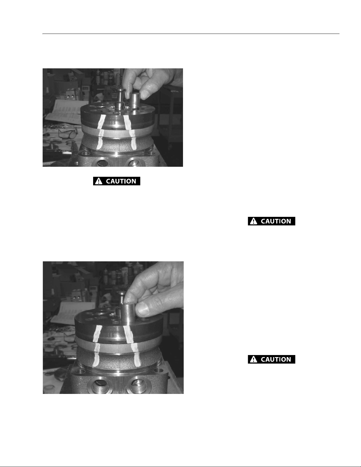
SECTION 3 - CHASSIS & TURNTABLE
4. Assemble six vanes, or as many vanes that will readily
assemble into the stator vane pockets.
EXCESSIVE FORCE USED TO PUSH THE ROTOR VANES INTO PLACE COULD
SHEAR OFF THE COATING APPLIED TO THE STATOR VANE POCKETS.
5. Grasp the output end of coupling shaft (12) with locking
pliers or other appropriate turning device and rotate
coupling shaft, drive link and rotor to seat the rotor and
the assembled vanes into stator, creating the necessary
clearance to assemble the seventh or full complement
of seven vanes. Assemble the seven vanes using minimum force.
Two Piece Stator Construction
A disassembled rotor set (8) that cannot be readily assembled
by hand and has a two piece stator can be assembled by the
following procedures.
1. Place stator half onto wear plate (9) with seal ring
(4) side down, after following motor assembly procedures 1 through 13. Be sure the seal ring is in place.
2. Align stator bolt holes with wear plate and
housing bolts and turn two alignment studs
finger tight into bolt holes approximately 180 degrees
apart to retain stator half and wear plate stationary.
3. Assemble rotor, counterbore down if applicable, into
stator half, and onto wear plate (9) with rotor splines
into mesh with drive link (10) splines.
NOTE: Use any marking you applied to rotor set components to
reassemble the components in their original relationship
to ensure ultimate wear life and performance.
4. Assemble six vanes, or as many vanes that will readily
assemble into the stator vane pockets.
EXCESSIVE FORCE USED TO PUSH THE ROTOR VANES INTO PLACE COULD
SHEAR OFF THE COATING APPLIED TO THE STATOR VANE POCKETS.
5. Grasp the output end of coupling shaft (12) with
locking pliers or other appropriate turning device and
rotate coupling shaft, drive link and rotor to seat the
rotor and the assembled vanes (8C) into stator half, creating the necessary clearance to assemble the seventh
or full complement of seven vanes. Assemble the seven
vanes using minimum force.
6. Place second stator half on a flat surface with seal ring
groove up. Apply a small amount of grease to a new seal
ring (4) and assemble it into stator half ring groove.
7. Assemble the second stator half over the two alignment
studs and rotor with seal ring side down onto the first
stator half aligning any timing marks applied for this
purpose.
IF THE STATOR HALF (8B) IS A DIFFERENT HEIGHT (THICKNESS) THAN STATOR
HALF (8D) THE STATOR VANES (8C) OR (8E)OF THE SAME LENGTH (HEIGHT) AS
THE STATOR HALF MUST BE REASSEMBLED IN THEIR RESPECTIVE STATOR
HALF FOR THE ROTOR SET TO FUNCTION PROPERLY.
6. Remove the two assembled bolts (1) if used to retain stator and wear plate.
Go to assembly procedure #15, to continue assembly.
3121259 – JLG Lift – 3-49

SECTION 3 - CHASSIS & TURNTABLE
TORQUE
8. Assemble six vanes, or as many vanes that will readily
assemble into the stator vane pockets.
9. Grasp the output end of coupling shaft (12)
with locking pliers or other appropriate turning device
and rotate coupling shaft, drive link and rotor to seat the
rotor and the assembled vanes into stator, creating the
necessary clearance to assemble the seventh or full
complement of seven vanes. Assemble the seven vanes
using minimum force.
Go to assembly procedure #15, to continue assembly.
Final Checks
1. Pressurize the motor with 100 p.s.i. dry air or nitrogen
and submerge in solvent to check for external leaks.
2. Check motor for rotation. Torque required to rotate coupling shaft should not be more than 50 ft. lbs. (68 N m)
3. Pressure port with "A" cast under it on housing (18) is for
clockwise coupling shaft rotation as viewed from the
output end of coupling shaft. Pressure port with "B" cast
under it is for counter clockwise coupling shaft rotation.
4. Use test stand if available, to check operation of the
motor.
3.11 SWING DRIVE
The swing drive assembly has five major components. They
are the housing, worm, worm gear, output pinion and gear /
pinion cap. The unit cannot be serviced while mounted on the
machine.
Removal
1. Remove the hardware securing the battery cover and
remove the battery cover.
2. Disconnect the negative terminal on the battery.
Installation
Refer to Figure 3-31., Swing Motor Removal and Installation.
1. Carefully insert the swing motor into the swing drive,
making sure the swing motor shaft key is aligned correctly.
2. Secure the swing motor to the swing drive assembly
with the retaining bolts. Apply threadlocker JLG P/N
0100019 to the threads of the retaining bolts and torque
to 85 ft.lbs. (115 Nm).
3. Connect the hydraulic lines running to the swing motor
as tagged during removal.
MAKE SURE THE EYEBOLTS HAVE A RATED WORK LOAD SUFFICIENT TO HANDLE THE LOAD OF THE UPPERSTRUCTURE OF THE MACHINE. THE UPPERSTRUCTURE WEIGHS APPROXIMATELY 7,000 LBS. (3175 KG).
4. Operate the swing function in both directions to ensure
proper operation. Inspect the hose connections for any
leakage.
3-50 – JLG Lift – 3121259

3. Install eyebolts as specified in Figure 3-33., Eyebolt for
Counterweight in the counterweight.
4. Securely strap the booms together to prevent any
movement during the lifting process.
SECTION 3 - CHASSIS & TURNTABLE
3121259 – JLG Lift – 3-51

SECTION 3 - CHASSIS & TURNTABLE
5. If equipped, remove the LP fuel tank on the side of the
frame. It may also be desirable to remove the tank
retaining brackets to gain additional clearance to work.
6. Remove the access covers on either side of the frame to
gain entry to the flow divider valve.
3-52 – JLG Lift – 3121259

SECTION 3 - CHASSIS & TURNTABLE
41
81
40
135
20
35
M20x2.5 Thread
Figure 3-33. Eyebolt for Counterweight
NOTE: All measurements shown are in mm.
7. Pull out the engine tray as far as it will go. Unbolt the
charge filter bracket so it can be moved aside for more
working area.
3121259 – JLG Lift – 3-53

SECTION 3 - CHASSIS & TURNTABLE
8. Loosen and remove all but a few of the bolts securing
the turntable to the swing bearing.
9. Place a drain pan under the flow divider valve to catch
any escaping hydraulic oil. Tag and disconnect the hoses
from the flow divider valve that go up through the turntable. Cap or plug all openings so no dirt enters the system.
12. Attach chains and slings to support the upperstructure.
Begin with the chain at the approximate lengths as
shown below and adjust as necessary to maintain the
turntable in a level position during lifiting.
13. Remove the remaining turntable bolts that were left in
place earlier in the procedure.
10. Remove the drive orientation and lockout switches so
they don’t get broken during the removal procedure.
14. Lift the turntable off of the bearing and place it out of
the way on adequate blocking.
11. Swing the engine tray back into position and secure it in
place with the retaining bolt.
3-54 – JLG Lift – 3121259

SECTION 3 - CHASSIS & TURNTABLE
5. Install several bearing bolts snuggly to secure the turntable’s position on the swing bearing assembly, but do
not torque them at this time and keep the lifting device
in place to support the weight of the turntable.
6. Coat the bearing bolts with JLG Threadlocker P/N
0100019 and install the remaining bolts securing the
turntable to the swing bearing. Tighten the bolts snugly
but do not torque them at this time. Remove the bolts
installed to secure the turntable’s position and apply
threadlocker to them. Reinstall them in the same manner as the other bolts.
7. Following the torque sequence diagram in Figure 3-37.,
Swing Bearing Torque Sequence, tighten the bolts to an
initial torque of 95 ft.lbs. (130 Nm). Next, following the
same sequence, tighten to a final torque of 133 ft.lbs.
(180 Nm).
15. Remove the bolts securing the bearing to the frame. It
may be necessary to disconnect more hoses on the flow
divider valve. If so, tag and disconnect all hoses and cap
or plug all openings to prevent dirt from entering the
hydraulic system.
NOTE: The swing bearing assembly weighs approximately 125
lbs. (56.6 kg).
16. Remove the bearing assembly from the frame.
Installation
NOTE: The swing bearing assembly weighs approximately 125
lbs. (56.6 kg).
1. Using an adequate lifting device, place the bearing
assembly onto the frame.
2. Install the bearing in the position shown in Figure 3-36.,
Bearing Placement. Coat the bearing bolts with JLG
Threadlocker P/N 0100019 and secure the bearing
assembly to the frame with the bolts. Following the
torque sequence diagram in Figure 3-37., Swing Bearing
Torque Sequence, tighten the bolts to an initial torque
of 95 ft.lbs. (130 Nm). Next, following the same
sequence, tighten to a final torque of 133 ft.lbs. (180
Nm).
8. Install the drive orientation and lockout switches.
9. Route the hydraulic hoses down through the turntable
and reconnect them as they were tagged during
removal.
10. Secure the charge filter bracket.
11. Install the access covers on the side of the frame.
12. If removed, install the LP tank retaining brackets and LP
fuel tank.
13. Remove the lifting device from the machine.
14. Remove any straps that had been on the boom to pre-
vent movement of the boom sections.
15. Remove the eyebolts from the counterweight.
16. Connect the negative terminal on the battery.
17. Install the battery cover.
18. Push the engine tray back into place and secure it.
19. Start the machine and run it through several operating
cycles. Swing the machine in both directions.
20. Check for any leaks and that all functions are operating
properly. Top off the hydraulic oil level if necessary.
3. If any hydraulic hoses were disconnected to remove the
swing bearing assembly, reconnect them as tagged during removal.
NOTE: The turntable assembly weighs approximately 7000 lbs.
(3175 kg).
4. Using an adequate lifting device, lift the turntable
assembly from the blocking it is resting on and lower it
down onto the swing bearing assembly. Refer to the
removal instructions for chain placement.
3121259 – JLG Lift – 3-55

SECTION 3 - CHASSIS & TURNTABLE
.0015" Feeler Gauge
Figure 3-34. Swing Bearing Feeler Gauge Check
SWING
BEARING
FRAME REF.
TURNTABLE REF.
MEASURING
POINT
Figure 3-35. Swing Bearing Tolerance Measuring Point
Turntable Bearing Mounting Bolt Condition Check
NOTE: This check is designed to replace the existing bearing bolt
torque checks on JLG Lifts in service. This check must be
performed after the first 50 hours of machine operation
and every 600 hours of machine operation thereafter. If
during this check any bolts are found to be missing or
loose, replace missing or loose bolts with new bolts and
torque to the value specified in the torque chart, after lubricating the bolt threads with loctite #271. After replacing
and retorquing bolt or bolts recheck all existing bolts for
looseness.
Check the frame to bearing. Attach bolts as follows:
1. Elevate the fully retracted boom to 70 degrees (full elevation).
2. At the positions indicated on the figure titled Swing
Bearing Tolerance Boom Placement. Try and insert the
0.0015" feeler gauge between the bolt head and hardened washer at the arrow indicated position.
3. Assure that the 0.0015" feeler gauge will not penetrate
under the bolt head to the bolt shank.
4. Swing the turntable 90 degrees, and check some
selected bolts at the new position.
5. Continue rotating the turntable at 90 degrees intervals
until a sampling of bolts have been checked in all quadrants.
Check the turntable to bearing. Attach bolts as follows:
1. Elevate the fully retracted boom to 70 degrees (full elevation).
2. At the positions indicated in the figure below, try and
insert the 0.0015" feeler gauge between the bolt head
and hardened washer at the arrow indicated position.
Wear Tolerance
1. With the boom positioned over the side of the machine,
the Upper Boom horizontal with telescope fully
extended and Mid/Lower Boom stowed, using a magnetic base dial indicator, measure and record the distance between the swing bearing and turntable.
2. At the same point, with the boom positioned over the
side of the machine, the Upper Boom fully elevated and
the Mid/Lower Boom fully elevated, using a magnetic
base dial indicator, measure and record the distance
between the swing bearing and turntable.
3. If a difference greater than 0.057 in. (1.40 mm) is determined, the swing bearing should be replaced.
4. If a difference less than 0.057 in. (1.40 mm) is determined, and any of the following conditions exist, the
bearing should be removed.
a. Metal particles in the grease.
b. Increased drive power.
c. Noise.
d. Rough rotation.
5. If bearing inspection shows no defects, reassemble
bearing and return to service.
Swing Bearing Torque Value
Install bolts with JLG Threadlocker P/N 0100019; Torque to 133
ft.lbs. (180 Nm).
3. Lower the boom to horizontal and fully extend the
boom.
4. At the position indicated on Figure 2-30. try and insert
the 0.0015" feeler gauge between the bolt head and
hardened washer at the arrow indicated position.
3-56 – JLG Lift – 3121259

SECTION 3 - CHASSIS & TURNTABLE
(90°)
POSITION POINT OF MINIMAL BACKLASH
MARKED WITH AN "X"
AND ALSO BLUE PAINT,
TO THE FRAME IN THIS POSITION.90°
POSITION BEARING BODY TO
TURNTABLE AS SHOWN
Figure 3-36. Bearing Placement
3121259 – JLG Lift – 3-57

SECTION 3 - CHASSIS & TURNTABLE
S
Figure 3-37. Swing Bearing Torque Sequence
Disassembly
The servicing of these units requires a press, a 5/16" 12 point
socket, a 7/16" socket, a ¾" socket, torque wrench (80 lb-ft),
steel hammer, soft face hammer, bearing puller (external and
internal), large flat blade screw driver. Also needed are a shim
and seal kit (available from the JLG Parts Department), ¾" steel
rod at least 10" long, LocTite #515, Mobil SHC 007 grease,
Mobil SHC 460 grease, LocTite 242/243 for bolts, and any
replacement parts.
1. Remove the swing bearing assembly from the machine.
2. To remove the slew ring (14), remove two 1/4" (5) bolts
and washers (1) that hold the slew ring to the housing.
3. Remove four #6 machine screws (13) that are located on
the cover plate (19) immediately in front of the Pinion
(21).
4. Remove eight 5/16" 12 point cap screws (4) from gear/
pinion cap (18). Pry cap from housing. Cover plate (19)
will come off with cap. Note where sealant is on Cover
and plate so when assembling can put sealant in same
place. Note number and color of shims (26) between cap
and housing. Remove 6 small screws (13) from cover
plate. Pry cover plate (19) from cap (18) and discard
cover plate. Note number and color of shims between
cover plate and cap.
5. Remove Pinion and Gear assembly (15, 16, 17, 21, 23, 24,
and 31) from housing. These lift directly upward from
the housing.
6. Disassemble pinion and gear assembly using a press.
Support worm gear (31) on press with pinion (21) down
allowing room for pinion to be pressed out of gear. Press
pinion out of bearing (17) spacer (24) and worm gear
(31) Pressing on end of pinion. Remove face seal (23)
from face of worm gear (31). Note how the seal is assembled.
3-58 – JLG Lift – 3121259
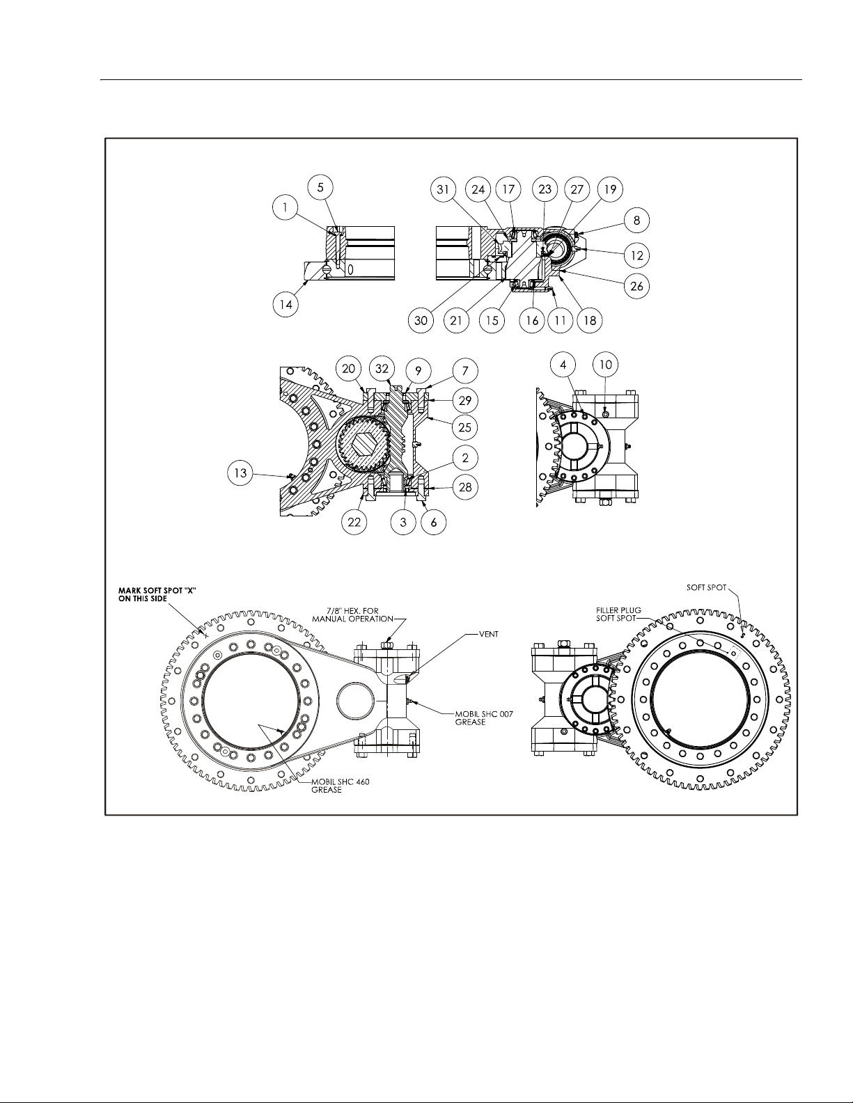
SECTION 3 - CHASSIS & TURNTABLE
1. Washer
2. Bearing
3. Oil Seal
4. Capscrew
5. Bolt
6. Bolt
7. Bolt
8. Pressure Vent
9. Oil Seal
10. Pipe Plug
11. Grease Fitting
12. Grease Fitting
13. Grease Fitting
14. Slew Ring
15. Bearing
16. Grease Ring
17. Bearing
18. Gear Cap
19. Cover Plate
20. Worm Cap
21. Output Pinion
22. Motor Adapter
23. Face Seal
24. Washer Spacer
25. Housing
26. Cap Shim
27. Cover Shim
28. Gasket
29. Gasket
30. Screw
31. Worm Gear
32. Worm
Figure 3-38. Swing Gear Assembly
3121259 – JLG Lift – 3-59

SECTION 3 - CHASSIS & TURNTABLE
7. Remove bearing (15) and Nilos Ring (16) from pinion
(21) using external bearing puller or press.
8. Remove motor and motor adapter (22) and shims (28).
9. Remove ¾" bolts (7) from Worm Cap (20) using ¾"
socket. Remove shim (29) and seal (9) and discard.
10. Remove worm (32) from housing (25) by pushing worm
from motor end using steel rod and hammer. Bearing
cup (3) on hex end of worm will be forced out of housing. Once the bearing cup (2) has come out of housing
use soft hammer to tap worm on hex end to remove
other bearing cup (2) out the other end of housing.
11. Remove both bearings (2) from worm (32) from worm
using external bearing puller or press.
12. Bearing cup (17) can be removed from housing (25) by
lifting out (this is not a press fit just a close slip fit).
13. Bearing cup (15) can be removed from cap (18) using
small pry bar. Or by welding a small bead of weld on
internal diameter of cup, this is a press fit.
Assembly
1. Press bearing cup (15) into cap (18).
2. Place bearing cup (17) into housing (25).
7. Install bearing (2) on bore end of worm (32) only. This is
almost a slip fit, may have to be lightly tapped with soft
hammer.
8. Install worm (32) into housing (25), hex end first.
9. On bore end of worm, install bearing cup (2) into worm
bore of housing. Also on bore end of worm (32) install
motor adapter (22) and 1 shim (28 yellow) to housing
using ¾-13 x 1" bolts (6) and sealant. Torque to 75 ft-lbs.
(3.1 Nm) (these bolts will be replaced with motor bolts
when motor is mounted).
10. Install bearing cone (2) on hex end of worm (32). Place
bearing cup (2) over bearing and lightly tap cup into
bore using soft hammer.
11. Install worm cap (20) using proper shims (29) to achieve
0.000 to 0.001" (0.0000 to 0.0254 mm) end play. Apply
LocTite 242 to end of ¾-13 x 1.25" grade 5 bolts (7) and
LocTite #515 sealant to shims. Torque bolts to 75 ft-lbs.
(3.1 Nm).
12. Place pinion/gear assembly into housing so gear teeth
mesh with worm gear teeth. May have to turn worm or
gear set by hand to achieve this.
13. Apply LocTite #515 to surfaces of housing where cap
assembly will touch. This includes the vertical surfaces.
3. Put face seal (23) on to hub of worm gear (31) with flap
of seal pointing away from gear.
4. Place worm gear (31) on press with face seal up and
press pinion (21) into worm gear. Place Nilos Ring (16)
on to pinion so that cup shape is up and press bearing
(15) on to pinion tight to Nilos Ring.
5. Turn assembly over and place spacer (24) on pinion
against gear hub so that large chamfer on I.D. of spacer
is against Bronze gear. Press Bearing (17) on to pinion
tight to spacer and gear.
6. Place pinion/gear assembly into housing. Place gear cap
(18) and shims (26) over gear/pinion assembly to
achieve a slight preload on pinion bearings. Remove cap
and shims and set shims aside. Install new cover plate
(19) on to cap using 6 screws (30) and shims (26) equal
to or close to equal to total thickness of shims just set
aside. Apply sealant (LocTite #515) to both sides of each
of these shims and tighten screws take care not to twist
these screws off. Clean extra sealant from surfaces of
cover plate. Apply a small amount of grease to this flap.
Set this assembly to the side.
14. Place gear cap assembly and shims set aside in step 6,
over pinion assembly.
15. Apply LocTite 242 to end of eight 5/16" 12 point screws
(4) and torque to 20 ft-lbs. (0.84 Nm)
16. Install 4 small screws (30) through cover plate (18) and
into housing (25) tighten screws take care not the twist
these screws off.
17. Install seal (9) in worm cap at hex end of worm.
18. Install slew ring (14) using two 1/4" bolts (5) and washer
(1). Adjust backlash with pinion to 0.008/0.012" (0.203/
0.305 mm) and torque bolts to 10 ft-lbs. (0.42 Nm).
19. Fill unit with SHC 007 grease and grease pinion bearing
(15) thru fitting (11) with Mobil SHC 460 grease.
3-60 – JLG Lift – 3121259
 Loading...