


Service & Maintenance Manual
Model
330CRT
400CRT
3121111
August 18, 2004


INTRODUCTION - MAINTENANCE SAFETY PRECAUTIONS
SECTION A. INTRODUCTION - MAINTENANCE SAFETY
PRECAUTIONS
A.A GENERAL
This section contains the general safety precautions
which must be observed during maintenance of the
aerial platform. It is of utmost importance that maintenance personnel pay strict attention to these warnings and precautions to avoid possible injury to
themselves or others, or damage to the equipment.
A maintenance program must be followed to ensure
that the machine is safe to operate.
MODIFICATION OF THE MACHINE WITHOUT CERTIFICATION BY A RESPONSIBLE AUTHORITY THAT THE
MACHINE IS AT LEAST AS SAFE AS ORIGINALLY
MANUFACTURED, IS A SAFETY VIOLATION.
The specific precautions to be observed during
maintenance are inserted at the appropriate point in
the manual. These precautions are, for the most
part, those that apply when servicing hydraulic and
larger machine component parts.
Your safety, and that of others, is the first consideration when engaging in the maintenance of equipment. Always be conscious of weight. Never attempt
to move heavy parts without the aid of a mechanical
device. Do not allow heavy objects to rest in an
unstable position. When raising a portion of the
equipment, ensure that adequate support is provided.
SINCE THE MACHINE MANUFACTURER HAS NO
DIRECT CONTROL OVER THE FIELD INSPECTION
AND MAINTENANCE, SAFETY IN THIS AREA RESPONSIBILITY OF THE OWNER/OPERATOR.
A.B HYDRAULIC SYSTEM SAFETY
It should be noted that the machines hydraulic systems operate at extremely high potentially dangerous pressures. Every effort should be made to
relieve any system pressure prior to disconnecting
or removing any portion of the system.
Relieve system pressure by cycling the applicable
control several times with the engine stopped and
ignition on, to direct any line pressure back into the
reservoir. Pressure feed lines to system components
can then be disconnected with minimal fluid loss.
A.C MAINTENANCE
FAILURE TO COMPLY WITH SAFETY PRECAUTIONS
LISTED IN THIS SECTION MAY RESULT IN MACHINE
DAMAGE, PERSONNEL INJURY OR DEATH AND IS A
SAFETY VIOLATION.
• NO SMOKING IS MANDATORY. NEVER REFUEL DURING ELECTRICAL STORMS. ENSURE THAT FUEL CAP
IS CLOSED AND SECURE AT ALL OTHER TIMES.
• REMOVE ALL RINGS, WATCHES AND JEWELRY
WHEN PERFORMING ANY MAINTENANCE.
• DO NOT WEAR LONG HAIR UNRESTRAINED, OR
LOOSE-FITTING CLOTHING AND NECKTIES WHICH
ARE APT TO BECOME CAUGHT ON OR ENTANGLED
IN EQUIPMENT.
• OBSERVE AND OBEY ALL WARNINGS AND CAUTIONS ON MACHINE AND IN SERVICE MANUAL.
• KEEP OIL, GREASE, WATER, ETC. WIPED FROM
STANDING SURFACES AND HAND HOLDS.
• USE CAUTION WHEN CHECKING A HOT, PRESSURIZED COOLANT SYSTEM.
• NEVER WORK UNDER AN ELEVATED BOOM UNTIL
BOOM HAS BEEN SAFELY RESTRAINED FROM ANY
MOVEMENT BY BL OCKING OR OV ERHEAD SL ING,
OR BOOM SAFETY PROP HAS BEEN ENGAGED.
• BEFORE MAKING ADJUSTMENTS, LUBRICATING OR
PERFORMING ANY OTHER MAINTENANCE, SHUT
OFF ALL POWER CONTROLS.
• BATTERY SHOULD ALWAYS BE DISCONNECTED
DURING REPLACEMENT OF ELECTRICAL COMPONENTS.
• KEEP ALL SUPPORT EQUIPMENT AND ATTACHMENTS STOWED IN THEIR PROPER PLACE.
• USE ONLY APPROVED, NONFLA MMABLE CLEANING
SOLVENTS.
3121111 – JLG Lift – a

INTRODUCTION - MAINTENANCE SAFETY PRECAUTIONS
REVISON LOG
Original Issue - April 11, 2000
Revised - December 12, 2000
Revised - September 28, 2001
Revised - October 18, 2002
Revised - April 6, 2004
Revised - August 18, 2004
b – JLG Lift – 3121111

TABLE OF CONTENTS
TABLE OF CONTENTS
SUBJECT - SECTION, PARAGRAPH PAGE NO.
SECTION A - INTRODUCTION - MAINTENANCE SAFETY PRECAUTIONS
A.A General . . . . . . . . . . . . . . . . . . . . . . . . . . . . . . . . . . . . . . . . . . . . . . . . . . . . . . . . . . . . . . . . . . . . . . 1-a
A.B Hydraulic System Safety . . . . . . . . . . . . . . . . . . . . . . . . . . . . . . . . . . . . . . . . . . . . . . . . . . . . . . . . 1-a
A.C Maintenance . . . . . . . . . . . . . . . . . . . . . . . . . . . . . . . . . . . . . . . . . . . . . . . . . . . . . . . . . . . . . . . . . . 1-a
SECTION 1 - SPECIFICATIONS
1.1 Capacities . . . . . . . . . . . . . . . . . . . . . . . . . . . . . . . . . . . . . . . . . . . . . . . . . . . . . . . . . . . . . . . . . . . . 1-1
1.2 Component Data . . . . . . . . . . . . . . . . . . . . . . . . . . . . . . . . . . . . . . . . . . . . . . . . . . . . . . . . . . . . . . 1-1
1.3 Performance Data. . . . . . . . . . . . . . . . . . . . . . . . . . . . . . . . . . . . . . . . . . . . . . . . . . . . . . . . . . . . . . 1-1
1.4 Torque Requirements. . . . . . . . . . . . . . . . . . . . . . . . . . . . . . . . . . . . . . . . . . . . . . . . . . . . . . . . . . . 1-2
1.5 Lubrication . . . . . . . . . . . . . . . . . . . . . . . . . . . . . . . . . . . . . . . . . . . . . . . . . . . . . . . . . . . . . . . . . . . 1-2
1.6 Pressure Settings . . . . . . . . . . . . . . . . . . . . . . . . . . . . . . . . . . . . . . . . . . . . . . . . . . . . . . . . . . . . . . 1-5
1.7 Serial Number Locations . . . . . . . . . . . . . . . . . . . . . . . . . . . . . . . . . . . . . . . . . . . . . . . . . . . . . . . . 1-5
1.8 Limit Switches. . . . . . . . . . . . . . . . . . . . . . . . . . . . . . . . . . . . . . . . . . . . . . . . . . . . . . . . . . . . . . . . . 1-5
1.9 Cylinder Specifications. . . . . . . . . . . . . . . . . . . . . . . . . . . . . . . . . . . . . . . . . . . . . . . . . . . . . . . . . . 1-6
1.10 Major Component Weights. . . . . . . . . . . . . . . . . . . . . . . . . . . . . . . . . . . . . . . . . . . . . . . . . . . . . . . 1-6
1.11 Critical Stability Weights . . . . . . . . . . . . . . . . . . . . . . . . . . . . . . . . . . . . . . . . . . . . . . . . . . . . . . . . . 1-6
SECTION 2 - PROCEDURES
2.1 General . . . . . . . . . . . . . . . . . . . . . . . . . . . . . . . . . . . . . . . . . . . . . . . . . . . . . . . . . . . . . . . . . . . . . . 2-1
2.2 Servicing and Maintenance Guidelines . . . . . . . . . . . . . . . . . . . . . . . . . . . . . . . . . . . . . . . . . . . . .2-1
2.3 Lubrication Information. . . . . . . . . . . . . . . . . . . . . . . . . . . . . . . . . . . . . . . . . . . . . . . . . . . . . . . . . . 2-2
2.4 Cylinders - Theory of Operation . . . . . . . . . . . . . . . . . . . . . . . . . . . . . . . . . . . . . . . . . . . . . . . . . . . 2-3
2.5 Valves - Theory of Operation . . . . . . . . . . . . . . . . . . . . . . . . . . . . . . . . . . . . . . . . . . . . . . . . . . . . . 2-3
2.6 Component Functional Description . . . . . . . . . . . . . . . . . . . . . . . . . . . . . . . . . . . . . . . . . . . . . . . . 2-4
2.7 Wear Pads. . . . . . . . . . . . . . . . . . . . . . . . . . . . . . . . . . . . . . . . . . . . . . . . . . . . . . . . . . . . . . . . . . . . 2-4
2.8 Cylinder Checking Procedures . . . . . . . . . . . . . . . . . . . . . . . . . . . . . . . . . . . . . . . . . . . . . . . . . . . 2-4
2.9 Lift Cylinder Removal and Installation . . . . . . . . . . . . . . . . . . . . . . . . . . . . . . . . . . . . . . . . . . . . . . 2-5
2.10 Lift Cylinder Repair . . . . . . . . . . . . . . . . . . . . . . . . . . . . . . . . . . . . . . . . . . . . . . . . . . . . . . . . . . . . . 2-9
2.11 Steer Cylinder Repair . . . . . . . . . . . . . . . . . . . . . . . . . . . . . . . . . . . . . . . . . . . . . . . . . . . . . . . . . . . 2-14
2.12 Oscillation Cylinder Bleeding . . . . . . . . . . . . . . . . . . . . . . . . . . . . . . . . . . . . . . . . . . . . . . . . . . . . . 2-16
2.13 Magnetic Speed Pickup Cleaning Procedure . . . . . . . . . . . . . . . . . . . . . . . . . . . . . . . . . . . . . . . . 2-16
2.14 Pressure Setting Procedures . . . . . . . . . . . . . . . . . . . . . . . . . . . . . . . . . . . . . . . . . . . . . . . . . . . . . 2-17
2.15 Limit Switch Adjustment . . . . . . . . . . . . . . . . . . . . . . . . . . . . . . . . . . . . . . . . . . . . . . . . . . . . . . . . . 2-18
2.16 Automatic Choke - Field Adjustment (DF-750) . . . . . . . . . . . . . . . . . . . . . . . . . . . . . . . . . . . . . . . 2-18
2.17 Electronic Control System . . . . . . . . . . . . . . . . . . . . . . . . . . . . . . . . . . . . . . . . . . . . . . . . . . . . . . . 2-19
2.18 Flash Codes and Descriptions . . . . . . . . . . . . . . . . . . . . . . . . . . . . . . . . . . . . . . . . . . . . . . . . . . . . 2-21
2.19 Preventive Maintenance and Inspection Schedule . . . . . . . . . . . . . . . . . . . . . . . . . . . . . . . . . . . . 2-27
SECTION 3 - TROUBLESHOOTING
3.1 General . . . . . . . . . . . . . . . . . . . . . . . . . . . . . . . . . . . . . . . . . . . . . . . . . . . . . . . . . . . . . . . . . . . . . . 3-1
3.2 Troubleshooting Information . . . . . . . . . . . . . . . . . . . . . . . . . . . . . . . . . . . . . . . . . . . . . . . . . . . . . 3-1
3.3 Hydraulic Circuit Checks . . . . . . . . . . . . . . . . . . . . . . . . . . . . . . . . . . . . . . . . . . . . . . . . . . . . . . . . 3-1
3121111 – JLG Lift – i

TABLE OF CONTENTS
LIST OF FIGURES
FIGURE NO. TITLE PAGE NO.
1-1. Lubrication Diagram . . . . . . . . . . . . . . . . . . . . . . . . . . . . . . . . . . . . . . . . . . . . . . . . . . . . . . . . . . . . 1-3
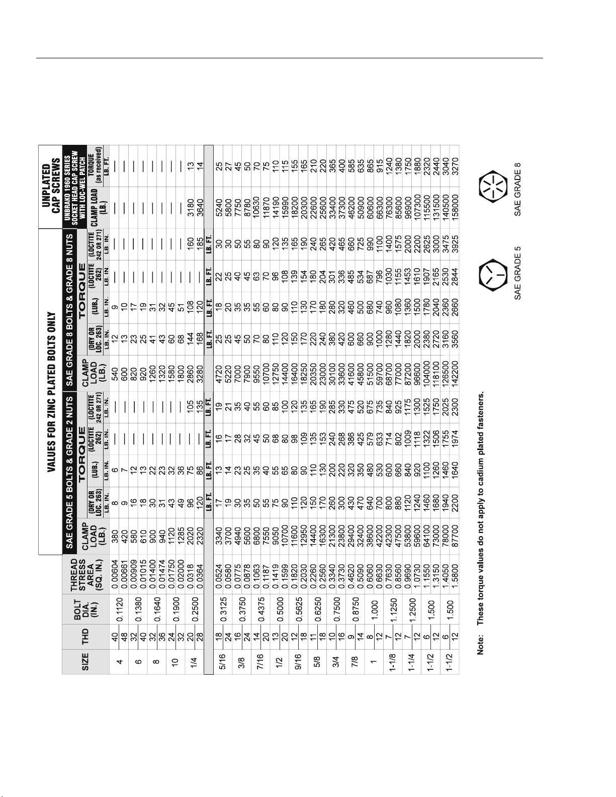
1-1. Torque Chart . . . . . . . . . . . . . . . . . . . . . . . . . . . . . . . . . . . . . . . . . . . . . . . . . . . . . . . . . . . . . . . . . .1-4
1-2. Serial Number Location. . . . . . . . . . . . . . . . . . . . . . . . . . . . . . . . . . . . . . . . . . . . . . . . . . . . . . . . . .1-5
2-1. Arms and Platform Positioning and Support, Cylinder Repair. . . . . . . . . . . . . . . . . . . . . . . . . . . .2-6
2-2. 330CRT Lift Cylinder . . . . . . . . . . . . . . . . . . . . . . . . . . . . . . . . . . . . . . . . . . . . . . . . . . . . . . . . . . . . 2-7
2-3. 400CRT LIft Cylinder . . . . . . . . . . . . . . . . . . . . . . . . . . . . . . . . . . . . . . . . . . . . . . . . . . . . . . . . . . . .2-8
2-4. Cylinder Barrel Support. . . . . . . . . . . . . . . . . . . . . . . . . . . . . . . . . . . . . . . . . . . . . . . . . . . . . . . . . .2-9
2-5. Capscrew Removal . . . . . . . . . . . . . . . . . . . . . . . . . . . . . . . . . . . . . . . . . . . . . . . . . . . . . . . . . . . . .2-9
2-6. Cylinder Rod Support . . . . . . . . . . . . . . . . . . . . . . . . . . . . . . . . . . . . . . . . . . . . . . . . . . . . . . . . . . . 2-9
2-7. Tapered Bushing Removal . . . . . . . . . . . . . . . . . . . . . . . . . . . . . . . . . . . . . . . . . . . . . . . . . . . . . . .2-10
2-8. Rod Seal Installation . . . . . . . . . . . . . . . . . . . . . . . . . . . . . . . . . . . . . . . . . . . . . . . . . . . . . . . . . . . .2-11
2-9. Wiper Seal Installation. . . . . . . . . . . . . . . . . . . . . . . . . . . . . . . . . . . . . . . . . . . . . . . . . . . . . . . . . . .2-11
2-10. Installation of Head Seal Kit . . . . . . . . . . . . . . . . . . . . . . . . . . . . . . . . . . . . . . . . . . . . . . . . . . . . . .2-11
2-11. Piston Seal Kit Installation . . . . . . . . . . . . . . . . . . . . . . . . . . . . . . . . . . . . . . . . . . . . . . . . . . . . . . . . 2-12
2-12. Tapered Bushing Installation . . . . . . . . . . . . . . . . . . . . . . . . . . . . . . . . . . . . . . . . . . . . . . . . . . . . .2-12
2-13. Seating the Tapered Bearing . . . . . . . . . . . . . . . . . . . . . . . . . . . . . . . . . . . . . . . . . . . . . . . . . . . . .2-12
2-14. Poly-Pak Piston Seal Installation. . . . . . . . . . . . . . . . . . . . . . . . . . . . . . . . . . . . . . . . . . . . . . . . . . .2-13
2-15. Rod Assembly Installation. . . . . . . . . . . . . . . . . . . . . . . . . . . . . . . . . . . . . . . . . . . . . . . . . . . . . . . . 2-13
2-16. Steer Cylinder Assembly . . . . . . . . . . . . . . . . . . . . . . . . . . . . . . . . . . . . . . . . . . . . . . . . . . . . . . . . . 2-14
2-17. Magnetic Speed Pickup . . . . . . . . . . . . . . . . . . . . . . . . . . . . . . . . . . . . . . . . . . . . . . . . . . . . . . . . .2-16
2-18. Magnetic Speed Pickup Removal. . . . . . . . . . . . . . . . . . . . . . . . . . . . . . . . . . . . . . . . . . . . . . . . . . 2-16
2-19. Valve Components . . . . . . . . . . . . . . . . . . . . . . . . . . . . . . . . . . . . . . . . . . . . . . . . . . . . . . . . . . . . . 2-17
2-20. Automatic Choke Adjustment (DF-750) . . . . . . . . . . . . . . . . . . . . . . . . . . . . . . . . . . . . . . . . . . . . . 2-18
2-21. Analyzer Flow Chart - Sheet 1 of 2 . . . . . . . . . . . . . . . . . . . . . . . . . . . . . . . . . . . . . . . . . . . . . . . . .2-23
2-22. Analyzer Flow Chart - Sheet 2 of 2 . . . . . . . . . . . . . . . . . . . . . . . . . . . . . . . . . . . . . . . . . . . . . . . . .2-24
3-1. Electrical Schematic - Sheet 1 of 2 . . . . . . . . . . . . . . . . . . . . . . . . . . . . . . . . . . . . . . . . . . . . . . . . .3-10
3-2. Electrical Schematic - Sheet 2 of 2 . . . . . . . . . . . . . . . . . . . . . . . . . . . . . . . . . . . . . . . . . . . . . . . . . 3-11
3-3. Hydraulic Schematic - Sheet 1 of 2. . . . . . . . . . . . . . . . . . . . . . . . . . . . . . . . . . . . . . . . . . . . . . . . .3-12
3-4. Hydraulic Schematic - Sheet 2 of 2. . . . . . . . . . . . . . . . . . . . . . . . . . . . . . . . . . . . . . . . . . . . . . . . .3-13
ii – JLG Lift – 3121111

TABLE OF CONTENTS
LIST OF TABLES
TABLE NO. TITLE PAGE NO.
1-1 Hydraulic Oil . . . . . . . . . . . . . . . . . . . . . . . . . . . . . . . . . . . . . . . . . . . . . . . . . . . . . . . . . . . . . . . . . . 1-2
1-2 Lubrication Specifications . . . . . . . . . . . . . . . . . . . . . . . . . . . . . . . . . . . . . . . . . . . . . . . . . . . . . . . 1-2
1-3 Lubrication Chart . . . . . . . . . . . . . . . . . . . . . . . . . . . . . . . . . . . . . . . . . . . . . . . . . . . . . . . . . . . . . . 1-3
1-4 Cylinder Specifications. . . . . . . . . . . . . . . . . . . . . . . . . . . . . . . . . . . . . . . . . . . . . . . . . . . . . . . . . . 1-6
1-5 Major Component Weights. . . . . . . . . . . . . . . . . . . . . . . . . . . . . . . . . . . . . . . . . . . . . . . . . . . . . . . 1-6
1-6 Critical Stability Weights. . . . . . . . . . . . . . . . . . . . . . . . . . . . . . . . . . . . . . . . . . . . . . . . . . . . . . . . . 1-6
2-1 Cylinder Component Torque . . . . . . . . . . . . . . . . . . . . . . . . . . . . . . . . . . . . . . . . . . . . . . . . . . . . . 2-13
2-2 Holding Valve Torque Specifications . . . . . . . . . . . . . . . . . . . . . . . . . . . . . . . . . . . . . . . . . . . . . . . 2-13
2-3 Help Messages and Flash Codes . . . . . . . . . . . . . . . . . . . . . . . . . . . . . . . . . . . . . . . . . . . . . . . . . 2-21
2-4 Machine Model Adjustment . . . . . . . . . . . . . . . . . . . . . . . . . . . . . . . . . . . . . . . . . . . . . . . . . . . . . . 2-25
2-5 Machine Configuration Programming Information. . . . . . . . . . . . . . . . . . . . . . . . . . . . . . . . . . . . . 2-26
2-6 Preventive Maintenance and Safety Inspection. . . . . . . . . . . . . . . . . . . . . . . . . . . . . . . . . . . . . . . 2-28
3-1 Elevation System Troubleshooting. . . . . . . . . . . . . . . . . . . . . . . . . . . . . . . . . . . . . . . . . . . . . . . . . 3-2
3-2 Chassis Troubleshooting . . . . . . . . . . . . . . . . . . . . . . . . . . . . . . . . . . . . . . . . . . . . . . . . . . . . . . . . 3-4
3-3 Hydraulic System Troubleshooting . . . . . . . . . . . . . . . . . . . . . . . . . . . . . . . . . . . . . . . . . . . . . . . . 3-7
3-4 Electrical System Troubleshooting. . . . . . . . . . . . . . . . . . . . . . . . . . . . . . . . . . . . . . . . . . . . . . . . . 3-8
3121111 – JLG Lift – iii

TABLE OF CONTENTS
iv – JLG Lift – 3121111

SECTION 1 - SPECIFICATIONS
SECTION 1. SPECIFICATIONS
1.1 CAPACITIES
Hydraulic Oil Tank
Approximately 16 U.S. gallons (60.6 liters) w/15% air
space.
Hydraulic System (Including Tank)
Approximately 20 U.S. gallons (75.7 liters)
Fuel Tank
Approximately 13 U.S. gallons (48.8 liters)
Engine Crankcase
Gasoline Engine
3.4 quarts (3.2 liters) w/filter
2.9 quarts (2.7 liters) w/o filter
Diesel Engine
5.4 quarts (5.1 liters) w/filter
4.9 quarts (4.6 liters) w/o filter
Coolant Capacity
Diesel Engine
Manufacturer - Kubota 1105
Low RPM - 1500
High RPM - 3000
Alternator - 40 Amp
Fuel Consumption
Low RPM - 0.93 gph (3.5 lph)
High RPM - 1.7 gph (6.6 lph)
Horsepower - 28 @ 3000 RPM
Drive/Steer System
Toe-In - Adjust to 1/2 inch (12.7 mm) overall
Drive Motor Displacement- 400 cc
Drive Brake - Spring applied, hydraulic release, release
pressure - 300 psi (20.7 bar) max.
Hydraulic Filter - Full flow paper (Cartridge type)
10 Microns Nominal
Tires
Standard 30.4 x 10 loader pneumatic or foam filled
3.5 U.S. gallons (13.2 liters)
1.2 COMPONENT DATA
Gasoline Engine
Manufacturer - Kubota 750 Dual Fuel
Displacement - 750 cc
Low RPM - 2200
High RPM - 3600
Alternator - 40 Amp external
Battery - 85 Amphour, 700 cold cranking amps @ 0° F
Fuel Consumption
Low RPM - 1.3 gph (4.9 lph)
High RPM - 2.4 gph (9 lph)
Horsepower - 24.5 @ 3600 RPM
NOTE: Inflate pneumatic tire to 55 psi (3.8 bar)
1.3 PERFORMANCE DATA
Travel Speed
High drive - 3.5 m.p.h.
Gradeability
35%
Turning Radius (Inside)
7 ft. (2 m)
Lift Speed
L
Table 1-1. Lift Speeds
Model Lift Up (Sec) Lift Down (Sec)
330CRT - DF 26.5 - 28.5 43 - 48
330CRT - Diesel 33 - 35 43 - 48
400CRT - DF 39 - 43 49 - 51
400CRT - Diesel 43 - 47 49 - 51
3121111 – JLG Lift – 1-1

SECTION 1 - SPECIFICATIONS
Platform Capacity - Fixed Platform
330CRT - 1,000 lb. (455 kg)
400 CRT - 800 lb. (365 kg)
Platform Extension Capacity
All Models - 250 lb (120 kg)
Machine Weight
330CRT - Approx. 9,320 lb. (4,228 kg)
440CRT - Approx. 10,070 lb. (4,568 kg)
Machine Height (Fully Extended)
330 CRT - 33 ft. (10 m)
400 CRT - 40 ft. (12 m)
Machine Platform Height (Platform Lowered)
330 CRT - 66.5 in. (1.7 m)
400 CRT - 68.25 in. (1.7 m)
Machine Length
10 ft. 2 in. (3 m)
Machine Width
69 in. (1.8 m)
1.5 LUBRICATION
Ta b l e 1-2. Hydraulic Oil
HYDRAULIC SYSTEM OPERATING
TEMPERATURE RANGE
0 to +23 degrees F
(-18 to -5 degrees C )
0 to +210 degrees F
(-18 to +100 degrees C)
+50 to +210 degrees F
(+10 to +100 degrees C)
NOTE: Hydraulic oils must have anti-wear qualities at least
to API Service Classification GL-3, and sufficient
chemical stability for mobile hydraulic system service. JLG Industries recommends Mobilfluid 424
hydraulic oil, which has an SAE viscosity index
of152.
NOTE: Aside from JLG recommendations, it is not advisable
to mix oils of different brands or types, as they may
not contain the same required additives or be of
comparable viscosities. If use of hydraulic oil other
than Mobilfluid 424 is desired, contact JLG Industries for proper recommendations.
SAE VISCOSITY GRADE
10W
10W-20,10W-30
20W-20
1.4 TORQUE REQUIREMENTS
All wheel lugs must be torqued at 105 ft lb (142 ft lb) every
50 hours.
Lubrication Specifications
Table 1-3. Lubrication Specifications
KEY SPECIFICATIONS
MPG Multipurpose Grease having a minimum dripping
point of 350 degrees F. Excellent water resistance
and adhesive qualiti es, and being of extreme pres-
sure type. (Timken OK 40 pounds minimum.)
EPGL Extreme Pressure Gear Lube (oi l) meeting API ser-
vice classifica tion GL-5 or MIL-Spec MIL-L-2105.
EO Engine (crankcase) Oil. Gas - API SF/SG class, MIL-
L-2104. Diesel - API CC/CD class, MIL-L-2104B/
MIL-L-2104C.
HO Hydraulic Oil. A PI service classification GL-3, e .g.
Mobil 424.
1-2 – JLG Lift – 3121111

SECTION 1 - SPECIFICATIONS
4 Extends from
front of machine
Note:
500 Hrs. = 3 months
1000 Hrs. = 6 months
2000 Hrs. = 1 year
4000 Hrs. = 2 years
1
Figure 1-1. Lubrication Diagram
Table 1-4. Lubrication Chart
2
3
INDEX
NO
1 Hydraulic Oil Res ervoir Fill Cap/Drain Pl ug HO - Check HO Le vel
2 Hydraulic Filter Element N/A Initial Change - 50 H ours 250
3 Rail Slides N/A MPG - Brush 100
4 Engine Crankcase Fill Cap/Drain Plug Check Engine Oil Level 10/100
KEY TO LUBRICANTS:
MPG - Multi-purpose Grease
EPGL - Extreme Pressure Gear Lube
HO - Hydraulic Oil (Mobil 424)
TO AVOID PERSONAL INJURY, USE SAFETY PROP FOR ALL
MAINTENANCE REQUIRING PLATFORM TO BE ELEVATED.
NOTE: Be sure to lubricate like items on each side
COMPONENT NUMBER/TYPE LUBE POINTS LUBE METHOD
HO - Change HO
NOTE: Recommended lubricating intervals are based on
machine operations under normal conditions. For
machines used in multi-shift operations and/or
exposed to hostile en viron ments or condi tions, lubr ication frequencies must be increased accordingly.
Operate hydraulic functions through one complete
cycle before checking hydraulic oil level in tank. Oil
should be visible in ADD sight window on hydraulic
tank. If oil is not visible, add oil until oil is visible in
both ADD and FULL si ght w indow s on tan k. Do no t
overfill tank.
Any time the pump coupling is removed, coat
splines of coupling with Texaco Code 1912 grease
prior to assembly.
INTERVAL
HOURS
10/500
3121111 – JLG Lift – 1-3
SECTION 1 - SPECIFICATIONS
Figure 1-1. Torque Chart
1-4 – JLG Lift – 3121111

SECTION 1 - SPECIFICATIONS
Serial Number
(Stamped)
Figure 1-2. Serial Number Location
1.6 PRESSURE SETTINGS
Main Relief - 3300 psi ± 50 psi (228 bar ± 3.4 bar)
Steer Relief (Left) - max 2600 psi (179 bar)
Steer Relief (Right) - max 1600 psi (110 bar)
Lift Pressure - 330CRT - 2300 psi (159 bar)
400CRT - 2500 psi (172 bar)
Leveling Jacks Valve (If Equipped) - 1200 psi (83 bar)
1.7 SERIAL NUMBER LOCATIONS
For machine identification, a serial number plate is affixed
to the machine. The plate is located on the left side of the
machine between the fuel tank and the rear wheel. In
addition, should the serial number plate be damaged or
missing, the machine serial number is stamped on the top
of frame between the front wheels.
Serial Number Plate
1.8 LIMIT SWITCHES
The machine is equipped with the following limit switches:
High Drive Speed Cut-Out - High drive speed is cut out
when platform is raised above stowed (fully lowered) position.
Tilt Alarm - 3° - A horn is sounded and a warning light is
illuminated when the machine is operated on a slope that
exceeds 3° with the platform raised. If the machine is operated on a 3° slope with the platform completely lowered,
only the warning light is illuminated.
Drive Cut-Out (400CRT only) - Drive function is cut-out
when the machine reaches a preset height of 30 ft. (0.8
m).
3121111 – JLG Lift – 1-5
SECTION 1 - SPECIFICATIONS
1.9 CYLINDER SPECIFICATIONS
NOTE: All dimensions are given in inches (in), with the met-
ric equivalent, centimeters (cm), in parentheses.
Table 1-5. Cylinder Specifications
Description Bore Stroke Rod Di a
Lift Cylinder
(330CRT)
Upper Lift Cylinder
(400CRT)
Lower Lift Cylinder
(400CRT)
Lockout Cylinde r
(Oscillating Axle)
Leveling Jack
Cylinder
Steer Cylinder 2.5
4.0
(10.2)
3.0
(7.62)
4.0
(10.2)
3.0
(7.6)
2.0
(5.1)
(6.4)
63.7
(161.8)
58.1
(147.6)
58.1
(147.6)
3.75
(9.5)
14.0
(35.6)
7.1
(18.1)
2.75
(7.0)
2.75
(7.0)
2.75
(7.0)
1.25
(3.2)
1.25
(3.2)
1.25
(3.2)
1.10 MAJOR COMPONENT WEIGHTS
1.11 CRITICAL STABILITY WEIGHTS
DO NOT REPLACE ITEMS CRITICAL TO STABILITY WITH ITEMS
OF DIFFERENT WEIGHT OR SPECIFICATION (FOR EXAMPLE:
FILLED TIRES, ENGINE) DO NOT MODIFY UNIT IN ANY WAY TO
AFFECT STABILITY.
Table 1-7. Critical Stability Weights
Component Lb Kg
Tires (Balasted Only) 246 111
Gas/DF Engine (Dry wit h flywheel and hous-
ing)
Diesel Engine (Dry wi th flywheel and hous-
ing)
136 62
256 116
Table 1-6. Major Component Weights
Component Lb Kg
Fixed Platform 569 258
Platform Extension 230 104
Arm Assembly- 3 30CRT
(Includes Lift Cy linder)
Arm Assembly- 4 00CRT
(Includes Lift Cy linder)
Chassis with Foam Fil led Tires 4980 2259
3200 1452
3900 1769
1-6 – JLG Lift – 3121111

SECTION 2. PROCEDURES
SECTION 2 - PROCEDURES
2.1 GENERAL
This section provides information necessary to perform
maintenance on the scissor lift. Descriptions, techniques
and specific procedures are designed to provide the safest and most efficient maintenance for use by personnel
responsible for ensuring the correct installation and operation of machine components and systems.
WHEN AN ABNORMAL CONDITION IS NOTED AND PROCEDURES
CONTAINED HEREIN DO NOT SPECIFICALLY RELATE TO THE
NOTED IRREGULARITY, WORK SHOULD BE STOPPED AND
TECHNICALLY QUALIFIED GUIDANCE OBTAINED BEFORE WORK
IS RESUMED.
The maintenance procedures included consist of servicing and component removal and installation, disassembly
and assembly, inspection, lubrication and cleaning. Information on any special tools or test equipment is also provided where applicable.
2.2 SERVICING AND MAINTENANCE GUIDELINES
General
The following information is provided to assist you in the
use and application of servicing and maintenance procedures contained in this chapter.
Safety and Workmanship
Your safety, and that of others, is the first consideration
when engaging in the maintenance of equipment. Always
be conscious of weight. Never attempt to move heavy
parts without the aid of a mechanical device. Do not allow
heavy objects to rest in an unstable position. When raising
a portion of the equipment, ensure that adequate support
is provided.
Cleanliness
1. The most important single item in preserving the
long service life of a machine is to keep dirt and foreign materials out of the vital components. Precautions have been taken to safeguard against this.
Shields, covers, seals, and filters are provided to
keep air, fuel, and oil supplies clean; however, these
items must be maintained on a scheduled basis in
order to function properly.
2. At any time when air, fuel, or oil lines are disconnected, clear adjacent areas as well as the openings
and fittings themselves. As soon as a line or component is disconnected, cap or cover all openings to
prevent entry of foreign matter.
3. Clean and inspect all parts during servicing or maintenance, and assure that all passages and openings
are unobstructed. Cover all parts to keep them
clean. Be sure all parts are clean before they are
installed. New parts should remain in their containers until they are ready to be used.
Components Removal and Installation
4. Use adjustable lifting devices, whenever possible, if
mechanical assistance is required. All slings (chains,
cables, etc.) should be parallel to each other and as
near perpendicular as possible to top of part being
lifted.
5. Should it be necessary to remove a component on
an angle, keep in mind that the capacity of an eyebolt or similar bracket lessens, as the angle between
the supporting structure and the component
becomes less than 90°.
6. If a part resists removal, check to see whether all
nuts, bolts, cables, brackets, wiring, etc., have been
removed and that no adjacent parts are interfering.
Component Disassembly and Reassembly
When disassembling or reassembling a component, complete the procedural steps in sequence. Do not partially
disassemble or assemble one part, then start on another.
Always recheck your work to assure that nothing has been
overlooked. Do not make any adjustments, other than
those recommended, without obtaining proper approval.
Pressure-Fit Parts
When assembling pressure-fit parts, use an “anti-seize” or
molybdenum disulfide base compound to lubricate the
mating surface.
Bearings
1. When a bearing is removed, cover it to keep out dirt
and abrasives. Clean bearings in nonflammable
cleaning solvent and allow to drip dry. Compressed
air can be used but do not spin the bearing.
2. Discard bearings if the races and balls (or rollers)
are pitted, scored, or burned.
3121111 – JLG Lift – 2-1

SECTION 2 - PROCEDURES
3. If a bearing is found to be serviceable, apply a light
coat of oil and wrap it in clean (waxed) paper. Do not
unwrap reusable or new bearings until they are
ready to install.
4. Lubricate new or used serviceable bearings before
installation. When pressing a bearing into a retainer
or bore, apply pressure to the outer race. If the bearing is to be installed on a shaft, apply pressure to the
inner race.
Gaskets
Check that holes in gaskets align with openings in the
mating parts. If it becomes necessary to hand-fabricate a
gasket, use gasket material or stock of equivalent material
and thickness. Be sure to cut holes in the right location, as
blank gaskets can cause serious system damage.
Bolt Usage and Torque Application
1. Use bolts of proper length. A bolt which is too long
will bottom before the head is tight against its related
part. If a bolt is too short, there will not be enough
thread area to engage and hold the part properly.
When replacing bolts, use only those having the
same specifications of the original, or one which is
equivalent.
2. Unless specific torque requirements are given within
the text, standard torque values should be used on
heat-treated bolts, studs, and steel nuts, in accordance with recommended shop practices.
Hydraulic Lines and Electrical Wiring
Clearly mark or tag hydraulic lines and electrical wiring, as
well as their receptacles, when disconnecting or removing
them from the unit. This will assure that they are correctly
reinstalled.
Hydraulic System
1. Keep the system clean. If evidence of metal or rubber particles is found in the hydraulic system, drain
and flush the entire system.
2. Disassemble and reassemble parts on clean work
surface. Clean all metal parts with non-flammable
cleaning solvent. Lubricate components, as
required, to aid assembly.
Lubrication
Service applicable components with the amount, type,
and grade of lubricant recommended in this manual, at
the specified intervals. When recommended lubricants are
not available, consult your local supplier for an equivalent
that meets or exceeds the specifications listed.
Batteries
Clean batteries, using a non-metallic brush and a solution
of baking soda and water. Rinse with clean water. After
cleaning, thoroughly dry batteries and coat terminals with
an anti-corrosion compound.
Lubrication and Servicing
Components and assemblies requiring lubrication and
servicing are shown in Section 1.
2.3 LUBRICATION INFORMATION
Hydraulic System
1. The primary enemy of a hydraulic system is contamination. Contaminants enter the system by various
means, e.g., using inadequate hydraulic oil, allowing
moisture, grease, filings, sealing components, sand,
etc., to enter when performing maintenance, or by
permitting the pump to cavitate due to insufficient
system warm-up or leaks in the pump supply (suction) lines.
2. The design and manufacturing tolerances of the
component working parts are very close, therefore,
even the smallest amount of dirt or foreign matter
entering a system can cause wear or damage to the
components and generally results in faulty operation. Every precaution must be taken to keep
hydraulic oil clean, including reserve oil in storage.
Hydraulic system filters should be checked,
cleaned, and/or replaced as necessary, at the specified intervals required in the Lubrication Chart in
Section 1 and the Preventive Maintenance and
Inspection Chart in this section. Always examine filters for evidence of metal particles.
3. Cloudy oils indicate a high moisture content which
permits organic growth, resulting in oxidation or corrosion. If this condition occurs, the system must be
drained, flushed, and refilled with clean oil.
4. It is not advisable to mix oils of different brands or
types, except as recommended, as they may not
contain the same required additives or be of comparable viscosities. Good grade mineral oils, with viscosities suited to the ambient temperatures in which
the machine is operating, are recommended for use.
NOTE: Metal particles may appear in the oil or filters of new
machines due to the wear-in of meshing components.
2-2 – JLG Lift – 3121111

SECTION 2 - PROCEDURES
Hydraulic Oil
1. Refer to Section1 for recommendations for viscosity
ranges.
2. JLG recommends Mobilfluid 424, which has an SAE
viscosity of 10W-30 and a viscosity index of 152.
NOTE: Start-up of hydraulic system with oil temperatures
below -15° F (-26° C). is not recommended. If it is
necessary to start the system in a sub-zero environment, it will be necessary to heat the oil with a low
density, 100VAC heater to a minimum temperature
of -15° F (-26 ° C).
3. The only exception to the above is to drain and fill
the system with Mobil DTE 11 oil or its equivalent.
This will allow start up at temperatures down to -20 °
F (-29° C). However, use of this oil will give poor performance at temperatures above 120° F (49° C). Systems using DTE 11 oil should not be operated at
temperatures above 200°F (94°C). under any condition.
Changing Hydraulic Oil
1. Use of any of the recommended crankcase or
hydraulic oils eliminates the need for changing the
oil on a regular basis. However, filter elements must
be changed after the first 50 hours of operation and
every 300 hours thereafter. If it is necessary to
change the oil, use only those oils meeting or
exceeding the specifications appearing in this manual. If unable to obtain the same type of oil supplied
with the machine, consult local supplier for assistance in selecting the proper equivalent. Avoid mixing petroleum and synthetic base oils. JLG
Industries recommends changing the hydraulic oil
every two years.
2. Use every precaution to keep the hydraulic oil clean.
If the oil must be poured from the original container
into another, be sure to clean all possible contaminants from the service container. Always clean the
mesh element of the filter and replace the cartridge
any time the system oil is changed.
3. While the unit is shut down, a good preventive maintenance measure is to make a thorough inspection
of all hydraulic components, lines, fittings, etc., as
well as a functional check of each system, before
placing the machine back in service.
Lubrication Specifications
Specified lubricants, as recommended by the component
manufacturers, are always the best choice, however,
multi-purpose greases usually have the qualities which
meet a variety of single purpose grease requirements.
Should any question arise regarding the use of greases in
maintenance stock, consult your local supplier for evaluation.
2.4 CYLINDERS - THEORY OF OPERATION
The steer cylinder is of the double acting type. The steer
system incorporates a double acting cylinder. A double
acting cylinder is one that requires oil flow to operate the
cylinder rod in both directions. Directing oil (by actuating
the corresponding control valve to the piston side of the
cylinder) forces the piston to travel toward the rod end of
the barrel, extending the cylinder rod (piston attached to
rod). When the oil flow is stopped, movement of the rod
will stop. By directing oil to the rod side of the cylinder, the
piston will be forced in the opposite direction and the cylinder rod will retract.
The lift cylinder is a single acting type. It does not require
oil when the cylinder is being retracted. The CRT is a gravity down machine.
A holding valve is used in the Lift circuit to prevent retraction of the cylinder rod should a hydraulic line rupture or a
leak develop between the cylinder and its related control
valve.
2.5 VALVES - THEORY OF OPERATION
Solenoid Control Valves (Bang-Bang)
Control valves used are four-way three-position solenoid
valves of the sliding spool design. When a circuit is activated and the control valve solenoid energizes, the spool
is shifted and the corresponding work port opens to permit oil flow to the component in the selected circuit, with
the opposite work port opening to reservoir. Once the circuit is deactivated (control returned to neutral), the valve
spool returns to neutral (center) and oil flow is then
directed through the valve body and returns to reservoir. A
typical control valve consists of the valve body, sliding
spool, and two solenoid assemblies. The spool is
machine fitted in the bore of the valve body. Lands on the
spool divide the bore into various chambers, which, when
the spool is shifted, align with corresponding ports in the
valve body open to common flow. At the same time other
ports would be blocked to flow. The spool is springloaded to center position, therefore when the control is
released, the spool automatically returns to neutral, prohibiting any flow through the circuit.
Proportional Control Valves
The proportional control valves provide a power output
matching that required by the load. A small line connected
to a load sensing port feeds load pressure back to a
sequence valve. The sequence valve senses the difference between the load and pump outlet pressure, and
varies the pump displacement to keep the difference con-
3121111 – JLG Lift – 2-3

SECTION 2 - PROCEDURES
stant. This differential pressure is applied across the
valve’s meter-in spool, with the effect that pump flow is
determined by the degree of spool opening, independent
of load pressure. Return lines are connected together,
simplifying routing of return flow and to help reduce cavitation. Load sensing lines connect through shuttle valves
to feed the highest load signal back to the sequence
valve. Integral actuator port relief valves, anti-cavitation
check valves, and load check valves are standard.
Relief Valves
Main relief valves are installed at various points within the
hydraulic system to protect associated systems and components against excessive pressure. Excessive pressure
can be developed when a cylinder reaches its limit of
travel and the flow of pressurized fluid continues from the
system control. The relief valve provides an alternate path
for the continuing flow from the pump, thus preventing
rupture of the cylinder, hydraulic line or fitting. Complete
failure of the system pump is also avoided by relieving circuit pressure. The relief valve is installed in the circuit
between the pump outlet (pressure line) and the cylinder
of the circuit, generally as an integral part of the system
valve bank. Relief pressures are set slightly higher than
the load requirement, with the valve diverting excess
pump delivery back to the reservoir when operating pressure of the component is reached.
Crossover Relief Valves
Crossover relief valves are used in circuits where the actuator requires an operating pressure lower than that supplied to the system. When the circuit is activated and the
required pressure at the actuator is developed, the crossover relief diverts excess pump flow to the reservoir. Individual, integral reliefs are provided for each side of the
circuit.
2.6 COMPONENT FUNCTIONAL DESCRIPTION
Hydraulic Pump
The machine is equipped with two hydraulic pumps, a
function pump and a drive pump. The function pump is a
two-section gear pump that controls the lift and steer functions and provides a maximum output of 7.6 gpm (28.8
lpm). The drive pump is a single-section piston pump that
controls the drive function and provides an output of 22
gpm (83.3 lpm).
Lift Cylinder Counterbalance/Manual Descent Valve
The lift cylinder counterbalance/manual descent valve is
located on top of the lift cylinder. The counterbalance
valve is used to hold the platform in place when raised. A
cable is connected to the valve which, when pulled, manually opens the lift down port and allows the platform to be
lowered in the event hydraulic power is lost.
2.7 WEAR PADS
Sliding Pads
The original thickness of the sliding pads is 1 inches (25
mm). Replace sliding pads when worn to.875 inches (22
mm).
2.8 CYLINDER CHECKING PROCEDURES
NOTE: Cylinder checks must be performed any time a cylin-
der component is repl ac ed or wh en im pro per system
operation is suspected.
Cylinder w/o Counterbalance Valves - Steer Cylinder
IM P O RTAN T
OPERATE FUNCTIONS FROM GROUND CONTROL STATION
ONLY.
DO NOT FULLY EXTEND CYLINDER TO END OF STROKE.
RETRACT CYLINDER SLIGHTLY TO AVOID TRAPPING PRESSURE.
1. Using all applicable safety precautions, activate
motor and fully extend cylinder to be checked. Shut
down motor.
2. Carefully disconnect hydraulic hose from retract port
of cylinder. There will be initial weeping of hydraulic
fluid which can be caught in a suitable container.
After the initial discharge, there should be no further
leakage from the retract port.
3. Activate motor and activate cylinder extend function.
Check retract port for leakage.
4. If cylinder leakage is 6-8 drops per minute or more,
piston seals are defective and must be replaced. If
cylinder retract port leakage is less than 6-8 drops
per minute, carefully reconnect hose to retract port
and retract cylinder.
5. With cylinder fully retracted, shut down motor and
carefully disconnect hydraulic hose from cylinder
extend port.
6. Activate motor and activate cylinder retract function.
Check extend port for leakage.
7. If cylinder leakage is 6-8 drops per minute or more,
piston seals are defective and must be replaced. If
extend port leakage is less than 6-8 drops per
2-4 – JLG Lift – 3121111

SECTION 2 - PROCEDURES
minute, carefully reconnect hose to extend port,
then activate cylinder through one complete cycle
and check for leaks.
Cylinders w/Single Counterbalance Valves Lift Cylinder
IM P O RTANT
OPERATE ALL FUNCTIONS FROM GROUND CONTROL STATION
ONLY.
1. Using all applicable safety precautions, activate
hydraulic system.
WHEN WORKING ON THE LIFT CYLINDER, RAISE THE PLATFORM COMPLETELY AND SUPPORT THE PLATFORM USING A
SUITABLE OVERHEAD LIFTING DEVICE.
DO NOT FULLY EXTEND LIFT CYLINDER TO END OF STROKE.
RETRACT CYLINDER SLIGHTLY TO AVOID TRAPPING PRESSURE.
2. Raise platform completely then retract cylinder
slightly to avoid trapping pressure. Place a suitable
overhead lifting device approximately 1 inch (2.5
cm) below the platform.
3. Shut down hydraulic system and allow machine to
sit for 10-15 minutes. Carefully remove hydraulic
hoses from cylinder port block.
4. There will be initial weeping of hydraulic fluid, which
can be caught in a suitable container. After the initial
discharge, there should not be any further leakage
from the ports. If leakage continues at a rate of 6-8
drops per minute or more, the counterbalance valve
is defective and must be replaced.
2. Remove the bolt and locknut securing the cylinder
rod attach pin to the upper inner arm assembly.
Using a suitable brass drift, drive out the rod end
attach pin from the arm assembly.
3. Retract the lift cylinder rod completely.
4. Tag and disconnect the hydraulic lines, then cap the
lift cylinder hydraulic lines and ports.
5. Remove the bolt and locknut securing the barrel end
attach pin to the lower arm assembly. Using a suitable brass drift, drive out the barrel end attach pin
from the arm assembly.
6. Carefully remove the cylinder from the scissor lift
and place in a suitable work area.
Installation
1. Install lift cylinder in place using suitable slings,
aligning barrel end attach pin mounting holes on
lower arm assembly.
2. Using a suitable drift, drive the barrel end attach pin
through the mounting holes in the lift cylinder and
the lower arm assembly. Secure in place with the
bolt and locknut.
3. Remove cylinder port plugs and hydraulic line caps
and correctly attach lines to cylinder ports.
4. Extend the cylinder rod until the attach pin hole
aligns with those in the upper arm assembly. Using a
suitable drift, drive the cylinder rod attach pin
through the aligned holes, taking care to align the
pin retaining hole with the hole in arm assembly.
Secure the pin in place with the bolt and locknut.
5. Lower platform to stowed position and shut down
motor. Check hydraulic fluid level and adjust accordingly
5. If no repairs are necessary or when repairs have
been made, carefully reconnect hydraulic hoses to
the appropriate ports.
6. Remove lifting device from platform, activate hydraulic system and run cylinder through one complete
cycle to check for leaks.
2.9 LIFT CYLINDER REMOVAL AND INSTALLATION
Removal
1. Place the machine on a flat and level surface. Start
the motor and raise the platform. Shut down the
engine and attach a suitable lifting device to the platform.
3121111 – JLG Lift – 2-5

SECTION 2 - PROCEDURES
.
Figure 2-1. Arms and Platform Positioning and Support, Cylinder Repair
2-6 – JLG Lift – 3121111

SECTION 2 - PROCEDURES
Figure 2-2. 330CRT Lift Cylinder
6. Remove the cylinder rod from the holding fixture.
7. Position the cylinder barrel in a suitable holding fixture.
IM P O RTANT
EXTREME CARE SHOULD BE TAKEN WHEN INSTALLING THE
CYLINDER ROD, HEAD, AND PISTON. AVOID PULLING THE ROD
OFF-CENTER, WHICH COULD CAUSE DAMAGE TO THE PISTON
AND CYLINDER BARREL SURFACES.
8. With barrel clamped securely, and while adequately
supporting the rod, insert the piston end into the
barrel cylinder. Ensure that the piston loading o-ring
and seal ring are not damaged or dislodged.
9. Continue pushing the rod into the barrel until the cylinder head gland can be inserted into the barrel cylinder.
10. If applicable, secure the cylinder head retainer using
a suitable chain wrench.
11. After the cylinder has been reassembled, the rod
should be pushed all the way in (fully retracted) prior
to the reinstallation of any holding valve or valves.
12. If applicable, install the cartridge-type holding valve
and fittings in the port block using new o-rings as
applicable.
3121111 – JLG Lift – 2-7

SECTION 2 - PROCEDURES
Figure 2-3. 400CRT LIft Cylinder
2-8 – JLG Lift – 3121111

SECTION 2 - PROCEDURES
IM P O RTAN T
IM P O RTAN T
IM P O RTANT
2.10 LIFT CYLINDER REPAIR
Disassembly
DISASSEMBLY OF THE CYLINDER SHOULD BE PERFORMED ON
A CLEAN WORK SURFACE IN A DIRT FREE WORK AREA.
1. Connect a suitable auxiliary hydraulic power source
to the cylinder port block fitting.
DO NOT FULLY EXTEND CYLINDER TO END OF STROKE.
RETRACT CYLINDER SLIGHTLY TO AVOID TRAPPING PRESSURE.
2. Operate the hydraulic power source and extend the
cylinder. Shut down and disconnect the power
source. Adequately support the cylinder rod, if necessary.
3. If applicable, remove the cartridge-type holding
valve and fittings from the cylinder port block. Discard o-rings.
4. Place the cylinder barrel into a suitable holding fixture.
the cylinder head retainer cap screws, and remove
cap screws from cylinder barrel.
Figure 2-5. Capscrew Removal
6. Using a spanner wrench, loosen the end cap or
head retainer, and remove from cylinder barrel.
7. Attach a suitable pulling device to the cylinder rod
port block end or cylinder rod end, as applicable.
EXTREME CARE SHOULD BE TAKEN WHEN REMOVING THE CYLINDER ROD, HEAD, AND PISTON. AVOID PULLING THE ROD OFFCENTER, WHICH COULD CAUSE DAMAGE TO THE PISTON AND
CYLINDER BARREL SURFACES.
Figure 2-4. Cylinder Barrel Support
5. Mark cylinder head and barrel with a center punch
for easy realignment. Using an allen wrench, loosen
8. With the barrel clamped securely, apply pressure to
the rod pulling device and carefully withdraw the
complete rod assembly from the cylinder barrel.
Figure 2-6. Cylinder Rod Support
9. Using suitable protection, clamp the cylinder rod in
a vise or similar holding fixture as close to the piston
as possible.
10. Loosen and remove the cap screw(s), if applicable,
which attach the tapered bushing to the piston.
3121111 – JLG Lift – 2-9

SECTION 2 - PROCEDURES
Figure 2-7. Tapered Bushing Removal
11. Insert the cap screw(s) in the threaded holes in the
outer piece of the tapered bushing. Progressively
tighten the cap screw(s) until the bushing is loose
on the piston.
12. Remove the bushing from the piston.
13. Screw the piston CCW, by hand, and remove the
piston from cylinder rod.
7. Inspect threaded portion of piston for damage.
Dress threads as necessary.
8. Inspect seal and o-ring grooves in piston for burrs
and sharp edges. Dress applicable surfaces as necessary.
9. Inspect cylinder head inside diameter for scoring or
other damage and for ovality and tapering. Replace
as necessary.
10. Inspect threaded portion of head for damage. Dress
threads as necessary.
11. Inspect seal and o-ring grooves in head for burrs
and sharp edges. Dress applicable surfaces as necessary.
12. Inspect cylinder head outside diameter for scoring
or other damage and ovality and tapering. Replace
as necessary.
13. If applicable, inspect rod and barrel bearings for
signs of correct excessive wear or damage. Replace
as necessary.
a. Thoroughly clean hole, (steel bushing) of burrs,
dirt etc. to facilitate bearing installation.
14. Remove and discard the piston o-rings, seal rings,
and backup rings.
15. Remove piston spacer, if applicable, from the rod.
16. Remove the rod from the holding fixture. Remove
the cylinder head gland and retainer plate, if applicable. Discard the o-rings, back-up rings, rod seals,
and wiper seals.
Cleaning and Inspection
1. Clean all parts thoroughly in an approved cleaning
solvent.
2. Inspect the cylinder rod for scoring, tapering, ovality,
or other damage. If necessary, dress rod with
Scotch Brite or equivalent. Replace rod if necessary.
3. Inspect threaded portion of rod for excessive damage. Dress threads as necessary.
4. Inspect inner surface of cylinder barrel tube for scoring or other damage. Check inside diameter for
tapering or ovality. Replace if necessary.
5. Inspect threaded portion of barrel for damage. Dress
threads as necessary.
b. Inspect steel bushing for wear or other damage.
If steel bushing is worn or damaged, rod/barrel
must be replaced.
c. Lubricate inside of the steel bushing with WD40
prior to bearing installation.
d. Using an arbor of the correct size, carefully
press the bearing into steel bushing.
14. Inspect travel limiting collar or spacer for burrs and
sharp edges. If necessary, dress inside diameter
surface with Scotch Brite or equivalent.
15. If applicable, inspect port block fittings and holding
valve. Replace as necessary.
16. Inspect the oil ports for blockage or the presence of
dirt or other foreign material. Repair as necessary.
17. If applicable, inspect piston rings for cracks or other
damage. Replace as necessary.
6. Inspect piston surface for damage and scoring and
for distortion. Dress piston surface or replace piston
as necessary.
2-10 – JLG Lift – 3121111

SECTION 2 - PROCEDURES
Assembly
NOTE: Prior to cylinder assembly, ensure that the proper
cylinder seal kit is used . See your JL G Parts Ma nual.
Apply a light film of hydraulic oil to all components
prior to assembly .
1. A special tool is used to install a new rod seal into
the applicable cylinder head gland groove.
3. Place a new o-ring and back-up seal in the applicable outside diameter groove of the cylinder head.
Figure 2-10. Installation of Head Seal Kit
4. Install washer ring onto rod, carefully install the head
gland on the rod, ensuring that the wiper and rod
seals are not damaged or dislodged. Push the head
along the rod to the rod end, as applicable.
5. Carefully slide the piston spacer on the rod.
6. If applicable, correctly place new o-ring in the inner
piston diameter groove. (The backup ring side facing the O-ring is grooved.)
Figure 2-8. Rod Seal Installation
IM P O RTANT
WHEN INSTALLING "POLY-PAK" PISTON SEALS, ENSURE SEALS
ARE INSTALLED PROPERLY. REFER TO WIPER SEAL INSTALLATION FOR CORRECT SEAL ORIENTATION. IMPROPER SEAL
INSTALLATION COULD RESULT IN CYLINDER LEAKAGE AND
IMPROPER CYLINDER OPERATION.
2. Use a soft mallet to tap a new wiper seal into the
applicable cylinder head gland groove. Install a new
wear ring into the applicable cylinder head gland
groove.
Figure 2-9. Wiper Seal Installation
3121111 – JLG Lift – 2-11

SECTION 2 - PROCEDURES
Figure 2-11. Piston Seal Kit Installation
7. If applicable, correctly place new seals and guide
lock rings in the outer piston diameter groove. (A
tube, with I.D. slightly larger than the O.D. of the piston is recommended to install the solid seal.)
NOTE: The backup rings for the solid seal have a radius on
one side. This side faces the solid seal.(See magnified insert in Figure 2-11.)The split of seals and
backup rings are to be positioned so as not to be in
alignment with each other.
screws) through the drilled holes in the bushing and
into the tapped holes in the piston.
Figure 2-12. Tapered Bushing Installation
12. Tighten the capscrews evenly and progressively in
rotation to the specified torque value. (See Table 2-1,
Cylinder Component Torque.)
13. After the screws have been torqued, tap the tapered
bushing with a hammer (16 to 24 oz.) and brass
shaft (approximately 3/4" in diameter) as follows;
8. Using suitable protection, clamp the cylinder rod in
a vise or similar holding fixture as close to piston as
possible.
9. Carefully thread the piston on the cylinder rod hand
tight, ensuring that the o-ring and back-up rings are
not damaged or dislodged.
10. Thread piston onto rod until it abuts the spacer end
and install the tapered bushing.
NOTE: When installing the tapered bus hi ng, piston and mat-
ing end of ro d must be free of oil.
11. Assemble the tapered bushing loosely into the piston and insert JLG capscrews (not vendor cap-
a. Place the shaft against the cylinder rod and in
contact with the bushing in the spaces between
the capscrews.
b. Tap each space once; this means the tapered
bushing is tapped 3 times as there are 3 spaces
between the capscrews.
Figure 2-13. Seating the Tapered Bearing
14. Re torque the capscrews evenly and progressively
in rotation to the specified torque value. (See Table
2-1, Cylinder Component Torque.)
2-12 – JLG Lift – 3121111

SECTION 2 - PROCEDURES
15. Remove the cylinder rod from the holding fixture.
16. Place new guide locks and seals in the applicable
outside diameter grooves of the cylinder piston.
(See Figure 2-11., Piston Seal Kit Installation)
Figure 2-14. Poly-Pak Piston Seal Installation
17. Position the cylinder barrel in a suitable holding fixture.
IM P O RTANT
EXTREME CARE SHOULD BE TAKEN WHEN INSTALLING THE
CYLINDER ROD, HEAD, AND PISTON. AVOID PULLING THE ROD
OFF-CENTER, WHICH COULD CAUSE DAMAGE TO THE PISTON
AND CYLINDER BARREL SURFACES.
as applicable. (See Table 2-1, Cylinder Component
To rq u e ).
IF THE CYLINDER IS TO BE TESTED PRIOR TO INSTALLATION ON
THE MACHINE, EXTREME CARE SHOULD BE USED TO INSURE
THAT THE OUTER END OF THE ROD IS SUPPORTED. USE
EITHER A TRAVELING OVERHEAD HOIST, FORK-LIFT, OR OTHER
MEANS TO SUPPORT THE OVERHANGING WEIGHT OF THE
EXTENDING ROD.
23. If applicable, install the cartridge-type holding valve
and fittings in the port block using new o-rings as
applicable. (SeeTable 2-2, Holding Valve Torque
Specifications).
Table 2-1. Cylinder Component Torque
Component
Taper ed Bushing Retaining Screws - Lift C ylinder 80 ft lb
Head Retaining Scr ews - Lift Cylinder 9 ft lb
Torque Value
(w/Loctite)
(108 Nm)
(12 Nm)
18. With barrel clamped securely, and while adequately
supporting the rod, insert the piston end into the
barrel cylinder. Ensure that the piston loading o-ring
and seal ring are not damaged or dislodged.
19. Continue pushing the rod into the barrel until the cylinder head gland can be inserted into the barrel cylinder.
20. Secure the cylinder head gland using the washer
ring and socket head bolts.
Figure 2-15. Rod Assembly Installation
21. After the cylinder has been reassembled, the rod
should be pushed all the way in (fully retracted) prior
to the reinstallation of any holding valve or valves.
Table 2-2. Holding Valve Torque Specifications
Description Torque Value
Sun - 7/8 hex M20 x 1.5 thds 30 - 35 ft lb 4 1 - 48 Nm
Sun - 1-1/8 hex 1 - 1 4 UNS thds 45 - 50 ft lb 61 - 68 Nm
Sun - 1-1/4 hex M36 x 2 thds 150 - 153 ft lb 204 - 207 Nm
Racine - 1-1/8 h ex 1-1/16 - 12 thds 50 - 55 ft lb 68 - 75 Nm
Racine - 1-3/8 he x 1-3/16 - 12 thds 75 - 80 ft lb 102 - 109 Nm
Racine - 1-7/8 hex 1- 5/8 - 12 thds 100 - 11 0 ft lb 136 - 149 Nm
22. If applicable, install the cartridge-type holding valve
and fittings in the rod port block, using new o-rings
3121111 – JLG Lift – 2-13

SECTION 2 - PROCEDURES
2.11 STEER CYLINDER REPAIR
Removal
Before beginning this procedure, ensure that the parking
brake is engaged and the rear wheels are chocked.
1. Tag and disconnect the hydraulic lines to the steer
cylinder, then cap the steer cylinder hydraulic lines
and ports.
2. At each steer spindle, remove the bolt and lock nut
securing the steer cylinder to the spindle.
3. When the steer cylinder is disconnected from the
steer spindles, turn each wheel by hand to give
clearance to remove the steer cylinder from the front
axle.
4. Carefully lift the steer cylinder until the cylinder
mounting block clears the mounting slot in the bot-
tom of the axle, then slowly remove the cylinder from
the axle and place it in a suitable work area.
Disassembly
IM P O RTAN T
DISASSEMBLY OF THE CYLINDER SHOULD BE PERFORMED ON
A CLEAN WORK SURFACE IN A DIRT FREE WORK AREA.
1. Place the cylinder barrel into a suitable holding fixture.
2. Using a suitable chain wrench, carefully remove the
cylinder head retainer from one end of the cylinder
barrel.
3. Attach a suitable pulling device to one end of the
cylinder rod.
Figure 2-16. Steer Cylinder Assembly
2-14 – JLG Lift – 3121111

IM P O RTAN T
EXTREME CARE SHOULD BE TAKEN WHEN REMOVING THE CYL-
IM P O RTANT
INDER ROD, SPACER, AND PISTON. AVOID PULLING THE ROD
OFF-CENTER, WHICH COULD CAUSE DAMAGE TO THE PISTON
AND CYLINDER BARREL SURFACES.
4. With the barrel clamped securely, apply pressure to
the rod pulling device and carefully withdraw the
complete rod assembly from the cylinder barrel.
5. Using a suitable chain wrench, carefully remove the
remaining cylinder head retainer from the opposite
end of the cylinder barrel. Remove the head and
remove and discard the wiper, rod seal, 0-ring and
wear ring.
6. Using suitable protection, clamp the cylinder rod in
a vise or similar holding fixture.
7. Carefully remove the head from the cylinder rod and
remove and discard the wiper, rod seal, o-ring and
wear ring.
8. Carefully remove the spacers from the cylinder rod,
then remove the retaining rings securing the piston
in place on the cylinder rod. Discard the retaining
rings.
9. Carefully remove the piston from the cylinder rod.
Remove and discard the T-seal and o-ring.
10. Remove the cylinder rod from the holding fixture.
Cleaning and Inspection
1. Clean all parts thoroughly in an approved cleaning
solvent.
2. Inspect the cylinder rod for scoring, tapering, ovality,
or other damage. If necessary, dress the rod with
Scotch Brite or equivalent. Replace the rod if necessary.
3. Inspect the threaded portion of the rod for excessive
damage. Dress the threads as necessary.
SECTION 2 - PROCEDURES
8. Inspect the seal and o-ring grooves in the heads for
burrs and sharp edges. Dress applicable surfaces
as necessary.
9. Inspect the outside diameter of the spacers and
heads for scoring or other damage and ovality and
tapering. Replace as necessary.
10. Inspect the oil ports for blockage or the presence of
dirt or other foreign material. Repair as necessary.
11. Inspect the cam follower for wear or damage.
Replace as necessary.
Assembly
NOTE: Prior to cylinder assembly, ensure that the proper
cylinder seal kit is used.
Apply a light film of hydraulic oil to all components
prior to assembly.
1. Using suitable protection, clamp the cylinder rod in
a vise or similar holding fixture.
2. Place a new o-ring into the cylinder rod piston
groove.
3. Place a new T-seal on the piston, then carefully
install the piston the cylinder rod, ensuring that the
o-ring in the rod groove is not damaged or dislodged. Secure the piston in place with two new
retaining rings.
4. Carefully slide the spacers onto the cylinder rod.
5. Place a new wiper, rod seal, o-ring and wear ring on
each of the two cylinder heads. Set the heads aside
for later installation on the cylinder rod.
6. Remove the cylinder rod assembly from the holding
fixture.
7. Position the cylinder barrel in a suitable holding fixture.
4. Inspect the inner surface of the cylinder barrel tube
for scoring or other damage. Check the inside diameter for tapering or ovality. Replace the barrel if necessary.
5. Inspect the piston surface for damage, scoring and
distortion. Dress the piston surface or replace the
piston as necessary.
6. Inspect the seal and o-ring grooves in the piston for
burrs and sharp edges. Dress applicable surfaces
as necessary.
7. Inspect the inside diameter of the spacers and
heads for scoring or other damage and for ovality
and tapering. Replace as necessary.
EXTREME CARE SHOULD BE TAKEN WHEN INSTALLING THE
CYLINDER ROD, PISTON AND HEADS. AVOID PULLING THE ROD
OFF-CENTER, WHICH COULD CAUSE DAMAGE TO THE PISTON
AND CYLINDER BARREL SURFACES.
8. With the barrel clamped securely, and while adequately supporting the cylinder rod assembly, insert
the cylinder rod assembly into the cylinder barrel.
Ensure that the piston T-seal and o-ring are not damaged or dislodged.
9. Continue pushing the rod assembly into the cylinder
barrel until the cylinder rod is approximately centered in the barrel.
3121111 – JLG Lift – 2-15

SECTION 2 - PROCEDURES
10. Carefully install one of the cylinder heads on one
end of the cylinder rod and push the head onto the
rod until it is snug against the end of the cylinder
barrel.
11. Install one of the cylinder head retainers on the end
of the cylinder barrel and tighten with a suitable
chain wrench.
12. Carefully install the remaining cylinder head on the
opposite end of the cylinder rod and push the head
onto the rod until it is snug against the end of the
cylinder barrel.
13. Install the remaining cylinder head retainer on the
end of the cylinder barrel and tighten with a suitable
chain wrench.
Installation
1. Carefully install the steer cylinder assembly into the
front axle. Align the cylinder mounting block on the
barrel with the mounting slot in the bottom of the
axle and lower the steer cylinder until the mounting
block rests in the slot.
2. Turn the steer wheels to line up the mounting holes
in the steer spindles and the steer cylinder ends.
Secure each end of the steer cylinder with a bolt and
lock nut.
2.13 MAGNETIC SPEED PICKUP CLEANING PROCEDURE
1. Locate the magnetic speed pickup on the bell housing on the right side of the motor.
Figure 2-17. Magnetic Speed Pickup
2. Using an 11/16 wrench, loosen the jam nut and,
using your fingers, thread the pickup out of the bell
housing.
3. Reconnect the hydraulic hoses to the applicable cylinder ports.
2.12 OSCILLATION CYLINDER BLEEDING
NOTE: Park the machine on a firm an d lev el surf ace w ith th e
rear wheels block ed be fore s tarti ng the bl ee ding procedure.
1. Jack up the front of the machine so that both wheels
are raised enough to allow the axle to fully oscillate.
2. Have a second person start the engine, press and
hold the start button until Hi engine is activated.
3. On the side of the axle that is fully raised, loosen the
bleeder screw to release any air that may be in the
hydraulic line. Continue to bleed until no air bubbles
are visible.
4. Tighten the bleeder screw then push the raised
wheel down and repeat the process for the opposite
level cylinder.
Figure 2-18. Magnetic Speed Pickup Removal
3. After cleaning and inspecting the magnetic speed
pickup reinstall back into the bell housing.
4. The magnetic speed pickup should be tightened finger tight and then backed out 1/4 turn to properly
set.
NOTE: Flats on the magnetic pickup must be oriented verti-
cally.
5. Replace the jam nut and tighten.
2-16 – JLG Lift – 3121111

SECTION 2 - PROCEDURES
A
P2
.
Valve Knob
MP
ctuator for Tow
Brake Release
Lift
Steer Right
Brake Release
Dump Valve
Main
Steer Right
Figure 2-19. Valve Components
Lift
Steer Left
2.14 PRESSURE SETTING PROCEDURES
NOTE: Make all pressure adjustments with the engine oper-
ating and the hydraulic oil at normal operating temperature. In addition, all functions must be operated
from the platform control station in order to achieve
full pump speed. It may be necessary to use an
assistant to adjust the pressure settings while operating the functions from the platform control station.
Lift Relief Adjustments
1. Install a pressure gauge at gauge port MP, located
on the front upper right side of the valve body. The
port is identified by a stamping on the valve body.
2. From the platform control station, activate the Lift Up
function by selecting the lift control switch and positioning the joystick to the up position.
Steer Left
3. Bottom out the Lift Up function and adjust the Lift Up
relief to 2300 psi (159 bar) on the 330CRT and
2500 psi (172 bar) on the 400CRT.
4. Remove the pressure gauge from gauge port MP.
Steer Relief Adjustment
1. Install a pressure gauge at gauge port P2, located
on the lower right side of the valve body. The port is
identified by a stamping on the valve body.
2. Activate the Steer Right function and check Steer
pressure. If necessary, adjust Steer pressure to 1600
psi (110 bar).
3. Activate the Steer Left function and check Steer
pressure. If necessary, adjust Steer pressure to 2600
psi (179 bar).
4. Remove the pressure gauge from gauge port P2
3121111 – JLG Lift – 2-17

SECTION 2 - PROCEDURES
POSITIVE CONNECTION
AUTO-CHOKE ASSEMBLY
2.15 LIMIT SWITCH ADJUSTMENT
Speed Cutout Switch
The speed cutout switch is located on the right side of the
frame of the machine. When activated, the switch cuts out
the high drive function. Adjust the switch to activate when
the platform is raised above the stowed position.
Drive Cutout Switch (400 CRT)
The drive cutout switch is located on the left side of the
frame of the machine. When activated, the switch cuts out
the drive function. Adjust the switch to activate when the
platform is raised to 30 ft. (9.1m).
2.16 AUTOMATIC CHOKE - FIELD ADJUSTMENT (DF-750)
Inspection
NOTE: All automatic choke assemblies hav e been pre- set to
operate between 20°F and 100°F with little or no
adjustment. If the machine will be operated for prolong use outside these temperature ranges, adjustments could be made to improve performance of the
engine.
space between the plate and the wall of the carburetor.
NOTE: If the machine is run primarily on LP, rotate the top
cover until the choke butterfly is closed with 1/4 in.
space between the plate and wall of the carbure t or.
Remember LP fuel nee ds no c hoke, all the way ope n
is ok, if the unit is going to run on LP.
4. If the ambient temperature is less then 70°F the top
cover counter should be rotated CCW 1 mark for
every 5°F less then 70°F.
5. If the ambient temperature is more then 70°F the top
cover counter should be rotated CW 1 mark for
every 5°F less then 70°F.
.
TOP VIEW
VACUUM CONNECTION
VACUUM PULL-OFF
TOP COVER SCREW
RICH
12
The machine will take time to warm up and you may
experience low power or rough running for the first
few minutes of operation or until the engine warms
up. LET THE ENGINE WARM UP.
Make sure that the choke shaft operates freely and does
not bind. this can be done without removing the air horn
by rotating the bronze coupling with an eraser on a pencil
or by removing the vacuum pull off line at the manifold
and supply a small amount of vacuum to the hose. the
choke rod should move freely using either method.
Adjustments
NOTE: If the choke rod is binding make sure the support
bracket is straight
1. There are two adjustments Vertical (loosening the air
horn nuts) and Horizontal (loosening the bracket to
adaptor screws). These two adjustments should
resolve any binding problem.
2. To adjust the choke at 70°F ambient, remove the air
horn and reinstall the nut that holds the choke and
support bracket securely making sure the choke
moves freely.
SIDE VIEW
HORIZONTAL ADJUSTING
SCREWS
BRONZE COUPLING
AIR HORN
Figure 2-20. Automatic Choke Adjustment (DF-750)
3. Loosen the 3 top cover screws and rotate the top
2-18 – JLG Lift – 3121111
cover till the choke butterfly is closed with 1/32 in

SECTION 2 - PROCEDURES
Reassembly
Reassemble the air horn making sure the choke is not
binding, test to insure that none of the settings have
moved and the choke is not binding.
The vacuum pull off should be set such that when vacuum
is applied to the choke system the choke butterfly is full
open.
NOTE: If the machine starts and stalls immediately or if it is
extremely cold, limiting the choke pull off to 75% to
90% may improve the performance of the machine.
No adjustment is normally require d.
Diesel Engine
NOTE: Never run the fuel tank dry. Diesel engines cannot
be restarted after running out of fuel until the fuel
system has been ai r-vented or ‘bled’ of air. See the
Kubota Instruction Manual for the proper procedure.
2.17 ELECTRONIC CONTROL SYSTEM
To Connect the Hand Held Analyzer:
1. Connect the four pin end of the cable supplied with
the analyzer, to the top connection of the motor controller and connect the remaining end of the cable to
the analyzer.
NOTE: The cable has a four pin connector at each end of
the cable; the cable cannot be connected backwards.
2. Power up the Control System by turning the lower
key to the platform position and pulling both emergency stop buttons on.
Using the Analyzer:
With the machine power on and the analyzer connected
properly, the analyzer will display the following:
HELP:
PRESS ENTER
At this point, using the RIGHT and LEFT arrow keys, you
can move between the top level menu items. To select a
displayed menu item, press ENTER. To cancel a selected
menu item, press ESC; then you will be able to scroll
using the right and left arrow keys to select a different
menu item.
The top level menus are as follows:
HELP
DIAGNOSTICS
ACTIVATE TESTS
ACCESS LEVEL
PERSONALITIES
MACHINE SETUP
LEVEL VEHICLE: (Access level 1 only)
If you press ENTER, at the HELP:PRESS ENTER display,
and a fault is present during power up, the analyzer display will scroll the fault across the screen. If there was no
fault detected during power up, the display will read:
In platform mode, HELP: EVERYTHING OK,
In ground mode, GROUND MODE OK
If ENTER is pressed again, the display moves to the following display:
LOGGED HELP
1: STARTUP (2/1): (Or last recorded fault)
At this point, the analyzer will display the current fault, if
any are present. You may scroll through the fault logs to
3121111 – JLG Lift – 2-19

SECTION 2 - PROCEDURES
view what the last fifteen faults were. Use the right and left
arrow keys to scroll through the fault logs. To return to the
beginning, press ESC two times.
When a top level menu is selected, a new set of menu
items may be offered; If for example you choose Personalities:
DRIVE
LIFT
IDLE
Pressing ENTER with any of the above displayed menus,
will display additional sub-menus within the selected
menu. In some cases the next level is the parameter or
information to be changed. Refer to the flow chart for what
menus are available within the top level menus. You may
only view the personality settings for selected menus
while in access level 2. Remember, you may always cancel a selected menu item by pressing the ESC key.
Changing the Access Level of the Hand Held Analyzer:
When the analyzer is first connected, you will be in access
level 2 which enables you to only view most configuration
settings which cannot be changed until you enter a password to advance to a lower level. This ensures that a setting cannot be accidentally altered. To change the access
level, the correct password must be entered. To enter the
password, scroll to the ACCESS LEVEL menu. For example:
MENU:
ACCESS LEVEL 2
Press ENTER to select the ACCESS LEVEL menu.
Using the UP or DOWN arrow keys, enter the first digit of
the password, 3.
Then using the RIGHT arrow key, position the cursor to
the right one space to enter the second digit of the password.
When a machine digit item is selected, press the UP or
DOWN arrow keys to adjust its value, for example:
GROUND ALARM:
2=DRIVE
The effect of the machine digit value is displayed along
with its value. The above display would be selected if the
machine was equipped with a ground alarm and you
wanted it to sound when driving. There are certain settings allowed to install optional features or select the
machine model.
When selecting the machine model to match the size of
the machine, the personality settings will all default to the
factory recommended settings.
NOTE: Refer to the appropriate Machine Personality Set-
tings Table, and the Machine Setup Table in the JLG
Service Manual for the recommended factory settings.
Password 33271 will give you access to level 1,
which will permit you to change all machine personality settings.
CHANGING THESE SETTINGS MAY ADVERSELY AFFECT THE
PERFORMANCE OF YOUR MACHINE.
IM P O RTAN T
IT IS A GOOD PRACTICE TO AVOID PRESSURE-WASHING ELECTRICAL/ELECTRONIC COMPONENTS. SHOULD PRESSUREWASHING BE UTILIZED TO WASH AREAS CONTAINING ELECTRICAL/ELECTRONIC COMPONENTS, JLG INDUSTRIES, INC. RECOMMENDS A MAXIMUM PRESSURE OF 750 PSI (52 BAR) AT A
MINIMUM DISTANCE OF 12 INCHES (30.5 CM) AWAY FROM THESE
COMPONENTS. IF ELECTRICAL/ELECTRONIC COMPONENTS
ARE SPRAYED, SPRAYING MUST NOT BE DIRECT AND BE FOR
BRIEF TIME PERIODS TO AVOID HEAVY SATURATION.
Use the UP or DOWN arrow key to enter the second digit
of the password which is 3.
Repeat this process until you have entered all five digits of
the password which is 33271.
Once the correct password is displayed, press ENTER.
The access level should display the following, if the password was entered correctly:
MENU:
ACCESS LEVEL 1
Repeat the above steps if the correct access level is not
displayed or you can not adjust the personality settings.
2-20 – JLG Lift – 3121111

2.18 FLASH CODES AND DESCRIPTIONS
Table 2-3. Help Messages and Flash Codes
FLASH CODE HELP MESSAGE AND DESCRIPTION
No Flash Code ALAR M SOUNDING - TILTED & ABOVE EL EVATION
Platform is elevat ed and the chassis is not level.
DIFFERENT FUNCTION SELECTED & IGNORED
A function (i.e. Driv e, Lift, etc.) is active and the operat or has selected another function. T he system has ignored the new selection.
DRIVING AT CUTBACK - ABOVE ELEVATION
Platform is elevat ed and the machine is in the dri ve mode of operation.
FUNCTION SELECTED BUT TRIGGER SWITCH OPEN
A function (i.e. Driv e, Lift, etc.) has been selected by the o perator, but the trigger switch is not ac tive (closed).
JOYSTICK MOVED BUT NO FUNCT ION SELECTED
The joystick was moved out of the center position before a funct ion was selected.
DRIVE PREVENTED
Above drive cutout h eight.
2-1 STARTUP
A new system power u p has occurred since the last h elp message.
2-2 FUNCTIONS LOCKED OUT - SHORT TO PLATFORM ROW INPUT DETECTED
Battery power has bee n detected on a row input (pins J 1-8, J1-9, or J1-13).
FUNCTION PROBLEM - Horn permanently selected
FUNCTION PROBLEM - DRIVE PERMANENTLY SELECTED
Drive select switch in the platform control box clos ed at start up or for more than ten s econds. Release switch to clear fau lt.
FUNCTION PROBLEM - LIFT PE RMANENTLY SELECTED
Lift select swit ch in the platform control box cl osed at start up or for more than te n seconds. Release switch to c lear fault
FUNCTION PROB LEM - O/R PERMANENTLY SELECTED
An outrigger selec t switch in the platform control box closed at start up or for more th an ten seconds. Release switch to c lear fault
FUNCTION PR OBLEM - START PERMANENTLY SELECTED
Start switch in the platform control box clos ed at start up. Release switch to clear fault
FUNCTION PROBLEM - GLOW PLUG PERMANENTLY SELECTED
Glow plug switch in the platform control box closed a t start up. Release switch to c lear fault
FUNCTION PROBLEM - STEER LEFT PERMANENTLY SELECTED
Steer left switch in th e platform control box closed at start up. Release switch to clear fault
FUNCTION PROBLEM - STEER RIGHT PERMANENTLY SELECTED
Steer right switch in the platform control box closed at start up. Release switch to clear fault
JOYSTICK FAULTY - WIPER OUT OF RANGE
The joystick wiper signal input is outside the acceptab le voltage range. The wiper wire be ing off, the wiper wire shorted to ba ttery
power, or the wiper wire short ed to battery negative could cause this .
JOYSTICK FAULTY - STEER SWITCHES ACTIVE TOGETHER
Both the steer left and steer right inputs are closed at the same time. A short in the steer switch wiring or a failed steer switch can
cause this.
FUNCTION LOCKED O UT - JOYSTICK NOT CENTER ED
Selected function is not allowed because the joystick is not centered. Return joysti ck to center and reselect func tion.
FUNCTION PROBLEM - TRIGGER PERMANENTLY CLOSED
Trigger switch in the pl atform control box closed at start u p. Release switch to clear fau lt.
TRIGGER CLOSED TOO LONG WH ILE IN NEUTRAL
Trigger switch in the pl atform control box closed for more than ten seconds while the joys tick is in the neutral position. Rel ease
switch to clear fault.
SECTION 2 - PROCEDURES
3121111 – JLG Lift – 2-21

SECTION 2 - PROCEDURES
Table 2-3. Help Messages and Flash Codes
2-3 FUNCTION PROBLEM - LIFT PE RMANENTLY SELECTED
Lift switch (up or d own) in the ground control box cl osed at start up. Release switch t o clear fault
FUNCTION PROBLEM - START PERMANENTLY SELECTED
Start switch in the ground control box closed at start up. Release switch to c lear fault
FUNCTION PROBLEM - GLOW PLUG PERMANENTLY SELECTED
Glow plug switch in the ground contro l box closed at start up. Release switch to clear fault
NO DATA FR OM TILT SENSOR - NOT CONNECTED OR FAULT Y
No signal from the tilt switch. Check wiring and plug connections at the level se nsor and at the ground control boa rd.
2-5 DRIVE & LIFT UP PREVENTED
Oscillating axle not set
4-4 BATTERY VOLTAGE TOO LOW
Battery voltage belo w 8.0V. Check ba ttery and alternator.
BATTERY VOLTAGE TO O HIGH
Battery voltage above 16V. Check bat tery and alternator.
5-5 ENGINE SHUTDOWN – OVERSPEED
The engine speed exce eded 4500 RPM for more than 2 seconds. C heck throttle actuator for debris or i nterference, which prevents free movemen t of actuator. Recycle power to clear the f ault and restart.
ENGINE SHUTDOWN - OIL PRES / COOLANT TEMP
The engine oil pressure was too l ow or the engine coolant temperature was too high for more than 10 seconds. Check engine fluid
levels. Recycle p ower to clear fault and restart.
2-22 – JLG Lift – 3121111

SECTION 2 - PROCEDURES
*(Test in Platform Mode)
*(Test in Platform Mode)
**(Outrigger Option Only)
*(Te st in Platform Mode)
**(Duel Fuel E ngine Only)
***(Diesel Eng ine Only)
****(Outrig ger Option Only)
*(Test in Ground Mode)
**(Diesel Engine Only)
(Press Escape Twice to Return to Help)
*(Outrigger Option Only)
Figure 2-21. Analyzer Flow Chart - Sheet 1 of 2
*(Outrigger Option Only)
*(Outrigge r Option Only)
*(Outrigge r Option Only)
3121111 – JLG Lift – 2-23

SECTION 2 - PROCEDURES
V
iewed
- Top Level Me nu
- Sub Level M enu
- Item to be
of Level During Calibration)
or C h an ge d
(Prompt before Calibration) (Shown After Calibration) (Shown If Sensor Not Detected) (Shown If more than 5° Out
Figure 2-22. Analyzer Flow Chart - Sheet 2 of 2
BY PRESSING THESE ARROW KEYS ( ) YOU CAN SCROLL THROUGH THE TOP LEVEL MENUS.
2-24 – JLG Lift – 3121111

DRIVE
LIFT
IDLE
SECTION 2 - PROCEDURES
Table 2-4. Machine Model Adjustment
Adjustment Adjustment range Default Values - Gas Default Values - Diesel
Accel 1.0 to 5.0 sec 44
Decel 1.0 to 5.0 sec 22
FWD MIN 0 to 100% 21 21
FWD MAX 0 to 100% 48 48
FWD ELEV 0 to 35% 30 30
REV MIN 0 to 1 00% 21 21
REV MAX 0 to 100% 52 52
REV ELEV 0 to 35% 30 30
LO MAX 35 to 65% 50 50
ENGINE SPD 2800 to 3800 RPM 3600 3000
GAIN 0 to 999 180 50
DROOP 0 to 999 200 250
STABILITY 0 to 999 170 125
Accel 0 .2 TO 5.0 4 4
Decel 0.2 TO 5.0 0.5 0.5
UP MIN ENG 1400 TO 2200 RPM 2000 2000
UP MAX ENG 2600 to 3600 RPM 3000 3000
LO MAX 35 to 55% 50 50
GAIN 0 to 999 150 10
DROOP 0 to 999 220 240
STABILITY 0 to 999 125 70
ENGINE SPEED 1200 TO 1500 rpm 1500 1500
GAIN 0 to 999 150 10
DROOP 0 to 999 250 85
STABILITY 0 to 999 100 90
MIN ACT 0 T 0 100% 19 25
MAX ACT L/D 0 T0 100% 60 100
MAX ACT IDLE 0 T0 100% 55 40
CUT ACT 200 TO 2800 RPM 500 500
3121111 – JLG Lift – 2-25

SECTION 2 - PROCEDURES
NOTE: When configuring a CRT scissors machine, the
machine configuration must be completed before
any personality settings can be changed. Changing
the personality settings first and then changing the
model number of the machine configuration will
cause the personality settings to return to default
values.
Table 2-5. Machine Configuration Programming Information
Configuration Digit Number Description Default Num-
ber
1
(Model #)
2
(Engine Selectio n)
3
(Tilt)
4
(Drive Cutout)
5
(Control Direction)
6
(Leveling Jacks)
7
(Axle Type)
1
2
3
0
1
2
0
1
0
1
0
1
0
1
0
1
2
Cutout lift up and dri ve if tilted and elevated. Required for AUS and BRZ markets
No drive cutout swi tch installed.
Cuts out drive when deck is elevated above a predetermi ned elevation
FWD & LIFT dn (for future use)
260 CRT
330 CRT
400 CRT
750 Dual Fuel
905 Diesel
1105 Diesel
No Cutout
(Default for 400 CRT)
FWD & LIFT u p
No
Yes
Domestic & CE Fixed
DOmestic Os cillating
CE Oscillating
0
0
0
0
0
0
2
2-26 – JLG Lift – 3121111

SECTION 2 - PROCEDURES
IM P O RTAN T
2.19 PREVENTIVE MAINTENANCE AND INSPECTION SCHEDULE
The preventive maintenance and inspection checks are
listed and defined in the following table. This table is
divided into two basic parts, the “AREA” to be inspected
and the “INTERVAL” at which the inspection is to take
place. Under the “AREA” portion of the table, the various
systems along with the components that make up that
system are listed. The “INTERVAL” portion of the table is
divided into five columns representing the various inspection time periods. The numbers listed within the interval
column represent the applicable inspection code for
which that component is to be checked.
The checks and services listed in this schedule are not
intended to replace any local or regional regulations that
may pertain to this type of equipment nor should the lists
be considered as all inclusive. Variances in interval times
may occur due to climate and/or conditions and depending on the location and use of the machine.
JLG Industries requires that a complete annual inspection
be performed in accordance with the “Annual Machine
Inspection Report” form. Forms are supplied with each
new machine and are also available from JLG Customer
Service. Form must be completed and returned to JLG
Industries.
The inspection and maintenance code numbers are as follows:
1. Check for proper and secure installation.
2. Check for visible damage and legibility.
3. Check for proper fluid level.
4. Check for any structural damage; cracked or broken
welds; bent or warped surfaces.
5. Check for leakage.
6. Check for presence of excessive dirt or foreign
material.
7. Check for proper operation and freedom of movement.
8. Check for excessive wear or damage.
9. Check for proper tightness and adjustment.
10. Drain, clean and refill.
11. Check for proper operation while pump/motor is
running.
12. Check for proper lubrication.
13. Check for evidence of scratches, nicks or rust and
for straightness of rod.
JLG INDUSTRIES REQUIRES THAT A COMPLETE ANNUAL
INSPECTION BE PERFORMED IN ACCORDANCE WITH THE
“ANNUAL MACHINE INSPECTION REPORT” FORM.
NOTE: This machine requires periodic safety and mainte-
nance inspections be a JLG Dealer. A decal located
on the frame affords a place to record (stamp)
inspection dates. Notify dealer if inspection is overdue.
14. Check for condition of element; replace as necessary.
15. Check for proper inflation.
16. Check Inspection Decal for current inspection
stamp.
3121111 – JLG Lift – 2-27

SECTION 2 - PROCEDURES
Table 2-6. Preventive Maintenance and Safety Inspection
AREA INTERVAL
10Hours
(Daily)
P LA TF O RM
1. Controller 1,11
2. Switches 1,11
3. Placards and Decals 1,2
4. Control Tags 1,2
5. Hoses and Cables 4,8
6. Wear Pads 8
7. Handrails and Chains 1,4
C HA S S IS
1. Engine Oil 3 5
2. Battery 3 5
3. Air Cleaner 1 14
4. Exhaust System 1 1,5
5. Engine Mounts 1
6. Hydraulic Pump 1 5
7. Valves 1 5
8. Hydraulic Filter (See Lubrication Chart) 5,14 14
9. Hydraulic Hoses and Tubing 1 5
10. Hydraulic Oil Tank* 3 5 4
11. Hydraulic Tank Breath er 6,14
12. Fuel Tank 3,5 4
13. Lift Cylinder 1,12 5,6,13 4
14. Limit Switch 1,7
15. Tilt Alarm Switch 1,7
16. Placards and Decal s 1,2
17. Wheel and Tire Asse mblies 1 8,9
18. Drive Motors 1,5,6
19. Drive Brakes 1,6 8
20. Drive Torque Hubs 1,3,5,6
21. Steer Cylinder 1 5,6,13 4
22. Steer Components 1 4,6 8
23. Wheel Bearings (2 W heel Drive) 8 12
24. Sizzor Arms 1,4
25. Safety Props 1,4
26. Sliding Wear Pads 8
27. Pivot Pins/Bolts 1,4 7,8
28. Switches, Ground C ontrol 1,11
29. Control Tags 1,2
50 Hours
(Weekly)
200 Hours
(Monthly)
500 Hours
(3 Month)
1000 Hours
(6 Month)
* Inspection and Maintenance code 10 to be performed annually
2-28 – JLG Lift – 3121111

SECTION 3 - TROUBLESHOOTING
SECTION 3. TROUBLESHOOTING
3.1 GENERAL
This section contains troubleshooting information to be
used for locating and correcting most of the operating
problems which may develop in the aerial platform. If a
problem should develop which is not presented in this
section or which is not corrected by listed corrective
actions, technically qualified guidance should be obtained
before proceeding with any maintenance.
Troubleshooting and maintenance information pertaining
to the prime mover (engine/motor) that are not contained
in this manual are contained in the applicable engine
maintenance manual.
3.2 TROUBLESHOOTING INFORMATION
The troubleshooting procedures applicable to the aerial
platform are listed and defined in Tables 3-1 through 3-4.
As an aid to table use, the platform sizzor is divided into 4
major groups, each covered separately within this section.
These groups are as follows: Platform, chassis, hydraulic
system and electrical system.
Each malfunction within an individual group or system is
followed by a listing of probable causes which will enable
determination of the applicable remedial action. The probable causes and remedial action should, where possible,
be checked in the order listed in the tables.
It should be noted that there is no substitute for a thorough knowledge of the equipment and related systems.
It should be recognized that the majority of the problems
arising in the machine will be centered in the hydraulic
and electrical systems. For this reason, every effort has
been made to ensure that all likely problems in these
areas are given the fullest possible treatment. In the
remaining machine groups, only those problems which
have more than one probable cause and remedy are
included. This means that problems for which the probable cause and remedy may be immediately obvious are
not listed in this section.
The first rule for troubleshooting any circuit that is hydraulically operated and electrically controlled is to determine
if the circuit is lacking hydraulic oil and electrical power.
This can be ascertained by overriding the bypass valve
(mechanically or electrically) so that oil is available to the
function valve, then overriding the function valve mechanically. If the function performs satisfactorily, the problem
exists with the control circuit.
3.3 HYDRAULIC CIRCUIT CHECKS
The first reference for improper function of a hydraulic system, where the cause is not immediately apparent, should
be the troubleshooting chart. The best place to begin the
problem analysis is at the power source (pump) Once it is
determined that the pump is serviceable, then a systematic check of the circuit components, beginning with the
control, would follow. For aid in troubleshooting, refer to
the Illustrated Parts Manual for hydraulic diagram of the
various circuits.
3121111 – JLG Lift – 3-1

SECTION 3 - TROUBLESHOOTING
.
Table 3-1. Elevation System Troubleshooting
TROUBLE PROBABLE CAUSE REMEDY
No Response to LIft Control
Platform will not raise.
Platform will not lower
Platform Elevation System
Lift not performed w ithin three seconds after lift
function switc h is selected.
Reselect lift function switch, then activate joystick
within three seconds.
Lift control switch inoperative. Repair or replace control switch.
Hydraulic system oil low. Replenish oil as necessary.
Restricted or broken supply line on valve
Clean, repair or replace line.
bank or pump.
Control valve not functioning properly. Repair or replace valve.
Lift cylinder not functioning properly. Repair or replace cylinder.
Hydraulic pump not functioning properly. Repair or replace pump.
Joystick not activated within three seconds after lift switch is activated.
Load capacity exceeded. (Personnel
Activate lift switch, then activate joystick
within three seconds.
Reduce load. (Refer to capacity placard).
and/or equipment on platform).
Hydraulic system oil low. Replenish oil as necessary.
Restricted or broken hydraulic line or fit-
Clean, repair, or replace line or fitting.
ting.
Control valve not functioning properly. Repair or replace valve.
Lift cylinder not functioning properly. Repair or replace lift cylinder.
Engine does not respond when lift control
switch is moved to up position.
No electrical s ignal being sent to l ift up control valv e
cartridge.
Joystick not activated within three sec.
after lift switch is activated.
No electrical signal sent to lift down control valve cartridge.
Lift down control valve cartridge not functioning
properly.
Refer to Electrical System Troubleshooting - No response to control switch.
Refer to Electrica l System Troubleshooting - No
response to control switch.
Depress lift switch, then activate controller within three seconds.
Refer to Electrical System Troubleshooting - No response to control switch.
Repair or replace lift down control valve
cartridge.
Lift cylinder not functioning properly. Repair or replace lift cylinder.
Engine does not respond when lift switch
is moved to down position.
No electrical signal being sent to lift down
control valve.
Refer to Electrical System Troubleshoot
ing - No response to control switch.
Refer to Electrical System Troubleshoot
ing - No response to control switch.
Platform raises and lowers erratically
Hydraulic system oil low. Replenish oil as necessary.
Restricted or broken hydraulic line or fit-
C le a n , r e pa i r or r ep l a ce l in e .
ting.
3-2 – JLG Lift – 3121111

TROUBLE PROBABLE CAUSE REMEDY
Platform drifts down
SECTION 3 - TROUBLESHOOTING
Table 3-1. Elevation System Troubleshooting
Counterbalance valve on lift cyl. improprely adjusted or not functionin g properly.
Control valve not functioning properly. Repair or replace valve.
Worn seals in lift cylinder. Replace seals.
Lift cylinder not functioning properly. Repair or replace lift cylinder.
Manual lowering valve no t functioning
properly.
Worn seals in lift cylinder. Replace seals.
Replace valve.
Repair or replace valve.
Holding valve on lift cylinder not functioning properly.
High Drive does not operate below horizontal
Damaged wiring on limit switch. Repair or replace wiring.
Damaged limit switch. Replace limit switch
Repair or replace valve.
3121111 – JLG Lift – 3-3

SECTION 3 - TROUBLESHOOTING
TROUBLE PROBABLE CAUSE REMEDY
No response to drive controller
Machine drives erratically
Machine will not travel forward
Machine will not travel in reverse
Table 3-2. Chassis Troubleshooting
Drive System
Joystick not activated within three seconds after drive select switch is activated.
Activate drive select switch, then activate
joystick within three seconds.
Hydraulic system oil low. Replenish oil as necessary.
Hydraulic pump not functioning properly. Repair or replace pump.
Restricted or broken pump supply line. Clean, repair or replace line.
Drive motor not functioning properly. Repair or replace motor.
Damaged wiring on drive controller. Repair or replace wiring.
Drive controller not functioning properly. Repair or replace controller.
Drive brake not releasing. Determine cause and repair or replace
brake.
Microcircuit on controller improperly
adjusted.
Joystick not activated within three seconds after drive switch is activated.
Adjust microswitch on controller for
proper operation.
Activate drive switch, then activate joystick within three seconds.
Hydraulic system oil low. Replenish oil as necessary.
Restricted or broken hydraulic line or fit-
Clean, repair or replace line or fitting.
ting.
Control valve not functioning properly. Repair or replace valve.
Drive motor not functioning properly. Repair or replace motor.
Brake not functioning properly. Repair or replace brake.
Engine will not respond when enable
switch is activated and drive controller is
Refer to Electrical System Troubleshooting - No response to control switch.
activated.
No electrical signal being sent to the drive
valve cartridge.
Refer to Electrical System Troubleshooting - No response to control switch.
See: Machine will not travel forward.
High-Speed Drive function does not
operate
3-4 – JLG Lift – 3121111

Table 3-2. Chassis Troubleshooting
TROUBLE PROBABLE CAUSE REMEDY
Loose or damaged wiring between drive
controller and High Speed switch.
Defective high speed control switch. Replace high speed control switch.
Loose or damaged wiring in control box
wire harness.
Loose or damaged wiring between platform and high speed solenoid.
High speed solenoid not functioning
properly.
Loose or damaged wiring between high
speed relay and high speed limit switch.
High speed limit switch not functioning
properly.
Loose or damaged wiring in valve wiring
harness.
No response to steer control switch on controller
Steer switch on controller not functioning
properly.
Hydraulic system oil low. Replenish oil as necessary.
Hydraulic system pressure too low. Adjust pressure.
Loose or damaged wiring on control
switch or solenoid valve.
Restricted or broken hydraulic line on
valve bank or hydraulic pump.
Control valve not functioning properly. Repair or replace valve.
Steer cylinder not functioning properly. Repair or replace cylinder.
Machine hard to steer or steering is erratic
Hydraulic system oil low. Replenish oil as necessary.
Restricted or broken hydraulic line or fitting.
SECTION 3 - TROUBLESHOOTING
Ensure proper connection of wires. Using
suitable test meter, perform continuity test
on wiring between switches. Repair or
replace wires as necessary.
Ensure proper connection of wires at the
control switch. Using suitable test meter,
perform conti nuity test on wires. Repair or
replace harness as necessary.
Ensure proper connection of wires at the
platform and at the high speed solenoid.
Using suitable test meter, perform continuity test on wires. Repair or replace
wires as necessary.
Replace solenoid.
Ensure proper connection of wires
between high speed relay and high speed
limit switch. Using suitable test meter, perform continuity test on wires. Repair or
replace wires as necessary.
Repair or replace limit switch.
Ensure proper connection of wires at terminal strip. Using suitable test meter, perform continuity test on wires. Repair or
replace wires as necessary.
Steering System
Repair or replace switch.
Ensure proper connection of wires at control switch or solenoid valve. Using suitable test meter, perform continuity test on
wires. Repair or replace wires as necessary.
Clean, repair or replace line.
Clean, repair or replace line or fitting.
3121111 – JLG Lift – 3-5

SECTION 3 - TROUBLESHOOTING
Table 3-2. Chassis Troubleshooting
TROUBLE PROBABLE CAUSE REMEDY
Machine hard to steer or steering is erratic (cont.)
Lack of lubrication on steer components. Lubricate steer components in accor-
Restricted crossover relief valve. Clean or replace valve.
Steer system pressure low. Adjust pressure.
Bent steering linkage. Repair or replace linkage as required.
Hydraulic pump not functioning properly. Repair or replace valve.
Steer cylinder not functioning properly. Repair or replace cylinder.
Steering inoperative
Steer switch on controller not functioning
properly.
Hydraulic system pressure too low. Adjust pressure.
Loose or damaged wiring on control
switch or solenoid valve.
Solenoid valve not functioning properly. Repair or replace valve.
Restricted or broken hydraulic line on
valve bank or hydraulic pump.
Relief valve improperly set or not functioning properly.
Steer cylinder not functioning properly. Repair or replace cylinder.
Machine will not steer left or right
Steer switch on controller not functioning
properly.
Wiring on steer control switch is damaged.
Wiring on solenoid valve damaged. Repair or replace wiring.
Coil in solenoid damaged. Replace coil.
Bent cylinder rod. Repair or replace cylinder.
Damaged steer linkage. Repair or replace steer linkage.
Machine wanders; steering not firm
Crossover relief valve set too low or not
functioning properly.
Steer linkage loose. Tighten linkage.
Spindle bushings badly worn. Replace bushings.
dance with Lubrication Chart.
Repair or replace switch.
Ensure proper connection of wires at control switch or solenoid valve. Using suitable test meter, perform continuity test on
wires. Repair or replace wires as necessary.
Clean, repair or replace line.
Reset, repair or replace valve as necessary.
Replace controller.
Repair or replace wiring.
Reset, repair or replace valve as necessary.
3-6 – JLG Lift – 3121111

TROUBLE PROBABLE CAUSE REMEDY
Hydraulic pump noi sy
Pump cavitating (Vacuum in pump due to oil starvation
System overheating
Pump not delivering o il
System pressure too l ow
System(s) operate erra tically
SECTION 3 - TROUBLESHOOTING
Table 3-3. Hydraulic System Troubleshooting
Air entering system through broken line or fitting Repair or replace lin e or fitting
Air bubbles in oil Replenish oil as require d
Faulty pump couple r Replace coupler
Defective pump beari ng Repair or replace pu mp
Oil filter(s) dir ty Clean and/or replace filter(s) as necessary
Restricted suc tion line Clean, repair, or replace l ine
OIl in reserve low Replenish oil to proper level
Restricted reserv oir air vent Clean vent
Oil viscosity t o high Drain system and rep lace with recommended oil
(Refer to hydraulic oi ls)
Leak in suction line or manifold Repair or replace lin e or manifold as necessary
Oil viscosity t oo high Drain system and r eplace with recommended oil
(Refer to hydraulic oi ls)
Restricted or b locked hydraulic line Repair or replace line
Machine overloaded Check weight in platform
Main relief valv e set too high Reset valve as required
Hydraulic system o il low Replenish oi l as necessary
Restricted suc tion line Clean repair or replace line
Air entering system through broken line or fittin g
(suction side)
Oil level too low Replenish oil to proper level
Plugged strainer in tank Clean strainer
Pump coupling defect ive Replace pump coupling
Broken pump drive s haft Repair or replace pu mp
Main relief valv e set too low Reset valve as required
Main rel ief valve st uck in open position Clean, repair or re place valve (Check system oil for
Hydraulic pump not func tioning properly Repair or replace pump
Leak in component, l ine or fitting Repair or replace component, line or fitting
Scored valve spo ol; Scored cylinder Replace valve; Rep lace cylinder
Sticking or bind ing valve spools, piston ro d, etc Clean, repair or replace c omponents as required
Hydraulic oil not a t optimum operating temperature
Pump drive slippi ng Repair or repl ace drive
Replace or repair l ine or fitting
contamination)
Allow oil sufficient time to warm up
3121111 – JLG Lift – 3-7

SECTION 3 - TROUBLESHOOTING
Table 3-4. Electrical System Troubleshooting
TROUBLE PROBABLE CAUSE REMEDY
Regardless of whi ch way handle is moved, only
one function occurs
Improper or loose wi ring to the solenoid(s) Check all wiring for p roper connections
Directional valve stuck in one direction Repair or replace valve
Valve will not function when handl e is moved in
either direction
Joystick not activated within the 3 seconds after
function switch wa s depressed
No electrical power to handle Check electrical input to hand co ntroller (12V)
No electrical power to valve Check electrical output of printed circuit board and
Improper ground Check f or proper grounding of handle
Defective controller Repair or re place controller
Microswitches on controlle r bad or need adjustment
No response to a function co ntrol switch
Emergency stop switch not positi oned properly Place emergency stop sw itch to on
Platform/Ground select s witch not positioned
properly
Circuit breaker open Determine and correct cause. Reset circuit
No voltage present at em ergency stop switch Check battery ca ble from battery to emergency
Emergency stop swit ch not functioning properly Replace switch
No voltage suppli ed to start relay from emer gency
stop switch
No voltage input at terminal stri p Check wir e from battery to terminal strip for proper
No voltage pres ent at circuit breaker Check wire from termi nal strip to battery for proper
Defective circuit breaker Replace circuit breaker
No voltage present at P latform/Ground select
switch
Defective Platform/Ground select switch Replace Platform/Ground select switch
HAND CONTROLLER
Reactivate function switch
electrical signal at the valve
Adjust or replac e switches
CONTROL SWITCHES
Place switch to pl atform or ground, as necessary
breaker
stop switch for proper conne ction or damage.
Repair or replace cable as necessary
Check battery cable from sw itch to relay for proper
connection or damage. R epair or replace cable as
necessary
connection or damage. R epair or replace cable as
necessary
connection or damage. R epair or replace cable as
necessary
Unplug ground control box harness from platform
receptacle. check wi re from applicable pin in plug
to control box po wer switch for proper connection.
Using suitable test me ter, per form continuity test
on wire. Repair or replace harness as necessary
3-8 – JLG Lift – 3121111

TROUBLE PROBABLE CAUSE REMEDY
Engine will not crank
Ammeter inoperativ e
Travel warning horn inopera tive
Hourmeter inoperativ e
SECTION 3 - TROUBLESHOOTING
Table 3-4. Electrical System Troubleshooting
No voltage present at fu nction control switch Check wiring from power switch to function control
switch for proper connection or damage. Repai r or
replace wiring as ne cessary
Defective function control switch Replace function control switch
No voltage present at ap plicable control valve coil C heck applicable wire for proper conne ction at
terminal strip, valve har ness plug pin, valve harness receptacle pin and valve coil. Using suit able
test meter, perform continuity test on wire. Repair
or replace harness as necessary
No voltage supplied to motor from start relay Check ba ttery cable from relay to motor for proper
connection or dama ge. Repair or replace cable as
necessary
Defective motor/pump assembly Replace motor/pump assembly
ENGINE STARTER SYSTEM
Discharged battery or l oose battery terminals Check and char ge battery or replace battery as
necessary. Clean and secure battery terminals
Starter relay faulty or faulty relay connections U sing a test meter, check relay coil termina ls for
presence of electrical power and for ene rgization
of relay coil. Also check relay terminals for correct
switching of con tacts. Replace relay as necessary
Malfunctioning starter s olenoid or motor Replace solenoid or motor in accordance with
applicable manufactu rer’s manual
Defective start l ockout solenoid Replace start l ockout solenoid
Malfunctioning ignition switch Using a test meter, check i gnition switch for cor-
rect switching of contacts. replace switch as necessary
Faulty ignition and/o r starter circuit wiring Check wiring continu ity. ref er to wiring diagram
Defective ring gear o r flywheel Replace ring gear
INSTRUMENTS AND IN DICATORS
Damaged wiring in circuits Repair or repl ace wiring
Ammeter not functio ning properly Replace ammeter
Alternator not charging Repai r or replace alternator
Circuit breaker open Determine and correct cause
Damaged wiring in horn circuit Replace horn
Damaged wiring in hourmeter circuit Repair or repl ace wiring
Inoperative hourmeter Replace hou rmeter
3121111 – JLG Lift – 3-9

SECTION 3 - TROUBLESHOOTING
GROUND
ELECTRONICS
3-10 – JLG Lift – 3121111
Figure 3-1. Electrical Schematic - Sheet 1 of 2

SECTION 3 - TROUBLESHOOTING
GROUND
ELECTRONICS
1870118_I
Figure 3-2. Electrical Schematic - Sheet 2 of 2
3121111 – JLG Lift – 3-11

SECTION 3 - TROUBLESHOOTING
Figure 3-3. Hydraulic Schematic - Sheet 1 of 2
3-12 – JLG Lift – 3121111

SECTION 3 - TROUBLESHOOTING
2792397 E
Figure 3-4. Hydraulic Schematic - Sheet 2 of 2
3121111 – JLG Lift – 3-13

SECTION 3 - TROUBLESHOOTING
This page intentionally left blank.
3-14 – JLG Lift – 3121111


McConnellsburg PA. 17233-9533
JLG Worldwide Locations
Corporate Office
JLG Industries, Inc.
1 JLG Drive
USA
Phone: (717) 485-5161
Fax: (717) 485-6417
JLG Industries (Austr a l ia)
P.O. Box 5119
11 Bo lwarra Road
Port Macquarie
N.S.W. 2444
Australia
Phone: (61) 2 65 811111
Fax: (61) 2 65 810122
JLG Latino Americana Ltda.
Rua Eng. Carlos Stevenson,
80-Suite 71
13092-310 Campinas-SP
Brazil
Phone: (55) 19 3295 0407
Fax: (55) 19 3295 1025
JLG Industries (Europe)
Kilmartin Place,
Tannochside Park
Uddingston G71 5PH
Scotland
Phone: (44) 1 698 811005
Fax: (44) 1 698 811055
JLG Industries (UK)
Unit 12, Southside
Bredbury Park Industrial Estate
Bredbury
Stockport
SK6 2sP
England
Phone: (44) 870 200 7700
Fax: (44) 870 200 7711
JLG Europe B.V.
Jupiterstraat 234
2132 HJ Foofddorp
The Netherlands
Phone: (31) 23 565 5665
Fax: (31) 23 557 2493
JLG Industries (Pty) Ltd.
Unit 1, 24 Industrial Complex
Herman Street
Meadowdale
Germiston
South Africa
Phone: (27) 11 453 1334
Fax: (27) 11 453 1342
JLG Deutschland GmbH
Max Planck Strasse 21
D-27721 Ritterhude/lhlpohl
Bei Bremen
Germany
Phone: (49) 421 693 500
Fax: (49) 421 693 5035
JLG Industries (Norge AS)
Sofeimyrveien 12
N-1412 Sofienyr
Norway
Phone: (47) 6682 2000
Fax: (47) 6682 2001
Plataformas Elevadoras
JLG Iberica, S.L.
Trapadella, 2
P.I. Castellbisbal Sur
08755Castellbisbal
Spain
Phone: (34) 93 77 24700
Fax: (34) 93 77 11762
JLG Industries (Ital ia)
Via Po. 22
20010 Pregnana Milanese - MI
Italy
Phone: (39) 02 9359 5210
Fax: (39) 02 9359 5845
JLG Polska
UI. Krolewska
00-060 Warsawa
Poland
Phone: (48) 91 4320 245
Fax: (48) 91 4358 200
JLG Industries (Sweden)
Enkopingsvagen 150
Box 704
SE - 175 27 Jarfalla
Sweden
Phone: (46) 8 506 59500
Fax: (46) 8 506 59534
 Loading...