


JLG 20VP Service Manual
Service and Maintenance Manual
ANSI
Model
10VP
15VP
20VP
3120728
June 14 2001

FOREWORD
The purpose of this manual is to provide users with the operating procedures essential for the promotion of
proper machine operation for its intended purpose. It is important to over-stress proper machine usage. All
information in this manual should be READ and UNDERSTOOD before any attempt is made to operate the
machine. YOUR OPERATING MANUAL IS YOUR MOST IMPORTANT TOOL - Keep it with the machine.
REMEMBER ANY EQUIPMENT IS ONLY AS SAFE AS THE OPERATOR.
BECAUSE THE MANUFACTURER HAS NO DIRECT CONTROL OVER MACHINE APPLICATION AND
OPERATION, PROPER SAFETY PRACTICES ARE THE RESPONSIBILITY OF THE USER AND HIS OPERATING PERSONNEL.
ALL INSTRUCTIONS IN THIS MANUAL ARE BASED ON THE USE OF THE MACHINE UNDER PROPER
OPERATING CONDITIONS, WITH NO DEVIATIONS FROM THE ORIGINAL DESIGN. ALTERATION AND/
OR MODIFICATION OF THE MACHINE IS STRICTLY FORBIDDEN, WITHOUT WRITTEN APPROVAL
FROM JLG INDUSTRIES, PER OSHA REGULATIONS.
THIS "SAFETY ALERT SYMBOL" IS USED TO CALL ATTENTION TO POTENTIAL HAZARDS
WHICH MAY LEAD TO SERIOUS INJURY OR DEATH IF IGNORED.
Safety of personnel and proper use of the machine are of primary concern, DANGER, WARNING, CAUTION,
IMPORTANT, INSTRUCTIONS and NOTE are inserted throughout this manual to emphasize these areas.
They are defined as follows:
DANGER INDICATES AN IMMINENTLY HAZARDOUS SITUATION WHICH, IF NOT AVOIDED WILL RESULT IN SERIOUS
INJURY OR DEATH.
CAUTION INDICATES A POTENTIALLY HAZARDOUS SITUATION WHICH, IF NOT AVOIDED, MAY RESULT IN MINOR OR
MODERATE INJURY. IT MAY ALSO BE USED TO ALERT
AGAINST UNSAFE PRACTICES.
Also in this Manual "Notes:" are used to provide information of special interest.
JLG INDUSTRIES, INC. MAY HAVE ISSUED SAFETY RELATED BULLETINS FOR YOUR JLG PRODUCT. CONTACT JLG INDUSTRIES, INC. OR THE LOCAL AUTHORIZED JLG DISTRIBUTOR FOR INFORMATION CONCERNING SAFETY RELATED BULLETINS WHICH MAY HAVE BEEN ISSUED FOR YOUR JLG PRODUCT. ALL ITEMS REQUIRED BY THE SAFETY RELATED
BULLETINS MUST BE COMPLETED ON THE AFFECTED JLG PRODUCT.
WARNING INDICATES A POTENTIALLY HAZARDOUS SITUATION WHICH, IF NOT AVOIDED COULD RESULT IN SERIOUS INJURY OR DEATH.
IMPORTANT OR INSTRUCTIONS PROCEDURES ESSENTIAL
FOR SAFE OPERATION AND WHICH, IF NOT FOLLOWED
MAY RESULT IN A MALFUNCTION OR DAMAGE TO THE
MACHINE.
Due to the continuous product improvements, JLG Industries, Inc. reserves the right to make specification changes without
prior notification. Contact JLG Industries, Inc. for updated information.

This page left intentionally blank.

INTRODUCTION - MAINTENANCE SAFETY PRECAUTIONS
INTRODUCTION - MAINTENANCE SAFETY PRECAUTIONS
A. GENERAL
This section contains the general safety precautions
which must be observed during maintenance of the aerial
platform. It is of utmost importance that maintenance personnel pay strict attention to these warnings and precautions to avoid possible injury to themselves or others or
damage to the equipment. A maintenance program must
be established by a qualified person and must be followed
to ensure that the machine is safe to operate.
MODIFICATION OF THE MACHINE WITHOUT CERTIFICATION BY
A RESPONSIBLE AUTHORITY THAT THE MACHINE IS AT LEAST
AS SAFE AS ORIGINALLY MANUFACTURED IS A SAFETY VIOLATION.
The specific precautions to be observed during machine
maintenance are inserted at the appropriate point in the
manual. These precautions are, for the most part, those
that apply when servicing hydraulic and larger machine
component parts.
Your safety, and that of others, is the first consideration
when engaging in the maintenance of equipment. Always
be conscious of component weight and never attempt to
move heavy parts without the aid of a mechanical device.
Do not allow heavy objects to rest in an unstable position.
When raising a portion of the equipment, ensure that adequate support is provided.
SINCE THE MACHINE MANUFACTURER HAS NO DIRECT CONTROL OVER THE FIELD INSPECTION AND MAINTENANCE,
SAFETY IN THIS AREA IS THE RESPONSIBILITY OF THE OWNER/
OPERATOR.
C. MAINTENANCE
FAILURE TO COMPLY WITH SAFETY PRECAUTIONS LISTED IN
THIS SECTION COULD RESULT IN MACHINE DAMAGE, PERSONNEL INJURY OR DEATH AND IS A SAFETY VIOLATION.
• REMOVE ALL RINGS, WATCHES, AND JEWELRY
WHEN PERFORMING ANY MAINTENANCE.
• DO NOT WEAR LONG HAIR UNRESTRAINED, OR
LOOSE FITTING CLOTHING AND NECKTIES WHICH
ARE APT TO BECOME CAUGHT ON OR ENTANGLED
IN EQUIPMENT.
• OBSERVE AND OBEY ALL DANGER, WARNING, CAUTION AND OTHER INSTRUCTIONS ON MACHINE
AND IN SERVICE MANUAL.
• KEEP STANDING SURFACES AND HAND HOLDS
FREE OF OIL, GREASE, WATER, ETC.
• NEVER WORK UNDER AN ELEVATED PLATFORM
UNTIL PLATFORM HAS BEEN SAFELY RESTRAINED
FROM ANY MOVEMENT BY BLOCKING OR OVERHEAD SLING.
• BEFORE MAKING ADJUSTMENTS, LUBRICATING OR
PERFORMING ANY OTHER MAINTENANCE, SHUT
OFF ALL POWER CONTROLS.
•BATTERY SHOULD ALWAYS BE DISCONNECTED
DURING REPLACEMENT OF ELECTRICAL COMPONENTS.
• KEEP ALL SUPPORT EQUIPMENT AND ATTACHMENTS STOWED IN THEIR PROPER PLACE.
• USE ONLY APPROVED, NONFLAMMABLE CLEANING
SOLVENTS.
B. HYDRAULIC SYSTEM SAFETY
1. It should be particularly noted that the machines
hydraulic systems operate at extremely high and
potentially dangerous pressures. Every effort should
be made to relieve any system pressure prior to disconnecting or removing any portion of the system.
2. Relieve system pressure by activating the lift DOWN
control with the platform completely lowered to
direct any line pressure back into the return line to
the reservoir. Pressure feed lines to system components can then be disconnected with minimal fluid
loss.
3120728 – JLG Lift – a

INTRODUCTION - MAINTENANCE SAFETY PRECAUTIONS
This page intentionally left blank
b – JLG Lift – 3120728

EFFECTIVITY CHANGES
September 15, 1997 – Original Issue of Manual
January 10, 1998 – Change 1– Pages Affected: Revision Log - Page c
Table of Contents - Page ii
Section 3 - Pages 3-8 & 3-9
February 7, 2000 – Revised – Pages Affected: Section-1, Page 1-5, Table 1-5.
Section-2, Page 2-18, Table 2-3.
(removed lube check requirement for drive wheel gear box)
March 22, 2000– Revised – Added 20VP UL-EE Option.
September 8, 2000 – Revised Complete Manual
EFFECTIVITY PAGE
October 19, 2000 – Revised – Pages Affected:Section-2, Pages 2-20 thru 2-22 also 2-32 and 2-33.
Section-3, Page 3-16, added Table 3-3.
November 15, 2000 – Revised – Pages Affected:Section-1, Page 1-1
Section-2, Pages 2-33 & 2-34.
June 14, 2001 – Revised – Pages Affected:Section-2, Pages 2-23 thru 2-25
3120728 – JLG Lift – c

EFFECTIVITY PAGE
This page intentionally left blank
d – JLG Lift – 3120728

TABLE OF CONTENTS
SUBJECT - SECTION, PARAGRAPH PAGE NO.
SECTION INTRODUCTION - - MAINTENANCE SAFETY PRECAUTIONS
A General . . . . . . . . . . . . . . . . . . . . . . . . . . . . . . . . . . . . . . . . . . . . . . . . . . . . . . . . . . . . . . . . . . . . . .a
B Hydraulic System Safety . . . . . . . . . . . . . . . . . . . . . . . . . . . . . . . . . . . . . . . . . . . . . . . . . . . . . . . . .a
C Maintenance . . . . . . . . . . . . . . . . . . . . . . . . . . . . . . . . . . . . . . . . . . . . . . . . . . . . . . . . . . . . . . . . . .a
Effectivity Changes . . . . . . . . . . . . . . . . . . . . . . . . . . . . . . . . . . . . . . . . . . . . . . . . . . . . . . . . . . . . .c
SECTION 1 - SPECIFICATIONS
1.1 Capacities . . . . . . . . . . . . . . . . . . . . . . . . . . . . . . . . . . . . . . . . . . . . . . . . . . . . . . . . . . . . . . . . . . . .1-1
1.2 Component Data . . . . . . . . . . . . . . . . . . . . . . . . . . . . . . . . . . . . . . . . . . . . . . . . . . . . . . . . . . . . . . .1-1
1.3 Performance Data . . . . . . . . . . . . . . . . . . . . . . . . . . . . . . . . . . . . . . . . . . . . . . . . . . . . . . . . . . . . . .1-1
1.4 Torque Requirements . . . . . . . . . . . . . . . . . . . . . . . . . . . . . . . . . . . . . . . . . . . . . . . . . . . . . . . . . . .1-2
1.5 Lubrication . . . . . . . . . . . . . . . . . . . . . . . . . . . . . . . . . . . . . . . . . . . . . . . . . . . . . . . . . . . . . . . . . . . .1-2
1.6 Hydraulic Pressure Adjustment. . . . . . . . . . . . . . . . . . . . . . . . . . . . . . . . . . . . . . . . . . . . . . . . . . . .1-3
1.7 Cylinder Specifications . . . . . . . . . . . . . . . . . . . . . . . . . . . . . . . . . . . . . . . . . . . . . . . . . . . . . . . . . .1-3
1.8 Serial Number Location. . . . . . . . . . . . . . . . . . . . . . . . . . . . . . . . . . . . . . . . . . . . . . . . . . . . . . . . . .1-3
SECTION 2 - SERVICE PROCEDURES
2.1 General . . . . . . . . . . . . . . . . . . . . . . . . . . . . . . . . . . . . . . . . . . . . . . . . . . . . . . . . . . . . . . . . . . . . . .2-1
2.2 Servicing And Maintenance Guidelines . . . . . . . . . . . . . . . . . . . . . . . . . . . . . . . . . . . . . . . . . . . . .2-1
2.3 Lubrication Information . . . . . . . . . . . . . . . . . . . . . . . . . . . . . . . . . . . . . . . . . . . . . . . . . . . . . . . . . .2-3
2.4 Positioning Lift For Access To Components Located Under The Base Frame . . . . . . . . . . . . . . .2-4
2.5 Drive Motor Component Service Procedures . . . . . . . . . . . . . . . . . . . . . . . . . . . . . . . . . . . . . . . . .2-5
2.6 Platform Control Box Service Procedures . . . . . . . . . . . . . . . . . . . . . . . . . . . . . . . . . . . . . . . . . . .2-15
2.7 Battery Charger Assembly And Disassembly. . . . . . . . . . . . . . . . . . . . . . . . . . . . . . . . . . . . . . . . . 2-20
2.8 Hydraulic Lift Cylinder - Removal, Inspection And Rebuild . . . . . . . . . . . . . . . . . . . . . . . . . . . . . . 2-23
2.9 Mast Assembly And Disassembly Procedures . . . . . . . . . . . . . . . . . . . . . . . . . . . . . . . . . . . . . . . .2-26
2.10 Mast To Base Frame Installation. . . . . . . . . . . . . . . . . . . . . . . . . . . . . . . . . . . . . . . . . . . . . . . . . . .2-35
2.11 Mast Chains/cables And Sequencing Cables Adjustment. . . . . . . . . . . . . . . . . . . . . . . . . . . . . . .2-36
2.12 Sequence Cable Replacement Kit . . . . . . . . . . . . . . . . . . . . . . . . . . . . . . . . . . . . . . . . . . . . . . . . . 2-38
2.13 Preventive Maintenance And Inspection Schedule . . . . . . . . . . . . . . . . . . . . . . . . . . . . . . . . . . . .2-40
SECTION 3 - TROUBLESHOOTING
3.1 General . . . . . . . . . . . . . . . . . . . . . . . . . . . . . . . . . . . . . . . . . . . . . . . . . . . . . . . . . . . . . . . . . . . . . .3-1
3.2 Troubleshooting Information. . . . . . . . . . . . . . . . . . . . . . . . . . . . . . . . . . . . . . . . . . . . . . . . . . . . . . 3-1
3.3 Hydraulic Circuit Checks. . . . . . . . . . . . . . . . . . . . . . . . . . . . . . . . . . . . . . . . . . . . . . . . . . . . . . . . . 3-1
3.4 Electrical Circuit Checks . . . . . . . . . . . . . . . . . . . . . . . . . . . . . . . . . . . . . . . . . . . . . . . . . . . . . . . . . 3-1
3.5 Troubleshooting Section - Table Of Contents . . . . . . . . . . . . . . . . . . . . . . . . . . . . . . . . . . . . . . . .3-15
3.6 Ohm Ratings For Various Components . . . . . . . . . . . . . . . . . . . . . . . . . . . . . . . . . . . . . . . . . . . . .3-16
3.7 Main Power Circuit Troubleshooting. . . . . . . . . . . . . . . . . . . . . . . . . . . . . . . . . . . . . . . . . . . . . . . .3-17
3.8 Drive Train Troubleshooting . . . . . . . . . . . . . . . . . . . . . . . . . . . . . . . . . . . . . . . . . . . . . . . . . . . . . .3-20
3.9 Mast Troubleshooting . . . . . . . . . . . . . . . . . . . . . . . . . . . . . . . . . . . . . . . . . . . . . . . . . . . . . . . . . . .3-30
3.10 Hydraulic Leak Troubleshooting. . . . . . . . . . . . . . . . . . . . . . . . . . . . . . . . . . . . . . . . . . . . . . . . . . .3-41
3.11 Base Frame Components Troubleshooting . . . . . . . . . . . . . . . . . . . . . . . . . . . . . . . . . . . . . . . . . .3-42
3120728 – JLG Lift – i

TABLE OF CONTENTS
LIST OF FIGURES
FIGURE NO. TITLE PAGE NO.
1-1. Hydraulic Pressure Setting - Adjustment Screw Located at Base of Pump Motor . . . . . . . . . . . .1-3
1-2. Hydraulic Pressure Gauge Installation.. . . . . . . . . . . . . . . . . . . . . . . . . . . . . . . . . . . . . . . . . . . . . .1-3
1-3. Torque Chart. . . . . . . . . . . . . . . . . . . . . . . . . . . . . . . . . . . . . . . . . . . . . . . . . . . . . . . . . . . . . . . . . .1-4
1-4. Lubrication Chart. . . . . . . . . . . . . . . . . . . . . . . . . . . . . . . . . . . . . . . . . . . . . . . . . . . . . . . . . . . . . . .1-5
2-1. Accessing Machine Underside Components by Lifting with a Fork Truck. . . . . . . . . . . . . . . . . . .2-4
2-2. Check Torque Limit Clutch - Torque Setting. . . . . . . . . . . . . . . . . . . . . . . . . . . . . . . . . . . . . . . . . .2-5
2-3. Torque Limit Clutch - Adjustment Components. . . . . . . . . . . . . . . . . . . . . . . . . . . . . . . . . . . . . . .2-6
2-4. Brake Assembly Components . . . . . . . . . . . . . . . . . . . . . . . . . . . . . . . . . . . . . . . . . . . . . . . . . . . .2-6
2-5. Brake Armature Plate & Brake Disk Adjustment. . . . . . . . . . . . . . . . . . . . . . . . . . . . . . . . . . . . . . .2-7
2-6. Manual Release Brake Cable Adjustment. . . . . . . . . . . . . . . . . . . . . . . . . . . . . . . . . . . . . . . . . . . .2-8
2-7. Drive Motor Assembly Removal.. . . . . . . . . . . . . . . . . . . . . . . . . . . . . . . . . . . . . . . . . . . . . . . . . . .2-9
2-8. Drive Motor Gear Box Assembly. . . . . . . . . . . . . . . . . . . . . . . . . . . . . . . . . . . . . . . . . . . . . . . . . . .2-10
2-9. Gear/Pinion Shaft Assembly. . . . . . . . . . . . . . . . . . . . . . . . . . . . . . . . . . . . . . . . . . . . . . . . . . . . . .2-11
2-10. Drive Shaft Assembly. . . . . . . . . . . . . . . . . . . . . . . . . . . . . . . . . . . . . . . . . . . . . . . . . . . . . . . . . . . .2-12
2-11. Drive Motor Brush Location. . . . . . . . . . . . . . . . . . . . . . . . . . . . . . . . . . . . . . . . . . . . . . . . . . . . . . .2-13
2-12. Drive Motor Brush Installation. . . . . . . . . . . . . . . . . . . . . . . . . . . . . . . . . . . . . . . . . . . . . . . . . . . . . 2-13
2-13. Correct/Incorrect Brush Spring Bracket Positions.. . . . . . . . . . . . . . . . . . . . . . . . . . . . . . . . . . . . .2-14
2-14. Platform Control Box Assembly (Exploded View). . . . . . . . . . . . . . . . . . . . . . . . . . . . . . . . . . . . . .2-15
2-15. Platform Control - Circuit Board Component Wiring Connections. . . . . . . . . . . . . . . . . . . . . . . . . 2-17
2-16. Machine Positioned for Cylinder Removal.. . . . . . . . . . . . . . . . . . . . . . . . . . . . . . . . . . . . . . . . . . . 2-23
2-17. Lift Cylinder Internal Component Assembly Cross-Section. . . . . . . . . . . . . . . . . . . . . . . . . . . . . .2-25
2-18. Mast Section - Assembly Reference. . . . . . . . . . . . . . . . . . . . . . . . . . . . . . . . . . . . . . . . . . . . . . . . 2-26
2-19. 10VP Mast Assembly. . . . . . . . . . . . . . . . . . . . . . . . . . . . . . . . . . . . . . . . . . . . . . . . . . . . . . . . . . . . 2-28
2-20. 15VP Mast Assembly. . . . . . . . . . . . . . . . . . . . . . . . . . . . . . . . . . . . . . . . . . . . . . . . . . . . . . . . . . . . 2-29
2-21. 20VP Mast Assembly. . . . . . . . . . . . . . . . . . . . . . . . . . . . . . . . . . . . . . . . . . . . . . . . . . . . . . . . . . . . 2-30
2-22. Mast Chain/Cable/Sequence Cable Adjustment Components. . . . . . . . . . . . . . . . . . . . . . . . . . . .2-37
3-1. LED Battery/Fault Code Indicator Strip on Platform Controller Box. . . . . . . . . . . . . . . . . . . . . . . . 3-2
3-2. Overview of Standard Electrical System. . . . . . . . . . . . . . . . . . . . . . . . . . . . . . . . . . . . . . . . . . . . .3-6
3-3. VP Electrical Diagram. (VP Series - Standard) . . . . . . . . . . . . . . . . . . . . . . . . . . . . . . . . . . . . . . . .3-8
3-4. Overview of VP UL-EE Approved Optional Electrical System. . . . . . . . . . . . . . . . . . . . . . . . . . . . .3-10
3-5. VP Electrical Diagram. (with UL-EE Approved Option) . . . . . . . . . . . . . . . . . . . . . . . . . . . . . . . . .3-12
3-6. Hydraulic Diagram. (VP Series) . . . . . . . . . . . . . . . . . . . . . . . . . . . . . . . . . . . . . . . . . . . . . . . . . . .3-14
LIST OF TABLES
TABLE NO. TITLE PAGE NO.
1-1. Machine GVW and Wheel Loads . . . . . . . . . . . . . . . . . . . . . . . . . . . . . . . . . . . . . . . . . . . . . . . . . .1-1
1-2. Hydraulic Oil Operating Range . . . . . . . . . . . . . . . . . . . . . . . . . . . . . . . . . . . . . . . . . . . . . . . . . . . . 1-2
1-3. Lubrication Specifications . . . . . . . . . . . . . . . . . . . . . . . . . . . . . . . . . . . . . . . . . . . . . . . . . . . . . . . . 1-2
1-4 Machine Interlock Switch Operating Conditions. . . . . . . . . . . . . . . . . . . . . . . . . . . . . . . . . . . . . . . 1-2
1-5. Cylinder Specifications . . . . . . . . . . . . . . . . . . . . . . . . . . . . . . . . . . . . . . . . . . . . . . . . . . . . . . . . . .1-3
1-6 Lubrication Intervals for Various Components . . . . . . . . . . . . . . . . . . . . . . . . . . . . . . . . . . . . . . . . 1-5
2-1 Chain Stretch Tolerance . . . . . . . . . . . . . . . . . . . . . . . . . . . . . . . . . . . . . . . . . . . . . . . . . . . . . . . . . 2-2
2-2 VP Series Mast Component Features. . . . . . . . . . . . . . . . . . . . . . . . . . . . . . . . . . . . . . . . . . . . . . .2-26
2-3 Preventive Maintenance & Inspection Schedule. . . . . . . . . . . . . . . . . . . . . . . . . . . . . . . . . . . . . . .2-41
3-1 MC-1 WARNING CODES (Indicated by 3 beeps, then slow flashing LED’s). . . . . . . . . . . . . . . . .3-3
3-2 MC-1 ERROR CODES (Indicated by rapid LED flashing and periodic beep) . . . . . . . . . . . . . . . . 3-4
3-3 Ohm Ratings for Various Components. . . . . . . . . . . . . . . . . . . . . . . . . . . . . . . . . . . . . . . . . . . . . .3-16
3-4 Unit will not Power Up From Ground Control. . . . . . . . . . . . . . . . . . . . . . . . . . . . . . . . . . . . . . . . . 3-17
3-5 No Power At Platform Control. . . . . . . . . . . . . . . . . . . . . . . . . . . . . . . . . . . . . . . . . . . . . . . . . . . . .3-18
3-6 Won’t Drive. (Platform Lowered or Elevated) . . . . . . . . . . . . . . . . . . . . . . . . . . . . . . . . . . . . . . . . . 3-20
3-7 Elevation Switch Circuit Check . . . . . . . . . . . . . . . . . . . . . . . . . . . . . . . . . . . . . . . . . . . . . . . . . . . . 3-20
3-8 Brake Limit Switch Circuit Check . . . . . . . . . . . . . . . . . . . . . . . . . . . . . . . . . . . . . . . . . . . . . . . . . .3-21
ii – JLG Lift – 3120728

TABLE OF CONTENTS
3-9 Drive Motor/Circuit Check . . . . . . . . . . . . . . . . . . . . . . . . . . . . . . . . . . . . . . . . . . . . . . . . . . . . . . . . 3-21
3-10 Brake Switch/Circuit Check. . . . . . . . . . . . . . . . . . . . . . . . . . . . . . . . . . . . . . . . . . . . . . . . . . . . . . .3-21
3-11 Won’t Drive with Platform Elevated. . . . . . . . . . . . . . . . . . . . . . . . . . . . . . . . . . . . . . . . . . . . . . . . .3-22
3-12 Tilt Sensor Circuit Check. . . . . . . . . . . . . . . . . . . . . . . . . . . . . . . . . . . . . . . . . . . . . . . . . . . . . . . . .3-22
3-13 PHP Limit Switch Circuit . . . . . . . . . . . . . . . . . . . . . . . . . . . . . . . . . . . . . . . . . . . . . . . . . . . . . . . . . 3-23
3-14 Won’t Climb Grade . . . . . . . . . . . . . . . . . . . . . . . . . . . . . . . . . . . . . . . . . . . . . . . . . . . . . . . . . . . . .3-24
3-15 Drives In Opposite Direction . . . . . . . . . . . . . . . . . . . . . . . . . . . . . . . . . . . . . . . . . . . . . . . . . . . . . .3-25
3-16 Only Drives A Short Distance . . . . . . . . . . . . . . . . . . . . . . . . . . . . . . . . . . . . . . . . . . . . . . . . . . . . .3-26
3-17 E-Stop and Key Switch Circuit Check. . . . . . . . . . . . . . . . . . . . . . . . . . . . . . . . . . . . . . . . . . . . . . .3-27
3-18 Won’t Drive Straight. . . . . . . . . . . . . . . . . . . . . . . . . . . . . . . . . . . . . . . . . . . . . . . . . . . . . . . . . . . . .3-28
3-19 Noise from Drive Assembly. . . . . . . . . . . . . . . . . . . . . . . . . . . . . . . . . . . . . . . . . . . . . . . . . . . . . . .3-29
3-20 Platform Will Not Lift Up Using Platform Control. . . . . . . . . . . . . . . . . . . . . . . . . . . . . . . . . . . . . . .3-30
3-21 Pump Circuit . . . . . . . . . . . . . . . . . . . . . . . . . . . . . . . . . . . . . . . . . . . . . . . . . . . . . . . . . . . . . . . . . .3-31
3-22 Pump Valves Circuit . . . . . . . . . . . . . . . . . . . . . . . . . . . . . . . . . . . . . . . . . . . . . . . . . . . . . . . . . . . .3-32
3-23 Platform Will Not Lower Using Platform Control. . . . . . . . . . . . . . . . . . . . . . . . . . . . . . . . . . . . . . .3-33
3-24 Unit Will Not Lift Up From Ground Control Toggle Switch. . . . . . . . . . . . . . . . . . . . . . . . . . . . . . . 3-34
3-25 Unit Will Not Lower From Ground Control Toggle Switch.. . . . . . . . . . . . . . . . . . . . . . . . . . . . . . .3-35
3-26 Platform Will Not Lower Manually. . . . . . . . . . . . . . . . . . . . . . . . . . . . . . . . . . . . . . . . . . . . . . . . . .3-36
3-27 Platform Lift Up and Down Jerky. . . . . . . . . . . . . . . . . . . . . . . . . . . . . . . . . . . . . . . . . . . . . . . . . . .3-37
3-28 Mast Noisy when Lifting and Lowering. . . . . . . . . . . . . . . . . . . . . . . . . . . . . . . . . . . . . . . . . . . . . .3-38
3-29 Platform (Mast) Won’t Stay Elevated. . . . . . . . . . . . . . . . . . . . . . . . . . . . . . . . . . . . . . . . . . . . . . . .3-39
3-30 Platform (Mast) Descends Too Slowly.. . . . . . . . . . . . . . . . . . . . . . . . . . . . . . . . . . . . . . . . . . . . . . 3-40
3-31 Hydraulic Leak Troubleshooting. . . . . . . . . . . . . . . . . . . . . . . . . . . . . . . . . . . . . . . . . . . . . . . . . . .3-41
3-32 Caster Wheels Not Operating Freely. . . . . . . . . . . . . . . . . . . . . . . . . . . . . . . . . . . . . . . . . . . . . . . .3-42
3-33 Pot Hole Protection (PHP) Bars Will Not Set. . . . . . . . . . . . . . . . . . . . . . . . . . . . . . . . . . . . . . . . . .3-42
3120728 – JLG Lift – iii

TABLE OF CONTENTS
This page intentionally left blank
iv – JLG Lift – 3120728
SECTION 1. SPECIFICATIONS
SECTION 1 - SPECIFICATIONS
1.1 CAPACITIES
System Voltage
All VP Models –24 Volt DC (2 - 12 volt DC batteries)
Hydraulic Oil Reservoir
All VP Models – 5 qts. U.S. (4.7 ltr.)
1.2 COMPONENT DATA
Hydraulic Pump/Pump Motor Assembly
Pump Motor - 24 Volt DC motor
Pump Displacement –
10 & 15VP – .098 cu. in./rev. (1.6cc/rev.)
20VP – .049 cu. in./rev. (0.8cc/rev )
Pump Output (Max.) –
10 & 15VP - 1.20 gpm @ 2200 psi
20VP – 0.65 gpm @ 2200 psi
Hydraulic System Pressure Setting –
10 & 15VP - 1000 psi (68.95 bar)
20VP - 2500 psi (172.3 bar)
Rear Wheel Drive Motors
DriveMotors -
24 Volt DC w/perm. magnet
Right angle gear
Maintenance free sealed gear
Brake shaft and drive shaft,Integral to Motor
Parking Brake (must be released for pushing)
Batteries/Battery Charger
Batteries (2) – 12 Volt / 80 Amp Hour –
Deep CycleMarine - RV
Battery Charger –
U.S.A./CAN. –120 Volt A.C. / 60 Hz input
Brazil - 220 Volt A.C./ 60 Hz input
24 volt, 10 amp output -
with 2 amp finish
Reset Circuit Breaker
Automatic Charge Circuit
Plug Interlock Circuit
1.3 PERFORMANCE DATA
Platform Capacity(All Platforms except
Extendible)
10VP –350 lbs. (160 kg)
15VP –350 lbs. (160 kg)
20VP –350 lbs. (160 kg)
Extendible Platform Capacity
ANSI (U.S.) – 300 lbs. (136 kg)
CSA (CAN.) – 250 lbs. (114 kg)
Platform Size
Standard Platform – 26 in. x 26 in.
(66cm) x (66cm)
Machine Height (In Stowed Position)
VP Series - 79 in. (201cm) height
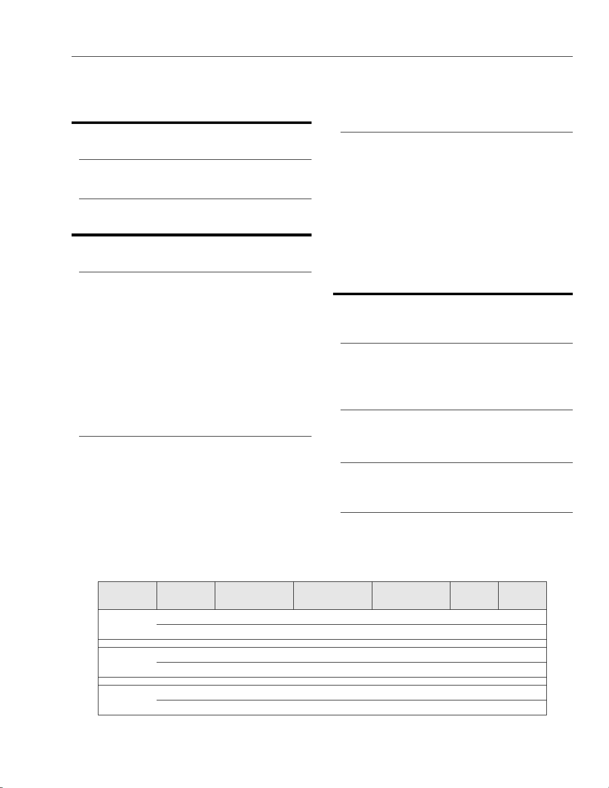
Tab le 1 - 1 .
Machine GVW and Wheel Loads
VP MODEL CONFIG. GVW (no load)
10VP ANSI (U.S.) 930 lb. (422 kg) 424 lb. 216 lb. 76 psi 102 psi
CSA (CAN.) 930 lb. (422 kg) 424 lb. 216 lb. 76 psi 102 psi
15VP ANSI (U.S.) 1,355 lb. (615 kg) 604 lb. 249 lb. 108 psi 117 psi
CSA (CAN.) 1,425 lb. (647 kg) 630 lb. 257 lb. 113 psi 121 psi
20VP ANSI (U.S.) 1,910 l b. (867 kg) 750 lb. 400 lb. 134 psi 188 psi
CSA (CAN.) 2,100 lb. (953 kg) 774 lb. 470 lb. 140 psi 220 psi
DRIVE WHEEL
(ea) w/rated load
CASTER
(ea) w/rated load
PSI
(Drive)
PSI
(Caster)
3120728 – JLG Lift – 1-1
SECTION 1 - SPECIFICATIONS
Base Footprint
VP Series - 32 in. (81cm) width 56 in. (1.42m) length
Max. Platform Height (mast extended)
10VP – 10 ft. 6 in.(3.2m)
15VP – 15 ft.(4.5m)
20VP – 19 ft. 9 in.(5.9m)
Platform Working Height (average)
10VP –16 ft. 6 in.(4.8m)
15VP –21 ft.(6.4m)
20VP –25 ft. 9 in.(7.6m)
Machine Drive Speed (max.)*
Platform Lowered - 2 mph (3.22 kph)
Platform Elevated - 0.5 mph (.81 kph)
(reduced by limit switch)
* Variable to maximum with speed cut back.
Amperage Draw (average)
Lift - 12 amps.Drive - 20 amps.
Interlock Switch Operating Conditions
Table 1-4. shown, lists machine response to various interlock switch positions.
1.5 LUBRICATION
Hydraulic Oil
Hydraulic oils must have anti-wear qualities at least to API
Service Classification GL-3, and sufficient chemical stability for mobile hydraulic system service. JLG Industries,
recommends Mobilfluid 424 hydraulic oil, which has an
SAE viscosity of 10W-30 and a viscosity index of 152.
For cold weather applications, i.e. when temperatures
remain consistently below +20°F (–7°C) JLG recommends using Mobil DTE 13 hydraulic oil.
Aside from JLG recommendations, it is not advisable to
mix oils of different brands or types, as they may not contain the same required additives or be of comparable viscosities. If use of hydraulic oil other than Mobilfluid 424 is
desired, contact JLG Industries for proper recommendations.
Table 1-2. Hydraulic Oil Operating Range
HYDRAULIC SYSTEM OPERATING
TEMPERATURE RANGE
0 ° F t o +2 3 ° F
(-18° C to -5° C)
0° F to +210° F
( -1 8 ° C t o +9 9 ° C )
50° F to 210° F
(+10° C to +210° C)
SAE VISCOSITY
GRADE
10W
10W-20, 10W-30
20W-20
Lubrication Specifications
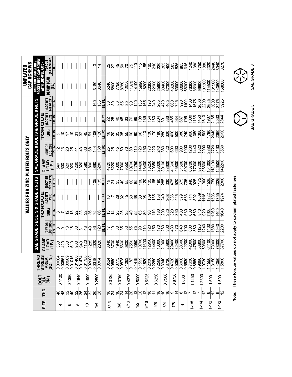
1.4 TORQUE REQUIREMENTS
When maintenance becomes necessary or a fastener has
loosened, refer to the Torque Chart, Figure 1-3., Torque
Chart. to determine proper torque value.
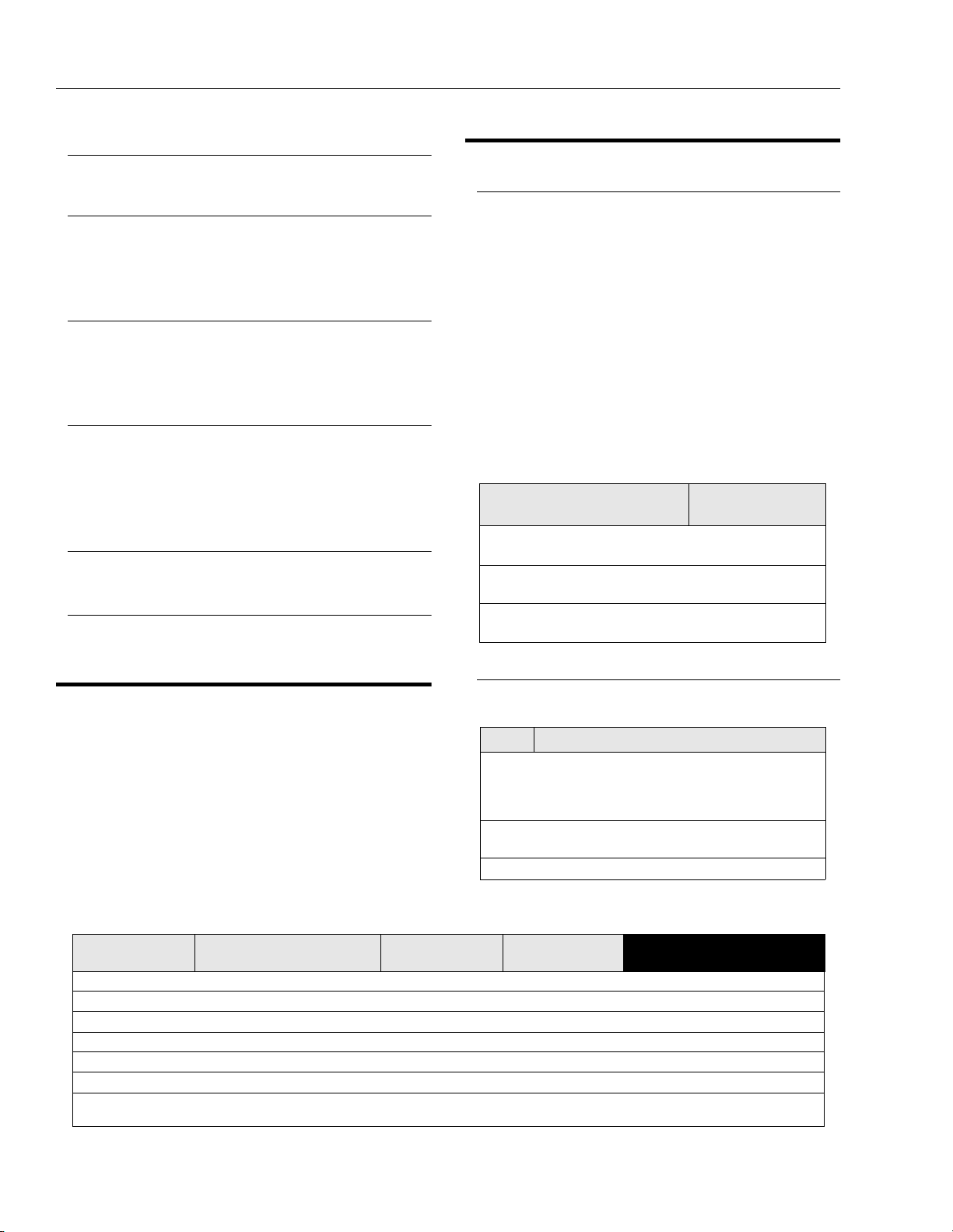
Table 1-4. Machine Interlock Switch Operating Conditions.
Mast Elevation
mast retracted bars raised (not tilted) engaged Full Dr ive and Lift
mast retracted bars raised (not tilted) disengaged Drive and Lift Disabled
mast extended bars lowered (not tilted) engaged Drive 25% maximum
mast extended bars raised (blocked) (not tilted) engaged Drive Disable d
mast extended bars lowered (tilt) engaged Drive and Lift disabled
mast retracted bars raised (tilt) engaged Lift Disabled
mast retracted
Drive Cutout
(PHP System)
bars raised/battery charger
plugged-in
Tilt Status Brake Status Controller Response
(not tilted) engaged Drive Disable d
Table 1-3. Lubrication Specifications
KEY SPECIFICATIONS
Multipurpose Grease having a minimum dripping point
MPG -
EPGL -
HO - Hydraulic Oil. ISO-Vg grade 32, 46.
of 350° F. Excellen t water resistance and adhe sive qualities, and being of extreme pressure type. (Timken OK
40 poun ds minimum.)
Extreme Pressure Gear Lube (oil) meeting API service
classification GL-5 or MIL-Spec MIL-L-2105.
1-2 – JLG Lift – 3120728

1.6 HYDRAULIC PRESSURE ADJUSTMENT
RETURN
SECTION 1 - SPECIFICATIONS
Adjust system pressure so that platform will raise with
rated capacity in platform.
The following are recommended factory pressure settings;
VP10,VP15 –1000 psi
VP20 – 2500 psi
Turning adjustment screw clockwise increases system
pressure, turning screw counterclockwise decreases
system pressure.
Make pressure adjustment with oil at normal operating
temperature. If pressure is set when oil is cold, platform
may not raise rated load after oil has warmed.
PRESSURE
ADJUSTMENT
SCREW
ADJUSTMENT
SCREW CAP
LINE
REPLACE ELBOW
WITH A T-FITTING
TO CONNECT
PRESSURE GAUGE
HERE
EXTEND
LINE
PRESSURE
GAUGE
Figure 1-2. Hydraulic Pressure Gauge Installation.
1.7 CYLINDER SPECIFICATIONS
NOTE: All dimensions are given in inches (in), with the met-
ric equivalent, centimeters (cm), given in parentheses.
Table 1-5. Cylinder Specifications
Figure 1-1. Hydraulic Pressure Setting - Adjustment
Screw Located at Base of Pump Motor
(Remove Hex Head Cap as Shown)
ONLY OPEN HYDRAULIC SYSTEM LINES WITH THE MAST LOW-
DESCRIPTION
Lift Cylinder 10VP
Lift Cylinder 15VP
Lift Cylinder 20VP
BORE
in./(cm)
1.50
(3.81)
1.50
(3.81)
1.50
(3.81)
STROKE
in./(cm)
54.50
(138.43)
54.50
(138.43)
54.50
(138.43)
ROD DIA.
in./(cm)
1.125
(2.86)
1.125
(2.86)
1.125
(2.86)
ERED TO RELIEVE PRESSURE IN THE SYSTEM. CAREFULLY
LOOSEN REQUIRED FITTINGS, WEAR SAFETY PROTECTION
EQUIPMENT WHEN WORKING WITH HYDRAULIC SYSTEMS.
Connect pressure gauge as shown in Figure 1-2., Hydraulic Pressure Gauge Installation.
1.8 SERIAL NUMBER LOCATION
For machine identification, a serial number plate is affixed
to the machine. The plate is located on the back of the
mast, just above the mast support bracket.
Select a T-Fitting to exactly match the thread size of the
pump (.562 x 18 THD), pressure line (.562 x 18 THD) and
gauge fitting as required.
3120728 – JLG Lift – 1-3
SECTION 1 - SPECIFICATIONS
Figure 1-3. Torque Chart.
1-4 – JLG Lift – 3120728
SECTION 1 - SPECIFICATIONS
6
1
2
3
Figure 1-4. Lubrication Chart.
Table 1-6.Lubrication Intervals for Various Components
ITEM COMPONTENT
1Hydraulic Oil
Drive Wheel
2
Bearings
Drive Wheel
3
Gear Box
4 Caster Axle s 2 - Grease Fitt ing MPG - Pressure Gun
5 Swivel Raceways 2 - Front Casters MPG - Pressure Gun
6 Mast Chains * 2 - Per Section
* Ap p li e s On l y t o Ma s t Se c ti o ns w i th C ha i ns .
Key to Lubricants: MPG - Multipurpose Grease
NO/TYPE
LUBE POINTS
F il l To Li n e o n
Reservoir
5 Qt. Reservoir
4 - Grease Fittings MPG- Pressure Gun
2 - Gear Box Gear Oil
HO - Hydra ulic Oil - See Sectio n 1.5, "Lubrication" in Service Manua l.
GEAR OIL - Good Quality Worm Gear Oil - SAE 90 - AGMA#5 - EP Compounded
LUBE/METHOD
HO - Check Hyd. Oil
L e ve l
HO - Change Hyd. Oil
Chain Lube - Brush or
Spray
3
MONTHS
150 Hrs.
✔
✔
✔
✔
4, 5
INTERVAL HOURS
6
MONTHS
300 Hrs.
1
YEAR
600 Hrs.
2
YEARS
1200 Hrs.
✔
COMMENTS
Check Hydraulic Oil every 10 hrs.
Change Hydr aulic Oil every 1 200
hrs.
Change only when serviced
requires 6 oz. (175 cc ’s) to fill.
Inspect, lubricate if dry or rusting.
Notes: 1. Be certain t o lubricate like items on each side of the machine.
2. Recommended lubricating intervals are based on nor mal use. If machine is subjected to severe operating conditions,
such as a high number of cycles, location, corrosive/dir ty environment, etc., user must adjust lubricating requirements accordingly.
3. Prior to checking hydraulic oil level, operate machine through one complete cycle of lift function (full up and down). Failure t o do s o wi l l
result in incorrect oil level reading on the hydraulic reservoir.
3120728 – JLG Lift – 1-5

SECTION 1 - SPECIFICATIONS
This page intentionally left blank
1-6 – JLG Lift – 3120728
SECTION 2 - SERVICE PROCEDURES
SECTION 2. SERVICE PROCEDURES
2.1 GENERAL
This section provides general information to assist in the
performance of maintenance on the personnel lift.
Descriptions, techniques and specific procedures are
designed to provide the safest and most efficient maintenance for use by personnel responsible for ensuring the
correct installation and operation of machine components
and systems.
WHEN AN ABNORMAL CONDITION IS NOTED AND PROCEDURES
CONTAINED HEREIN DO NOT SPECIFICALLY RELATE TO THE
NOTED IRREGULARITY, WORK SHOULD BE STOPPED AND
TECHNICALLY QUALIFIED GUIDANCE OBTAINED BEFORE WORK
IS RESUMED.
2.2 SERVICING AND MAINTENANCE
GUIDELINES
General
The following information is provided to assist you in the
use and application of servicing and maintenance procedures contained in this chapter.
selves. As soon as a line or component is disconnected,
cap or cover all openings to prevent entry of foreign matter.
Clean and inspect all parts during servicing or maintenance, and assure that all passages and openings are
unobstructed. Cover all parts to keep them clean. Be sure
all parts are clean before they are installed. New parts
should remain in their containers until they are ready to be
used.
Components Removal and Installation
Use adjustable lifting devices, whenever possible, if
mechanical assistance is required. All slings (chains,
cables, etc.) should be parallel to each other and as near
perpendicular as possible to top of part being lifted.
Should it be necessary to remove a component on an
angle, keep in mind that the capacity of an eyebolt or similar bracket lessens, as the angle between the supporting
structure and the component becomes less than 90
degrees.
If a part resists removal, check to see whether all nuts,
bolts, cables, brackets, wiring, etc., have been removed
and that no adjacent parts are interfering.
Component Disassembly and Reassembly
Safety and Workmanship
Your safety, and that of others, is the first consideration
when engaging in the maintenance of equipment. Always
be conscious of component weight. Never attempt to
move heavy parts without the aid of a mechanical device.
Do not allow heavy objects to rest in an unstable position.
When raising a portion of the equipment, ensure that adequate support is provided.
NEVER WORK UNDER AN ELEVATED PLATFORM UNTIL PLATFORM HAS BEEN SAFELY RESTRAINED FROM ANY MOVEMENT
BY BLOCKING OR OVERHEAD SLING.
Cleanliness
The most important single item in preserving the long service life of a machine is to keep dirt and foreign materials
out of the vital components. Precautions have been taken
to safeguard against this. Shields, covers, seals, and filters are provided to keep the wheel bearings, mast sections and oil supply clean; however, these items must be
maintained on a scheduled basis in order to function
properly.
At any time when oil lines are disconnected, clear adjacent areas as well as the openings and fittings them-
When disassembling or reassembling a component, complete the procedural steps in sequence. Do not partially
disassemble or assemble one part, then start on another.
Always recheck your work to assure that nothing has been
overlooked. Do not make any adjustments, other than
those recommended, without obtaining proper approval.
Pressure-Fit Parts
When assembling pressure-fit parts, use an “anti-seize” or
molybdenum disulfide base compound to lubricate the
mating surface.
Bearings
When a bearing is removed, cover it to keep out dirt and
abrasives. Clean bearings in nonflammable cleaning solvent and allow to drip dry. Compressed air can be used
but do not spin the bearing.
Discard bearings if the races and balls (or rollers) are pitted, scored, or burned.
If bearing is found to be serviceable, apply a light coat of
oil and wrap it in clean (waxed) paper. Do not unwrap
reusable or new bearings until they are ready to install.
Lubricate new or used serviceable bearings before installation. When pressing a bearing into a retainer or bore,
3120728 – JLG Lift – 2-1
SECTION 2 - SERVICE PROCEDURES
apply pressure to the outer race. If the bearing is to be
installed on a shaft, apply pressure to the inner race.
Gaskets
Check that holes in gaskets align with openings in the
mating parts. If it becomes necessary to hand-fabricate a
gasket, use gasket material or stock of equivalent material
and thickness. Be sure to cut holes in the right location, as
blank gaskets can cause serious system damage.
Bolt Usage and Torque Application
Use bolts of proper length. A bolt which is too long will
bottom before the head is tight against its related part. If a
bolt is too short, there will not be enough thread area to
engage and hold the part properly. When replacing bolts,
use only those having the same specifications of the original, or one which is equivalent.
Unless specific torque requirements are given within the
text, standard torque values should be used on heattreated bolts, studs, and steel nuts, in accordance with
recommended shop practices. (See Figure 1-1.)
Hydraulic Lines and Electrical Wiring
Clearly mark or tag hydraulic lines and electrical wiring, as
well as their receptacles, when disconnecting or removing
them from the unit. This will assure that they are correctly
reinstalled.
Hydraulic System
Keep the system clean. If evidence of metal or rubber particles is found in the hydraulic system, drain and flush the
entire system.
Disassemble and reassemble parts on clean work surface. Clean all metal parts with non-flammable cleaning
solvent. Lubricate components, as required, to aid assembly.
Lubrication and Servicing
Components and assemblies requiring lubrication and
servicing are shown in the Lubrication Chart, (See Figure
1-2.). Service applicable components with the amount,
type, and grade of lubricant recommended in this manual,
at the specified intervals. When recommended lubricants
are not available, consult your local supplier for an equivalent that meets or exceeds the specifications listed.
Batteries
Clean batteries, using a non-metallic brush and a solution
of baking soda and water. Rinse with clean water. After
cleaning, thoroughly dry batteries and coat terminals with
an anti-corrosion compound.
Mast Chain Inspection Procedure
MAST CHAINS TO BE INSPECTED AND LUBRICATED EVERY
THREE MONTHS.
Inspect mast chains for the following conditions:
Wear: Always inspect that segment of chain that operates
over a sheave. As the chain flexes over the sheaves, joints
and plate edges very gradually wear. Chain “stretch” can
be measured using a manufacturers wear scale or steel
tape. When chains have elongated 3% they must be
removed and replaced. Refer to Table 2-1 for proper chain
specifications and allowable stretch tolerances. Peening
and wear of chain plate edges are caused by sliding over
a chain worn contact face of a sheave, or unusually heavy
loads. All of the above require replacement of the chain
and correction of the cause. Chain side wear, noticeable
when pin heads and outside plates show a definite wear
pattern, is caused by misalignment of the sheave/chain
anchors and must be corrected promptly. Do not repair
chains; if a section of chain is damaged, replace the entire
chain set.
Rust and Corrosion: Rust and corrosion will cause a
major reduction in the load carrying capacity of the chain,
because these are primary reasons for side plate cracking. The initial lubrication at the factory is applied in a hot
dip tank to assure full penetration into the joint. Do not
steam clean or degrease chains. At time of chain installation, factory lube must be supplemented by a maintenance program to provide a film of oil on the chains at all
times. If chains are corroded, they must be inspected,
especially the outside plates, for cracks in-line with the
pins. If cracks are found, replace the chain; if no cracks
are discovered, lubricate the chains by dipping in heated
oil, and reinstall on the machine. Keep chains lubricated.
Table 2-1. Chain Stretch Tolerance
Chain Size
.50" pitch 12" or 24 pitches . 24 in./12 in. span
.625 pitch 15" or 24 pitches .30 in./1 5 in. span
Fatigue Cracks: Fatigue is a phenomenon that affects
most metals, and is the most common cause of chain
plate failures. Fatigue cracks are found through the link
holes, perpendicular (90 degrees) from the pin in-line
position. Inspect chains carefully after long time use and
heavy loading for this type of crack. If any cracks are discovered, replace all chains, as seemingly sound plates
are on the verge of cracking. Fatigue and ultimate
strength failures on JLG Lifts are incurred as a result of
severe abuse as design specs are well within the rated lifting capacity of these chains.
Pin to Pin
Measurement
Allowable Stretch
2-2 – JLG Lift – 3120728
SECTION 2 - SERVICE PROCEDURES
Tight Joints: All joints in the leaf chain should flex freely.
On leaf chain, tight joints are usually caused by rust/corrosion, or the inside plates “walking” off the bushing. Limber
up rusty/corroded chains (after inspecting care fully) with
a heavy application of oil (preferably a hot oil dip). Tap
inside “ walking” plates inward; if “walking” persists,
replace the chain. This type of problem is accelerated by
poor lubrication maintenance practice, and most tight
joint chains have been operated with little or no lubrication. Tight joints on leaf chain are generally caused by:
a. Bent pins or plates.
b. Rusty joints.
c. Peened plate edges.
Oil rusty chains, and replace chains with bent or peened
chain components. Keep chains lubricated.
Protruding or Turned Pins: Chains operating with inadequate lube generate tremendous friction between the pin
and plates (pin and bushing on leaf chain). In extreme
cases, this frictional torque can actually turn the pins in
the outside press-fit plates. Inspect for turned pins, which
can be easily spotted as the “V” flats on the pin heads are
no longer in line. Replace all chains showing evidence of
turned or protruding pins. Keep chains lubricated.
Chain Anchors and Sheaves: An inspection of the chain
must include a close examination of chain anchors and
sheaves. Check chain anchors for wear breakage and
misalignment. Anchors with worn or broken fingers should
be replaced. They should also be adjusted to eliminate
twisting the chain for an even load distribution.
Inspect the sheaves, sheave bearings, sheave grooves
and pins for extreme wear, replace as necessary. A worn
sheave can mean several problems, as follows:
a. Chains too tight.
b. Sheave bearings/pin bad.
c. Bent/misaligned chains.
Mast Cable Inspection Procedure
Inspection should be more frequent as cables approach
the end of their useful lives.
Only the surface wires of the cable require inspection, do
not attempt to open the cable. Any deterioration resulting
in any loss of original strength, such as described below,
shall be noted, and then a determination made if further
use would constitute a hazard.
Mast cables must be replaced after machine has been in
service for five (5) years, regardless of cable condition, or
sooner if conditions dictate.
Conditions such as the following shall be sufficient reason
for questioning continual use of the [cable] or increasing
the frequency of inspection:
1. In running ropes, six randomly distributed broken
wires in one lay or three broken wires in one strand
in one lay.
2. One outer wire broken at the point of contact with
the core of the rope which has worked its way out of
the rope structure and protrudes or loops out from
the rope structure. Additional inspection of this section is required.
3. Wear of one-third the original diameter of outside
individual wires.
4. Kinking, crushing, birdcaging or any other damage
resulting in distortion of the rope structure.
5. Evidence of any heat damage from any cause.
6. Reductions from nominal diameter of more than;
a. 1/64th in. (0.4mm) for diameters up to and
including 5/16th in. (8mm);
NOTE: A good indicator of a stretched extend/retract cable
is if the adjusting nuts are bottomed out. If no adjustment remains the cables have stretched and need
replacement.
Also check for cracked, bent, worn, severely corroded, or
improperly installed cable ends.
Inspect sheaves, sheave grooves, and sheave pins for
excessive wear, replace as necessary.
MAST CABLES ARE TO BE INSPECTED EVERY THREE MONTHS
OR MORE FREQUENTLY AS DESCRIBED FOLLOWING.
2.3 LUBRICATION INFORMATION
Hydraulic System
WEAR PROTECTIVE GLOVES TO PROTECT HANDS WHEN HANDLING CABLE.
The periodic inspection shall cover the entire length of the
cable. The inspection frequency shall be based on such
factors as expected cable life as determined by experience on the particular application or similar installations,
severity of environment, percentage of capacity lifts, frequency rates of operation, and exposure to shock loads.
3120728 – JLG Lift – 2-3
The primary enemy of a hydraulic system is contamination. Contaminants enter the system by various means,
e.g., using inadequate hydraulic oil, allowing moisture,
grease, filings, sealing components, sand, etc., to enter
when performing maintenance, or by permitting the pump
to cavitate due to insufficient system warm-up or leaks in
the pump supply.
The design and manufacturing tolerances of the component working parts are very close, therefore, even the
smallest amount of dirt or foreign matter entering a system
SECTION 2 - SERVICE PROCEDURES
can cause wear or damage to the components and generally results in faulty operation. Every precaution must be
taken to keep hydraulic oil clean, including reserve oil in
storage.
Cloudy oils indicate a high moisture content which permits organic growth, resulting in oxidation or corrosion. If
this condition occurs, the system must be drained,
flushed, and refilled with clean oil.
It is not advisable to mix oils of different brands or types,
as they may not contain the same required additives or be
of comparable viscosities. Good grade mineral oils, with
viscosities suited to the ambient temperatures in which
the machine is operating, are recommended for use.
NOTE: Metal particles may appear in the oil of new
machines due to the wear-in of meshing components.
Hydraulic Oil
For best performance, JLG recommends the use of ISOVg grade 32, 46 oil with a viscosity range between 15-250
SUS at 100 degrees F (32-54 cST at 40 degrees C). Refer
to Section 1-5 of this Service Manual for recommended
hydraulic oils.
Changing Hydraulic Oil
Use of any of the recommended hydraulic oils eliminates
the need for changing the oil on a regular basis. If it is necessary to change the oil, use only those oils meeting or
exceeding the specifications appearing in this manual. If
unable to obtain the same type of oil supplied with the
machine, consult local supplier for assistance in selecting
the proper equivalent. Avoid mixing petroleum and synthetic base oils. JLG Industries recommends changing the
hydraulic oil annually.
Use every precaution to keep the hydraulic oil clean. If the
oil must be poured from the original container into
another, be sure to clean all possible contaminants from
the service container.
While the unit is shut down, a good preventive maintenance measure is to make a thorough inspection of all
hydraulic components, lines, fittings, etc., as well as a
functional check of each system, before placing the
machine back in service.
Lubrication Specifications
Specified lubricants, as recommended by the component
manufacturers, are always the best choice, however,
multi-purpose greases usually have the qualities which
meet a variety of single purpose grease requirements.
Should any question arise regarding the use of greases in
maintenance stock, consult your local supplier for evaluation. Refer to Table 1-3 in this Service Manual for an explanation of the lubricant key designations appearing in the
Lubrication Chart.
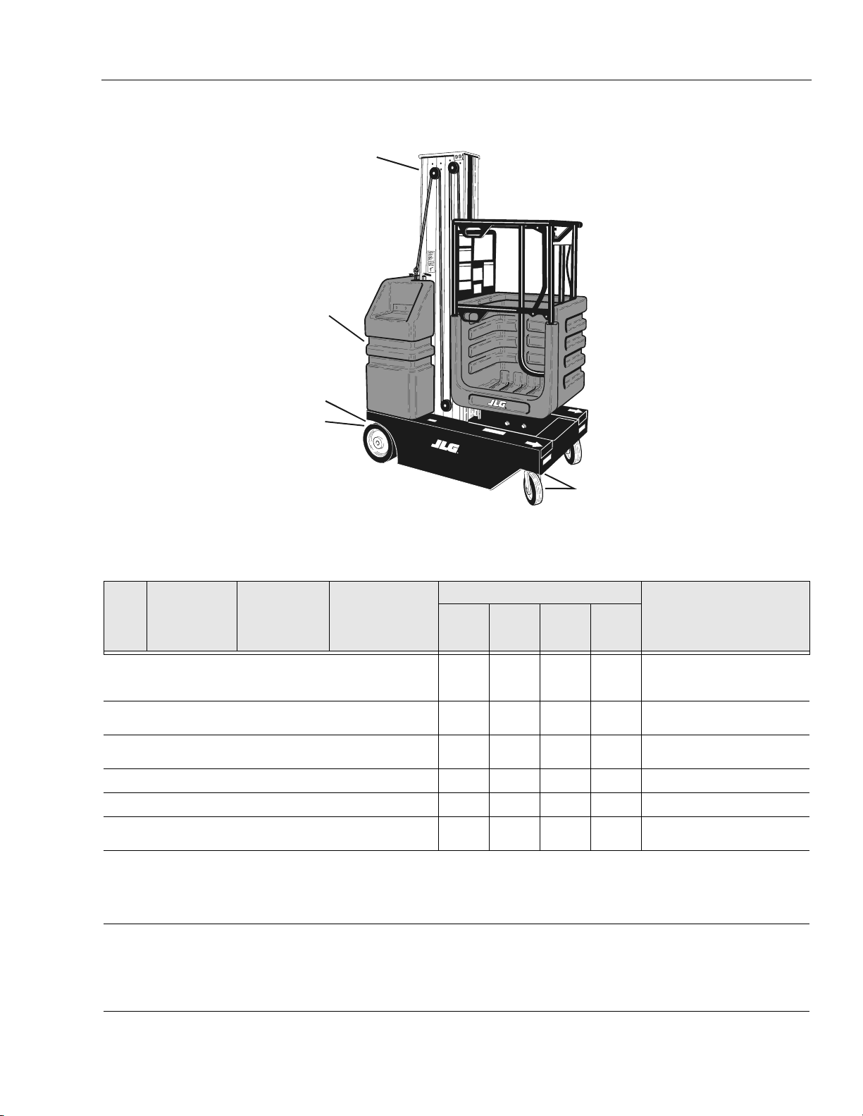
2.4 POSITIONING LIFT FOR ACCESS TO
COMPONENTS LOCATED UNDER THE
BASE FRAME
Access to the underside of the VP lift can be obtained by
lifting the machine with a fork lift truck, using the fork lift
pockets in the base frame.
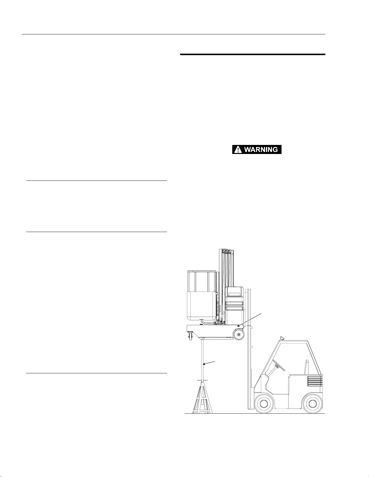
Lifting with a Fork Truck (See Figure 2-1.)
1. Choose a fork lift truck capable of safely handling
the full weight of the machine.
2. Locate work area on a firm, level surface.
KEEP MACHINE LEVEL OR SLIGHTLY TILTED TOWARD FORKLIFT
TRUCK WHEN LIFTING TO PREVENT MACHINE FROM SLIDING
OFF LIFTING TINES.
3. When lifting with a fork truck, lift only using the fork
lift-truck pockets running the length of the machine’s
base frame from rear to front.
4. After lifting machine to desired work height, place
support stands under the machine. The support
stands must reach from the floor to the bottom of the
machine and be capable of safely handling the
weight of the machine.
LIFT USING ONLY THE
FORK LIFT POCKETS
RUNNING THE LENGTH
OF THE BASE FRAME
PLACE
SUPPORT
STAND
BETWEEN
MACHINE
AND
FLOOR
Figure 2-1. Accessing Machine Underside
Components by Lifting with a Fork Truck.
2-4 – JLG Lift – 3120728
SECTION 2 - SERVICE PROCEDURES
2.5 DRIVE MOTOR COMPONENT SERVICE
PROCEDURES
Torque Limiting Clutch Maintenance
VP Series machines are equipped with a torque limiting
clutch coupling on each drive axle. The clutch is mounted
inline on the drive axle between the drive wheel and the
drive motor gear box. The clutch is designed to slip at a
pre-set torque if the machines rear wheels are over-driven
while the machine is being towed, pushed or forklifted,
thus preventing damage to the drive gear box. Although
factory pre-set, the clutch assembly and torque should be
checked at the following interval:
• Every 3 months.
Visual Inspection and Limiting Torque
Checking Procedure
1. Locate the machine on a firm level surface.
KEEP MACHINE LEVEL OR SLIGHTLY TILTED TOWARD FORKLIFT
TRUCK WHEN LIFTING TO PREVENT MACHINE FROM SLIDING
OFF LIFTING TINES.
2. Carefully raise the lift to gain access to the underside of the base frame. Refer to Section 2.4, "Positioning Lift For Access to Components Located
Under the Base Frame".
3. Locate the clutch assembly on each rear drive axle
and check for the following;
a. Check the coupling chains for any loose or miss-
ing parts, i.e. pins, links, etc., replace if necessary.
b. Check that the allen-head set screws on the
(large) clutch adjusting nut are in place and
secure. Tighten or replace if necessary.
c. Check for any debris wedged in or wrapped
around the clutch coupling chains and axle
shafts. Remove debris and clean area if necessary.
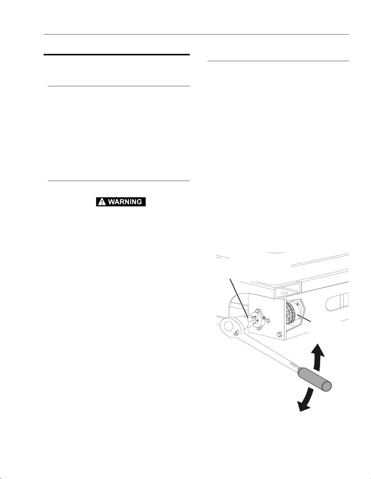
Checking Clutch - Torque Setting (ft. lb.)
NOTE: Check that the machines brakes are engaged before
applying torque to the rear drive wheels.
1. Remove the drive wheels from the drive axles.
2. Select a torque wrench capable of setting a torque
of at least 185 ft. lb. Insert special tool (P/N-
0080229) into a 3/4" socket on the torque wrench.
3. Slide the tool onto the end of the drive axle aligning
the key on the axle shaft (install key on axle, if necessary), with key slot in the tool. (See Figure 2-2.)
4. Turn the torque wrench and note the torque setting
when the torque limiting clutch releases. The torque
(slip) setting should be set at 185 ft. lb. Check both
rear drive axles.
NOTE: The allowable breaking torque for the torque limiting
clutch can be set as much as 35 ft. lb. less than the
factory setting of 185 ft. lb., but never more than the
185 ft. lb. factory setting.
5. If torque setting is OK, re-install the wheels and
lower machine, IF NOT, see the following note.
NOTE: If torque setting is outside the allowable range of
specifications, the torque limiting clutch will need
adjustment. See Torque Limiting Clutch Adjustment
following.
SERVICE TOOL
P/N-0080229
(REQUIRES A 1-3/4” SOCKET)
TORQUE
LIMITING
CLUTCH
LOCATION
Figure 2-2. Check Torque Limit Clutch -
Torque Setting.
3120728 – JLG Lift – 2-5
SECTION 2 - SERVICE PROCEDURES
TORQUE LIMIT
CLUTCH
ADJUSTING NUT
ADJUSTING NUT
SET SCREWS
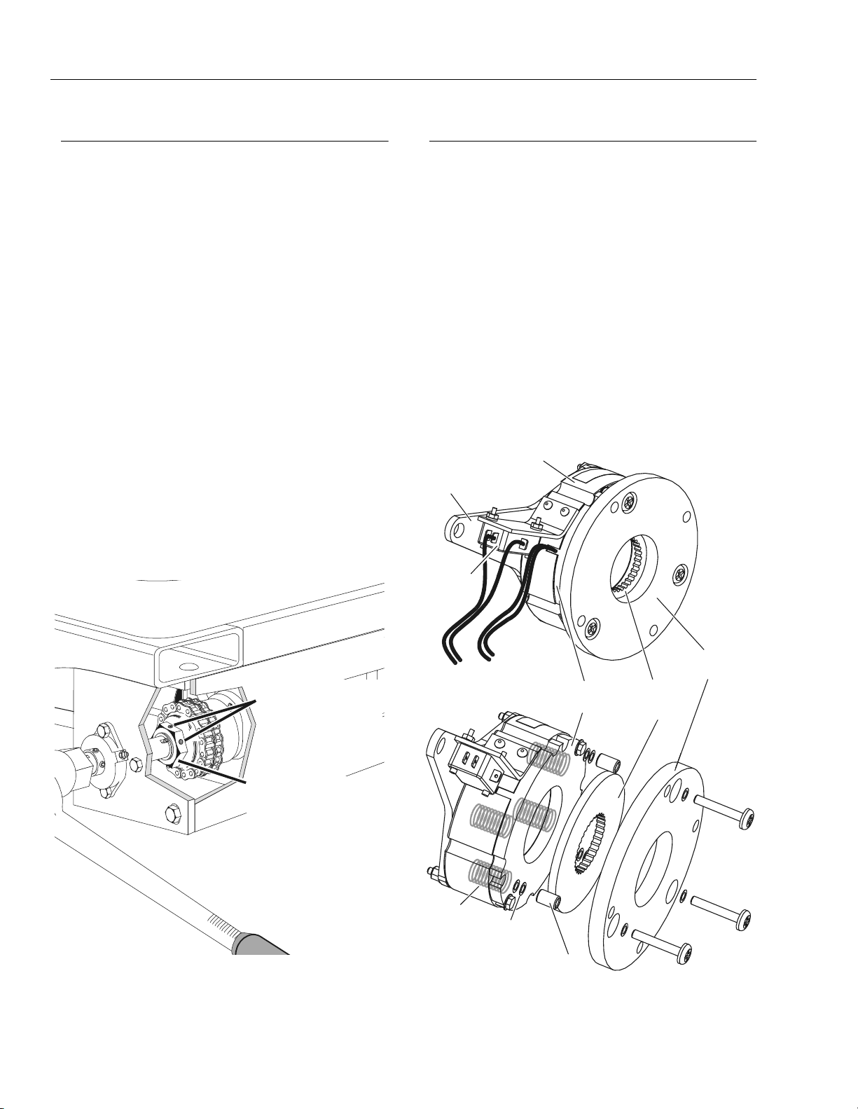
Torque Limiting Clutch Adjustment
NOTE: The large adjusting nut on the side of the clutch
assembly is a standard type thread.
If the torque (slip) setting of the clutch assembly is
under spec (by more than 35 ft. lb.), the large adjusting nut must be (tightened) turned clockwise to
increase the torque setting.
If the torque (slip) setting is over spec (over 185 ft.
lb.) the large adjusting nut must be (loosened),
turned counter-clockwise to decrease the torque setting.
1. Loosen the two (2) adjusting nut setscrews located
on the large adjusting nut on the clutch assembly.
(See Figure 2-3.)
2. Hold the drive axle steady using service tool (P/N-
0080229) and the torque wrench used to check the
torque setting.
3. Depending on how far off the original torque setting
was (see note at beginning of this procedure),
tighten or loosen the adjusting nut accordingly, then
recheck the (slip) torque setting.
4. When proper torque setting is achieved, re-tighten
the two (2) adjusting nut, setscrews.
5. Re-install the drive wheels, remove the jack stand
and lower the machine to ground.
Drive Motor Brake Adjustment/Removal
(See Figure 2-4. & Figure 2-5.)
Mounted onto the front of each drive motor housing is a
brake assembly. The brakes are normally ENGAGED
(brakes on) when the machine is parked and are
RELEASED electrically (brakes off) under normal driving
conditions, when the joystick is enabled and pushed in
any direction. The brakes can also be RELEASED manually using the manual brake release lever mounted on the
side of the mast.
NOTE: The brakes are intended only as parking brakes to
keep the machine from moving while at rest. The
brakes are not used to stop the machine during driving operations, this braking is controlled by the drive
motors themselves. Under normal driving conditions,
once released the brakes are not engaged again
until the machine comes to a complete stop.
MANUAL
BRAKE
RELEASE
ARM
LIMIT
(MICRO)
SWITCH
MAGNETIC
COIL
HOUSING
MOUNTING
PLATE
ARMATURE
PLATE
FRICTION
BRAKE
DISK
SPRINGS
SHIM WASHERS
Figure 2-3. Torque Limit Clutch -
Adjustment Components.
(AS REQUIRED)
SPACER
Figure 2-4. Brake Assembly Components
2-6 – JLG Lift – 3120728
SECTION 2 - SERVICE PROCEDURES
E
FRICTION BRAKE DISK FRICTION BRAKE DISK
ARMATURE PLATE ARMATURE PLATE
MAGNETIC COIL
(Not Energized)
MANUAL
RELEASE ARM/
ADJUSTMENT
SCREW
GAP SETTINGS - BRAKE ON
(Magnet Not Energized)
MOUNTING PLATE MOUNTING PLAT
0.006” GAP
BETWEEN
ARMATURE
PLATE AND
MAGNETIC COIL
0.020” GAP
UNDER
SCREW HEAD
BETWEEN
ARMATURE
PLATE
MAGNETIC COIL
(Energized)
MANUAL
RELEASE ARM/
ADJUSTMENT
SCREW
GAP SETTINGS - BRAKE RELEASED
Figure 2-5. Brake Armature Plate & Brake Disk Adjustment.
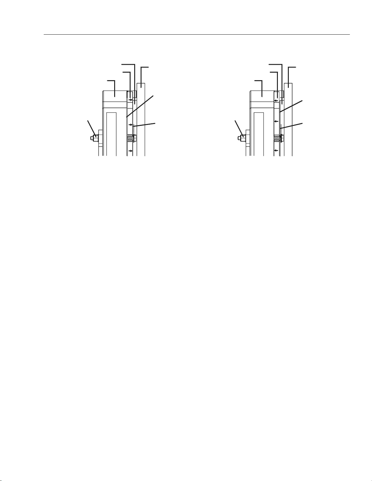
Operation (See Figure 2-4. & Figure 2-5.)
When the magnetic coil is not energized (brake on), the
armature plate is pushed away from the magnetic coil surface by heavy springs internally mounted in the magnetic
coil housing. This pressure forces the armature plate
against the friction brake disk holding it tight between the
armature plate and the mounting plate. The brake is not
released until either the magnetic coil is energized pulling
the armature plate away from the friction brake disk or the
brake is manually released using the manual brake
release handle.
A correctly adjusted brake will ideally have a measurment
of approximately .006" (but will operate normally at .004" to
.010") between the armature plate and magnetic coil
housing surface when the brakes are ENGAGED (brakes
3. With the brakes ENGAGED measure the air gap
between the armature plate and the magnetic coil
housing. The correct setting should be .006", however the brakes will operate properly if the measurement is a minimum of .004" and a maximum of .010".
(See Figure 2-5.)
4. If the air gap falls outside the maximum allowable
setting of .010" the friction disk has worn. To correct
this replace the disk with a new one.
5. It the air gap is below the minimum allowable setting
of .004", recheck the areas between the magnetic
coil housing, armature plate, friction disk and
mounting plate for debris. Clean as neccessary. Also
check that the manual release arm screws are not
tightened to tight.
on).
Never allow any type of lubricant (oil, grease, hydraulic
fluid, etc.) to come in contact with the brake friction disk or
it’s contacting surfaces. Also if the brake becomes
clogged with debris or dirt the brake may not release
properly.
Manual Release Arm - Screw Adjustment
NOTE: Always check the armature plate gap setting is within
spec before attempting to adjust the manual release
arm screw adjustment.
1. With the brakes ENGAGED (brakes on) the air gap
Checking/Adjusting Armature Plate Gap Setting
1. First inspect that all parts of the brake assembly are
tight and secure. Tighten as necessary.
2. Inspect the brake for any debris which may be
lodged in the air gap between the armature plate
and magnetic coil when the brakes are ENGAGED
(brakes on); on either side of the friction disk when
the brake is RELEASED (brakes off); or any dirt or
debris lodged between the manual release arm and
the magnetic coil housing. Clean and remove debris
as necessary.
under the head of the manual release arm screw to
the surface of the armature plate should be set at
.020". Adjust using the locknut on the release arm
end of the screw.
2. With the brakes electrically RELEASED (brakes off)
the air gap under the screw head increases to
approximately .026" due to the armature plate movement towards the magnetic coil, releasing the friction brake disk. When the brakes are RELEASED
(brakes off) manually the screw head pulls in against
the armature plate releasing the friction brake disk.
0.006” GAP
BETWEEN
FRICTION
DISK AND
ARMATURE
PLATE
0.026” GAP
UNDER
SCREW HEAD
BETWEEN
ARMATURE
PLATE
(Magnet Energized)
3120728 – JLG Lift – 2-7
SECTION 2 - SERVICE PROCEDURES
S
Brake Assembly Removal
1. Lift the machine to gain access to the underside
(See Section 2-4., "Positioning Lift For Access To
Components Located Under The Base Frame").
2. Disconnect the brake magnetic coil wiring connector
and the brake limit (micro) switch wiring connector
from their wiring harness connectors.
3. Disconnect the manual brake release cable from the
manual brake release arm attached to the brake
assembly.
4. Lower machine back down to ground level.
PLACE MACHINE ON A LEVEL SURFACE BEFORE BEFORE
REMOVING THE BRAKE ASSEMBLIES. MACHINE MAY ROLL
AWAY IF NOT SETTING ON A LEVEL SURFACE.
5. Using the Ground Control Switch, raise the platform
to gain access to the brake assemblies mounted on
the end of the drive motors located at the base of the
mast.
NEVER WORK UNDER AN ELEVATED PLATFORM UNTIL PLATFORM HAS BEEN SAFELY RESTRAINED FROM ANY MOVEMENT
BY BLOCKING OR OVERHEAD SLING.
6. Remove the four (4) hex cap screws securing the
brake assembly to the end of the drive motor and
remove the brake assembly from the end of the
drive motor.
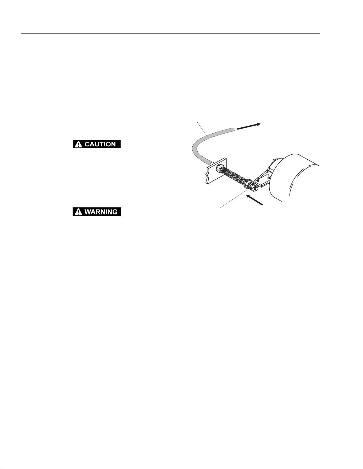
6. Reconnect the manual release brake cable to the
manual release lever (Y shaped lever) and adjust
cable so brakes are released when manual release
lever is in the down position. (See Figure 2-6.)
MANUAL
RELEASE
BRAKE
CABLE
SET MANUAL
BRAKE RELEASE
HANDLE TO
FREE WHEELING
AND ADJUST HERE
UNTIL BRAKE DISK
IS COMPLETELY
RELEA
ED
TO MANUAL
RELEASE
BRAKE
HANDLE
MOUNTED
ON SIDE OF
MAST
BRAKES
ARE RELEASED
WHEN CABLE
PULLS LEVER
IN THIS DIRECTION
Figure 2-6. Manual Release Brake Cable Adjustment.
Brake Assembly Installation
1. Guide the manual release lever, brake coil and brake
limit switch wiring connectors through the opening
in the drive motor cover and base frame while sliding the brake assembly onto the front of the drive
motor. Engage the teeth of the disk brake with the
teeth on the drive motor brake gear.
2. If necessary, manually release the brake disk using
the manual release lever to allow the brake assembly to turn and align the four holes in the brake
mounting plate with the mating holes in the drive
motor end plate.
3. Secure the brake assembly to the drive motor using
four (4) hex cap screws with washers. Torque evenly
to 44 in. lbs.
4. Lift the machine to gain access to the underside
(See Section 2-4., "Positioning Lift For Access To
Components Located Under The Base Frame").
5. Reconnect the brake coil and brake limit switch wiring connectors to their respective wiring harness
connectors.
2-8 – JLG Lift – 3120728
SECTION 2 - SERVICE PROCEDURES
OTO
(2 EACH INSIDE FORK LIFT POCKET)
DRIVE MOTOR MOUNT
DRIVE MOTOR MOUNT
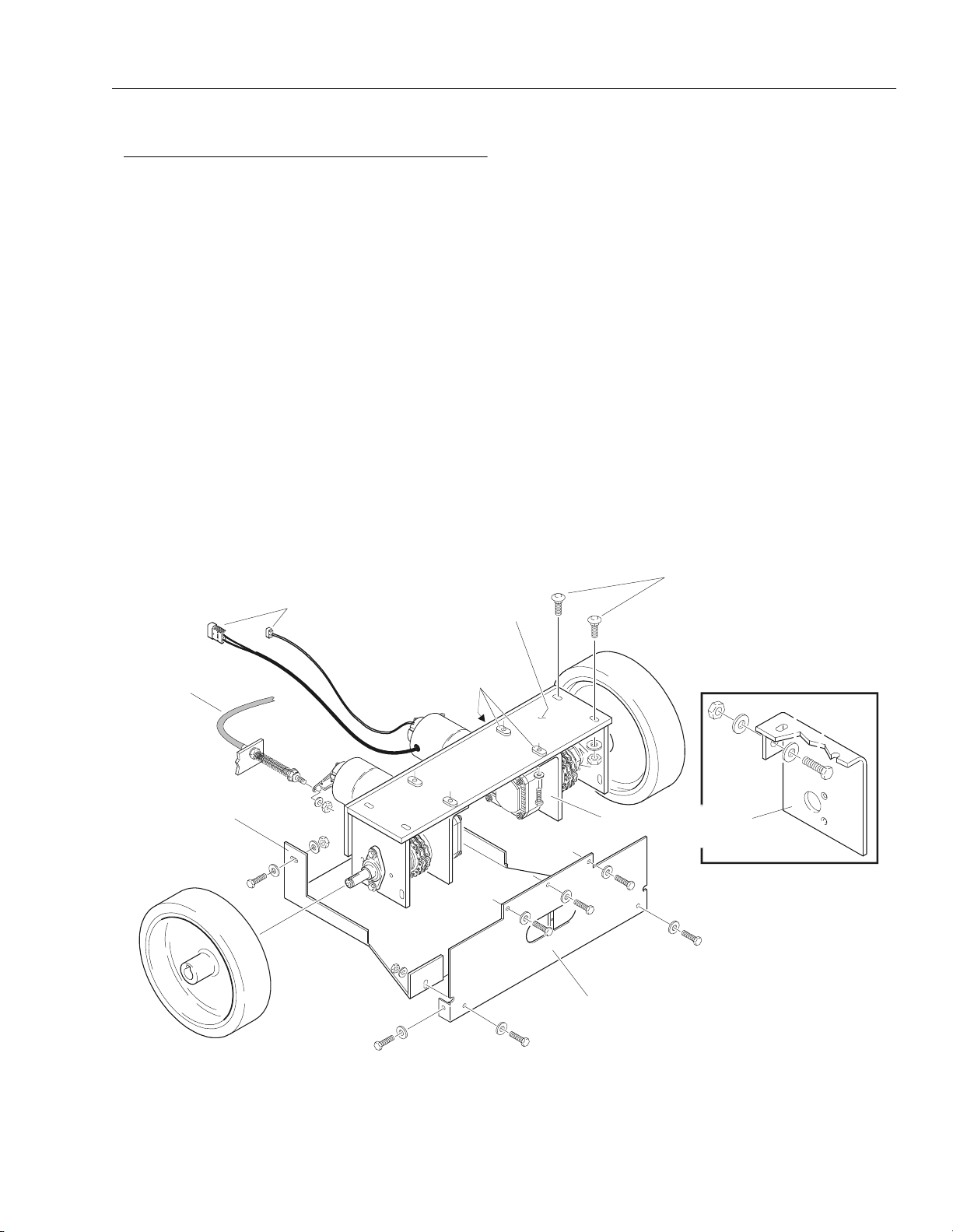
Drive Motor Removal
(See Figure 2-7.)
The VP drive motors consist of three sections, the gear
box atttached to the rear of the drive motor, the electric
drive motor itself, and the brake assembly mounded at the
front of the drive motor. Each drive motor is mounted independently of the other on a completely removable drive
assembly weldment at the back of the machine.
1. Disconnect the positive battery terminal from the left
side battery.
2. Remove the rear plate weldment from the machine,
(plate with the tie down lug) and set aside. Three (3)
bolts hold the top of the rear plate weldment to the
base frame, four (4) bolts attach it to the motor cover
weldment (located under machine) at the back and
on the sides.
3. Carefully raise the lift to gain access to the underside of the base frame. Refer to Section 2.4, "Positioning Lift For Access to Components Located
Under the Base Frame".
4. Remove the remaining two (2) bolts attaching the
motor cover to the base frame and set it aside.
DRIVE MOTOR/
BRAKE WIRING
CONNECTORS
DRIVE MOTOR
ASSEMBLY WELDMENT
5. Disconnect the wiring connectors to the drive motor
and the brake assembly on either or both sides,
depending on which drive assembly(ies) is being
removed.
6. Disconnect the manual release brake cable from the
brake assembly arm on either or both drive motors if
removing the complete drive assembly.
NOTE: If removing each drive motor seperately continue to
Step 7. If removing the complete drive assembly
with both motors attached go to Step 11.
7. Remove the one (1) bolt, nut, and two (2) washers
from the front of the drive motor mounting plate.
8. While holding the drive motor in place, remove the
remaining two (2) bolts with washers holding the
drive motor mounting plate to the drive motor
assembly weldment.
9. Slide the drive motor and torque limiting clutch
assembly towards the center of the machine, sliding
the torque limiting clutch off the outer drive shaft.
10. Move drive motor assembly and torque limiting
clutch to a suitable work bench for disassembly.
DRIVE M
ASSEMBLY
WELDMENT
ATTACH BOLTS
R
MANUAL
RELEASE
BRAKE
CABLE
DRIVE MOTOR
PLATE FASTENERS
(THREE ON EACH MOUNT
ALSO SEE INSET)
COVER
PLATE
REAR PLATE
WELDMENT
Figure 2-7. Drive Motor Assembly Removal.
3120728 – JLG Lift – 2-9
SECTION 2 - SERVICE PROCEDURES
Gear Box Disassembly/Assembly
IF REMOVING THE COMPLETE DRIVE ASSEMBLY, IT WEIGHS
APPROXIMATELY XX LB. AND WILL REQUIRE ASSISTANCE TO
LOWER. PREFERABLY USE A MOVABLE TRANSMISSSION OR
OTHER HYDRAULIC JACK TO CAREFULLY LOWER ASSEMBLY
FROM UNDER MACHINE.
11. Carefully remove the four (4) nuts and washers
(outer most holes on the drive assembly weldment)
from the carriage bolts attaching the drive motor
assembly to the base frame. Be aware of the weight
of the assembly before completely removing the fasteners, see the CAUTION above.
12. Lower the drive assembly and place on a suitable
work surface.
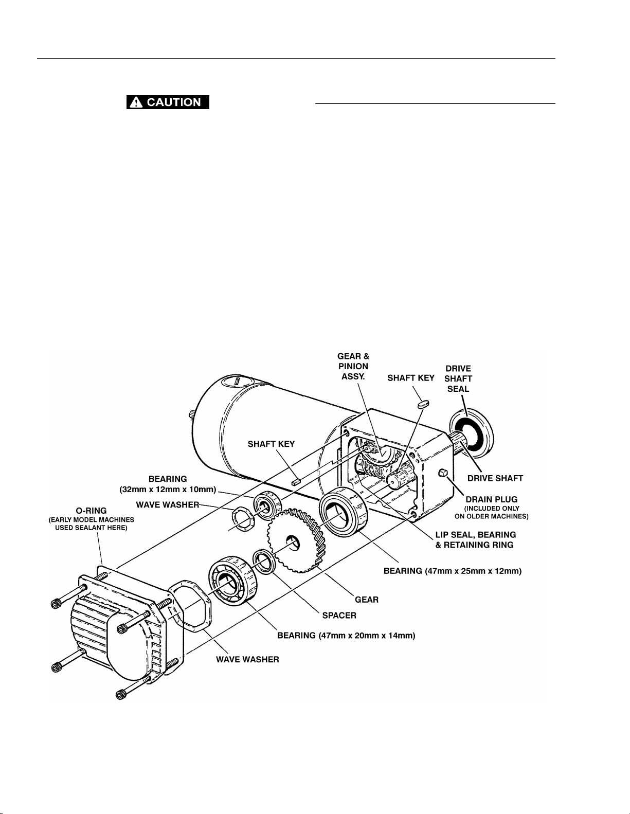
(See Figure 2-8.)
The drive motor gear box is mounted on the rear of each
drive motor transferring power from the electric drive
motor to the rear drive wheels. It is a right angle worm
gear type box with a 50:1 reduction drive ratio. The internal gears and bearings of the gear box are lubricated by
175cc’s of gear oil in an unvented aluminum alloy housing. Early VP machines included a oil drain plug on the
rear surface of the gear box housing, later model
machines do not. The following procedures disassemble
and assemble the gear box housing internal components.
Gear Box Disassembly (See Figure 2-8.)
1. Remove the drive motor/gear box/brake assembly
from the machine using the procedure outlined previously in this section of the manual.
Figure 2-8. Drive Motor Gear Box Assembly.
2-10 – JLG Lift – 3120728
SECTION 2 - SERVICE PROCEDURES
S
G
NOTE: The gear oil can be drained out when the side cover
is removed in the next step. Remove the side cover
from the gear box with the drive shaft side pointing
down, then tilt drive motor/gear box assembly to
drain the oil into a suitable container.
2. Remove the four (4) hex cap screws securing the
side cover to the gear box housing, and remove the
side cover and rubber seal ring. (Note: Early model
machines did not have the rubber seal ring and were
sealed with sealant only.) Be careful not to scratch or
gouge the mating surfaces between the cover and
the gear box housing. This area is sealed by the rubber ring/sealant and may leak oil if damaged.
3. Remove the wave washers from atop the large and
small bearings and lay inside their respective holes
in the side cover.
4. Using a suitable catch container, drain the gear oil
from the gear box housing.
5. Remove the drive shaft assembly from the housing.
Place the drive motor/gear box assembly on a
hydraulic press with the open side of the gear box
housing facing down. Support the gear box housing
surface but do not block the free travel of the drive
gear and bearings, on the drive shaft or the pinion
gear assembly.
6. With the open surface of the housing properly supported, carefully press the drive shaft down through
until it is free of the housing. When the drive shaft
assembly is free, slide it completely out of the housing.
7. To remove the large (47mm) (cover side) bearing
and (housing side) bearing from the drive shaft, use
a suitable hydraulic press and press the bearing(s)
off the shaft. Keep the spacer from between the
cover side bearing and the drive shaft gear for reuse
during assembly.
8. To remove the small (32mm) bearing(s) from the
gear (brass) and pinion assembly, use a suitable
hydrauic press and press the bearing(s) off the gear
and pinion shaft.
9. To remove the (brass) worm gear from the pinion
assembly, use a suitable hydraulic press and press
the gear off the pinion shaft. Keep the (brass) gear
key for reuse during assembly.
10. Inspect the drive shaft seal for cuts, cracks and
wear, or if showing signs of leakage. Replace if necessary.
Gear/Pinion Shaft Assembly (See Figure 2-9.)
1. Locate the pinion gear/shaft, place the key for the
(brass) worm gear into the slot on the gear shaft.
2. Press the (brass) worm gear onto the pinion shaft
and align the keyway in the (brass) worm gear with
the key on the pinion shaft. Press the (brass) worm
gear onto the shaft until it bottoms out against the
pinion gear teeth.
NOTE: Press bearings onto the shaft pressing only against
the bearing inner race. Do not press against the
outer race or damage could occur to the bearing.
3. Press the small (32mm) bearings onto the ends of
the pinion shaft. The inner race of the bearing on the
pinion gear side can be bottomed out against the
pinion gear. Do not press the bearing on the (brass)
worm gear side of the shaft in tight against the
(brass) worm gear. This bearing must be flush with
the end of the shaft on the outside, yet have clearance from the (brass) worm gear on the inside, so it
can rotate freely.
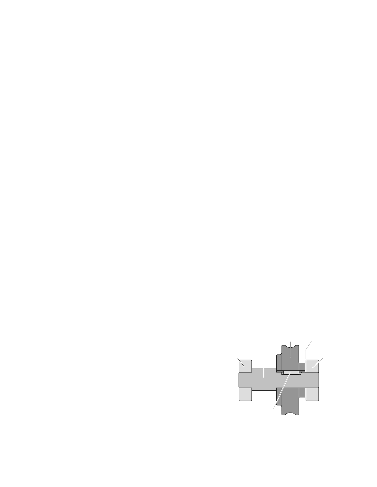
Drive Shaft Assembly (See Figure 2-10.)
1. Slide the (housing side), 42mm x 25mm x 12mm
(thinner) bearing onto the long end of the drive shaft.
Press the bearing inner race until it bottoms against
the shaft shoulder between the drive gear and the
bearing.
2. Slide the narrow spacer onto the drive gear end of
the shaft and press the (cover side) 42mm x 20mm x
14mm (wider) bearing onto the drive shaft until it
bottoms against the spacer. This bearing should be
flush with the end of the drive shaft.
IDE PROFILE
32mm
BEARING
WORM
GEAR
(BRASS)
PINION GEAR/
SHAFT
LEAVE
GAP HERE
32mm
BEARIN
WORM GEAR
KEY
Figure 2-9. Gear/Pinion Shaft Assembly.
3120728 – JLG Lift – 2-11

SECTION 2 - SERVICE PROCEDURES
O
G
Final Gear Box Assembly
1. If necessary, install a new drive shaft lip seal into the
drive shaft hole in the gear box housing before
assembling the drive shaft gear set into the gear
box. Install the seal so it is even with the bottom of
the chamfer in the drive shaft hole on the outside of
the housing and flush with the bearing seat on the
inside of the housing.
2. Lube the drive shaft seal with a thin film of oil before
sliding the drive shaft over the seal.
3. Position the gear box with open cover side up, allow
space under the gear box for the drive shaft to
extend through without obstruction.
4. Hold the gear and pinion, and drive shaft assembies
together with the pinion gear and the ring gear on
the drive shaft meshing. Now carefully slide these
assemblies into the gear box housing sliding the
drive shaft through the drive shaft lip seal.
NOTE: While assembling the gear assemblies into the gear
box housing, be careful with the drive shaft seal and
the softer brass worm gear and brass drive worm
gear from the drive motor.
5. Continue to drop the gear assemblies into the gear
box, align the bearings with the bearing seats in the
housing on both assemblies. Drop the gear and pinion (smaller) bearing into it’s seat first, while wiggling
that gear set align the drive shaft bearing and wiggle
it into it’s seat. When both are seated continue to
next step.
6. With the gear box still positoned with the open cover
side up, fill the gear box with six (6) ounces (U.S.)
(175cc’s) of good quality worm gear oil (Specifica-
tion - SAE 90 weight - AGMA#5 - EP Compounded).
When pouring the gear oil, wet the gears and bearings with the oil.
7. Wet with gear oil and place the large wave washer
on the end of the drive shaft bearing and the small
wave washer on the end of the gear and pinion bearing.
8. Clean the mating surfaces of the side cover and the
gear box and check that the cover dow guide pins
are properly installed in the cover.
9. On older model gear boxes apply sealant to the
cover mating surface on the gear box. On newer
model gear boxes insert the rubber seal into the
groove in the cover.
10. Using the cover dow guide pins, place the cover
onto the gear box housing.
11. Secure using the four (4) hex cap screws, torque
screws evenly to 90 in. lbs.
12. Install the drive motor back onto the machine.
N
PINI
GEAR
SPACER
PINION GEAR KEY
42mm x 25mm x 12mm
BEARING
DRIVE SHAFT
SIDE PROFILE
42mm x 20mm x 14mm
BEARIN
Figure 2-10. Drive Shaft Assembly.
2-12 – JLG Lift – 3120728
 Loading...