


An Oshkosh Corporation Company
Service Manual
Models
3508PS, 3509PS,
3512PS, 3513PS,
4008PS, 4009PS,
4012PS, 4013PS,
4017PS,
Agrovector
40.8, 40.9
31200206
Revised
June 15, 2011


EFFECTIV IT Y PAGE
September 11, 2007 - A - Original Issue Of Manual
April 4, 2008 - B - Revised pages 2.7, 2-8, 3.12, 3.27, 5.11, 7.3, 7.7, 7.8, 8.2, 8.9, 9.10, 9.28 and pages 9.30 thru 9.70.
Added platform information.
June 15, 2011 - C - Update all
Loctite® 242
TM
, to Loctite
Revised pages 1-3, 2-3 thru 2-9, 2-13, 8-6 thru 8-16, 9-11 thru 9-21 & 9-34 thru 9-45.
®
243
TM
. Added models 40.8 & 40.9. Revised page numbering.
31200206 3508PS, 3509PS, 3512PS, 3513PS, 4008PS, 4009PS, 4012PS, 4013PS, 4017PS, 40.8, 40.9
a

EFFECTIV IT Y PAGE
b
3508PS, 3509PS, 3512PS, 3513PS, 4008PS, 4009PS, 4012PS, 4013PS, 4017PS, 40.8, 40.9 31200206

SECTION CONTENTS
Section Subject Page
Section 1
Safety Practices . . . . . . . . . . . . . . . . . . . . . . . . . . . . . . . . . . . . . . . . . . . . . . . . . . . . . . . 1.1
1.1 Introduction . . . . . . . . . . . . . . . . . . . . . . . . . . . . . . . . . . . . . . . . . . . . . . . . . . . . . . . . . . 1.2
1.2 Disclaimer . . . . . . . . . . . . . . . . . . . . . . . . . . . . . . . . . . . . . . . . . . . . . . . . . . . . . . . . . . . 1.2
1.3 Operation & Safety Manual . . . . . . . . . . . . . . . . . . . . . . . . . . . . . . . . . . . . . . . . . . . . . . 1.2
1.4 Do Not Operate Tags . . . . . . . . . . . . . . . . . . . . . . . . . . . . . . . . . . . . . . . . . . . . . . . . . . . 1.2
1.5 Safety Information . . . . . . . . . . . . . . . . . . . . . . . . . . . . . . . . . . . . . . . . . . . . . . . . . . . . . 1.2
1.6 Safety Instructions . . . . . . . . . . . . . . . . . . . . . . . . . . . . . . . . . . . . . . . . . . . . . . . . . . . . . 1.3
1.7 Safety Decals. . . . . . . . . . . . . . . . . . . . . . . . . . . . . . . . . . . . . . . . . . . . . . . . . . . . . . . . . 1.4
Section 2
General Information and Specifications . . . . . . . . . . . . . . . . . . . . . . . . . . . . . . . . . . . . 2.1
2.1 Replacement Parts and Warranty Information. . . . . . . . . . . . . . . . . . . . . . . . . . . . . . . . 2.2
2.2 Torque Charts . . . . . . . . . . . . . . . . . . . . . . . . . . . . . . . . . . . . . . . . . . . . . . . . . . . . . . . .2.3
2.3 Specifications. . . . . . . . . . . . . . . . . . . . . . . . . . . . . . . . . . . . . . . . . . . . . . . . . . . . . . . . . 2.11
2.4 Fluids, Lubricants and Capacities . . . . . . . . . . . . . . . . . . . . . . . . . . . . . . . . . . . . . . . . . 2.13
2.5 Maintenance Schedules. . . . . . . . . . . . . . . . . . . . . . . . . . . . . . . . . . . . . . . . . . . . . . . . . 2.15
2.6 Lubrication Schedules . . . . . . . . . . . . . . . . . . . . . . . . . . . . . . . . . . . . . . . . . . . . . . . . . . 2.16
Section 3
Boom . . . . . . . . . . . . . . . . . . . . . . . . . . . . . . . . . . . . . . . . . . . . . . . . . . . . . . . . . . . 3.1
3.1 Boom System Component Terminology - Two and Three Section Boom . . . . . . . . . . . 3.3
3.2 Boom System - Two and Three Section Boom . . . . . . . . . . . . . . . . . . . . . . . . . . . . . . . 3.4
3.3 Boom Assembly Maintenance - Two and Three Section Boom. . . . . . . . . . . . . . . . . . . 3.4
3.4 Boom System Component Terminology - Four Section Boom. . . . . . . . . . . . . . . . . . . . 3.8
3.5 Boom System - Four Section Boom. . . . . . . . . . . . . . . . . . . . . . . . . . . . . . . . . . . . . . . . 3.9
3.6 Boom Assembly Maintenance - Four Section Boom . . . . . . . . . . . . . . . . . . . . . . . . . . . 3.9
3.7 Boom Extend and Retract Chains Four Section Boom . . . . . . . . . . . . . . . . . . . . . . . . . 3.18
3.8 Boom Section Separation Adjustment - Four Section Boom . . . . . . . . . . . . . . . . . . . . . 3.21
3.9 Hose Carrier Assembly - Four Section Boom . . . . . . . . . . . . . . . . . . . . . . . . . . . . . . . . 3.22
3.10 Boom Wear Pads. . . . . . . . . . . . . . . . . . . . . . . . . . . . . . . . . . . . . . . . . . . . . . . . . . . . . . 3.25
3.11 Quick Switch Assembly . . . . . . . . . . . . . . . . . . . . . . . . . . . . . . . . . . . . . . . . . . . . . . . . . 3.26
3.12 Forks . . . . . . . . . . . . . . . . . . . . . . . . . . . . . . . . . . . . . . . . . . . . . . . . . . . . . . . . . . . . . . . 3.27
3.13 Troubleshooting . . . . . . . . . . . . . . . . . . . . . . . . . . . . . . . . . . . . . . . . . . . . . . . . . . . . . . .3.28
Section 4
Cab and Covers . . . . . . . . . . . . . . . . . . . . . . . . . . . . . . . . . . . . . . . . . . . . . . . . . . . . . . . . 4.1
4.1 Operator Cab and Covers Component Terminology . . . . . . . . . . . . . . . . . . . . . . . . . . . 4.2
4.2 Operator Cab . . . . . . . . . . . . . . . . . . . . . . . . . . . . . . . . . . . . . . . . . . . . . . . . . . . . . . . . .4.3
4.3 Cab Components. . . . . . . . . . . . . . . . . . . . . . . . . . . . . . . . . . . . . . . . . . . . . . . . . . . . . . 4.3
4.4 Cab Removal . . . . . . . . . . . . . . . . . . . . . . . . . . . . . . . . . . . . . . . . . . . . . . . . . . . . . . . . . 4.9
4.5 Cab Installation . . . . . . . . . . . . . . . . . . . . . . . . . . . . . . . . . . . . . . . . . . . . . . . . . . . . . . . 4.11
3508PS, 3509PS, 3512PS, 3513PS, 4008PS, 4009PS, 4012PS, 4013PS, 4017PS, 40.8, 40.9
i

Section Subject Page
Section 5
Axles, Drive Shafts, Wheels and Tires . . . . . . . . . . . . . . . . . . . . . . . . . . . . . . . . . . . . . . 5.1
5.1 Axle, Drive Shaft and Wheel Component Terminology . . . . . . . . . . . . . . . . . . . . . . . . . 5.2
5.2 General Information . . . . . . . . . . . . . . . . . . . . . . . . . . . . . . . . . . . . . . . . . . . . . . . . . . . . 5.3
5.3 Axle Assemblies. . . . . . . . . . . . . . . . . . . . . . . . . . . . . . . . . . . . . . . . . . . . . . . . . . . . . . . 5.3
5.4 Drive Shafts . . . . . . . . . . . . . . . . . . . . . . . . . . . . . . . . . . . . . . . . . . . . . . . . . . . . . . . . . . 5.9
5.5 Wheels and Tires . . . . . . . . . . . . . . . . . . . . . . . . . . . . . . . . . . . . . . . . . . . . . . . . . . . . . . 5.10
5.6 Brakes . . . . . . . . . . . . . . . . . . . . . . . . . . . . . . . . . . . . . . . . . . . . . . . . . . . . . . . . . . . . . . 5.11
5.7 Towing A Disabled Machine. . . . . . . . . . . . . . . . . . . . . . . . . . . . . . . . . . . . . . . . . . . . . . 5.12
Section 6
Transmission: . . . . . . . . . . . . . . . . . . . . . . . . . . . . . . . . . . . . . . . . . . . . . . . . . . . . . . . . .6.1
6.1 Transmission Assembly Component Terminology . . . . . . . . . . . . . . . . . . . . . . . . . . . . . 6.2
6.2 Transmission Description. . . . . . . . . . . . . . . . . . . . . . . . . . . . . . . . . . . . . . . . . . . . . . . . 6.3
6.3 Transmission Serial Number . . . . . . . . . . . . . . . . . . . . . . . . . . . . . . . . . . . . . . . . . . . . . 6.3
6.4 Transmission Specifications. . . . . . . . . . . . . . . . . . . . . . . . . . . . . . . . . . . . . . . . . . . . . . 6.3
6.5 Transmission Replacement . . . . . . . . . . . . . . . . . . . . . . . . . . . . . . . . . . . . . . . . . . . . . . 6.3
6.6 Troubleshooting . . . . . . . . . . . . . . . . . . . . . . . . . . . . . . . . . . . . . . . . . . . . . . . . . . . . . . . 6.7
Section 7
Engine: Perkins 1104-42 & 1104-42T . . . . . . . . . . . . . . . . . . . . . . . . . . . . . . . . . . . . . . . 7.1
7.1 Introduction . . . . . . . . . . . . . . . . . . . . . . . . . . . . . . . . . . . . . . . . . . . . . . . . . . . . . . . . . . 7.2
7.2 Engine Serial Number . . . . . . . . . . . . . . . . . . . . . . . . . . . . . . . . . . . . . . . . . . . . . . . . . . 7.4
7.3 Specifications and Maintenance Information . . . . . . . . . . . . . . . . . . . . . . . . . . . . . . . . . 7.4
7.4 Engine Cooling System . . . . . . . . . . . . . . . . . . . . . . . . . . . . . . . . . . . . . . . . . . . . . . . . . 7.4
7.5 Engine Electrical System . . . . . . . . . . . . . . . . . . . . . . . . . . . . . . . . . . . . . . . . . . . . . . . . 7.6
7.6 Fuel System . . . . . . . . . . . . . . . . . . . . . . . . . . . . . . . . . . . . . . . . . . . . . . . . . . . . . . . . . .7.6
7.7 Engine Exhaust System. . . . . . . . . . . . . . . . . . . . . . . . . . . . . . . . . . . . . . . . . . . . . . . . . 7.8
7.8 Air Cleaner Assembly. . . . . . . . . . . . . . . . . . . . . . . . . . . . . . . . . . . . . . . . . . . . . . . . . . . 7.9
7.9 Engine Replacement . . . . . . . . . . . . . . . . . . . . . . . . . . . . . . . . . . . . . . . . . . . . . . . . . . . 7.9
7.10 Engine Drive Plate . . . . . . . . . . . . . . . . . . . . . . . . . . . . . . . . . . . . . . . . . . . . . . . . . . . . . 7.12
7.11 Troubleshooting . . . . . . . . . . . . . . . . . . . . . . . . . . . . . . . . . . . . . . . . . . . . . . . . . . . . . . .7.13
Section 8
Hydraulic System . . . . . . . . . . . . . . . . . . . . . . . . . . . . . . . . . . . . . . . . . . . . . . . . . . . . . . . 8.1
8.1 Hydraulic Component Terminology . . . . . . . . . . . . . . . . . . . . . . . . . . . . . . . . . . . . . . . . 8.2
8.2 Safety Information . . . . . . . . . . . . . . . . . . . . . . . . . . . . . . . . . . . . . . . . . . . . . . . . . . . . . 8.3
8.3 Hydraulic Pressure Diagnosis . . . . . . . . . . . . . . . . . . . . . . . . . . . . . . . . . . . . . . . . . . . . 8.3
8.4 Hydraulic Circuits . . . . . . . . . . . . . . . . . . . . . . . . . . . . . . . . . . . . . . . . . . . . . . . . . . . . . .8.4
8.5 Hydraulic Schematics. . . . . . . . . . . . . . . . . . . . . . . . . . . . . . . . . . . . . . . . . . . . . . . . . . . 8.6
8.6 Hydraulic Reservoir . . . . . . . . . . . . . . . . . . . . . . . . . . . . . . . . . . . . . . . . . . . . . . . . . . . . 8.17
8.7 Hydraulic System Pump. . . . . . . . . . . . . . . . . . . . . . . . . . . . . . . . . . . . . . . . . . . . . . . . . 8.18
8.8 Auxiliary Pump (Platform Equipped Models Only) . . . . . . . . . . . . . . . . . . . . . . . . . . . . . 8.20
8.9 Valves and Manifolds. . . . . . . . . . . . . . . . . . . . . . . . . . . . . . . . . . . . . . . . . . . . . . . . . . . 8.20
8.10 Hydraulic Cylinders . . . . . . . . . . . . . . . . . . . . . . . . . . . . . . . . . . . . . . . . . . . . . . . . . . . . 8.26
ii
3508PS, 3509PS, 3512PS, 3513PS, 4008PS, 4009PS, 4012PS, 4013PS, 4017PS, 40.8, 40.9

Section Subject Page
Section 9
Electrical System . . . . . . . . . . . . . . . . . . . . . . . . . . . . . . . . . . . . . . . . . . . . . . . . . . . . . . 9.1
9.1 Electrical Component Terminology . . . . . . . . . . . . . . . . . . . . . . . . . . . . . . . . . . . . . . . . 9.3
9.2 Specifications. . . . . . . . . . . . . . . . . . . . . . . . . . . . . . . . . . . . . . . . . . . . . . . . . . . . . . . . . 9.3
9.3 Platform Interlock Checks . . . . . . . . . . . . . . . . . . . . . . . . . . . . . . . . . . . . . . . . . . . . . . . 9.4
9.4 Software Level 2 Accessibility . . . . . . . . . . . . . . . . . . . . . . . . . . . . . . . . . . . . . . . . . . . . 9.5
9.5 Operator Tools . . . . . . . . . . . . . . . . . . . . . . . . . . . . . . . . . . . . . . . . . . . . . . . . . . . . . . . .9.7
9.6 Fuses and Relays . . . . . . . . . . . . . . . . . . . . . . . . . . . . . . . . . . . . . . . . . . . . . . . . . . . . . 9.8
9.7 Electrical System Schematics . . . . . . . . . . . . . . . . . . . . . . . . . . . . . . . . . . . . . . . . . . . . 9.11
9.8 Circuit Breakdowns . . . . . . . . . . . . . . . . . . . . . . . . . . . . . . . . . . . . . . . . . . . . . . . . . . . . 9.22
9.9 Engine Start Circuit . . . . . . . . . . . . . . . . . . . . . . . . . . . . . . . . . . . . . . . . . . . . . . . . . . . . 9.24
9.10 Charging Circuit . . . . . . . . . . . . . . . . . . . . . . . . . . . . . . . . . . . . . . . . . . . . . . . . . . . . . . . 9.25
9.11 Electrical System Components . . . . . . . . . . . . . . . . . . . . . . . . . . . . . . . . . . . . . . . . . . . 9.26
9.12 Window Wiper/Washer. . . . . . . . . . . . . . . . . . . . . . . . . . . . . . . . . . . . . . . . . . . . . . . . . . 9.26
9.13 Cab Heater and Fan . . . . . . . . . . . . . . . . . . . . . . . . . . . . . . . . . . . . . . . . . . . . . . . . . . . 9.28
9.14 Switches, Solenoids, Sensors and Senders . . . . . . . . . . . . . . . . . . . . . . . . . . . . . . . . . 9.29
9.15 Load Stability Indicator (LSI) 8, 9, 12 & 13M Before S/N 1160005993 excluding 1160005949 & 1160005950
17M Before S/N 1160005937 including 1160005952, 1160005960, 1160005963,
1160005966 & 1160005978. . . . . . . . . . . . . . . . . . . . . . . . . . . . . . . . . . . . . . . . . . . . . . 9.34
9.16 Load Stability Indicator (LSI) 8, 9, 12 & 13M S/N 1160005993 & After including 1160005949 & 1160005950
17M S/N 1160005937 & After excluding 1160005952, 1160005960, 1160005963,
1160005966 & 1160005978. . . . . . . . . . . . . . . . . . . . . . . . . . . . . . . . . . . . . . . . . . . . . . 9.38
9.17 Hand Held Analyzer . . . . . . . . . . . . . . . . . . . . . . . . . . . . . . . . . . . . . . . . . . . . . . . . . . . . 9.43
9.18 Fault Codes . . . . . . . . . . . . . . . . . . . . . . . . . . . . . . . . . . . . . . . . . . . . . . . . . . . . . . . . . . 9.46
3508PS, 3509PS, 3512PS, 3513PS, 4008PS, 4009PS, 4012PS, 4013PS, 4017PS, 40.8, 40.9
iii

Section Subject Page
iv
3508PS, 3509PS, 3512PS, 3513PS, 4008PS, 4009PS, 4012PS, 4013PS, 4017PS, 40.8, 40.9

Section 1
Safety Practices
Contents
PARAGRAPH TITLE PAGE
1.1 Introduction . . . . . . . . . . . . . . . . . . . . . . . . . . . . . . . . . . . . . . . . . . . . . . . . . . . . . . . 1-2
1.2 Disclaimer . . . . . . . . . . . . . . . . . . . . . . . . . . . . . . . . . . . . . . . . . . . . . . . . . . . . . . . . 1-2
1.3 Operation & Safety Manual. . . . . . . . . . . . . . . . . . . . . . . . . . . . . . . . . . . . . . . . . . . 1-2
1.4 Do Not Operate Tags. . . . . . . . . . . . . . . . . . . . . . . . . . . . . . . . . . . . . . . . . . . . . . . . 1-2
1.5 Safety Information. . . . . . . . . . . . . . . . . . . . . . . . . . . . . . . . . . . . . . . . . . . . . . . . . . 1-2
1.5.1 Safety Alert System and Signal Words. . . . . . . . . . . . . . . . . . . . . . . . . . . 1-2
1.6 Safety Instructions . . . . . . . . . . . . . . . . . . . . . . . . . . . . . . . . . . . . . . . . . . . . . . . . . 1-3
1.6.1 Personal Hazards . . . . . . . . . . . . . . . . . . . . . . . . . . . . . . . . . . . . . . . . . . . 1-3
1.6.2 Equipment Hazards. . . . . . . . . . . . . . . . . . . . . . . . . . . . . . . . . . . . . . . . . . 1-3
1.6.3 General Hazards. . . . . . . . . . . . . . . . . . . . . . . . . . . . . . . . . . . . . . . . . . . . 1-3
1.6.4 Operational Hazards . . . . . . . . . . . . . . . . . . . . . . . . . . . . . . . . . . . . . . . . . 1-3
1.7 Safety Decals. . . . . . . . . . . . . . . . . . . . . . . . . . . . . . . . . . . . . . . . . . . . . . . . . . . . . . 1-4
3508PS, 3509PS, 3512PS, 3513PS, 4008PS, 4009PS, 4012PS, 4013PS, 4017PS, 40.8, 40.9
1-1
Safety Practices
1.1 INTRODUCTION
This service manual provides general directions for
accomplishing servic e and re pai r proc edu res. Fo ll owi ng
the procedures in this manual will help assure safety and
equipment reliability.
Read, understand and follow the information in this
manual, and obey all locally appro ved safe ty p r actices,
procedures, rules, codes, regulations and laws.
These instructions cannot cover all details or variations in
the equipment, procedures, or processes described, nor
provide directions for meeting every possible contingency
during opera tion, maintenance, or testing. When additi onal
information is desired consult the local JLG distributor.
Many factors contribute to unsafe conditions: carelessness,
fatigue, overload, inattentiveness, unfamiliarity, even
drugs and alcohol, among others. For optimal safety,
encourage everyone to think, and to act, safely.
Appropriate service methods and proper repair
procedures are essential for the safety of the individual
doing the work, for the safety of the operator, and for the
safe, reliable operation of the machine. All references to
the right side, left side, front and rear are given from the
operator seat looking in a forwar d direction.
Supplementary information is available from JLG in the
form of Service Bulletins, Service Campaigns, Service
Training Schools, the JLG website, other literature, and
through updates to the manual itself.
1.2 DISCLAIMER
1.4 DO NOT OPERATE TAGS
Place Do Not Operate Tags on the ignition key switch and
the steering wheel before attempting to perform any
service or maintenance. Remove key and disconnect
battery leads.
1.5 SAFETY INFORMATION
To avoid possible death or injury, carefully read,
understand and comply with all safety messages.
In the event of an accident, know where to obtain medical
assistance and how to use a first-aid kit and fire
extinguisher/fire suppression system. Keep emergency
telephone numbers (fire department, ambulance, rescue
squad/paramedics, police department, etc.) nearby. If
working alone, check with another person routinely to
help assure personal safety.
1.5.1 Safety Alert System and Signal Words
DANGER
DANGER indicates an imminently hazardous situation
which, if not avoided, will result in death or serious injury.
WARNING
All information in this manual is based on the latest
product information available at the time of publication.
JLG reserves the right to make changes and
improvements to its products, and to discontinue the
manufacture of any product, at its discretion at any time
without public notice or obligation.
1.3 OPERATION & SAFETY MANUAL
The mechanic must not operate the machine until the
Operation & Safety Manual has been read and
understood, training has been accomplished and
operation of the machine has been completed under the
supervision of an experienced and qualified operator.
An Operation & Safety Manual is supplied with each
machine and must be kept in the cab. In the event that the
Operation & Safety Manual is missing, consult the local
JLG distributor before proceeding.
1-2
3508PS, 3509PS, 3512PS, 3513PS, 4008PS, 4009PS, 4012PS, 4013PS, 4017PS, 40.8, 40.9
WARNING indicates a potentially hazardous situation
which, if not avoided, could result in death or serious
injury.
CAUTION
CAUTION indicates a potentially hazardous situation
which, if not avoided, may result in minor or moderate
injury.

Safety Practices
1.6 SAFETY INSTRUCTIONS
Following are general safety statements to consider before
performing maintenance procedures on the telehandler.
Additional statements related to specific tasks and
procedures are located throughout this manual and are
listed prior to any work instructi ons to prov ide safety
information before the potential of a hazard occurs.
For all safety messages, carefully read, understand and
follow the instructions before
1.6.1 Personal Hazards
PERSONAL SAFETY GEAR: Wear all the protective
clothing and personal safety gear necessary to perform
the job safely. This might include heavy gloves, safety
glasses or goggles, filter mask or respirator, safety shoes
or a hard hat.
LIFTING: NEVER lift a heavy object without the help of at
least one assistant or a suitable sling and hoist.
1.6.2 Equipment Hazards
LIFTING OF EQUIPMENT: Before using any lifting
equipment (chains, slings, brackets, hooks, etc.), verify
that it is of the proper capacity, in good working order, and
is properly attached.
NEVER stand or otherwise become positioned under a
suspended load or under raised equipment. The load or
equipment could fall or tip.
DO NOT use a hoist, jack or jack stands only to support
equipment. Always support equipment with the proper
capacity blocks or stands properly rated for the load.
HAND TOOLS: Always use the proper tool for the job;
keep tools clean and in good working order, and use
special service tool s onl y as re co mme nde d.
proceeding.
1.6.3 General Hazards
SOLVENTS: Only use approved solvents that are known
to be safe for use.
HOUSEKEEPING: Keep the work area and operator cab
clean, and remove all hazards (debris, oil, tools, etc.).
FIRST AID: Im mediately clean, dress and report a ll injuries
(cuts, abrasions, burns, etc.), no matter how minor the
injury may seem. Know the location of a First Aid Kit, and
know how to use it.
CLEANLINESS: Wear eye protection, and clean all
components with a high-pressure or steam cleaner
before attempting service.
When removing hydraulic components, plug hose ends
and connections to prevent excess leakage and
contamination. Place a suitable catch basin beneath the
machine to capture fluid run-off.
It is good practice to avoid pressure-washing electrical/
electronic components. In the event pressure-washing
the machine is needed, ensure the machine is shut down
before pressure-washing. Should pressure-washing be
utilized to wash areas containing electrical/electronic
components, it is recommended a maximum pressure of
52 bar (750 psi) at a minimum distance of 30,5 cm (12 in)
away from these components. If electrical/electronic
components are sprayed, spraying must not be direct and
for brief time periods to avoid heavy saturation,
Check and obey all Federal, State and/or Local
regulations regarding waste storage, disposal and
recycling.
1.6.4 Operational Hazards
ENGINE: Stop the engine before performing any service
unless specifically instructed otherwise.
VENTILATION: Avoid prolonged engine operation in
enclosed areas without ade quat e ventila tion.
SOFT SURFACES AND SLO P ES : NEVER work on a
machine that is parked on a soft surface or slope. The
machine must be on a hard level surface, with the whe els
blocked before performing any service.
FLUID TEMPERATURE: NEVER work on a machine
when the engine, cooling or hydraulic systems are hot.
Hot components and fluids can cause severe burns.
Allow systems to cool before proceeding.
FLUID PRESSURE: Before loosening any hydraulic or
diesel fuel component, hose or tube, turn the engine
OFF. Wear heavy, protective gloves and eye protection.
NEVER check for leaks using any part of your body; use
a piece of cardboard or wood instead. If injured, seek
medical attention immediately. Diesel fluid leaking under
3508PS, 3509PS, 3512PS, 3513PS, 4008PS, 4009PS, 4012PS, 4013PS, 4017PS, 40.8, 40.9
1-3

Safety Practices
pressure can explode. Hydraulic oil and diesel fuel
leaking under pressure can penetrate the skin, cause
infection, gangrene and other serious personal injury.
Relieve all pressure before disconnecting any
component, part, line or hose. Slowly loosen parts and
allow release of residual pressure before removing any
part or component. Before starting the engine or applying
pressure, use components, parts, hoses and pipes that
are in good condition, connected properly and are
tightened to the proper torque.
Capture fluid in an appropriate container and dispose of
in accordance with prevailing environmental regulations.
RADIATOR CAP: The cooling system is under pressure,
and escaping coolant can cause severe burns and eye
injury. To prevent personal injury, NEVER remove the
radiator cap while the cooling system is hot. Wear safety
glasses. Turn the radiator cap to the first stop and allow
pressure to escape before removing the cap completely.
Failure to follow the safety practices could result in death
or serious injury.
FLUID FLAMABILTITY: DO NOT service the fuel or
hydraulic systems near an open flame, sparks or smoking
materials.
NEVER drain or store fluids in an open container. Engine
fuel and hydraulic oil are flammable and can cause a fire
and/or explosion.
DO NOT mix gasoline or alcohol with diesel fuel. The
mixture can cause an explos ion.
PRESSURE TESTING: When conducting any test, only
use test equipment that is correctly calibrated and in good
condition. Use the correct equipment in the proper
manner, and make changes or repairs as indicated by the
test procedure to achieve the desired result.
LEAVING MACHINE: Lower the forks or attachment to
the ground before leaving the machine.
TIRES: Always keep tires inflated to the proper pressure
to help prevent tipover. DO NOT over-inflate tires.
NEVER use mismatched tire types, sizes or ply ratings.
Always use matched sets according to machine
specifications.
MAJOR COMPONENTS: Never alter, remove, or
substitute any items such as counterweights, tires,
batteries or other items that may reduce or affect the
overall weight or stability of the machine.
BATTERY: DO NOT charge a frozen battery.Charging a
frozen battery may cause it to explode. Allow the battery
to thaw before jump-starting or connecting a battery
charger.
1.7 SAFETY DECALS
Check that all safety decals are present and readable on
the machine. Refer to the Operation & Safety Manual
supplied with machine for information.
1-4
3508PS, 3509PS, 3512PS, 3513PS, 4008PS, 4009PS, 4012PS, 4013PS, 4017PS, 40.8, 40.9

Section 2
General Information and Specifications
Contents
PARAGRAPH TITLE PAGE
2.1 Replacement Parts and Warranty Information . . . . . . . . . . . . . . . . . . . . . . . . . . . 2-2
2.2 Torque Charts . . . . . . . . . . . . . . . . . . . . . . . . . . . . . . . . . . . . . . . . . . . . . . . . . . . . . 2-3
2.2.1 SAE Fastener Torque Chart . . . . . . . . . . . . . . . . . . . . . . . . . . . . . . . . . . . 2-3
2.2.2 Metric Fastener Torque Chart . . . . . . . . . . . . . . . . . . . . . . . . . . . . . . . . . . 2-7
2.2.3 Hydraulic Hose Torque Chart . . . . . . . . . . . . . . . . . . . . . . . . . . . . . . . . . . 2-10
2.3 Specifications . . . . . . . . . . . . . . . . . . . . . . . . . . . . . . . . . . . . . . . . . . . . . . . . . . . . . 2-11
2.3.1 Travel Speeds . . . . . . . . . . . . . . . . . . . . . . . . . . . . . . . . . . . . . . . . . . . . . . 2-11
2.3.2 Hydraulic Cylinder Performance Specifications. . . . . . . . . . . . . . . . . . . . . 2-11
2.3.3 Platform Hydraulic Performance Specifications . . . . . . . . . . . . . . . . . . . . 2-11
2.3.4 Electrical System. . . . . . . . . . . . . . . . . . . . . . . . . . . . . . . . . . . . . . . . . . . . 2-12
2.3.5 Engine Performance Specifications . . . . . . . . . . . . . . . . . . . . . . . . . . . . . 2-12
2.3.6 Tires. . . . . . . . . . . . . . . . . . . . . . . . . . . . . . . . . . . . . . . . . . . . . . . . . . . . . . 2-12
2.4 Fluids, Lubricants and Capacities . . . . . . . . . . . . . . . . . . . . . . . . . . . . . . . . . . . . . 2-13
2.5 Maintenance Schedules . . . . . . . . . . . . . . . . . . . . . . . . . . . . . . . . . . . . . . . . . . . . . 2-15
2.5.1 8 & 1st 50 Hour Maintenance Schedule . . . . . . . . . . . . . . . . . . . . . . . . . . 2-15
2.5.2 50, 250 & 500 Hour Maintenance Schedule . . . . . . . . . . . . . . . . . . . . . . . 2-15
2.5.3 1000 & 1500 Hour Maintenance Schedule . . . . . . . . . . . . . . . . . . . . . . . . 2-15
2.6 Lubrication Schedules . . . . . . . . . . . . . . . . . . . . . . . . . . . . . . . . . . . . . . . . . . . . . . 2-16
2.6.1 8 Hour Lubrication Schedule. . . . . . . . . . . . . . . . . . . . . . . . . . . . . . . . . . . 2-16
2.6.2 50 Hour Lubrication Schedule. . . . . . . . . . . . . . . . . . . . . . . . . . . . . . . . . . 2-18
3508PS, 3509PS, 3512PS, 3513PS, 4008PS, 4009PS, 4012PS, 4013PS, 4017PS, 40.8, 40.9
2-1
General Information and Specifications
MZ1780
1
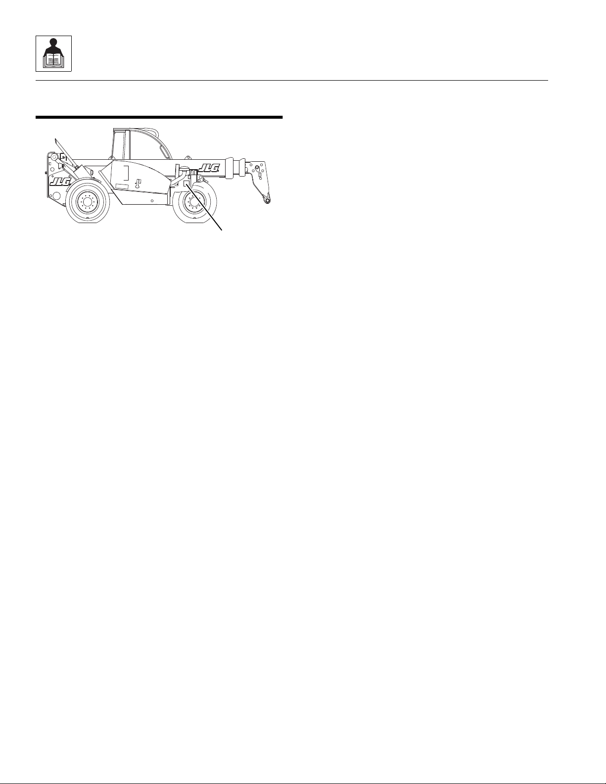
2.1 REPLACEMENT PARTS AND WARRANTY INFORMATION
For reference when ordering replacement parts or making
service inquiries about the machine, the machine serial
number is required to help assure the provision of correct
parts and information. Before ordering parts or initiating
service inquiries, make note of the serial number located
on the serial number plate (1).
Note: The replacement of any part on this machine with
any other than a JLG authorized replacement part can
adversely affect the performance, durability, or safety of
the machine, and will void the warranty. JLG disclaims
liability for any claims or damages, whether regarding
property damage, personal injury or death arising out of
the use of unauthorized replacement parts.
A warranty registration form must be filled out by the JLG
distributor, signed by the purchaser and returned to JLG
when the machine is sold and/or put into use.
Registration activates the warranty period and helps to
assure that warranty claims are promptly processed. To
guarantee full warranty service, verify that the distributor
has returned the business reply card of the warranty
registration form to JLG.
2-2
3508PS, 3509PS, 3512PS, 3513PS, 4008PS, 4009PS, 4012PS, 4013PS, 4017PS, 40.8, 40.9
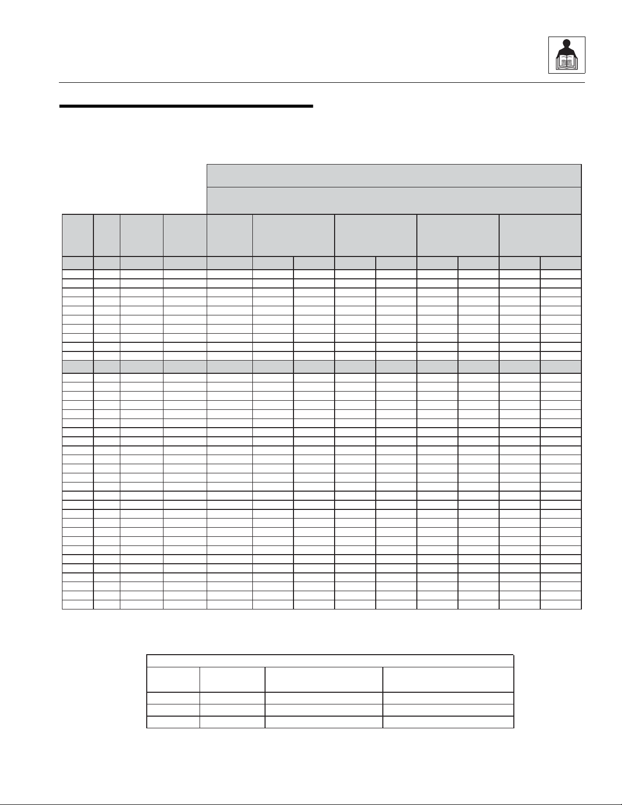
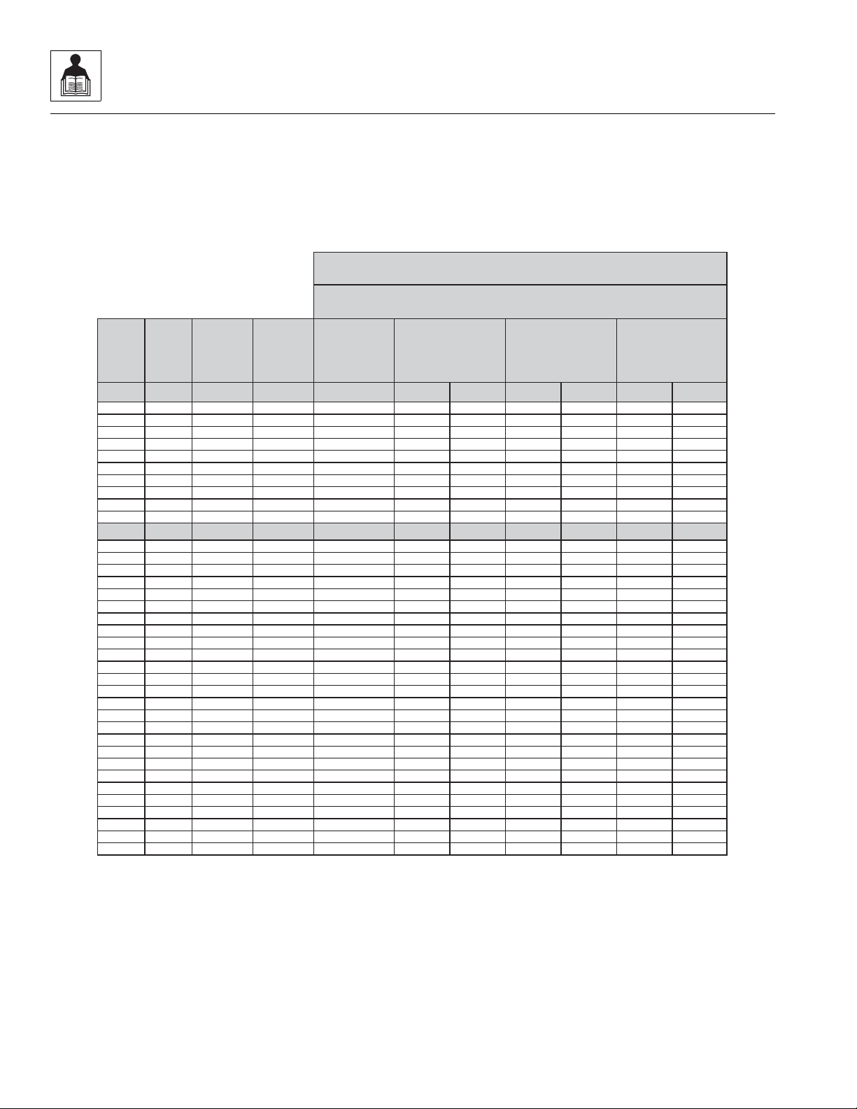
2.2 TORQUE CHARTS
REFERENCE JLG ANEROBIC THREAD LOCKING COMPOUND
Description
0100011
242
TM
Vibra-TITETM121
Medium Strength (Blue)
0100019
271
TM
Vibra-TITETM140
High Strength (Red)
0100071
262
TM
Vibra-TITETM131
Medium - High Strength (Red)
Size TPI Bolt Dia
Tensile
Stress Area
Clamp Load
In Sq In LB IN-LB [N.m] IN-LB [N.m] IN-LB [N.m] IN-LB [N.m]
4 40 0.1120 0.00604 380 8 0.9 6 0.7
48 0.1120 0.00661 420 9 1.0 7 0.8
6 32 0.1380 0.00909 580 16 1.8 12 1.4
40 0.1380 0.01015 610 18 2.0 13 1.5
8 32 0.1640 0.01400 900 30 3.4 22 2.5
36 0.1640 0.01474 940 31 3.5 23 2.6
10 24 0.1900 0.01750 1120 43 4.8 32 3.5
32 0.1900 0.02000 1285 49 5.5 36 4
1/4 20 0.2500 0.0318 2020 96 10.8 75 9 105 12
28 0.2500 0.0364 2320 120 13.5 86 10 135 15
In Sq In LB FT-LB [N.m] FT-LB [N.m] FT-LB [N.m] FT-LB [N.m]
5/16 18 0.3125 0.0524 3340 17 23 13 18 19 26 16 22
24 0.3125 0.0580 3700 19 26 14 19 21 29 17 23
3/8 16 0.3750 0.0775 4940 30 41 23 31 35 48 28 38
24 0.3750 0.0878 5600 35 47 25 34 40 54 32 43
7/16 14 0.4375 0.1063 6800 50 68 35 47 55 75 45 61
20 0.4375 0.1187 7550 55 75 40 54 60 82 50 68
1/2 13 0.5000 0.1419 9050 75 102 55 75 85 116 68 92
20 0.5000 0.1599 10700 90 122 65 88 100 136 80 108
9/16 12 0.5625 0.1820 11600 110 149 80 108 120 163 98 133
18 0.5625 0.2030 12950 120 163 90 122 135 184 109 148
5/8 11 0.6250 0.2260 14400 150 203 110 149 165 224 135 183
18 0.6250 0.2560 16300 170 230 130 176 190 258 153 207
3/4 10 0.7500 0.3340 21300 260 353 200 271 285 388 240 325
16 0.7500 0.3730 23800 300 407 220 298 330 449 268 363
7/8 9 0.8750 0.4620 29400 430 583 320 434 475 646 386 523
14 0.8750 0.5090 32400 470 637 350 475 520 707 425 576
1 8 1.0000 0.6060 38600 640 868 480 651 675 918 579 785
12 1.0000 0.6630 42200 700 949 530 719 735 1000 633 858
1 1/8 7 1.1250 0.7630 42300 800 1085 600 813 840 1142 714 968
12 1.1250 0.8560 47500 880 1193 660 895 925 1258 802 1087
1 1/4 7 1.2500 0.9690 53800 1120 1518 840 1139 1175 1598 1009 1368
12 1.2500 1.0730 59600 1240 1681 920 1247 1300 1768 1118 1516
1 3/8 6 1.3750 1.1550 64100 1460 1979 1100 1491 1525 2074 1322 1792
12 1.3750 1.3150 73000 1680 2278 1260 1708 1750 2380 1506 2042
1 1/2 6 1.5000 1.4050 78000 1940 2630 1460 1979 2025 2754 1755 2379
12 1.5000 1.5800 87700 2200 2983 1640 2224 2300 3128 1974 2676
Values for ZincYellow Chromate Fasteners
SAE GRADE 5 BOLTS & GRADE 2 NUTS
Torque
(Dry)
Torque
Lubricated
3. *ASSEMBLYUSES HARDENED WASHER
NOTES: 1. THESE TORQUE VALUES DONOT APPLY TO CADMIUM PLATED FASTENERS
2. ALL TORQUEVALUESARE STATICTORQUE MEASUREDPER STANDARD AUDIT METHODS TOLERANCE= ±10%
MY4510J
JLG P/N Loctite® P/N
ND Industries P/N
Torque
Loctite® 262™
OR
Vibra-TITE™ 131
Torque
Loctite® 242™ or 271™
OR
Vibra-TITE™ 111 or 140
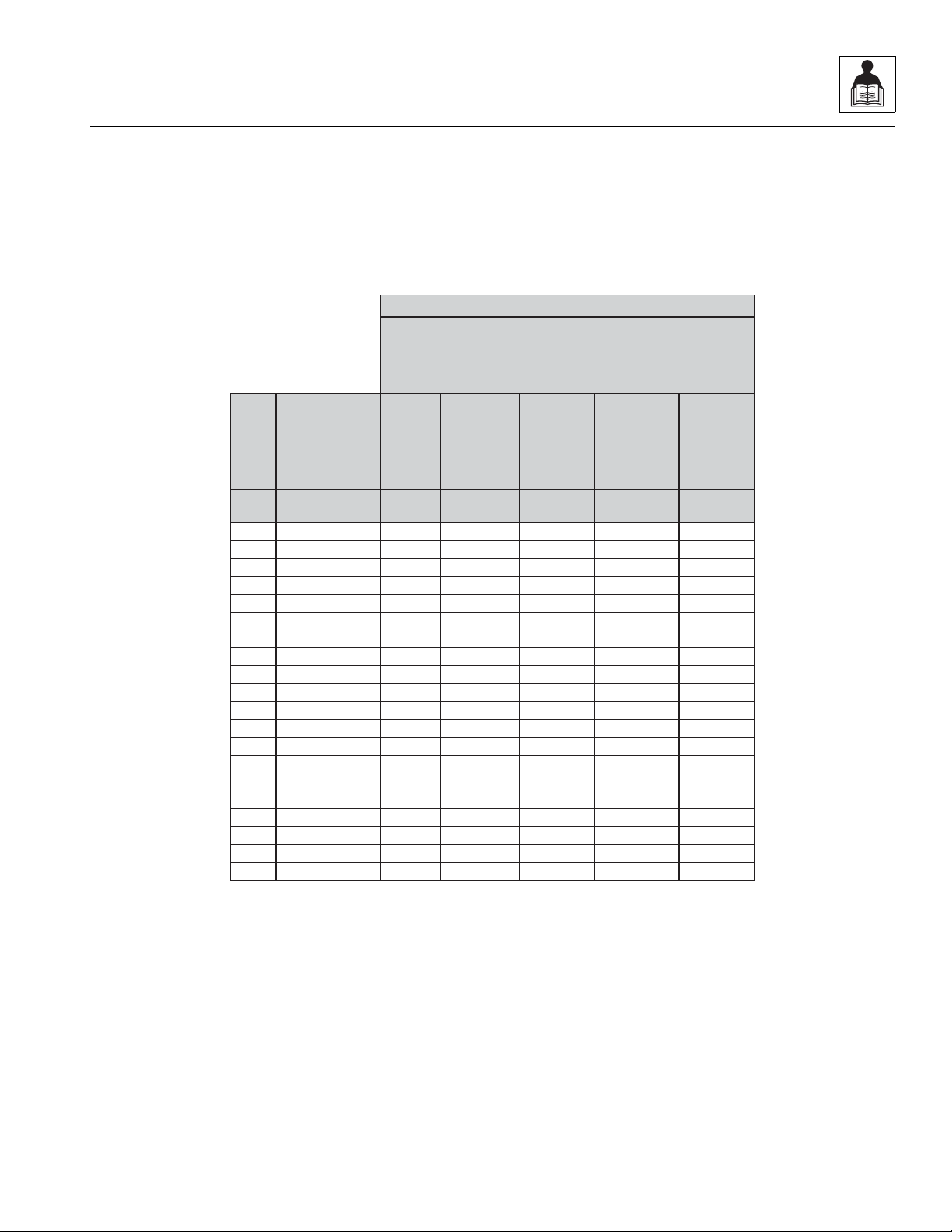
2.2.1 SAE Fastener Torque Chart
General Information and Specifications
3508PS, 3509PS, 3512PS, 3513PS, 4008PS, 4009PS, 4012PS, 4013PS, 4017PS, 40.8, 40.9
2-3

General Information and Specifications
Size TPI Bolt Dia
Tensile
Stress Area
Clamp Load
In Sq In
4 40 0.1120 0.00604
48 0.1120 0.00661
6 32 0.1380 0.00909
40 0.1380 0.01015
8 32 0.1640 0.01400
36 0.1640 0.01474
10 24 0.1900 0.01750
32 0.1900 0.02000
1/4 20 0.2500 0.0318
28 0.2500 0.0364
In Sq In
5/16 18 0.3125 0.0524
24 0.3125 0.0580
3/8 16 0.3750 0.0775
24 0.3750 0.0878
7/16 14 0.4375 0.1063
20 0.4375 0.1187
1/2 13 0.5000 0.1419
20 0.5000 0.1599
9/16 12 0.5625 0.1820
18 0.5625 0.2030
5/8 11 0.6250 0.2260
18 0.6250 0.2560
3/4 10 0.7500 0.3340
16 0.7500 0.3730
7/8 9 0.8750 0.4620
14 0.8750 0.5090
1 8 1.0000 0.6060
12 1.0000 0.6630
1 1/8 7 1.1250 0.7630
12 1.1250 0.8560
1 1/4 7 1.2500 0.9690
12 1.2500 1.0730
1 3/8 6 1.3750 1.1550
12 1.3750 1.3150
1 1/2 6 1.5000 1.4050
12 1.5000 1.5800
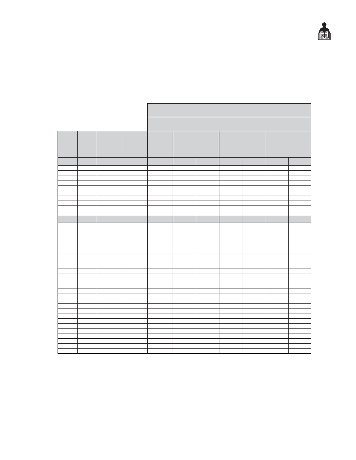
Values for Zinc Yellow Chromate Fasteners
3. *ASSEMBLY USES HARDENED WASHER
NOTES: 1. THESE TORQUEVALUES DO NOTAPPLYTO CADMIUM PLATED FASTENERS
2. ALL TORQUE VALUESARE STATICTORQUE MEASURED PER STANDARD AUDIT METHODS TOLERANCE = ±10%
LB IN-LB [N.m] IN-LB [N.m] IN-LB [N.m]
1320 43 5
1580 60 7
1800 68 8
2860 143 16 129 15
3280 164 19 148 17
LB FT-LB [N.m] FT-LB [N.m] FT-LB [N.m
4720 25 35 20 25 20 25
5220 25 35 25 35 20 25
7000 45 60 40 55 35 50
7900 50 70 45 60 35 50
9550 70 95 65 90 50 70
10700 80 110 70 95 60 80
12750 105 145 95 130 80 110
14400 120 165 110 150 90 120
16400 155 210 140 190 115 155
18250 170 230 155 210 130 175
20350 210 285 190 260 160 220
23000 240 325 215 290 180 245
30100 375 510 340 460 280 380
33600 420 570 380 515 315 430
41600 605 825 545 740 455 620
45800 670 910 600 815 500 680
51500 860 1170 770 1045 645 875
59700 995 1355 895 1215 745 1015
68700 1290 1755 1160 1580 965 1310
77000 1445 1965 1300 1770 1085 1475
87200 1815 2470 1635 2225 1365 1855
96600 2015 2740 1810 2460 1510 2055
104000 2385 3245 2145 2915 1785 2430
118100 2705 3680 2435 3310 2030 2760
126500 3165 4305 2845 3870 2370 3225
142200 3555 4835 3200 4350 2665 3625
K=.18
K=0.15
SAE GRADE 8 (HEX HD) BOLTS & GRADE 8 NUTS*
Torque
(Dry orLoctite® 263)
K= 0.20
MY4660J
Torque
Loctite® 262™
OR
Vibra-TITE™ 131
Torque
Loctite® 242™ or 271™
OR
Vibra-TITE™ 111 or 140
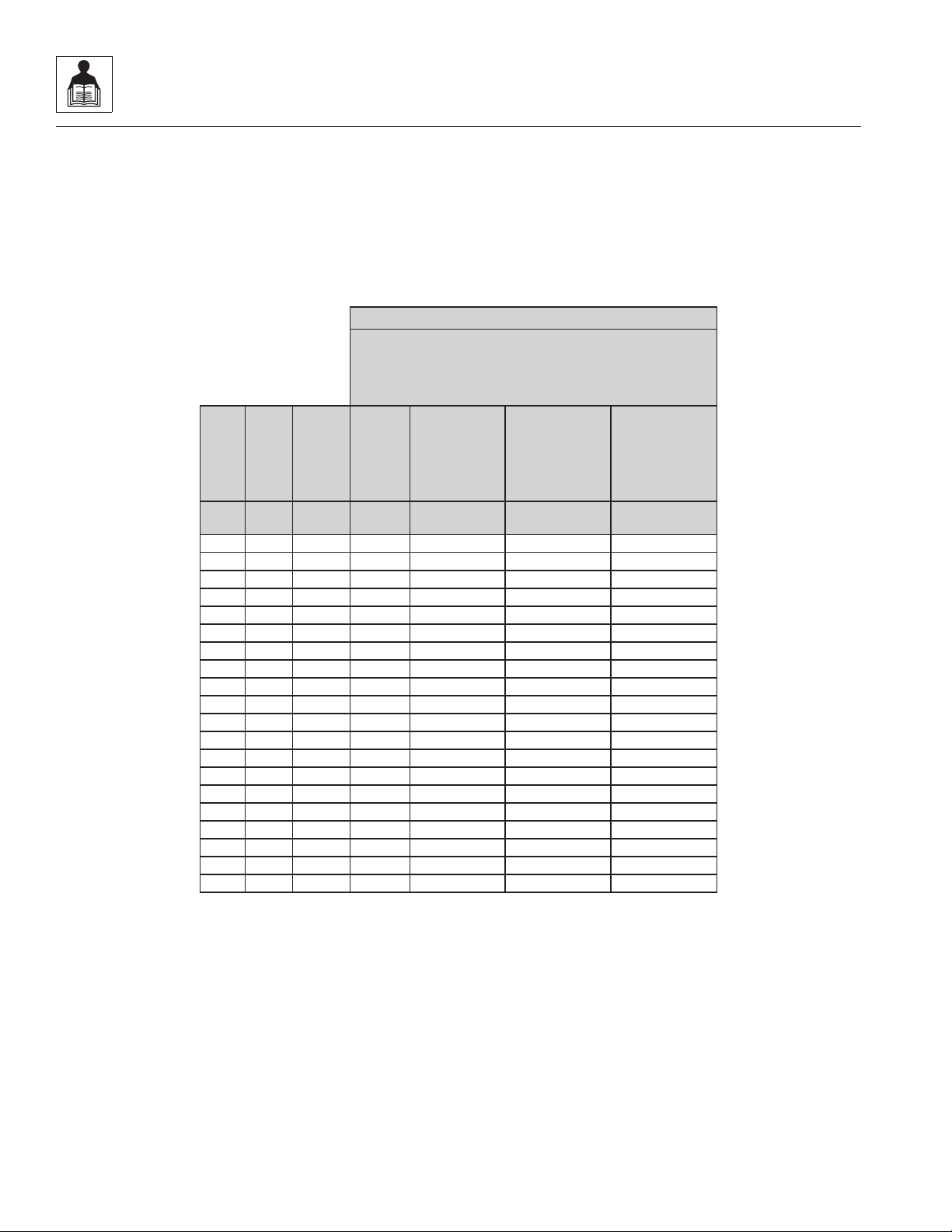
2.2.1 SAE Fastener Torque Chart
(Continued)
2-4
3508PS, 3509PS, 3512PS, 3513PS, 4008PS, 4009PS, 4012PS, 4013PS, 4017PS, 40.8, 40.9
General Information and Specifications
Size TPI Bolt Dia
Tensile
Stress Area
Clamp Load
See Note4
In Sq In LB IN-LB [N.m] IN-LB [N.m] IN-LB [N.m]
4 40 0.1120 0.00604
48 0.1120 0.00661
6 32 0.1380 0.00909
40 0.1380 0.01015
8 32 0.1640 0.01400
36 0.1640 0.01474
10 24 0.1900 0.01750
32 0.1900 0.02000
1/4 20 0.2500 0.0318 2860 122 14 114 13
28 0.2500 0.0364 3280 139 16 131 15
In Sq In LB FT-LB [N.m] FT-LB [N.m] FT-LB [N.m]
5/16 18 0.3125 0.0524 4720 20 25 20 25 20 25
24 0.3125 0.0580 5220 25 35 20 25 20 25
3/8 16 0.3750 0.0775 7000 35 50 35 50 35 50
24 0.3750 0.0878 7900 40 55 40 55 35 50
7/16 14 0.4375 0.1063 9550 60 80 55 75 50 70
20 0.4375 0.1187 10700 65 90 60 80 60 80
1/2 13 0.5000 0.1419 12750 90 120 85 115 80 110
20 0.5000 0.1599 14400 100 135 95 130 90 120
9/16 12 0.5625 0.1820 16400 130 175 125 170 115 155
18 0.5625 0.2030 18250 145 195 135 185 130 175
5/8 11 0.6250 0.2260 20350 180 245 170 230 160 220
18 0.6250 0.2560 23000 205 280 190 260 180 245
3/4 10 0.7500 0.3340 30100 320 435 300 410 280 380
16 0.7500 0.3730 33600 355 485 335 455 315 430
7/8 9 0.8750 0.4620 41600 515 700 485 660 455 620
14 0.8750 0.5090 45800 570 775 535 730 500 680
1 8 1.0000 0.6060 51500 730 995 685 930 645 875
12 1.0000 0.6630 59700 845 1150 795 1080 745 1015
1 1/8 7 1.1250 0.7630 68700 1095 1490 1030 1400 965 1310
12 1.1250 0.8560 77000 1225 1665 1155 1570 1085 1475
1 1/4 7 1.2500 0.9690 87200 1545 2100 1455 1980 1365 1855
12 1.2500 1.0730 96600 1710 2325 1610 2190 1510 2055
1 3/8 6 1.3750 1.1550 104000 2025 2755 1905 2590 1785 2430
12 1.3750 1.3150 118100 2300 3130 2165 2945 2030 2760
1 1/2 6 1.5000 1.4050 126500 2690 3660 2530 3440 2370 3225
12 1.5000 1.5800 142200 3020 4105 2845 3870 2665 3625
4. CLAMPLOAD LISTEDFOR SHCS IS SAMEAS GRADE 8 OR CLASS 10.9 AND DOES NOT REPRESENT FULL STRENGTH
CAPABILITYOF SHCS.IF HIGHER LOAD IS REQUIRED, ADDITIONALTESTING ISREQUIRED.
SOCKET HEAD CAP SCREWS
Magni Coating*
Torque
(Dry) K = .17
K=0.16
K=0.15
2. ALL TORQUE VALUESARE STATICTORQUE MEASURED PER STANDARD AUDIT METHODS TOLERANCE = ±10%
NOTES: 1.THESE TORQUE VALUESDO NOTAPPLY TOCADMIUM PLATED FASTENERS
*3. ASSEMBLY USES HARDENED WASHER OR FASTENER IS PLACED AGAINST PLATEDSTEEL OR RAWALUMINUM
MY4670J
Torque
Loctite® 262™
OR
Vibra-TITE™ 131
Torque
Loctite® 242™ or 271™
OR
Vibra-TITE™ 111 or 140
OR Precoat 85®
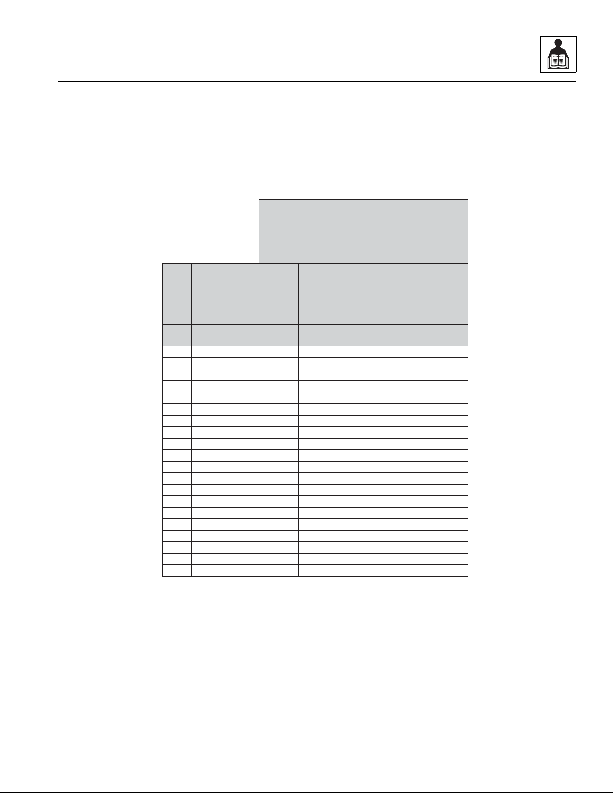
2.2.1 SAE Fastener Torque Chart
(Continued)
3508PS, 3509PS, 3512PS, 3513PS, 4008PS, 4009PS, 4012PS, 4013PS, 4017PS, 40.8, 40.9
2-5
General Information and Specifications
Size TPI Bolt Dia
Tensile
Stress Area
Clamp Load
See Note4
In Sq In LB IN-LB [N.m] IN-LB [N.m] IN-LB [N.m]
4 40 0.1120 0.00604
48 0.1120 0.00661
6 32 0.1380 0.00909
40 0.1380 0.01015
8 32 0.1640 0.01400
36 0.1640 0.01474
10 24 0.1900 0.01750
32 0.1900 0.02000
1/4 20 0.2500 0.0318 2860 143 16 129 15
28 0.2500 0.0364 3280 164 19 148 17
In Sq In LB FT-LB [N.m] FT-LB [N.m] FT-LB [N.m]
5/16 18 0.3125 0.0524 4720 25 35 20 25 20 25
24 0.3125 0.0580 5220 25 35 25 35 20 25
3/8 16 0.3750 0.0775 7000 45 60 40 55 35 50
24 0.3750 0.0878 7900 50 70 45 60 35 50
7/16 14 0.4375 0.1063 9550 70 95 65 90 50 70
20 0.4375 0.1187 10700 80 110 70 95 60 80
1/2 13 0.5000 0.1419 12750 105 145 95 130 80 110
20 0.5000 0.1599 14400 120 165 110 150 90 120
9/16 12 0.5625 0.1820 16400 155 210 140 190 115 155
18 0.5625 0.2030 18250 170 230 155 210 130 175
5/8 11 0.6250 0.2260 20350 210 285 190 260 160 220
18 0.6250 0.2560 23000 240 325 215 290 180 245
3/4 10 0.7500 0.3340 30100 375 510 340 460 280 380
16 0.7500 0.3730 33600 420 570 380 515 315 430
7/8 9 0.8750 0.4620 41600 605 825 545 740 455 620
14 0.8750 0.5090 45800 670 910 600 815 500 680
1 8 1.0000 0.6060 51500 860 1170 775 1055 645 875
12 1.0000 0.6630 59700 995 1355 895 1215 745 1015
1 1/8 7 1.1250 0.7630 68700 1290 1755 1160 1580 965 1310
12 1.1250 0.8560 77000 1445 1965 1300 1770 1085 1475
1 1/4 7 1.2500 0.9690 87200 1815 2470 1635 2225 1365 1855
12 1.2500 1.0730 96600 2015 2740 1810 2460 1510 2055
1 3/8 6 1.3750 1.1550 104000 2385 3245 2145 2915 1785 2430
12 1.3750 1.3150 118100 2705 3680 2435 3310 2030 2760
1 1/2 6 1.5000 1.4050 126500 3165 4305 2845 3870 2370 3225
12 1.5000 1.5800 142200 3555 4835 3200 4350 2665 3625
4. CLAMPLOAD LISTEDFOR SHCS IS SAMEAS GRADE 8 OR CLASS 10.9 AND DOES NOT REPRESENT FULL STRENGTH
CAPABILITYOF SHCS.IF HIGHER LOAD IS REQUIRED, ADDITIONALTESTING ISREQUIRED.
SOCKET HEAD CAP SCREWS
Torque
(Dry)
K=.20
Torque
(Loctite® 242TMor 271
TM
OR Vibra-TITETM111 or
140 ORPrecoat 85®
K=0.18
Zinc Yellow Chromate Fasteners*
2. ALL TORQUE VALUESARE STATICTORQUE MEASURED PER STANDARD AUDIT METHODS TOLERANCE = ±10%
NOTES: 1.THESE TORQUE VALUESDO NOTAPPLY TOCADMIUM PLATED FASTENERS
*3. ASSEMBLY USES HARDENED WASHER OR FASTENER IS PLACED AGAINST PLATEDSTEEL OR RAWALUMINUM
Torque
(Loctite® 262
TM
or Vibra-
TITE
TM
131)
K=0.15
MY4680J
2.2.1 SAE Fastener Torque Chart
(Continued)
2-6
3508PS, 3509PS, 3512PS, 3513PS, 4008PS, 4009PS, 4012PS, 4013PS, 4017PS, 40.8, 40.9
2.2.2 Metric Fastener Torque Chart
Size PITCH
Tensile
Stress
Area
Clamp
Load
Torque
(Dry orLoctite®
263
TM
)
Torque
(Lub)
Sq mm KN [N.m] [N.m] [N.m] [N.m]
3 0.5 5.03 2.19 1.3 1.0 1.2 1.4
3.5 0.6 6.78 2.95 2.1 1.6 1.9 2.3
4 0.7 8.78 3.82 3.1 2.3 2.8 3.4
5 0.8 14.20 6.18 6.2 4.6 5.6 6.8
6 1 20.10 8.74 11 7.9 9.4 12
7 1 28.90 12.6 18 13 16 19
8 1.25 36.60 15.9 26 19 23 28
10 1.5 58.00 25.2 50 38 45 55
12 1.75 84.30 36.7 88 66 79 97
14 2 115 50.0 140 105 126 154
16 2 157 68.3
219 164 197 241
18 2.5 192 83.5 301 226 271 331
20 2.5 245 106.5 426 320 383 469
22 2.5 303 132.0 581 436 523 639
24 3 353 153.5 737 553 663 811
27 3 459 199.5 1080 810 970 1130
30 3.5 561 244.0 1460 1100 1320 1530
33 3.5 694 302.0 1990 1490 1790 2090
36 4 817 355.5 2560 1920 2300 2690
42 4.5 1120 487.0 4090 3070 3680 4290
4. CLAMPLOAD LISTEDFOR SHCS IS SAMEAS GRADE 8 OR CLASS 10.9 AND DOES NOT
REPRESENT FULL STRENGTH CAPABILITY OF SHCS. IFHIGHER LOAD IS REQUIRED,
ADDITIONAL TESTING IS REQUIRED.
*3. ASSEMBLY USES HARDENED WASHER OR FASTENER IS PLACED AGAINST PLATED
STEEL OR RAWALUMINUM
Values for Zinc Yellow Chromate Fasteners
CLASS 8.8 METRIC BOLTS
CLASS 8 METRIC NUTS
NOTES: 1.THESE TORQUE VALUESDO NOTAPPLY TOCADMIUM PLATED FASTENERS
2. ALL TORQUE VALUESARE STATICTORQUE MEASURED PER STANDARD AUDIT
METHODS TOLERANCE = ±10%
MY4690J
Torque
Loctite® 262™
OR
Vibra-TITE™ 131
Torque
Loctite®
242™ or 271™
OR
Vibra-TITE™
111 or 140
General Information and Specifications
3508PS, 3509PS, 3512PS, 3513PS, 4008PS, 4009PS, 4012PS, 4013PS, 4017PS, 40.8, 40.9
2-7
General Information and Specifications
Size PITCH
Tensile
Stress
Area
Clamp
Load
K =0.20
K= 0.18
K=0.15
Sq mm KN [N.m] [N.m] [N.m]
3 0.5 5.03 3.13
3.5 0.6 6.78 4.22
4 0.7 8.78 5.47
5 0.8 14.20 8.85
6 1 20.10 12.5
7 1 28.90 18.0 25.2 22.7 18.9
8 1.25 36.60 22.8 36.5 32.8 27.4
10 1.5 58.00 36.1 70 65 55
12 1.75 84.30 52.5 125 115 95
14 2 115 71.6 200 180 150
16 2 157 97.8
315 280 235
18 2.5 192 119.5 430 385 325
20 2.5 245 152.5 610 550 460
22 2.5 303 189.0 830 750 625
24 3 353 222.0 1065 960 800
27 3 459 286.0 1545 1390 1160
30 3.5 561 349.5 2095 1885 1575
33 3.5 694 432.5 2855 2570 2140
36 4 817 509.0 3665 3300 2750
42 4.5 1120 698.0 5865 5275 4395
Values for Zinc Yellow Chromate Fasteners
CLASS 10.9 METRIC BOLTS
CLASS 10 METRIC NUTS
CLASS 12.9 SOCKET HEAD CAP SCREWS M3 - M5*
4. CLAMPLOAD LISTEDFOR SHCS IS SAMEAS GRADE 8 OR CLASS 10.9 AND DOES NOT
REPRESENT FULL STRENGTH CAPABILITY OF SHCS. IFHIGHER LOAD IS REQUIRED,
ADDITIONAL TESTING IS REQUIRED.
*3. ASSEMBLY USES HARDENED WASHER OR FASTENER IS PLACED AGAINST PLATED
STEEL OR RAWALUMINUM
NOTES: 1.THESE TORQUE VALUESDO NOTAPPLY TOCADMIUM PLATED FASTENERS
2. ALL TORQUE VALUESARE STATICTORQUE MEASURED PER STANDARD AUDIT
METHODS TOLERANCE = ±10%
MY4700J
Torque
Loctite® 262™
OR
Vibra-TITE™ 131
Torque Dry
or
Loctite® 263™
Torque
Lube OR Loctite®
242™ or 271™
OR
Vibra-TITE™
111 or 140
2.2.2 Metric Fastener Torque Chart
(Continued)
2-8
3508PS, 3509PS, 3512PS, 3513PS, 4008PS, 4009PS, 4012PS, 4013PS, 4017PS, 40.8, 40.9
2.2.2 Metric Fastener Torque Chart
Size PITCH
Tensile
Stress
Area
Clamp Load
See Note4
K=.17
K=.16
K=.15
Sq mm kN [N.m] [N.m] [N.m]
3 0.5 5.03
3.5 0.6 6.78
4 0.7 8.78
5 0.8 14.20
6 1 20.10 12.5 13 12 11
7 1 28.90 18.0 21 20 19
8 1.25 36.60 22.8 31 29 27
10 1.5 58.00 36.1 61 58 54
12 1.75 84.30 52.5 105 100 95
14 2 115 71.6 170 160 150
16 2 157
97.8 265 250 235
18 2.5 192 119.5 365 345 325
20 2.5 245 152.5 520 490 460
22 2.5 303 189.0 705 665 625
24 3 353 220.0 900 845 790
27 3 459 286.0 1315 1235 1160
30 3.5 561 349.5 1780 1680 1575
33 3.5 694 432.5 2425 2285 2140
36 4 817 509.0 3115 2930 2750
42 4.5 1120 698.0 4985 4690 4395
CLASS 12.9 SOCKET HEAD CAP SCREWS
M6 ANDABOVE*
4. CLAMPLOAD LISTEDFOR SHCS IS SAMEAS GRADE 8 OR CLASS 10.9 AND DOES NOT
REPRESENT FULL STRENGTH CAPABILITY OF SHCS. IFHIGHER LOAD IS REQUIRED,
ADDITIONAL TESTING IS REQUIRED.
*3. ASSEMBLY USES HARDENED WASHER OR FASTENER IS PLACED AGAINST PLATED
STEEL OR RAWALUMINUM
NOTES: 1.THESE TORQUE VALUESDO NOTAPPLY TOCADMIUM PLATED FASTENERS
2. ALL TORQUE VALUESARE STATICTORQUE MEASURED PER STANDARD AUDIT
METHODS TOLERANCE = ±10%
Magni Coating*
MY4710J
Torque
Loctite® 262™
OR
Vibra-TITE™ 131
Torque
Lube OR Loctite®
242™ or 271™
OR
Vibra-TITE™
111 or 140
Torque Dry
or
Loctite® 263™
(Continued)
General Information and Specifications
3508PS, 3509PS, 3512PS, 3513PS, 4008PS, 4009PS, 4012PS, 4013PS, 4017PS, 40.8, 40.9
2-9

General Information and Specifications
2.2.3 Hydraulic Hose Torque Chart
O-Ring Face Seal & JIC Torque Chart
Size ORFS JIC Flats Method
4
6
8
10
12
16
20
24
13 lb-ft
(18 Nm)
23 lb-ft
(31 Nm)
40 lb-ft
(54 Nm)
60 lb-ft
(81 Nm)
74 lb-ft
(100 Nm)
115 lb-ft
(156 Nm)
170 lb-ft
(230 Nm)
200 lb-ft
(271 Nm)
13 lb-ft
(18 Nm)
23 lb-ft
(31 Nm)
40 lb-ft
(54 Nm)
60 lb-ft
(81 Nm)
85 lb-ft
(115 Nm)
115 lb-ft
(156 Nm)
170 lb-ft
(230 Nm)
200 lb-ft
(271 Nm)
1.5 to 1.75
1 to 1.5
1.5 to 1.75
1.5 to 1.75
1.0 to 1.5
0.75 to 1.0
0.75 to 1.0
0.75 to 1.0
Flats Method:
1. If equipped, lubricate o-ring with hydraulic oil. Hand
tighten the swivel nut until no lateral movement of
the swivel nut can be detected. Average hand torque
is 3 lb-ft (4 Nm).
2. Mark a dot on one of the swivel nut flats and another
dot in line on the hex of the adapter it’s connecting
to.
3. Use the double wrench method while tightening to
avoid hose twist.
4. After the connection has been properly tightened,
mark a straight line across the connecting parts, not
covering the dots indicating that the con necti on has
been properly tightened.
32 N/A
270 lb-ft
(366 Nm)
0.75 to 1.0
Note: By definition the “Flats Method“ will contain some
variance. Use the “Flats Method” only when accessibility
with a torque wrench is not possible.
Torque Wrench:
1. Identify the appropriate application and refer to the
above chart for the correct torque value.
2. If equipped, lubricate o-ring with hydraulic oil. Hand
tighten the swivel nut until no lateral movement of
the swivel nut can be detected. Average hand torque
is 3 lb-ft (4 Nm).
3. Use the double wrench method while tightening to
avoid hose twist.
4. Torque wrench must be held at the center of the grip.
Apply constant force until it clicks.
5. After the connection has been properly tightened,
mark a straight line across the connecting parts
indicating that the connection has been properly
tightened.
2-10
3508PS, 3509PS, 3512PS, 3513PS, 4008PS, 4009PS, 4012PS, 4013PS, 4017PS, 40.8, 40.9

General Information and Specifications
2.3 SPECIFICATIONS
2.3.1 Travel Speeds
Function Speed
First Gear 5 km/h (3.1 mph)
Second Gear 10 km/h (6.2 mph)
Third Gear 25 km/h (15.5 mph)
Fourth Gear (Turbo Only) 35 km/h (21.7 mph)
2.3.2 Hydraulic Cylinder Performance Specifications
Note: Machine with no load, engine at full throttle, hydraulic oil above 130° F (54° C) minimum, engine at operating
temperature.
Function
7M 8M 9M 12M 13M 17M
Boom Extend 11,60 11,60 13,30 14,03 16,88 23,0
Boom Retract 83 9,83 11,27 12,48 15,02 18,0
Boom Lift 8,28 9,43 14,0 12,32 14,00 15,5
Boom Lower 5,63 6,41 9,65 8,49 9,65 10,0
Attachment Tilt - UP 9,78 9,78 9,78 9,78 9,78 4,5
Attachment Tilt - DOWN 4,50 4,50 4,50 4,50 4,50 9,8
Outrigger - UP N/A N/A N/A 2,93 2,93 8,7
Outrigger - DOWN N/A N/A N/A 2,19 2,19 6,4
Frame Level 11,0 11,0 11,0 11,0 11,0 N/A
Approximate Times (sec.)
2.3.3 Platform Hydraulic Performance Specifications
Function
Platform Lift 31 39
Platform Lower 31 39
Approximate Times (sec.)
13M 17M
Platform Extend 19 27
Platform Retract 19 27
Platform Rotate 180° 14 14
3508PS, 3509PS, 3512PS, 3513PS, 4008PS, 4009PS, 4012PS, 4013PS, 4017PS, 40.8, 40.9
2-11

General Information and Specifications
2.3.4 Electrical System
Note: Refer to Section 9.6, “Fuses and Relays,” for more information.
Battery
Type, Rating 12V DC, Negative (-) Ground, Limited Maintenance,
Wet Charged
Quantity 1 (100 Ah) (C
20
)
Reserve Capacity CCA @ -18° C: 880 EN
Group/Series DIN 600,38
Alternator 12V, 85 Amps
Starter 12V, 3,2 KW Type EV (Gear Reduction)
2.3.5 Engine Performance Specifications
Note: Engine manufacturer's maximum “high idle” setting is lockwired and sealed. DO NOT disturb this setting.
Description
Engine Make/Model Perkins 1004-40T
Low Idle 925 RPM ±50 RPM
High Idle 2340 RPM ±50 RPM
Horsepower 80,4 BHP/60 KW @ 2200 rpm
Fuel Delivery Fuel Injection
Air Cleaner Dry Type, Replaceable Primary and Safety Elements
2.3.6 Tires
Note: Standard wheel lug nut torque is 500 Nm (369 lb-ft).
Size Tire Type Minimum Ply Fill Type Pressure
405/70-24 MPT01 AG 14 Ply Pneumatic 4,0 Bar (58 psi)
405/70-24 MPT04 CONST 14 Ply Pneumatic 4,0 Bar (58 psi)
405/70-24 MPT01 AG (4017PS only) 14 Ply Pneumatic 4,5 Bar (65 psi)
405/70-24 MPT04 CONST (4017PS only) 14 Ply Pneumatic 4,5 Bar (65 psi)
2-12
3508PS, 3509PS, 3512PS, 3513PS, 4008PS, 4009PS, 4012PS, 4013PS, 4017PS, 40.8, 40.9

General Information and Specifications
2.4 FLUIDS, LUBRICANTS AND CAPACITIES
Engine Crankcase Oil
Capacity w/Filter Change 8,5 L (9 qt)
Oil Type
3508PS, 3509PS, 3512PS, 3513PS, 4008PS,
4009PS, 4012PS, 4013PS & 4017PS
15W-40 CH
40.8 & 40.9 DF Super ENGINE OIL 15W-40
Fuel Tank
Capacity 140 L (37 gal)
Type of Fuel #2 Diesel
Cooling System
System Capacity 20 L (5 gal)
Type of Fluid 50/50 mix of ethylene glycol and water
Hydraulic System
System Capacity (8, 9M, 40.8 & 40.9) 220 L (58 gal)
System Capacity (12, 13 & 17M) 240 L (63 gal)
Reservoir Capacity to FULL Mark 160 L (42 gal)
Type of Fluid
3508PS, 3509PS, 3512PS, 3513PS, 4008PS,
4009PS, 4012PS, 4013PS & 4017PS
Mobilfluid 424
®
(ISO 46)
40.8 & 40.9 DF UTTO Tractor Hydraulic Fluid
Transmission
Capacity with Filter Change 12,9 L (13.6 qt)
Type of Fluid
3508PS, 3509PS, 3512PS, 3513PS, 4008PS,
4009PS, 4012PS, 4013PS & 4017PS
Mobilfluid 424
®
(ISO 46)
40.8 & 40.9 DF UTTO Tractor Hydraulic Fluid
Transfer Case
Capacity 1,4 L (1.5 qt)
Type of Fluid
3508PS, 3509PS, 3512PS, 3513PS, 4008PS,
4009PS, 4012PS, 4013PS & 4017PS
Mobilfluid 424
®
(ISO 46)
40.8 & 40.9 DF UTTO Tractor Hydraulic Fluid
3508PS, 3509PS, 3512PS, 3513PS, 4008PS, 4009PS, 4012PS, 4013PS, 4017PS, 40.8, 40.9
2-13

General Information and Specifications
Axles
Differential Housing Capacity - Front 8,0 L (8.5 qt)
Differential Housing Capacity - Rear 7,3 L (7.7 qt)
Wheel End Capacity - Front 1,9 L (2.0 qt)
Wheel End Capacity - Rear 1,4 L (1.5 qt)
Type of Fluid
3508PS, 3509PS, 3512PS, 3513PS, 4008PS,
4009PS, 4012PS, 4013PS & 4017PS
Mobilfluid 424
®
(ISO 46)
40.8 & 40.9 DF UTTO Tractor Hydraulic Fluid
Brake System
System Capacity 1,0 L (1.1 qt)
Type of Oil
3508PS, 3509PS, 3512PS, 3513PS, 4008PS,
4009PS, 4012PS, 4013PS & 4017PS
Dexron II or III ATF
40.8 & 40.9 DONAX TA
Air Conditioning System (if equipped)
System Capacity 2,05 kg (4.5 lb)
Type of Refrigerant R-134a Tetrafluoroethane
Type of Lubricant PAG-oil SP-20, TXV System
Quantity of Lubricant 68,3 ccm (2.3 oz)
2-14
3508PS, 3509PS, 3512PS, 3513PS, 4008PS, 4009PS, 4012PS, 4013PS, 4017PS, 40.8, 40.9
General Information and Specifications
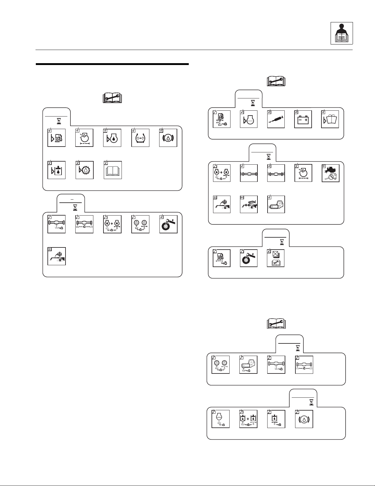
MZ1671
Air Filter
Check Fuel
Level
Check Engine
Oil Level
Check
Transmission
Oil Level
Check Hydraulic
Oil Level
Check Tire
Condition &
Pressure
Check Brake
Fluid Level
8
EVERY
Additional Checks -
Operation &
Safety Manual
Check Wheel
Lug Nut
Torque
LB/FT (Nm)
Change
Axle Oil
Change Wheel
End Oil
50
1
st
Check Boom
Chain & Tension
(17M Only)
Change Engine
Oil & Filter
Change
Transmission
Oil & Filter
MZ1681
250
EVERY
Check Axle
Oil Level
Check Wheel
End Oil Levels
Air Filter
Vacuator
Valve
Check
Fan Belt
Check Boom
Chain & Tension
(17M Only)
Check Boom
Wear Pads
Check Transfer
Case Oil Level
Change Engine
Oil and
Filter
Check LSI
Calibration
500
EVERY
Check Wheel
Lug Nut
Torque
LB/FT (Nm)
Change Fuel
Filter
50
EVERY
Drain Fuel/
Water
Separator
Check Engine
Coolant Level
Lubrication
Schedule
Check
Battery
Check Washer
Fluid Level
MZ1690
1500
EVERY
Change
Engine Coolant
Change
Hydraulic
Fluid & Filters
Change
Hydraulic Tank
Breather
Change
Brake Fluid
1000
EVERY
Change
Axle Oil
Change Wheel
End Oil
Change
Transmission
Oil & Filter
Change
Transfer Case
Oil
2.5 MAINTENANCE SCHEDULES
2.5.1 8 & 1st 50 Hour Maintenance Schedule
2.5.2 50, 250 & 500 Hour Maintenance Schedule
3508PS, 3509PS, 3512PS, 3513PS, 4008PS, 4009PS, 4012PS, 4013PS, 4017PS, 40.8, 40.9
2.5.3 1000 & 1500 Hour Maintenance Schedule
2-15
General Information and Specifications
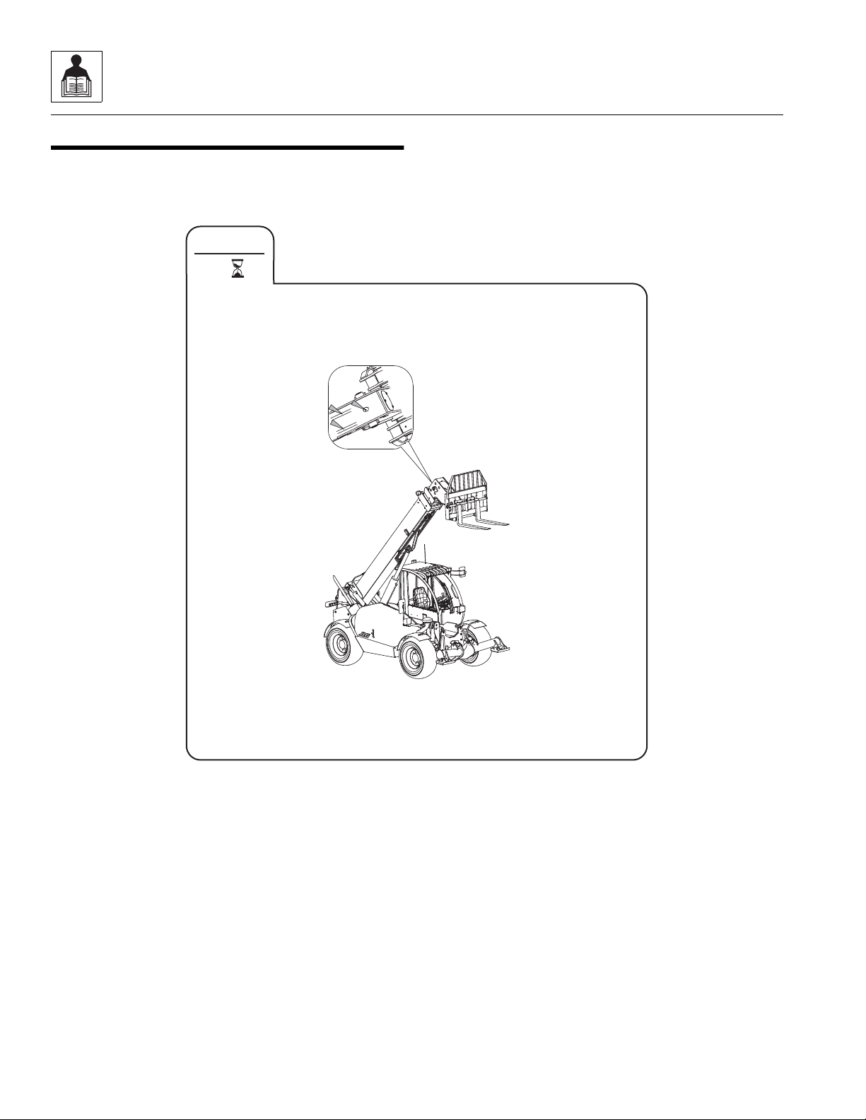
EVERY
8
OZ2260
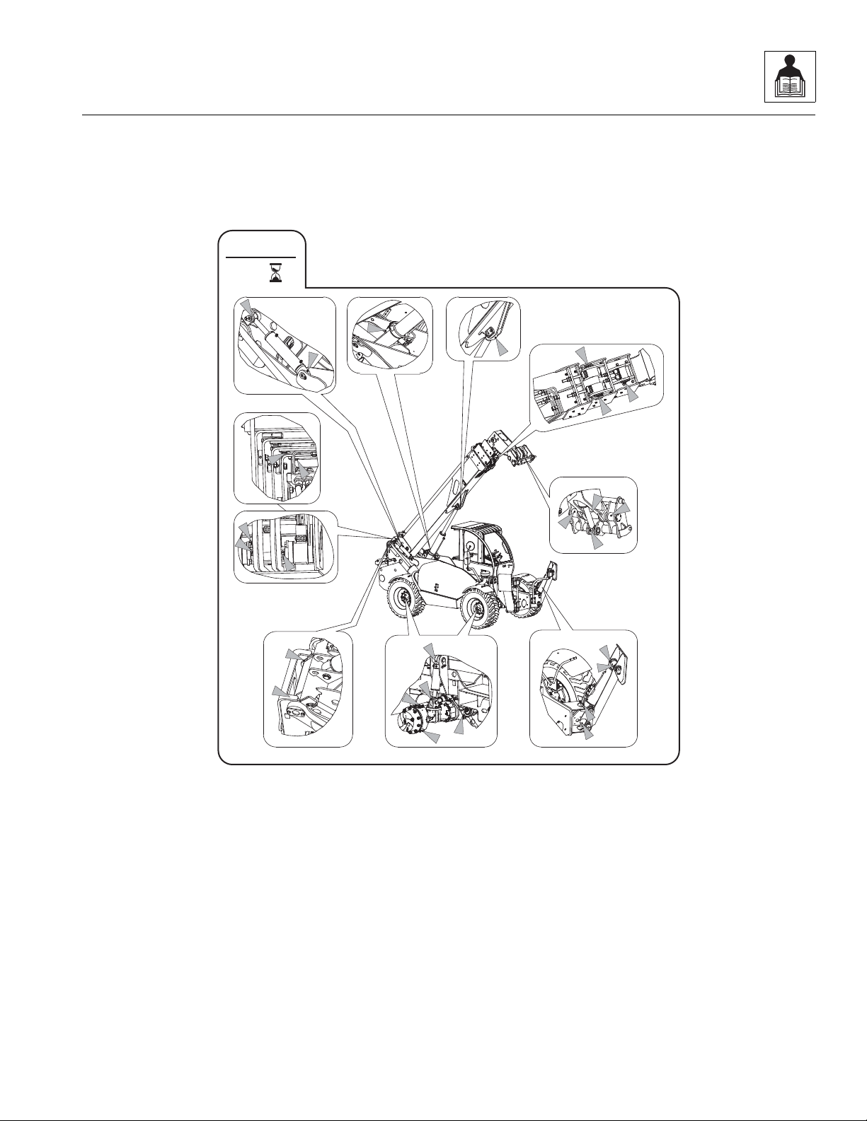
2.6 LUBRICATION SCHEDULES
2.6.1 8 Hour Lubrication Schedule
8, 9, 12 & 13M
2-16
3508PS, 3509PS, 3512PS, 3513PS, 4008PS, 4009PS, 4012PS, 4013PS, 4017PS, 40.8, 40.9
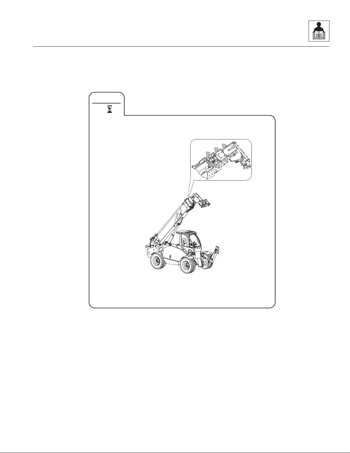
17M
OZ2430
EVERY
8
General Information and Specifications
3508PS, 3509PS, 3512PS, 3513PS, 4008PS, 4009PS, 4012PS, 4013PS, 4017PS, 40.8, 40.9
2-17
General Information and Specifications
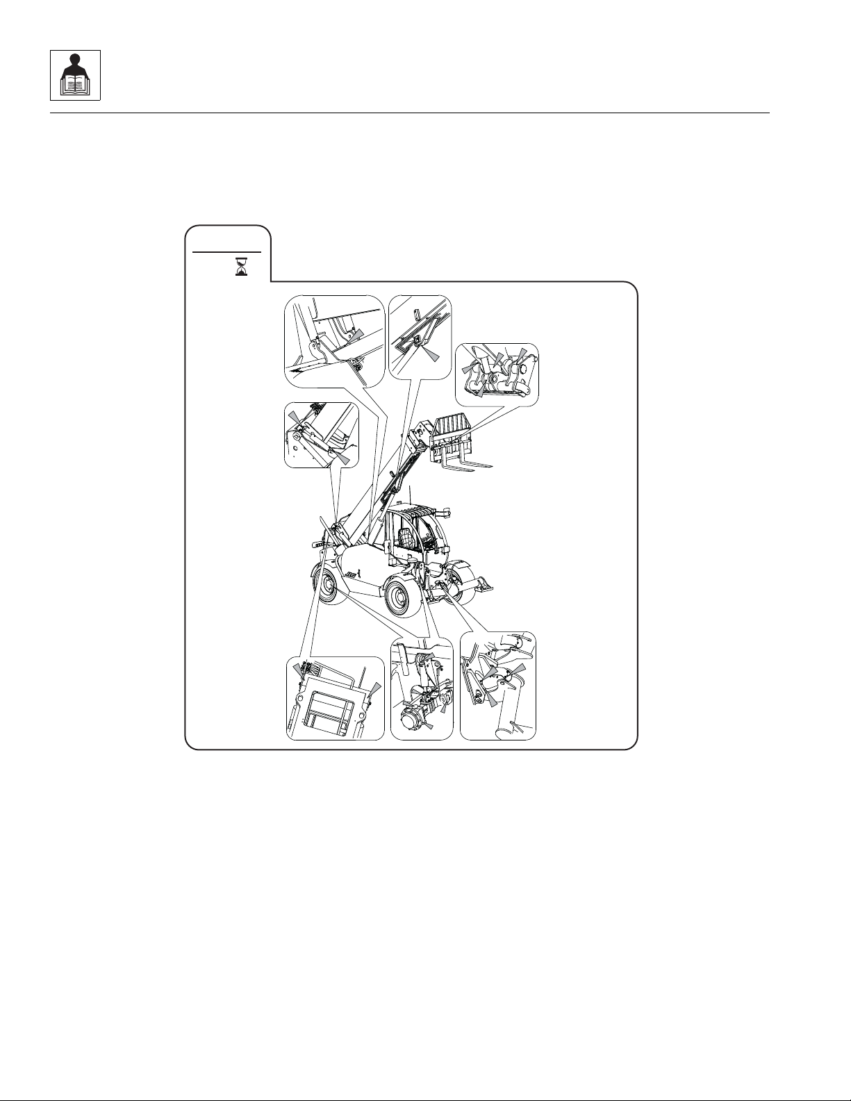
2x
OZ2270
50
EVERY
2.6.2 50 Hour Lubrication Schedule
8, 9, 12 & 13M
2-18
3508PS, 3509PS, 3512PS, 3513PS, 4008PS, 4009PS, 4012PS, 4013PS, 4017PS, 40.8, 40.9
17M
OZ2440
2X
50
EVERY
General Information and Specifications
3508PS, 3509PS, 3512PS, 3513PS, 4008PS, 4009PS, 4012PS, 4013PS, 4017PS, 40.8, 40.9
2-19

General Information and Specifications
This Page Intentionally Left Blank
2-20
3508PS, 3509PS, 3512PS, 3513PS, 4008PS, 4009PS, 4012PS, 4013PS, 4017PS, 40.8, 40.9

Section 3
Boom
Contents
PARAGRAPH TITLE PAGE
3.1 Boom System Component Terminology - Two a nd Three Section Boom . . . . . 3-3
3.2 Boom System - Two and Three Section Boom. . . . . . . . . . . . . . . . . . . . . . . . . . . 3-4
3.2.1 Boom System Description. . . . . . . . . . . . . . . . . . . . . . . . . . . . . . . . . . . . . 3-4
3.3 Boom Assembly Maintenance - Two and Three Section Boom . . . . . . . . . . . . . 3-4
3.3.1 Boom Removal . . . . . . . . . . . . . . . . . . . . . . . . . . . . . . . . . . . . . . . . . . . . . 3-4
3.3.2 Second Section Boom Removal (12 & 13M). . . . . . . . . . . . . . . . . . . . . . . 3-5
3.3.3 Third Section Boom Removal (12 & 13M) Second Section Boom Removal (8 &
9M) . . . . . . . . . . . . . . . . . . . . . . . . . . . . . . . . . . . . . . . . . . . . . . . . . . . . . . 3-5
3.3.4 Third Section Boom Installation (12 & 13M) Second Section Boom Installation (8
& 9M). . . . . . . . . . . . . . . . . . . . . . . . . . . . . . . . . . . . . . . . . . . . . . . . . . . . . 3-6
3.3.5 Second Section Boom Installation (12 & 13M) . . . . . . . . . . . . . . . . . . . . . 3-6
3.3.6 Boom Installation. . . . . . . . . . . . . . . . . . . . . . . . . . . . . . . . . . . . . . . . . . . . 3-7
3.4 Boom System Component Terminology - Four Section Boom. . . . . . . . . . . . . . 3-8
3.5 Boom System - Four Section Boom . . . . . . . . . . . . . . . . . . . . . . . . . . . . . . . . . . . 3-9
3.5.1 Boom System Operation. . . . . . . . . . . . . . . . . . . . . . . . . . . . . . . . . . . . . . 3-9
3.6 Boom Assembly Maintenance - Four Section Boom. . . . . . . . . . . . . . . . . . . . . . 3-9
3.6.1 Boom Removal . . . . . . . . . . . . . . . . . . . . . . . . . . . . . . . . . . . . . . . . . . . . . 3-9
3.6.2 Second, Third and Fourth Boom Section Removal. . . . . . . . . . . . . . . . . . 3-10
3.6.3 Third and Fourth Boom Section Removal. . . . . . . . . . . . . . . . . . . . . . . . . 3-11
3.6.4 Fourth Boom Section Removal. . . . . . . . . . . . . . . . . . . . . . . . . . . . . . . . . 3-12
3.6.5 Hose Carrier Removal. . . . . . . . . . . . . . . . . . . . . . . . . . . . . . . . . . . . . . . . 3-12
3.6.6 Hose Carrier Installation . . . . . . . . . . . . . . . . . . . . . . . . . . . . . . . . . . . . . . 3-12
3.6.7 Fourth Boom Section Installation . . . . . . . . . . . . . . . . . . . . . . . . . . . . . . . 3-13
3.6.8 Third and Fourth Boom Section Installation . . . . . . . . . . . . . . . . . . . . . . . 3-13
3.6.9 Second, Third and Fourth Boom Section Installation . . . . . . . . . . . . . . . . 3-14
3.6.10 Boom Installation. . . . . . . . . . . . . . . . . . . . . . . . . . . . . . . . . . . . . . . . . . . . 3-17
3.7 Boom Extend and Retract Chains Four Section Boom. . . . . . . . . . . . . . . . . . . . 3-18
3.7.1 Boom Chain Inspection. . . . . . . . . . . . . . . . . . . . . . . . . . . . . . . . . . . . . . . 3-18
3.7.2 Inspection Guidelines . . . . . . . . . . . . . . . . . . . . . . . . . . . . . . . . . . . . . . . . 3-18
3.7.3 Expose Chains for Inspection. . . . . . . . . . . . . . . . . . . . . . . . . . . . . . . . . . 3-20
3.7.4 Chain Lubrication . . . . . . . . . . . . . . . . . . . . . . . . . . . . . . . . . . . . . . . . . . . 3-21
3.8 Boom Section Separation Adjustment - Four Section Boom . . . . . . . . . . . . . . . 3-21
3.9 Hose Carrier Assembly - Four Section Boom . . . . . . . . . . . . . . . . . . . . . . . . . . . 3-22
3.9.1 Hose Carrier Assembly Removal . . . . . . . . . . . . . . . . . . . . . . . . . . . . . . . 3-22
3.9.2 Hose Carrier Assembly Replacement. . . . . . . . . . . . . . . . . . . . . . . . . . . . 3-23
3508PS, 3509PS, 3512PS, 3513PS, 4008PS, 4009PS, 4012PS, 4013PS, 4017PS, 40.8, 40.9
3-1

Boom
3.10 Boom Wear Pads. . . . . . . . . . . . . . . . . . . . . . . . . . . . . . . . . . . . . . . . . . . . . . . . . . . 3-25
3.10.1 Wear Pad Inspection. . . . . . . . . . . . . . . . . . . . . . . . . . . . . . . . . . . . . . . . . 3-25
3.10.2 Wear Pad Installation and Lubrication . . . . . . . . . . . . . . . . . . . . . . . . . . . 3-25
3.11 Quick Switch Assembly . . . . . . . . . . . . . . . . . . . . . . . . . . . . . . . . . . . . . . . . . . . . . 3-26
3.11.1 Connecting with a Mechanical Quick Switch Device. . . . . . . . . . . . . . . . . 3-26
3.11.2 Connecting with a Hydraulic Quick Switch Device . . . . . . . . . . . . . . . . . . 3-26
3.11.3 Connecting with a Quick Switch to a Hydraulic Operated Attachment . . . 3-26
3.11.4 Quick Switch Removal . . . . . . . . . . . . . . . . . . . . . . . . . . . . . . . . . . . . . . . 3-27
3.11.5 Quick Switch Installation . . . . . . . . . . . . . . . . . . . . . . . . . . . . . . . . . . . . . . 3-27
3.12 Forks. . . . . . . . . . . . . . . . . . . . . . . . . . . . . . . . . . . . . . . . . . . . . . . . . . . . . . . . . . . . . 3-27
3.13 Troubleshooting . . . . . . . . . . . . . . . . . . . . . . . . . . . . . . . . . . . . . . . . . . . . . . . . . . . 3-28
3-2
3508PS, 3509PS, 3512PS, 3513PS, 4008PS, 4009PS, 4012PS, 4013PS, 4017PS, 40.8, 40.9

3.1 BOOM SYSTEM COMPONENT
MZ1480
SECOND
BOOM
SECTION
FIRST
BOOM
SECTION PIVOT PIN
EXTEND/RETRACT
CYLINDER
TILT CYLINDER
ACCESS
PANEL
QUICK SWITCH
ACCESS
PANEL
QUICK SWITCH
SECOND
BOOM
SECTION
EXTEND/RETRACT
CYLINDER
PIVOT PIN
FIRST
BOOM
SECTION
THIRD
BOOM
SECTION
THREE SECTION BOOM
TWO SECTION BOOM
TILT CYLINDER
TERMINOLOGY - TWO AND THREE
SECTION BOOM
To understand the safety, operation and maintenance
information presented in this section, it is necessary that
the operator/mechanic be familiar with the names and
locations of the major assemblies of the boom system.
The following illustration identifies the components that
are referred to throughout this section.
Boom
3508PS, 3509PS, 3512PS, 3513PS, 4008PS, 4009PS, 4012PS, 4013PS, 4017PS, 40.8, 40.9
3-3

Boom
3.2 BOOM SYSTEM - TWO AND THREE SECTION BOOM
3.2.1 Boom System Description
The boom operates via an interchange among the
electrical, hydraulic and mechanical systems. Components
involved include the joystick, tilt cylinder, extend/retract
cylinder, lift/lower cylinder, compensation cylinder,
electronic sensors, various pivots, supporting hardware
and other components.
3.3 BOOM ASSEMBLY MAINTENANCE TWO AND THREE SECTION BOOM
Note: Boom replacement must be completed in
sequence, one boom section at a time
these instructions.
Before beginning, conduct a visual inspection of the
machine and work area, and review the task about to be
undertaken. Read, understand and follow these
instructions.
3.3.1 Boom Removal
1. Remove any attachment from the quick switch
assembly. Refer to Section 3.11.1, “Connecting with
a Mechanical Quick Switc h Devi ce .”
Note: If replacing the innermost boom section, remove
the quick switch assembly. Refer to Section 3.11.4,
“Quick Switch Removal.”
2. Park the machine on a hard, level surface. Be sure
there is enough room in front of the machine to allow
the boom sections to be removed.
3. Fully retract the boom then raise the boom to access
the rod end pin of the lift/lower cylinder. Place the
transmission control lever in (N) NEUTRAL, engage
the park brake and shut the engine OFF.
4. Place a Do Not Operate Tag on both the ignition key
switch and steering wheel stating that the machine
should not be operated.
5. Open the engine cover. Allow the system fluids to
cool.
6. Properly disconnect the battery.
7. Relieve any trapped pressure in the tilt hydraulic
system by using the handle or wrench (located in the
toolbox) and move the double nut on the side of the
actuator module on the tilt valve section back and
forth. Repeat on the auxiliary valve section and on
the extend/retract section.
, as described in
8. Label, disconnect and cap hydraulic hoses attached
the hose rack at the left rear corner of the boom.
9. Disconnect the boom angle indicator rod from the
switch at the inside left corner of the main boom
section and frame. Refer to Section 9.14.7, “Boom
Angle Sensor.”
10. Support the front of the boom by placing a sling
behind the boom head. Support the lift/lower cylinder
and remove the lock bolt and then the rod end pin.
Lower the lift/lower cylinder onto the frame rails.
11. Lower the boom to a level position and place a
suitable support under the boom head. Reposition
the slings to each end of the boom.
12. Remove the lock bolt and pin from the compensation
cylinder on each side of the first boom section.
Remove the lock bolt and pivot pin from rear of first
boom section.
13. Lift the complete boom off machine and set on level
ground or supports being careful not to damage the
tubes on the side of the first boom section.
a. If the boom is going to be disassembled after
removal:
1. Set the complete boom on level ground and by
repositioning the slings, turn boom over on to the top
side. Set the complete boom on suitable stands to
begin teardown.
Note: With the complete boom setting upside down, the
other boom section(s), tilt cylinder and hoses are made
more accessible.
2. Remove the access panel from the boom head.
3. Label, disconnect and cap the hoses attached to the
tilt cylinder and the hose rack on the side of the first
boom section.
4. Attach a sling through the rod end of the tilt cylinder.
Remove the clip from the barrel end of the tilt
cylinder pin. Remove the tilt cylinder pin and lift the
tilt cylinder out of the boom head.
5. Remove the hose clamp inside the innermost boom
section.
6. Label, disconnect and cap the hoses attached to the
extend/retract cylinder at the rear of the boom.
3-4
3508PS, 3509PS, 3512PS, 3513PS, 4008PS, 4009PS, 4012PS, 4013PS, 4017PS, 40.8, 40.9

7. Pull the extend/retract, tilt and auxiliary hoses (1) out
MZ1720
1
2
3
MZ1740
4
5
6
MZ1730
7
through the rear of the boom.
8. Remove the clip from the rear extend/retract cylinder
pin (2).
9. On 12 & 13M machines, remove the 2 brackets that
secure the extend/retract cylinder to the second
boom section.
10. Use a sling around the innermost boom section to
take any pressure off of the wear pads to make pad
removal easier.
1 1. Use a sling to pull the remaining boom section(s) out
far enough to gain access to the rod end of the
extend/retract cylinder.
12. Remove the clip from the front extend/retract
cylinder pin. Pull the extend/retract cylinder (3) out
through the rear of the boom.
Boom
1. With the boom sections sitting on suitable supports,
use a sling around the third boom section (4) to take
any pressure off of wear pads to make pad removal
easier.
2. Remove the top, left and right side wear pads,
backing plates and shims. Loosen the bottom wear
pad bolts and remove the shims from the first boom
section to gain the necessary clearance to remove
the first boom section from the second boom section
(5). Tag each pad, backing plate, shim and bolts
from each location.
3. Pull the second and third boom sections out from the
first boom section (6).
3.3.3 Third Section Boom Removal (12 & 13M) Second Section Boom Removal (8 & 9M)
3.3.2 Second S e c tion Bo o m Remova l (12 & 13M)
1. Remove the top left and right side wear pads,
2. Pull out the innermost boom section (7).
3508PS, 3509PS, 3512PS, 3513PS, 4008PS, 4009PS, 4012PS, 4013PS, 4017PS, 40.8, 40.9
3. Remove the remaining wear pads.
backing plates and shims. Loosen the bottom wear
pad bolts and remove the shims from the innermost
boom section to gain the necessary clearance to
remove the last boom section (7). Tag each pad,
backing plate, shim and bolts from each location.
3-5

Boom
MZ1750
8
MZ1730
9
3.3.4 Third Section Boom Installation (12 & 13M) Second Section Boom Installation (8 & 9M)
1. Install the bottom rear wear pads (8) and bolts onto
the innermost boom section. Apply Loctite
and torque to 90 Nm (66 lb-ft). Install the bottom rear
left and right side wear pads, backing plate and bolts
(do not shim or tighten bolts). Install top rear wear
pads, backing plates and bolts (do not shim or
tighten bolts).
2. Grease the inside of the next boom section on areas
where the innermost boom section wear pads will
slide.
3. Using a suitable sling, balance the innermost boom
section and carefully slide 1 m to 1,5 m (3’ to 4’) into
the front of the next boom section. Set the innermost
boom section head onto suitable supports and reset
sling under the boom head. Carefully slide the
innermost boom section into the next section. Leave
15 cm to 20 cm (6” to 8”) of the innermost boom
section out to be able to install wear pads on the
front of the next boom section.
4. With the boom head still supported, install the top
wear pads, washers and bolts in the front of the
®
larger boom section. Apply Loctite
243TM and torque
to 90 Nm (66 lb-ft). Remove the boom head from
supports and install the bottom wear pads, backing
plates, shims and bolts in the front of the larger
®
boom section. Apply Loctite
243TM and torque to 90
Nm (66 lb-ft). Install both left and right side front
wear pads, backing plates, shims and bolts in the
front of the larger boom section. Apply Loctite
and torque to 50 Nm (37 lb-ft).
®
243TM
®
243TM
Note: Shim ALL side wear pads as needed to maintain
a minimum gap in the horizontal direction or a tight fit.
The number of shims can vary at each shim point except
on the bottom wear pads.
Note: Light lubrication of the boom wear surfaces with a
factory authorized grease is recommended to keep the
boom wear surfaces lubricated properly.
5. Tighten all wear pads after ensuring the minimum
gap requirements have been met. Refer to Section
3.10.1, “Wear Pad Inspection.”
3.3.5 Second Section Boom Installation (12 & 13M)
1. Install the bottom rear wear pads (9) and bolts onto
the second boom section. Apply Loctite
torque to 90 Nm (66 lb-ft). Install the bottom rear left
and right side wear pads, backing plate and bolts (do
not shim or tighten bolts). Install top rear wear pads,
backing plates and bolts (do not shim or tighten
bolts).
2. Grease the inside of the first boom section on areas
where the third boom section wear pads will slide.
3. Using a suitable sling, balance the first and second
boom sections and carefully slide 1 m to 1,5 m
(3’ to 4’) into the front of the third boom section.Set
the third boom section head onto suitable supports
and reset sling under the boom head. Carefully slide
the first and second boom sections into the first
section. Leave 15 cm to 20 cm (6” to 8”) of the
second boom section out to be able to install wear
pads on the front of the first boom section.
®
243TM and
3-6
3508PS, 3509PS, 3512PS, 3513PS, 4008PS, 4009PS, 4012PS, 4013PS, 4017PS, 40.8, 40.9

Boom
4. With the boom head still supported, install the top
wear pads, washers and bolts in the front of the first
®
boom section. Apply Loctite
243TM and torque to
90 Nm (66 lb-ft). Remove the boom head from
supports and install the bottom wear pads, backing
plates, shims and bolts in the front of the first boom
®
section. Apply Loctite
243TM and torque to 90 Nm
(66 lb-ft). Install both left and right side front wear
pads, backing plates, shims and bolts in the front of
®
the first boom section. Apply Loctite
243TM and
torque to 50 Nm (37 lb-ft).
Note: Shim ALL side wear pads as needed to maintain
a minimum gap in the horizontal direction or a tight fit.
The number of shims can vary at each shim point except
on the bottom wear pads.
Note: Light lubrication of the boom wear surfaces with a
factory authorized grease is recommended to keep the
boom wear surfaces lubricated properly.
5. Tighten all wear pads after ensuring the minimum
gap requirements have been met. Refer to Section
3.10.1, “Wear Pad Inspection.”
3.3.6 Boom Installation
1. Insert the extend/retract cylinder through the rear of
the boom. Align the extend/retract rod end with the
cylinder pin mounting hole on the last boom section.
Install the extend/retract cylinder pin and retaining
clip.
Note: On 12 & 13M machines, install the two brackets
the secure the extend/retract cylinder to the second
boom section.
2. Align the extend/retract barrel end with the cylinder
pin mounting hole on the first boom section. Install
the extend/retract cylinder pin and retaining clip.
Note: Grease extend/retract cylinder barrel end bore
and pin before installing.
8. Rebalance the boom assembly with slings, lift and
carefully guide the boom into place. Align the frame
pivot bore with the boom pivot bore. Install the boom
®
pivot pin. Ap ply L oct ite
243TM and torque to 300 Nm
(221 lb-ft).
9. With the sling still in place, install both compensation
cylinders, pins and lock bolts. Apply Loctite
®
243TM
and torque to 120 Nm (88 lb-ft).
10. With the sling still in place, raise the boom enough to
install the lift/lower pin and lock bolt. Apply Loctite
TM
and torque to 300 Nm (221 lb-ft).
243
®
Note: Raising the boom up or down with the sling
maybe necessary so the boom, compensation and lift/
lower cylinder bores can be aligned for easier pin
installation.
Note: Grease the boom pivot bore, compensation
cylinder rod ends, lift/lower rod end and pins before
installing.
11. Uncap and connect the previously labeled hydraulic
hoses to the hose rack on the side of the first boom
section.
12. Connect the boom angle indicator rod from switch at
the inside left rear corner of the main boom section
and frame. Refer to Section 9.14.7, “Boom Angle
Sensor,” for adjustment information.
13. Properly connect the battery.
14. Start the engine and operate all boom functions
several times. Check for leaks, and check the
hydraulic oil level in the reservoir; add oil if required.
15. Install the access panel on the boom head.
16. Remove the Do Not Operate Tags from both the
ignition key switch and the steering wheel.
17. Close and secure the engine cover.
3. Attach a sling through the rod end of the tilt cylinder
and position the cylinder to its original mounting
location. Install the tilt cylinder pins and retaining
clips.
4. Insert the extend/retract, tilt and auxiliary hoses
through the boom.
5. Uncap and connect the previously labeled hydraulic
hoses to the appropriate locations on each cylinder.
6. Install the hose clamps inside the innermost boom
section.
7. Using suitable slings, turn the boom over to its
original orientation.
3508PS, 3509PS, 3512PS, 3513PS, 4008PS, 4009PS, 4012PS, 4013PS, 4017PS, 40.8, 40.9
3-7

Boom
MZ0800
MZ0810
MZ0830
EXTEND/RETRACT CYLINDER
FIRST BOOM
SECTION
AUXILIARY
QUICK
CONNECTS
TILT CYLINDER
SECOND BOOM
SECTION
THIRD BOOM
SECTION
FOURTH BOOM
SECTION
HOSE CARRIER
EXTEND CHAINS
(TWO PAIR)
BOTTOM VIEW
QUICK SWITCH ASSEMBLY
REAR VIEW
RETRACT CHAINS (THREE)
3.4 BOOM SYSTEM COMPONENT TERMINOLOGY - FOUR SECTION BOOM
To understand the safety, operation and maintenance
information presented in this section, it is necessary that
the operator/mechanic be familiar with the name and
location of the major assemblies of the boom system. The
following illustration identifies the components that are
referred to throughout this section.
3-8
3508PS, 3509PS, 3512PS, 3513PS, 4008PS, 4009PS, 4012PS, 4013PS, 4017PS, 40.8, 40.9

Boom
3.5 BOOM SYSTEM - FOUR SECTION BOOM
3.5.1 Boom System Operation
The four section boom consists of the first, second, third
and fourth assemblies with double third and fourth
section extend chains, a double third section retract
chains and a single fourth section retract chain.
As the extend/retract cylinder, which is anchored at the
front of the second boom section, and the rear of the first
boom section begins to extend, it forces the second boom
section out of the first boom section.
The first, second, third and fourth boom sections are
connected by extend and retract chains. These chains
are routed around sheaves on the second and third boom
sections. As the second and third boom sections are
forced out, the extend chain pulls the fourth boom section
out of the third boom section.
As hydraulic pressure is applied to the retract port on the
extend/retract cylinder, the second boom section is pulled
back into the first boom section, and the retract chain
pulls the third and fourth boom sections back into the
second boom section.
This mechanical linkage formed by the chains and
supporting hardware, extends and retracts the third and
fourth boom sections at the same rate.
The first boom section does not extend or retract, but lifts
and lowers via action of the lift cylinder.
3.6 BOOM ASSEMBLY MAINTENANCE FOUR SECTION BOOM
These instructions must be completed in sequence. The
second, third and fourth boom sections are removed from
the first boom section.The third and fourth boom sections
are removed from the second boom section.The fourth
boom section is removed from the third boom section.
Before beginning, conduct a visual inspection of the
machine and work area, and review the task about to be
undertaken. Read, understa nd and follow thes e
instructions.
3.6.1 Boom Removal
1. Remove any attachment from the quick switch
assembly. Refer to Section 3.11.1, “Connecting with
a Mechanical Quick Switch Device.”
Note: If replacing the innermost boom section, remove
the quick switch assembly. Refer to Section 3.11.4,
“Quick Switch Removal.”
2. Park the machine on a firm, level surface. Be sure
there is enough room in front of the machine to allow
the boom sections to be removed. Fully retract the
boom then raise the boom to access the rod end pin
of lift cylinder. Place the transmission control lever in
(N) NEUTRAL, engage the park brake and shut the
engine OFF.
3. Place a Do Not Operate Tag on both the ignition key
switch and the steering wheel, stating that the
machine should not be operated.
4. Open the engine cover. Allow the system fluids to
cool.
5. Properly disconnect the battery.
6. Label, disconnect and cap both hoses from the
Extend/Ret r ac t cyl ind er, tilt ho s es an d bot h Au xi li ar y
hoses from tubes at left rear corner of first boom
section. Cap all fittings to prevent dirt and debris
from entering the hydraulic system.
7. Remove the Extend/Retract cylinder support at the
top front of the first boom section.
8. Support the Extend/Retract cylinder and remove the
clip and pin from rod end of extend/retract cylinder.
Remove the clip and pin from barrel end of extend/
retract cylinder and remove the extend/retract
cylinder.
9. Disconnect the boom angle indicator rod from switch
at the inside left rear corner of the main boom
section and frame.
10. Support the front of the boom by placing a sling
behind the boom head. Support the Lift/Lower
cylinder and remove the lock bolt and then the rod
end pin. Lower the Lift/Lower cylinder onto the frame
rails.
11. Remove the lock bolt and pin from Compensation
cylinder on each side of first boom section. Remove
the lock bolt and pivot pin from rear of first boom
section.
12. Lower the boom to a level position and place a
suitable support under the boom head. Reposition
the slings to each end of the boom.
3508PS, 3509PS, 3512PS, 3513PS, 4008PS, 4009PS, 4012PS, 4013PS, 4017PS, 40.8, 40.9
3-9
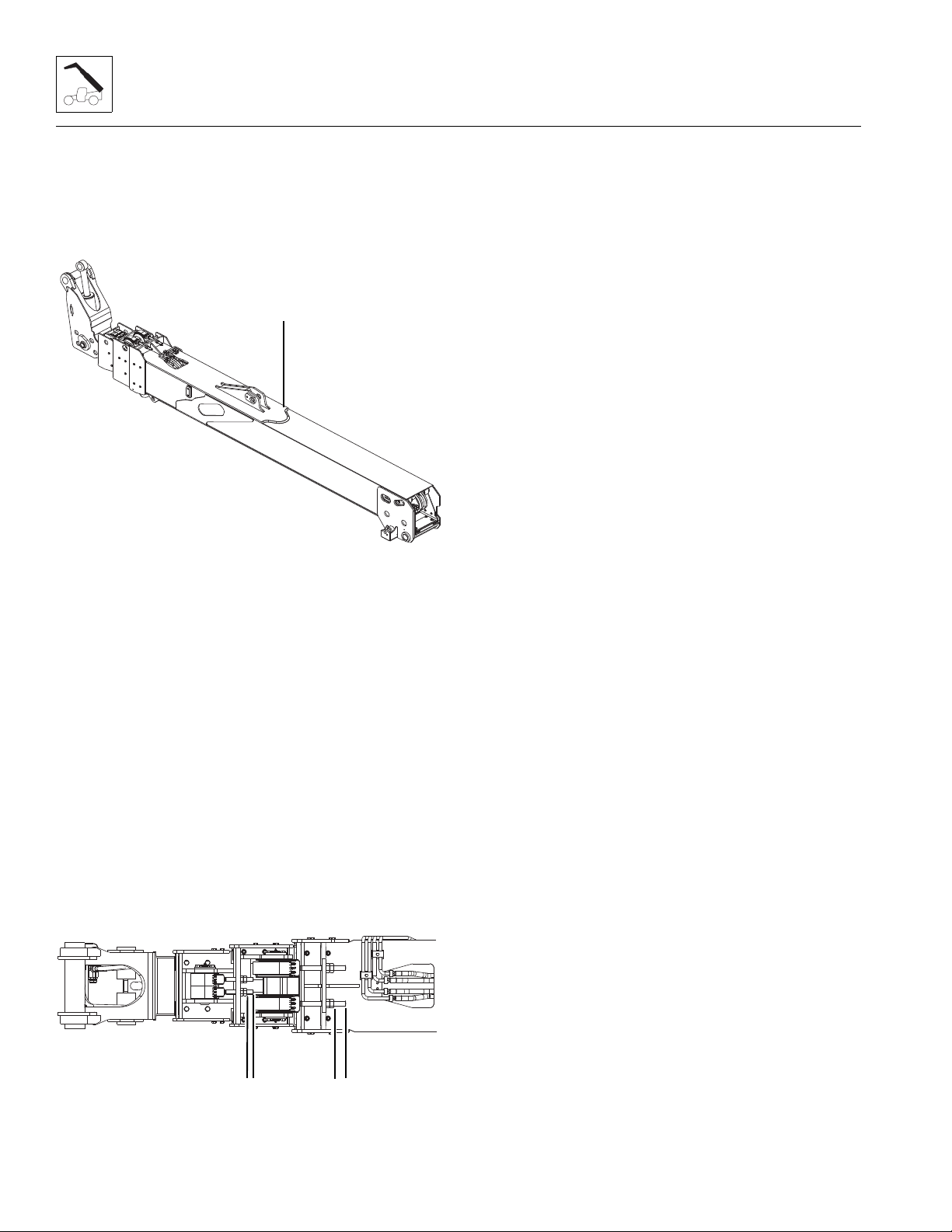
Boom
MZ0740
1
MZ0790
2
2
13. Lift the complete boom off machine and set on level
ground or supports being careful not to damage the
tubes on the left side of boom.
3.6.2 Second, Third and Fourth Boom
Section Removal
1. Set the complete boom on level ground and by
repositioning the slings turn boom over on to the top
side. Set the complete boom (1) on suitable stands
to begin tear down.
Note: With the complete boom setting upside down, the
removal and replacing of each boom section, tilt cylinder,
hoses, extend and retract chains and hose carrier are
made much easier.
2. At the boom head attach a sling through rod end of
tilt cylinder. Label, disconnect and cap both hoses
from Tilt cylinder. Plug the cap all fittings to prevent
dirt and debris from entering the hydraulic system.
Remove the clip from barrel end of tilt cylinder pin.
Remove the tilt cylinder pin and lift the Tilt cylinder
out of the boomhead.
3. Use a suitable sling around the third section boom to
take any pressure off of wear pads to make pad
removal easier.
Note: Before removing the extend chains, measure the
distance (2) between the face of the jam nut to the end of
the chain clevis on all four extend chains. This
measurement will be used when reassembling the
boom.
4. At the bottom front of the first boom section, remove
the jam nuts and nuts and washers from the two
extend chain clevises. Remove clips and pins from
the two clevises and remove clevis from each chain.
5. At the bottom front of the second boom section
remove the jam nuts and nuts and washers from the
two extend chain clevises. Remove clips and pins
from the two clevises and remove clevis from each
chain.
6. At the rear of the boom, label, disconnect and cap
both Tilt hoses and both Auxiliary hoses from the
bulkhead on the hose carrier. Cap all fittings to
prevent dirt and debris from entering the hydraulic
system.
7. Remove the clip and pin from both retract chain
clevises that are attached to the rear of the third
section boom. The pins can be removed through the
access holes at the bottom left and right sides of the
first section boom. Do not remove the clevises.
8. Remove the clip and pin from the retract chain clevis
that is attached to the rear of the fourth boom
section. Do not remove the clevis.
9. Pull the second section boom out 152 mm to
203 mm (6 in to 8 in) and remove all the wear pads
from the front inside of the first section boom. Label
all parts for installation.
10. Pull the third boom section out 152 mm to 203 mm
(6 in to 8 in). Remove the top left and right side wear
pads from the second boom section. Loosen the
bottom rear wear pad bolts and remove the shims
from the second boom section to gain the necessary
clearance to be able to remove the second boom
section from the first boom section. Label all parts
for installation.
3-10
3508PS, 3509PS, 3512PS, 3513PS, 4008PS, 4009PS, 4012PS, 4013PS, 4017PS, 40.8, 40.9

11. Using a sling around the front of the second boom
MZ0760
3
section, lift and slide the three boom sections 75% of
the way out of the first boom section. Set the boom
head down on a suitable support, then center the
sling to be able to balance the three boom sections
being removed. Carefully pull the three boom
sections the remainder of the way out of the first
boom section and set the three boom sections down
on suitable supports.
12. Remove the clip and pin holdi ng each ret ract cha in
from the inside of the first boom section. Clean and
inspect chains. Replace if damaged.
13. Label, disconnect and cap the Tilt and Auxiliary
hydraulic hoses from tubes at bottom front of first
boom section. Plug all fittings to prevent dirt and
debris from entering hydraulic system. Clean and
inspect the hoses. Replace if damaged.
14. Inspect the boom and welds. Consult your local
authorized service distributor if structural damage is
detected.
15. Inspect hoses, hardware, wear pads, mounting
points, chains and other components visible with the
first boom section. Replace any item if damaged.
(Refer to Section 3.7.1, “Boom Chain Inspection,”
and Section 3.10.1, “Wear Pad Inspection.”)
Note: It is recommended that if any chain or hose is
damaged that ALL chains or hoses are replaced.
3.6.3 Third and Fourth Boom Section
Removal
1. With the three boom sections setting on suitable
supports remove bolts, keeper and pin from both
sheaves on the bottom front of the second boom
section. Remove sheaves. Remove all wear pads on
the front inside of the second boom section. Label all
parts for installati on.
2. Remove the bolts, keeper and pin from center
sheave on the bottom rear of the third boom section.
Remove the sheave.
3. Remove the top left and right side rear wear pads on
the third boom section. Loosen the bottom rear wear
pad bolts and remove the shims from the third boom
section to gain the necessary clearance to remove
the third boom section from the second boom
section. Label all parts for installation.
Boom
4. Place a sling around the front of the third boom
section. Lift and slide the two boom sections 75% of
the way out of the second boom section. Set the
boom head down on a suitable support, then center
the sling to be able to balance the two boom
sections being removed. Carefully pull the two boom
sections (3) the remainder of the way out of the
second boom section and set the two boom sections
down on suitable supports.
5. Remove the lock bolts, keeper and pin from both
sheaves at bottom rear of the second section boom.
Remove the sheaves.
6. Remove the clip and pin holding retract chain from
bottom front of second boom section. Clean and
inspect chain. Replace if damaged.
7. Inspect the boom and welds. Consult your local
aut horized se rvice distr ibutor if structural damage is
detected.
8. Inspect hoses, hardware, wear pads, mounting
points, chains and other components visible with the
first boom section. Replace any item if damaged.
(Refer to Section 3.7.1, “Boom Chain Inspection,”
and Section 3.10.1, “Wear Pad Inspection.”)
Note: It is recommended that if any chain or hose is
damaged that ALL chains or hoses are replaced.
3508PS, 3509PS, 3512PS, 3513PS, 4008PS, 4009PS, 4012PS, 4013PS, 4017PS, 40.8, 40.9
3-11

Boom
MZ0770
4
MZ2720
5
3.6.4 Fourth Boom Section Removal
1. With the two boom sections setting on suitable
supports remove the bolts, keeper and pin from
sheave on the front of the third boom section.
Remove the sheaves. Remove all wear pads, from
the front inside of the third boom section. Label all
parts for installation.
2. Remove the top left and right side rear wear pads on
the fourth boom section. Loosen the bottom rear
wear pad bolts and remove the shims from the fourth
boom section to gain the necessary clearance to be
able to remove the fourth boom section from the
third boom section. Label all parts for installation.
3. Loosen and remove the two bolts holding the rear of
the hose carrier to the top of the third boom section.
Lift and push rear of hose carrier into the fourth
boom section.
Note: It is recommended that if any chain or hose is
damaged that ALL chains or hoses are replaced.
3.6.5 Hose Carrier Removal
1. Label, disconnect and cap both auxiliary hydraulic
hoses in the boom head. Cap all fittings to prevent
dirt and debris from entering hydraulic system.
2. With fourth boom section setting on suitable
supports loosen and remove the six bolts (three per
side) on the fourth boom section.
3. Pull the hose carrier (5) halfway out of fourth boom
section by hand and set on a suitable support. Place
a sling around the center of the hose carrier to be
able to balance the hose carrier while being
removed. Carefully slide the hose carrier the
remainder of the way out of the fourth boom section
and set down on suitable supports.
4. Place a sling around the front of the fourth boom
section (4). Lift and slide the fourth boom section 3/4
of the way out of the third boom section. Set the
boom head down on a suitable support, then center
the sling to be able to balance the fourth boom
section being removed. Carefully pull the fourth
boom section the remainder of the way out of the
third boom section and set the fourth boom section
down on suitable supports.
5. Remove the clip and pin holding both extend chains
from bottom of third and fourth boom sections. Clean
and inspect chains. Replace if damaged.
6. Inspect the boom and welds. Consult your local
authorized service distributor if structural damage is
detected.
7. Inspect hoses, hardware, wear pads, mounting
points, chains and other components visible with the
first boom section. Replace any item if damaged.
(Refer to Section 3.7.1, “Boom Chain Inspection,”
and Section 3.10.1, “Wear Pad Inspection.”)
3-12
3508PS, 3509PS, 3512PS, 3513PS, 4008PS, 4009PS, 4012PS, 4013PS, 4017PS, 40.8, 40.9
3.6.6 Hose Carrier Installation
1. Install the hose carrier into the fourth boom section.
Using a suitable sling, place the sling under the
center of the hose carrier and guide the front of hose
carrier into the rear of the fourth boom section. Set
the rear of the hose carrier on a suitable support.
Remove the sling and slide the remainder of the
hose carrier into the fourth boom section by hand.
®
2. Apply Loctite
the bolts through the three holes on each side of the
fourth boom section. Install the front two bolts first.
Install the middle two next. Then the rear two bolts
last. Torque to all six bolts to 90 Nm (66 lb-ft).
243TM to the hose carrier bolts. Install
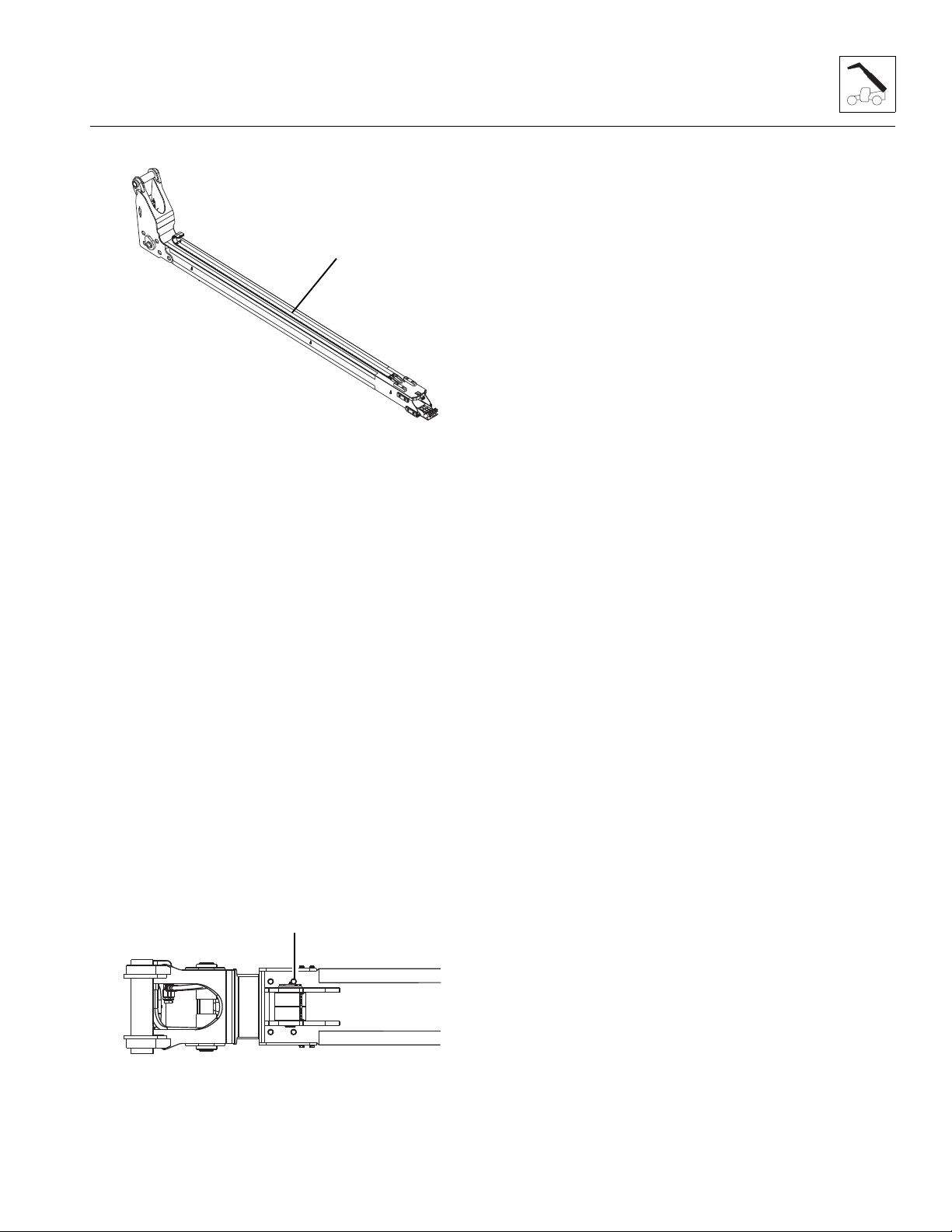
3.6.7 Fourth Boom Section Installation
MZ0770
6
MZ0980
7
1. Apply Loctite® 243TM to the wear pad mounting bolts.
Install the bottom, left right and top wear pads. Do
not shim or tighten the side and top wear pad bolts
at this time. Install both extend chains (6) on bottom
rear of fourth boom section. Lay extend chains the
length of fourth boom section.
2. Grease the inside third boom section on area’s
where the fourth boom section wear pads will slide.
3. Using a suitable sling, balance the fourth boom
section and carefully slide 914 mm to 1219 mm
(3 ft to 4 ft) into the front of the third boom section.
Set the fourth boom section head onto suitable
support and reset sling under the boom head of the
fourth boom section. Carefully slide the fourth boom
section into the third boom section. Leave
1829 mm to 2438 mm (6 ft to 8 ft) of the fourth boom
section out to be able to install wear pads in front of
the third boom section.
4. With the sling still under boom head install the top
wear pads. Lower the fourth boom section and install
the bottom, left and right side wear pads. Do not
shim or tighten bolts at this time.
Note: Grease wear pads, inside sheaves, bores and
pins during assembly.
Boom
®
5. Apply Loctite
243TM to the sheave mounting bo lt s,
Install the sheave (7), pin, lock pla te an d b ol ts at t he
bottom front of the third boom section. Torque bolts to
90 Nm (66 lb-ft). Grease the sheave using the
grease fitting in the pin. Spin the sheave by hand to
ensure the sheave spins freely on the pin and to
distribute grease evenly . Pull both extend c hains from
the fourth boom section around the front and over the
sheave. Install both ch ai n clev is es, pi ns an d clip s.
6. Retract the fourth boom section the remainder of the
way into the third boom section and install the wear
pads at the rear of third and fourth boom sections.
®
7. Apply Loctite
243TM to the wear pad mounting bolts
and install the bottom left and right side wear pads,
backing plates, shims and bolts. Shim the top wear
pads on the rear of the fourth boom section. Shim
the top left and right wear pads on the rear of the
fourth boom section. Torque bolts to 90 Nm (66 lb-ft).
Torque grease fitting bolts to 45 Nm (33 lb-ft).
3.6.8 Third and Fourth Boom Section Installation
1. At the rear of the third boom section apply Loctite®
2. Grease the inside second boom section on areas
3. Install retract chain, pin and clip to bottom front
Note: Keep the retract chain centered on bottom of the
third boom sec tion w hile inst alli ng the third boo m sect ion
into the second boom section.
TM
to the wear pad mounting bolts and install the
243
bottom rear wear pads, washers and bolts. T orque to
90 Nm (66 lb-ft). Install the bottom rear left and right
side wear pads, backing plate and bolts (do not shim
or tighten bolts). Install the top rear wear pads,
backing plates and bolts (front bolts are drilled and
tapped for grease fittings. do not shim or tighten
bolts). Install both extend chains on the bottom rear
of the third boom section. Lay extend chains the
length of third boom section.
where the third boom section wear pads will slide.
inside of the second boom section.
3508PS, 3509PS, 3512PS, 3513PS, 4008PS, 4009PS, 4012PS, 4013PS, 4017PS, 40.8, 40.9
3-13
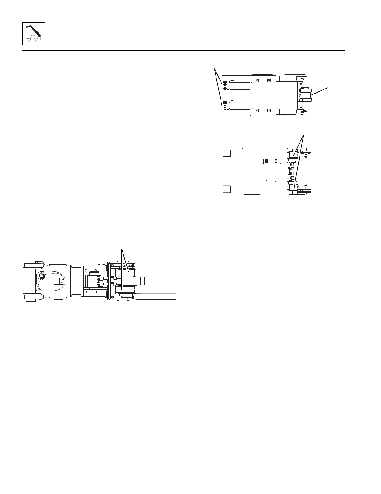
Boom
MZ1000
8
MZ1010
9
1
MZ1140
2
4. Using a suitable sling, balance the third and fourth
boom sections and carefully slide 914 mm-1219 mm
(3 ft - 4 ft) into the front of the second boom section.
Set the third and fourth boom sections onto a
suitable support and reset the sling under the boom
head of the fourth boom section. Carefully slide the
third and fourth boom sections into the second boom
section. Leave 152 mm-203 mm (6 in - 8 in) of the
third boom section out to be able to install the wear
pads in the front of the second boom section.
5. With the sling still under boom head, Apply Loctite
Note: Grease wear pads, inside sheaves, bores and
pins during assembly.
TM
to the wear pad mounting bolts and install the
243
top wear pads, washers and bolts in the front of the
second boom section. Torque to 90 Nm (66 lb-ft).
Lower the third and fourth boom section and apply
®
Loctite
243TM to the wear pad mounting bolts and
install bottom wear pads, backing plates, shims, and
the allenhead cap bolts in the front of the second
boom section. Torque to 90 Nm (66 lb-ft). Install both
left side and right side front wear pads, backing
plates, shims and bolts in the front of the second
boom section. Torque to 90 Nm (66 lb-ft).
®
8. Install the retract chain sheave (1), pin, keeper and
bolts to bottom rear of third boom section. Apply
®
Loctite
243TM and torque to 90 Nm (66 lb-ft). Grease
the sheaves using the grease fitting in the pin. Spin
the sheaves by hand to ensure the sheaves spin
freely on the pin and to distribute grease evenly.
9. Install both retract chain sheaves (2), pin, keeper
and bolts to bottom rear of second boom section.
®
Apply Loctite
243TM and torque to 90 Nm (66 lb-ft).
Grease the sheaves using the grease fitting in the
pin. Spin the sheaves by hand to ensure the
sheaves spin freely on the pin and to distribute
grease evenly.
6. Install both sheaves (8), pins, lock plates and bolts at
the bottom front of the second boom section. Apply
®
Loctite
243TM and torque bolts to 90 Nm (6 6 lb -ft ).
Grease the sheaves using the grease fitting in the
pin. Spin the sheaves by hand to ensure the
sheaves spin freely on the pin and to distribute
grease evenly. Pull both exten d ch ai ns f rom th e t hir d
boom section around the front and over the sheaves.
Install both chai n clev is es, pi ns a nd clip s (9).
®
7. Apply Loctite
243TM to the wear pad mounting bolts
and install the bottom left and right side wear pads,
backing plates, shims and bolts.Shim the top wear
pads on the rear of the third boom section. Shim the
top left and right wear pads on the rear of the third
boom section.Torque bolts to 90 Nm (66 lb-ft).
Torque grease fitting bolts to 45 Nm (33 lb-ft).
3-14
3508PS, 3509PS, 3512PS, 3513PS, 4008PS, 4009PS, 4012PS, 4013PS, 4017PS, 40.8, 40.9
3.6.9 Second, Third and Fourth Boom Section Installation
Note: Light lubrication of the boom wear surfaces with a
factory authorized grease is recommended to keep the
boom wear surfaces lubricated properly. Light lubrication
of the boom wear surfaces is also recommended when
the machine is stored, to help prevent rusting.
®
1. Apply Loctite
At the rear of the second boom section, install the
bottom rear wear pads, washers and bolts. T orque to
90 Nm (66 lb-ft). Install the bottom rear left and right
side wear pads, backing plate and bolts (do not shim
or tighten bolts). Install top rear wear pads, backing
plates and bolts (front bolts are drilled and tapped for
grease fittings. do not shim or tighten bolts).
243TM to the wear pad mounting bolts.
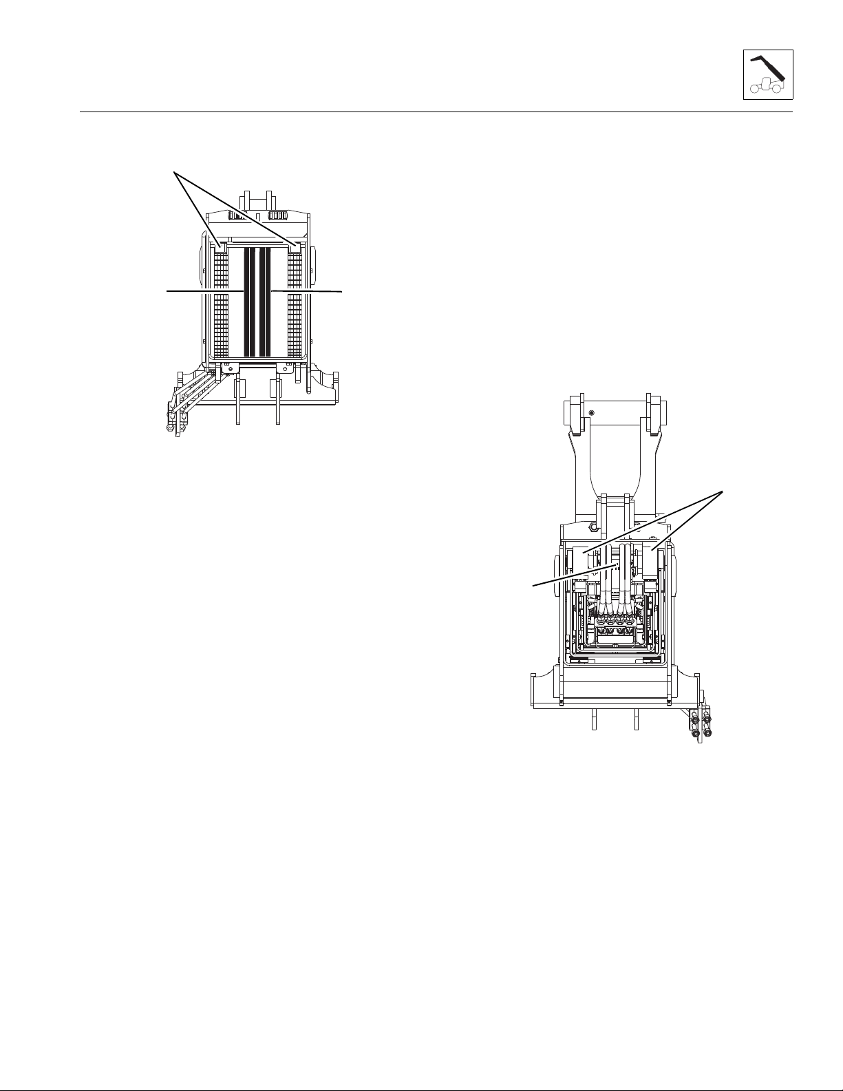
Boom
MZ1190
3
4
5
MZ1200
7
6
2. Grease the inside first boom section on area’s where
the second boom section wear pads will slide.
3. Install the retract chains (3), pins and clips to bottom
front inside of the first boom section.
4. Install both tilt hoses (4) and both auxiliary hoses (5)
to the tubes mounted at the bottom front of the first
boom section. Make sure both sets of hoses are run
through the opening at the bottom front of the first
boom section and run down the inside center of the
boom section
the front of the second boom section. Torque to
90 Nm (66 lb-ft).
Note: Shim ALL side wear pads as needed to maintain
a minimum gap (1.6 mm - 1/16 in) the horizontal
direction or a snug fit. The number of shims can vary at
each shim point.
7. Install the bottom left and right side wear pads,
backing plates, shims and bolts at the rear of the
second boom section.Shim the top wear pads on the
rear of the second boom section. Shim the top left
and right wear pads on the rear of the second boom
®
section. Apply Loctite
243TM and torque bolts to 90
Nm (66 lb-ft).
8. Retract the second, third and fourth boom sections
the remainder of the way into the first boom section.
Note: Keep the retract chains, tilt and auxiliary hoses
centered in the first boom section while installing the
second boom section into the first boom section.
5. Using a suitable sling, balance the second, third and
fourth boom sections and carefully slide
914 mm - 1219 mm (3 ft - 4 ft) into the front of the
first boom section. Set the second, third and fourth
boom sections onto a suitable support and reset
sling under the boom head of the fourth boom
section. Carefully slide the secon d, third and four th
boom sections into the first boom section. Leave
152 mm - 203 mm (6 in - 8 in) of the second boom
section out to be able to install wear pads in front of
the first boom section.
6. With sling still under boom head, Apply Lo ct it e
®
243TM
to the wear pad mounting bolts. Install the top wear
pads, washers and bolts in the front of the first boom
section. Torque to 90 Nm (66 lb-ft). Lower the
second, third and fourth boom sections and apply
®
Loctite
bottom wear pads, backing plates, shims, and bolts
243TM to the wear pad mounting bolts, Install
in the front of the first boom section. Torque to
90 Nm (66 lb-ft). Install both left side and right side
front wear pads, backing plates, shims and bolts in
9. Attach the retract chain (6), pin and clip to the clevis
at the rear of the fourth boom section.
10. Attach the retract chains (7), pins and clips to the
clevises at the rear of the third boom section.
Note: Installing the clevis pins in the third boom section
can only be done when the first boom section and the
second boom section access holes are aligned.
3508PS, 3509PS, 3512PS, 3513PS, 4008PS, 4009PS, 4012PS, 4013PS, 4017PS, 40.8, 40.9
3-15

Boom
MZ0790
8
9
MZ1210
3
2
1
11. Attach both extend chain clevises (8) through the
holes in the bottom front of the first boom section.
Install the washers, adjustment nut and jam nut to
the clevises.
12. Attach both extend chain clevises (9) through the
holes in the bottom front of the second boom
section. Install the washers, adjustment nut and jam
nut to the clevises.
Note: Grease Tilt cylinder barrel end bore and pin
before installing.
17. Using suitable slings, lift complete boom off supports
and set on level ground. It will be necessary to place
a block under the rear of the boom to keep the tilt
and auxiliary tubes from being damaged
18. Turn the boom over being careful not to damage the
Tilt and Auxiliary tubes mounted on the side and rear
of boom.
19. After boom is turned upright, place a suitable
support under the rear of the boom.
20. Attach a sling around a balance point on the Extend/
Retract cylinder and carefully set on top of the first
boom section.
Note: Grease Extend/Retract cylinder barrel end bore
and rod end bore and pins before installing.
Note: Adjust all four extend chains using the
measurement taken in the beginning of the tear down
procedure. Depending on the extent of the parts being
replaced, the above measurement is to be used as a
starting point ONLY.
13. Pull the rear of the hose carrier over the rear of the
fourth boom section and set onto the rear of the third
boom section. Using the two bolts, washers and
nuts, bolt the rear of the hose carrier to the rear of
®
the third boom section. Apply Loctite
243TM and
torque the two bolts to 90 Nm (66 lb-ft).
14. Remove the caps from the fittings on the hose
carrier bulkhead and the plugs from the tilt and
auxiliary hoses. Install all four hoses and tighten until
wrench-tight. Mark the hose fitting then tighten each
hose firmly 1 to 1 1/2 flats.
15. Remove the caps from the Auxiliary hoses in the
boomhead and install the Auxiliary hoses from the
front of the hose carrier to the Auxiliary bulkhead.
Tighten each hose wrench-tight. Mark the hose
fitting then tighten each hose firmly 1 to 1 1/2 flats.
Bolt the auxiliary hose bulkhead to the side of the
boom head and torque the two bolts to 90 Nm
(66 lb-ft).
16. Using a suitable sling through the rod end of the Tilt
cylinder, lower the Tilt cylinder into boomhead. Align
the Tilt cylinder barrel end bore with the boomhead
bore and install the Tilt cylinder pin and retaining
clip.
21. Align the Extend/Retract cylinder barrel end with
bore at rear of the first boom section. Install the pin
and retaining clip (1).
22. Align the Extend/Retract cylinder rod end with bore
at front of the second boom section. Install the pin
and retaining clip (2).
23. Install Extend/Retract cylinder support (3). Apply
®
Loctite
243TM and torque bolts to 90 Nm (66 lb-ft).
3-16
3508PS, 3509PS, 3512PS, 3513PS, 4008PS, 4009PS, 4012PS, 4013PS, 4017PS, 40.8, 40.9
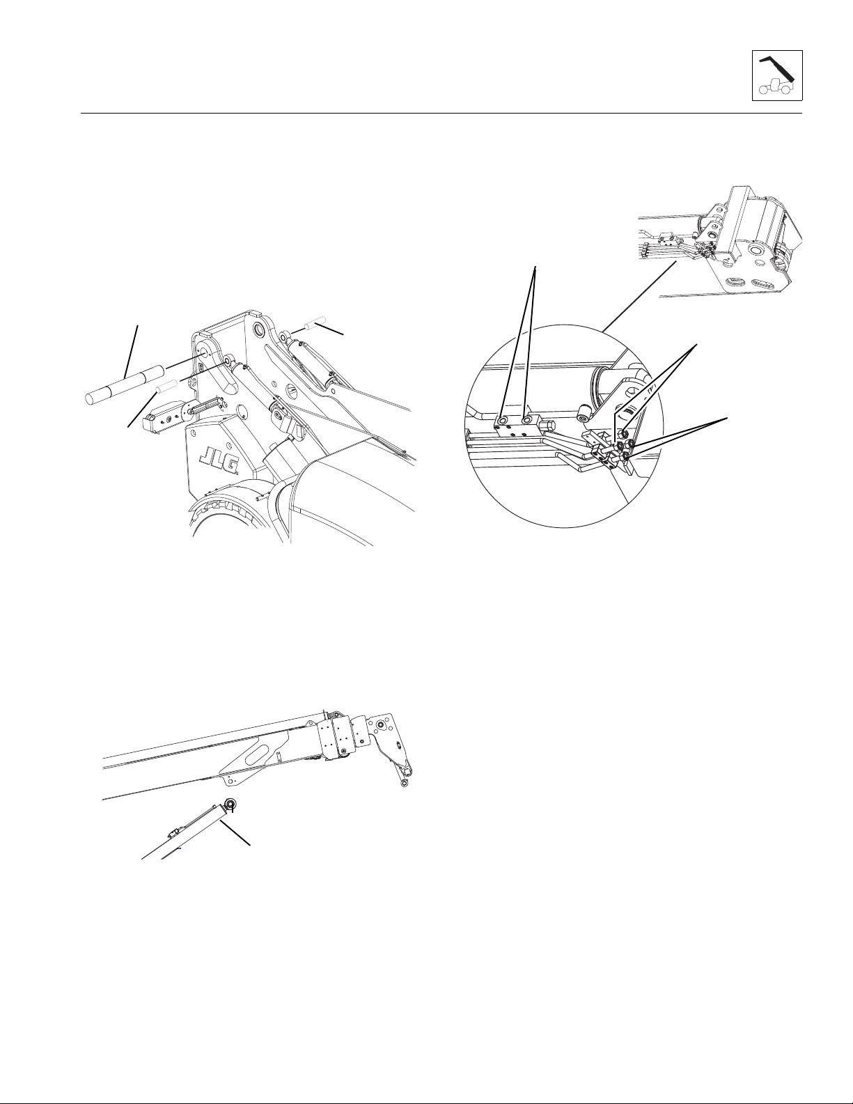
Boom
MZ1230
4
5
5
MZ1240
6
MZ1250
7
9
8
3.6.10 Boom Installation
Note: Light lubrication of the boom wear surfaces with a
factory authorized grease is recommended to keep the
boom wear surfaces lubricated properly. Light lubrication
of the boom wear surfaces is also recommended when
the machine is stored, to help prevent rusting.
1. Park the machine on a hard, level surface. Make
sure park brake is set, key is removed from the
ignition and “Do Not Operate” tag is placed in clear
view in the cab.
Note: Grease the boom pivot bore, compensation
cylinder rod ends, lift/lower cylinder rod end and pins
before installing.
5. Remove the caps from Extend/Retract cylinder
2. Using suitable slings, balance the boom assembly,
lift and carefully guide the boom into place. Align the
frame pivot bore with the boom assembly pivot bore.
®
Install boom pivot pin (4). Apply Loctite
243TM and
torque lock bolt to 90 Nm (66 lb-ft).
3. With the sling still in place, install both
Compensation cylinders, pins and lock bolts (5).
®
Apply Loctite
243TM and torque to 90 Nm (66 lb-ft).
fittings and plugs from Extend/Ret ra ct cy li nde r
hoses. Attach each hose to the Extend/Retract
cylinder fittings (7) and tighten until wrench-tight.
Mark the hose fitting then tighten each hose firmly 1
to 1-1/2 flats.
6. Remove the caps from both Tilt tubes (8) and
Auxiliary tubes (9) and plugs from both Tilt hoses
and both Auxiliary hoses. Attach both sets of hoses
to the Tilt tubes and the Auxiliary tubes and tighten
until wrench-tight. Mark the hose fitting then tighten
each hose firmly 1 to 1-1/2 flats.
7. Connect the boom angle indicator rod from switch at
the inside left rear corner of the main boom section
and frame. Refer to Section 9.14.7, “Boom Angle
Sensor,” for adjustment information.
4. With the sling still in place, install the rod end of the
Lift/Lower cylinder, pin and lock bolt (6). Apply
®
Loctite
243TM and torque to 90 Nm (66 lb-ft).
8. Start the engine and operate all boom functions
several times. Check for leaks, and check the
hydraulic oil level in the reservoir; add oil if required.
9. Clean up all debris, hydraulic oil, etc., in, on, near
and around the machine.
Note: Raising the boom up or down with the sling
maybe necessary so the boom, Compensation and Lift/
Lower cylinder bores can be aligned for easier pin
installation.
3508PS, 3509PS, 3512PS, 3513PS, 4008PS, 4009PS, 4012PS, 4013PS, 4017PS, 40.8, 40.9
3-17

Boom
3.7 BOOM EXTEND AND RETRACT
CHAINS FOUR SECTION BOOM
3.7.1 Boom Chain Inspection
WARNING
Worn pins, stretched or cracked links or corrosive
environments can c ause ch ain failu re. A ch ain failu re
could result in uncontrolled boom move ment, loss of
load or machine instability.
Under normal operating conditions the boom chains will
need to be inspected every 250 hours of operation. The
retract chains need to be exposed and inspected every
1000 hours of operation. Refer to the Service Manual for
the proper procedure. Environmental conditions and
dynamic impulse/shock loads can drastically affect
normal operating conditions and require more frequent
inspection intervals.
Environments in which material handling vehicles
operate can vary widely from outdoor moisture to
temperature to mildly corrosiv e or highl y corr os ive
industrial atmospheres, in addition to abrasive
exposures such as sand and grit. Some effects can be
as follows:
• Moisture - Corrosive rusting reduces chain
strength by pitting and cracking.
• Temperature - Low temperature reduces chain
strength by embrittlement. Going in and out of
cold storage results in moisture from
condensation.
• Chemical Solutions or Vapors - Corrosive attack
on the chain components and/or the mechanical
connections between the chain components.
Cracking can be (and often is) microscopic.
Going from microscopic cracking to complete
failure can be either abrupt or may require an
extended period of time.
• Abrasives - Accelerated wearing and scoring of
the articulating members of the chain (pins and
plates), with a corresponding reduction in chain
strength. Due to the inaccessibility of the bearing
surfaces (pin surfaces and plate apertures),
wear and scoring are not readily noticeable to
the naked eye.
Following are some examples of dynamic shock loading
which can impose abnormal loads above the endurance
limit of a leaf chain.
• High velocity movement of load, followed by
sudden, abrupt stops.
• Carrying loads in suspension over irregular
surfaces such as railroad tracks, potholes, and
rough terrain.
• Attempting to “inch” loads which are beyond the
rated capacity of the vehicle.
The above load cycles and environmental conditions
make it impossible to predict chain life. It is therefore
necessary to conduct frequent inspections until
replacement life can be predicted.
The boom chain’s normal life expectancy can be
expressed as a maximum percent of elongation. This is
generally 3%. As the chain flexes back and forth over the
sheave, the bearing joints (pins and inside link plates)
gradually incur wear due to articulatio
3.7.2 Inspection Guidelines
1. Park the machine on a firm, level surface, raise the
boom to a horizontal (level) position, place the
transmission control lever in (N) NEUTRAL, engage
the park br ake switch.
2. Fully extend the boom until the extend chain is taut.
Shut the engine off.
3. The extend chains will be visible for inspection with
the vehicle in this state.
4. While doing the chain inspection, check all chain
clevis ends for distortion or cracking and sheaves for
bearing wear or grooving from the chain.
5. Inspect the retract chains every 1000 hours of
operation. Refer to the Service Manual for proper
procedure.
6. Inspect the chains for the following conditions:
Edge Wear
Check the chain for wear on the link plate edges
caused by running back and forth over the sheave.
The maximum reduction of material should not
exceed 5%. This can be compared to a normal link
plate height by measuring a portion of chain that
does not run over the sheave.
3-18
a. Extend Chains (fourth to third section)
The extend chains between the fourth and third
boom sections measures 18 mm (.713 in) (1). If the
measurement of the worn chain is less than 17 mm
(.677 in) (2), the chain should be replaced.
3508PS, 3509PS, 3512PS, 3513PS, 4008PS, 4009PS, 4012PS, 4013PS, 4017PS, 40.8, 40.9

b. Extend Chains (third to second section)
MZ1463
1
2
MZ1464
3
4
MZ1465
5
6
7
The extend chains between the third and second
boom sections measures 29,6 mm (1.2 in) (1). If the
measurement of the worn chain is less than
28,6 mm (1.1 in) (2), the chain should be replaced.
Elongation
Boom
It is important to measure the chain in the section
that moves over the sheaves because it receives the
most frequent articulation. Measuring the chain near
its clevis terminals could give an inaccurate reading.
The ends of the chains, near the clevis terminal, will
not have flexed as frequently, if at all, as nearer the
middle of the chains.
a. Extend Chains (fourth to third section)
When the original length (3) of 305 mm (12.00 in)
per foot of extend chain between the fourth and third
boom sections has elongated from wear to a length
(4) of 313 mm (12.36 in), the chain should be
discarded and replaced.
Measure across a span of 16 pins at the center of
the extend chain. Measure from pin center to pin
center. Because the retract chain is inside the boom
you will not be able to measure the chain.
The maximum measurement allowed is
313 mm(12.36 in). If the measurement is more than
313 mm (12.36 in), the chain should be replaced.
b. Extend Chains (third to second section)
When the original length (3) of 317 mm (12.5 in) per
foot of extend chain between the third and second
boom sections has elongated from wear to a length
(4) of 325 mm (12.8 in), the chain should be
discarded and replaced.
Measure across a span of 10 pins at the center of
the extend chain. Measure from pin center to pin
center. Because the retract chain is inside the boom
you will not be able to measure the chain.
The maximum measurement allowed is
325 mm(12.8 in). If the measurement is more than
325 mm (12.8 in), the chain should be replaced.
Turning or Protruding Pins
Highly loaded chain, operating with inadequate
lubrication can generate abnormal frictional forces
between pin and link plates. When chain is allowed
to operate in this condition, a pin or series of pins,
can begin to twist out of a chain, resulting in failure.
Examine the pin head rivets to determine if the
“VEE” flats are still in correct alignment (5). Chain
with rotated/displaced heads (6) or abnormal pin
protrusion (7) should be replaced immediately.
DO NOT attempt to repair the chain by welding or
driving the pin(s) back into the chain. Once the press
fit integrity between outside plates and pins has
been altered, it cannot be restored.
Any wear pattern on the pin heads or the sides of the
link plates indicates misalignment in the system.
This condition damages the chain as well as
increases frictional loading and should be corrected.
3508PS, 3509PS, 3512PS, 3513PS, 4008PS, 4009PS, 4012PS, 4013PS, 4017PS, 40.8, 40.9
3-19

Boom
8
MZ1466
8
MZ1467
9
MZ1468
10
MZ1469
MZ1470
1
2
MZ1471
3
Distorted or Battered Link Plates
Distorted or battered link plates (8) on a leaf chain can
cause tight joints and prevent flexing.
Cracked Plates
Inspect the chains very carefully, front and back as
well as side to side, for any evidence of cracked
plates. If any one crack is discovered, the chain
should be replaced in its entirety.
It is important, however to determine the cause of
the crack before installing a new chain so the
condition does not repeat itself.
The types of cracks are:
• Fatigue Cracking Fatigue cracks (9) are
a result of repeated
cyclic loading beyond
the chain’s endurance
limit.
• Stress Corrosion
Cracking - The
outside link plates
are particularly
susceptible to stress
corrosion cracking (10).
• Corrosion Fatigue Cracking - Corrosion
fatigue cracks are very similar to fatigue
cracks in appearance. Corrosion fatigue is the
combined action of an aggressive
environment and cyclic stress.
Other Modes of Failure
• Tight Joints
- All joints in
the chain
should flex
freely. Tight
joints (3)
resist flexing.
If the problem is caused by dirt or foreign substance
packed in the joints, clean and lubricate thoroughly
before re-installing the chain.
If the problem is caused by corrosion and rust or
bent pins, replace the chain.
3.7.3 Expose Chains for Inspection
c. Extend Chains
1. Park the machine on a firm, level surface. Place the
transmission control lever in (N) NEUTRAL, engage
the park brake switch and raise the boom to a
horizontal (level) position.
2. Lower both outriggers completely
3. Fully extend the boom until both extend chains are
taut. Shut the engine OFF.
The extend chains will be visible for inspection with the
machine in this state.
While doing the chain inspection, check all chain clevis
ends for distortion or cracking and sheaves for bearing
wear or grooving from the chain.
If during the inspection, any chain is found to be damaged
or stretched, the chain must
recommended that when any chain is replac ed, that all
the chains and clevises be replaced at the same time.
d. Retract Chains
The three retract chains are only partially visible through
the rear of the boom with all the sections retracted. It is
possible to see a section of the retract chain as the boom
is slowly extended. If there is ANY question that one or all
the retract chains are damaged, the boom should be
removed and disassembled with the retract chains being
inspected and replaced if necessary.
be replaced. It is
• Ultimate Strength Failure These types of failures are
caused by overloads far in
excess of the design load.
Either fractured plates (1) or
Note: DO NOT attempt to repair a chain. Replace a
stretched or damaged chain with a new part. Always
replace both the chain and the clevis. It is recommended
that when any chain is replaced, that all chains and
clevis’ be replaced at the same time.
enlarged holes (2) can
occur. If either of these
failures occurs, the chain
should be replaced immediately.
3-20
3508PS, 3509PS, 3512PS, 3513PS, 4008PS, 4009PS, 4012PS, 4013PS, 4017PS, 40.8, 40.9
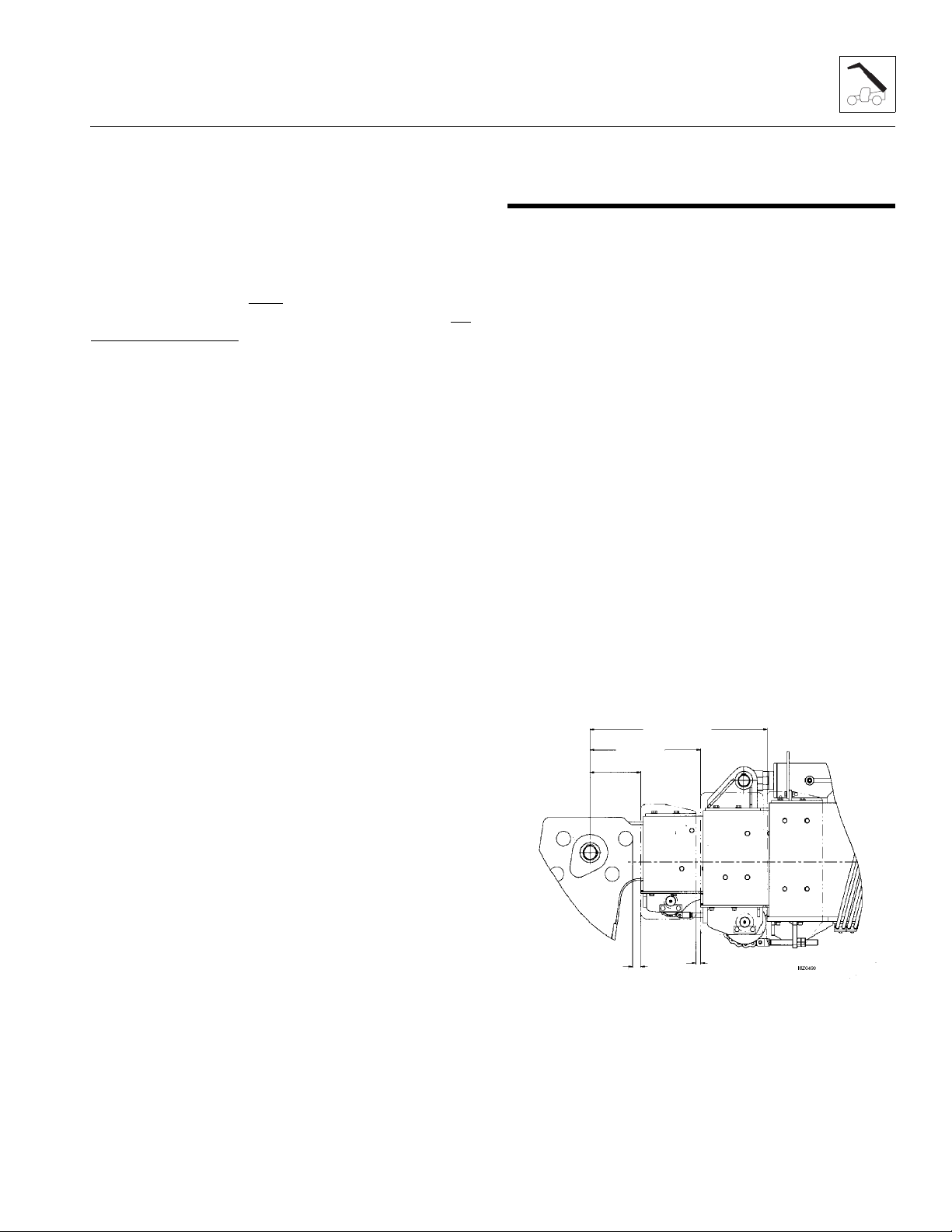
Boom
797mm
31.378”
499mm
19.645”
229mm
9.016”
37mm
1.45”
20mm
.787”
e. Removing Extend and Retract Chains
The four extend chains and the three retract chains can
only be removed during a complete boom teardown.
While doing the chain inspection, check all chain clevis
ends for distortion or cracking and sheaves for bearing
wear or grooving from the chain.
If during the inspection, any chain is found to be damaged
or stretched, the chain must
be replaced. It is
recommended that when any chain is replaced, that all
the chains and clevis’ be replaced at the same time.
3.7.4 Chain Lubrication
After inspection and before being returned to service,
chains must be lubricated with Mystik Tetrimoly Grease.
The lubricant must penetrate the chain joint to prevent
wear. Applying lubricant to the external surfaces will
prevent rust, but the chains should be articulated to
make sure the lubricant penetrates to the working
surfaces between the pins and links.
To prepare the chain for lubrication, the chain plates
should be brushed with a stiff brush or wire brush to
clear the space between the plates so that lubricant can
penetrate to the working surfaces.
Lubricant may be applied with a narrow paint brush or
directly poured on, but the chain should be well flooded
with lubricant and the boom should be extended and
retracted to be sure that the lubricant penetrates to the
working surfaces. All surplus lubricant should be wiped
away from the external surfaces. DO NOT use a solvent
for this wiping operation.
Regular application of lubricant is necessary to make
sure that all working surfaces are adequately lubricated.
In extremely dusty conditions, it may be necessary to
lubricate the chains more often. Refer to Section 2.5,
“Maintenance Schedules,” and Section 2.6, “Lubrication
Schedules,” for detailed information.
Lubrication of chains on vehicles working consistently in
extreme hot or cold conditions requires special
consideration. Contact the local distributor for guidance.
3.8 BOOM SECTION SEPARATION ADJUSTMENT - FOUR SECTION BOOM
The second, third and fourth boom sections are set to
dimensions between each section. The first and second
boom sections are connected by the extend/retract
cylinder which has no adjustment.
The third and fourth boom sections can be adjusted by
loosening or tightening the extend chains and the retract
chains.
1. Fully retract the boom and raise the boom to a
horizontal position. Place the transmission control
lever in (N) NEUTRAL, engage the park brake
switch.
2. Measure the distance between the boom sections. If
adjustments are needed, extend the boom out
0,91 m to 1,2 m (3 ft to 4 ft). Shut off machine.
3. Loosen the locknuts on the extend chains and the
retract chains and adjust as needed.
a. To increase the separation distance: Loosen the
retract chains locknut on the rear of the third or
fourth boom sections one or two turns and
tighten the extend chain loc knuts on the first and
second boom sections equally the same numbe r
of turns. A minimum of one full thread on the
clevis must protrude beyond the locknut.
b. To decrease the separation distance: Loosen the
extend chain locknuts at the front of the first or
second boom sections equally one or two turns
and tighten the retract chains locknut the same
number of turns. A minimum of one full thread
on the clevis must protrude beyond the locknut.
3508PS, 3509PS, 3512PS, 3513PS, 4008PS, 4009PS, 4012PS, 4013PS, 4017PS, 40.8, 40.9
3-21

Boom
MZ1220
120mm - 4.75in
180mm - 7in
4. Start the machine and extend and retract the boom
sections two or three times. Fully retract the boom
and measure the distance between the boom
sections.
5. If the measurements are within the tolerance, tighten
the locknuts on the chain clevises. If more
adjustment is needed, repeat procedure until the
proper boom section dimensions is achieved.
6. With the boom sections within the proper tole ra nce,
start the machine, lower the outriggers if necessary
and extend the boom to maximum extension.
7. Shut the machine off and measure the distance
between the top of both extend chains and the
bottom of the second and third boom sections at the
center of each boom section.
8. The distance between the top of the extend chains
and the bottom of the second boom section should
be approximately 180 mm (7 in). The distance
between the top of the extend chains and the bottom
of the third boom section should be approximately
120 mm (4.75 in).
Note: If the second boom section to the third boom
section separation distance cannot be achieved, contact
the local JLG distributor or the JLG Service Department.
3.9 HOSE CARRIER ASSEMBLY - FOUR SECTION BOOM
3.9.1 Hose Carrier Assembly Removal
1. Remove any attachment from the quick switch
assembly. (Refer to Section 3.11.1, “Connecting with
a Mechanical Quick Switch Device.”)
2. Park the machine on a hard, level surface. Be sure
there is enough room in front and rear of the
machine to extend the boom sections and to be able
to removed the hose carrier from the rear of the
boom assembly.
3. Fully extend the boom and raise the boom to a
horizontal position. Place the transmission control
lever in (N) NEUTRAL, engage the park brake
switch.
4. Retract the boom until the rear hose carrier
mounting bolts on the fourth boom section are
accessible through each side of the third boom
section access holes. Shut off the machine and
remove the bolts.
5. Start the machine and retract the boom until the
middle set of hose carrier bolts on the fourth boom
section are accessible through the third boom
section access holes. Shut the engine OFF and
remove the bolts.
6. Start the engine and retract the boom until the front
set of hose carrier bolts on the fourth boom section
are just in front of the front of the third boom section.
Shut the engine OFF and remove the bolts.
7. Start the engine and slowly retract the boom
sections completely.
8. Shut the engine OFF and place a Do Not Operate
Tag on both the ignition key switch and the steering
wheel, stating that the machine should not be
operated.
9. Relieve any trapped pressure in the tilt hydraulic
system by using the handle provided or a 9mm
wrench and move the double nut on the side of the
main control valve tilt section back and forth. Repeat
on the auxiliary valve section.
10. Locate the two hos es att ach ed to th e ba rr el o f t he tilt
cylinder inside the boomhead.
3-22
3508PS, 3509PS, 3512PS, 3513PS, 4008PS, 4009PS, 4012PS, 4013PS, 4017PS, 40.8, 40.9

11. Label and remove the hoses from the elbow fittings
MZ0900
2
1
MZ0920
3
4
on the tilt cylinder (1). Plug the hose ends and cap
the elbow fittings on the tilt cylinder to prevent dirt
and debris from entering the hydraulic system.
12. Label and remove the two auxiliary hydraulic hoses
(2) from the bulkhead fittings inside the boomhead.
Plug the hose ends and cap the bulkhead fittings to
prevent dirt and debris from entering the hydraulic
system.
13. At the rear of the boom, label and remove the tilt
cylinder hoses and the auxiliary hoses from the hose
carrier bulkhead. Plug the hose ends and cap the
bulkhead fittings to prevent dirt and debris from
entering the hydraulic system.
Boom
15. Remove both left and right side wear pad bolts and
both left and right bottom wear pad bolts from the
rear of the fourth boom section to be able to remove
the hose carrier.
16. Pull the hose carrier halfway out of the rear of the
boom, set on a suitable support. Using a sling
around the hose carrier, balance the hose carrier
and pull the remainder of the way out. Set the hose
carrier on the ground or on suitable supports.
Note: If the machine or the boom has to be moved,
replace all the bolts that were removed from the wear
pads on the rear of the fourth boom section BEFORE the
machine is started and/or the boom is retracted or
extended.
3.9.2 Hose Carrier Assembly Replacement
1. Carefully lay the new hose carrier assembly out flat
on a hard surface.
2. Make sure the boom is level and that the front two
hose carrier holes (5) in the fourth boom section are
accessible just in front of the front of the third boom
section.
3. Using a sling around the center of the hose carrier,
lift and carefully place the front of the hose carrier
part way into the rear of the boom. Set the rear of the
hose carrier down on a suitable support. Reposition
the sling and lift the rear of the hose carrier and slide
it the remainder of the way into the boom.
®
4. Apply Loctite
and install both left and right side wear pads and
bolts and both left and right bottom wear pads and
bolts. torque the side wear pads to 50 Nm (37 lb-ft)
and the bottom wear pads to 90 Nm (66 lb-ft).
243TM to the wear pad mounting bolts
14. From the top rear of the hose carrier, remove both
bolts (3) holding the hose carrier (4) to the third
boom section.
3508PS, 3509PS, 3512PS, 3513PS, 4008PS, 4009PS, 4012PS, 4013PS, 4017PS, 40.8, 40.9
3-23
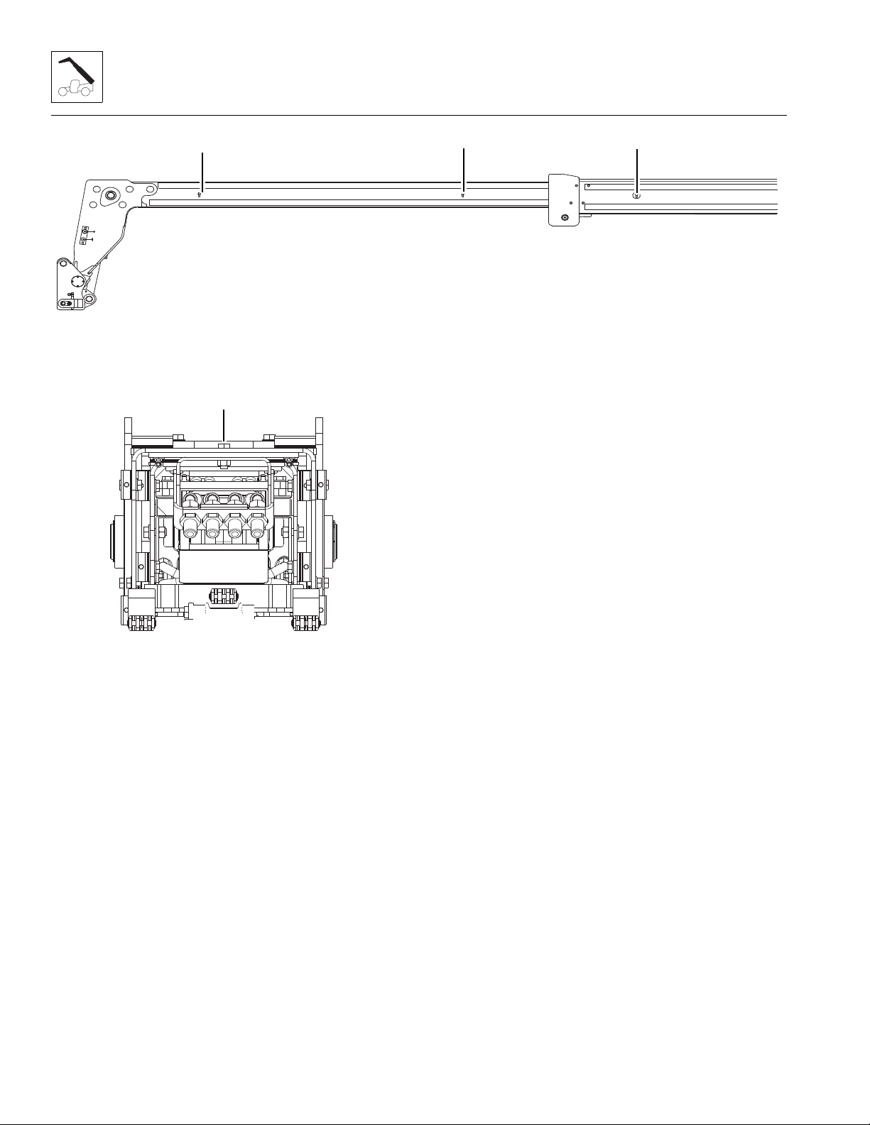
Boom
MZ0910
6
5
7
MZ0920
3
5. Align the front two threaded holes on the hose
carrier with the front two holes (5) on each side of
the fourth boom section and install both bolts. Apply
®
Loctite
243TM and hand tighten only.
6. Fasten the rear of the hose carrier (3) to the top rear
®
of the third boom section. Apply Loctite
243TM and
torque both bolts to 90 Nm (66 lb-ft).
7. Start the machine and extend the boom out until the
middle set of holes (6) in the fourth boom section
align with access holes at the front sides of the third
boom section. Shut off machine.
8. Align the middle two threaded holes on the hose
carrier with the middle two holes on the fourth boom
®
section and install both bolts. Apply Loctite
and hand tighten only.
243TM
9. Start the machine and extend the boom out until the
rear set of holes (7) in the fourth boom section align
with access holes on each side of the third boom
section. Shut off machine.
10. Align the rear two threaded holes on the hose carrier
with the rear two holes on the fourth boom section
®
and install both bolts. Apply Loctite
243TM and
torque to 90 Nm (66 lb-ft).
11. Torque the middle two and front two hose carrier
bolts to 90 Nm (66 lb-ft).
12. Start the machine and retract the boom
completely.Shut the machine off.
13. Relieve any trapped pressure in the tilt hydraulic
system by using the handle provided or a 9mm
wrench and move the double nut on the side of the
main control valve tilt section back and forth. Repeat
on the auxiliary valve section.
14. Attach both tilt cylinder hoses from the hose carrier
to the tilt cylinder and tighten until wrench-tight. Mark
the hose fitting then tighten each hose firmly
1 to 1 1/2 flats.
15. Attach both auxiliary hoses from the hose carrier to
the auxiliary fittings on the bulkhead and tighten until
wrench-tight. Mark the hose fitting then tighten each
hose firmly 1 to 1 1/2 flats.
16. Bolt the auxiliary bulkhead onto the side of the boom
®
head. Apply Loctite
243TM and torque to 50 Nm
(37 lb-ft).
17. At the rear of the boom, attach both tilt cylinder
hoses to the tilt hose carrier bulkhead fittings and
tighten until wrench-tight. Mark the hose fitting then
tighten each hose firmly 1 to 1 1/2 flats.
18. At the rear of the boom, attach both auxiliary hoses
to the auxiliary hose carrier bulkhead fittings and
tighten until wrench-tight. Mark the hose fitting then
tighten each hose firmly 1 to 1 1/2 flats.
19. Start the engine and operate all boom functions
several times. Check for leaks, and check the
hydraulic oil level in the reservoir; add oil if required.
3-24
3508PS, 3509PS, 3512PS, 3513PS, 4008PS, 4009PS, 4012PS, 4013PS, 4017PS, 40.8, 40.9

Boom
Ma2070
1
1
MAM1390
4
3
2
5
MY3620
A
B
3.10 BOOM WEAR PADS
The wear pads on this machine are flat rectangular wear
pads with metal inserts.
A total of 13 wear pads are installed on the boom sections
of the 8 & 9M machines.
A total of 26 wear pads are installed on the boom sections
of the 12 & 13M machines.
A total of 50 wear pads are installed on the boom sections
of the 17M machines.
3.10.1 Wear Pad Inspection
Inspect all wear pads for wear. If the angle indicators (1)
on the ends of the wear pads are visible, the wear pads
can be reused. If the pads show uneven wear (front to
back), they should be replaced. Replace pads as a set if
worn or damaged.
• The number of shims can vary at each shim point.
• The bottom wear pads must be shimmed equally on
each side.
• Maintain a total boom section clearance (5) of
1,78 - 3,30 mm (0.070 - 0.130 in) both the horizontal
and vertical directions.
3.10.2 Wear Pad Installation and Lubrication
Note: Inspect all wear pads. Replace as necessary.
The following wear pad procedure must be followed to
insure the proper wear pad installation:
• The wear pad inserts and mounting bolts MUST be
clean from any grease, oil or other contaminates
before applying Loctite
mounting bolts.
• Apply Loctite
®
243TM to all wear pad mounting bolts.
®
243TM and installing
• The length of the wear pad bolt depends on the
number of shims, spacers and washers being used.
• The thickness of each threaded wear pad insert is
7,92 mm (0.312 in) (A).
• The bolt length should be determined by measuring
the distance from the face of the insert to the face of
the boom (B) including any spacer, shim(s) and
washer(s).
• Bolt thread engagement in the wear pad insert
should be 6,98 ± 1,0 mm (0.275 ± 0.040 in).
• One or two hardened washers are to be used on
each wear pad bolt except where noted otherwise.
DO NOT use more than two hardened washers.
• Use only o ne h arde ned was her i f mo unt ing bol ts are
recessed.
• Wear Pad Bolt Torque:
M8x25 Bolt, 50 Nm (37 lb-ft)
M8x30 Bolt, 50 Nm (37 lb-ft)
M10x20 Bolt, 50 Nm (37 lb- ft)
M10x22 Bolt, 50 Nm (37 lb- ft)
M10x25 Bolt, 50 Nm (37 lb- ft)
M10x30 Bolt, 50 Nm (37 lb- ft)
M10x35 Bolt, 50 Nm (37 lb- ft)
M10x40 Bolt, 50 Nm (37 lb- ft)
• A spacer (2) with holes must be used before any
shim (3) is used.
• A shim (3) must be inserted between the spacer (2)
and wear pad support plate, block or boom section
(4).
M12x20 Bolt, 90 Nm (66 lb- ft)
M12x25 Bolt, 90 Nm (66 lb- ft)
M12x30 Bolt, 90 Nm (66 lb- ft)
M12x35 Bolt, 90 Nm (66 lb- ft)
M12x40 Bolt, 90 Nm (66 lb- ft)
3508PS, 3509PS, 3512PS, 3513PS, 4008PS, 4009PS, 4012PS, 4013PS, 4017PS, 40.8, 40.9
3-25

Boom
9
8
7
6
MAH0980
10
• Torque wear pad bolts after shimming is completed.
• Lubricate the face and pockets of each wear pad
after being installed.
Boom Section Wear Pad Pathway Lubrication:
• Clean and lightly grease all wear pad pathways with
Mystik Tetrimoly grease.
• Clean and lightly grease the hose carrier guide bar
pathways with Mystik Tetrimoly grease.
3.11 QUICK SWITCH ASSEMBLY
This machine is equi ppe d with a qui ck sw i tch sy st em for
easy attachment changes.
3.1 1.1 Connecting with a Mechanical Quick Switch Device
3.11.2 Connecting with a Hydraulic Quick Switch Device
1. Retract quick switch device to provide clearance.
Check to be sure lock pin is disengaged.
2. Align attachment pin (8) with recess in
attachment (9). Raise boom slightly to engage
attachment pin in recess.
3. Engage quick switch device.
4. Press the button (10) and at the same time, move
the joystick to engage or to disengage the quick
switch device.
5. Raise the boom to eye level and visually check that
the quick switch pin protrudes through the hole. If
the pin does not protrude through the hole, place the
attachment on the ground and return to step 2.
6. If attachment is equipped, connect auxiliary
hydraulic hoses. See Section 3.11.3, “Connecting
with a Quick Switch to a Hydraulic Operated
Attachment.”
1. Retract quick switch device to provide clearance.
Check to be sure lock pin (6) and retainer pin (7) is
out.
2. Align attachment pin (8) with recess in
attachment (9). Raise boom slightly to engage
attachment pin in recess.
3. Engage quick switch device.
4. Shut off engine. Exit cab and insert lick pin and
secure with retainer pin.
5. If attachment is equipped, connect auxiliary
hydraulic hoses. See Section 3.11.3, “Connecting
with a Quick Switch to a Hydraulic Operated
Attachment.”
3.1 1.3 Connecting with a Quick Switch to a Hydraulic Operated Attachment
1. Lower attachment to ground. Set parking brake, shut
off engine and turn key back to the “ON” position.
2. Relieve pressure in the hydraulic system by
actuating the joystick.
3. Connect the quick-disconnect fittings.
4. Start the engine.
3-26
3508PS, 3509PS, 3512PS, 3513PS, 4008PS, 4009PS, 4012PS, 4013PS, 4017PS, 40.8, 40.9

Boom
13
12
11
MH6460
3
2
6
7
5
1
4
9
8
10
11
3.11.4 Quick Switch Removal
3.12 FORKS
Forks should be cleaned and inspected prior to being
attached to carriage. If the following criteria is not met,
forks must be removed from service immediately.
Daily Inspection
1. Support the quick switch assembly. Remove the lock
bolt (11) holding the tilt cylinder rod end pin (12) to
the quick switch assembly. Remove the tilt cylinder
pin.
2. Support the quick switch assembly . Remove the four
bolts and covers (13) from each end of the quick
switch assembly. Remove the pin from the quick
switch assembly from either side.
3. Inspect the above pin for nicks or surface corrosion.
Use fine emery cloth to fix minor nicks or corrosion.
If damaged or if it cannot be repaired, the pin must
be replaced.
3.11.5 Quick Switch Installation
1. Assemble the quick switch to the boom head. Line
up the quick switch between the mounts on the
boom head. The quick switch should be centered in
the boom head.
2. Coat the quick switch pivot pin with an anti-seize
compound. Insert the quick switch pivot pin through
the quick switch and boom head. Replace the end
covers and four bolts (10) to each end of the quick
switch.
3. Align the quick switch with the tilt cylinder rod end
and insert the tilt cylinder pin. Align the tilt cylinder
pin and screw in the locking bolt (9). Torque as
required.
1. Inspect forks (1) for cracks, paying special attention
to heel (2) and mounting tubes (3).
2. Inspect forks for broken or bent tips (4) and twisted
blades (5) and shanks (6).
Yearly Inspection
1. Straightness of the upper face of blade (5) and the
front face of shank (6) should not exceed 0.5 percent
of the length of blade or height of shank.
2. Angl e (7) between upper face of blade and front face
of shank should not exceed 93 degrees.
3. Thickness of blade (8) and shank (9) should not be
reduced to 90 percent of original thickness.
Note: Contact the local distributor with the fork part
number to find the manufactured dimensions of the fork
blade.
4. Ensure fork length (10) is adequate for intended
loads.
5. Fork markings should be legible, re-st amp if
required.
6. Compare fork tips (11) when mounted on a carriage.
Maximum dif fer ence in hei ght of f ork tips is 3 perce nt
of the length of the blade (10).
3-27
3508PS, 3509PS, 3512PS, 3513PS, 4008PS, 4009PS, 4012PS, 4013PS, 4017PS, 40.8, 40.9

Boom
3.13 TROUBLESHOOTING
This section provides an easy reference guide covering
the most common problems that occur during operation
of the boom.
Problem Cause Remedy
1. Boom will not extend or
retract
2. Boom will not fully extend. 1. Extend/retract hydraulic system
3. Boom shifts to right or left
when extending.
4. Excessive pivot pin noise
and/or wear.
1. Broken hydraulic hose(s) or
tube(s) and/or connections
leaking.
2. Extend/retract hydraulic system
not operating properly.
3. Faulty extend/retract cylinder. 3. Repair cylinder. Refer to Section
not operating properly.
1. Boom side wear pads
improperly shimmed or worn.
1. Insufficient lubrication. 1. Lubricate at regular intervals.
2. Worn bearing(s). 2. Replace bearing(s) and
1. Locate break, replace hose(s)
or tube(s), tighten connections.
2. Refer to Section 8, “Hydraulic
System.”
8.10.4, “Cylinder Inspection.”
1. Refer to Section 8, “Hydraulic
System.”
1. Shim wear pads to correct gap.
Replace wear pads as needed.
Refer to Section 3.10.2, “Wear
Pad Installation and
Lubrication.”
Refer to Section 2.6,
“Lubrication Schedules.”
Replace worn pins as needed.
lubricate at regular intervals
Refer to Section 2.6,
“Lubrication Schedules.”
5. Boom will not raise or lower. 1. Broken hydraulic hoses or tubes
and/or connection leaks .
2. Lift/lower hydraulic system not
operating properly.
3. Faulty lift/lower cylinder. 3. Repair cylinder. Re fer t o Section
4. Seized boom pivot pin bearing. 4. Replace beari ng.
3-28
3508PS, 3509PS, 3512PS, 3513PS, 4008PS, 4009PS, 4012PS, 4013PS, 4017PS, 40.8, 40.9
1. Locate break, replace hose(s)
or tube(s), tighten connections.
2. Refer to Section 8, “Hydraulic
System.”
8.10.4, “Cylinder Inspection.”

Boom
Problem Cause Remedy
6. Rapid boom pad wear. 1. Incorrect wear pad gap. 1. Check wear pad gaps and
correct as needed. Refer to
Section 3.10.2, “Wear Pad
Installation and Lubrication.”
7. Auxiliary hydraulics will not
operate.
2. Rapid cycle times with heavy
loads.
3. Contaminated, corroded or
rusted wear pad sliding
surfaces.
4. Operating in extremely dusty/
abrasive conditions.
1. Auxiliary hydraulic system not
operating properly.
2. Reduce cycle times.
3. Remove contamin ation and/or
corrosion from wear pad sliding
surfaces an d lubricate. If the
surfaces cannot be
reconditioned, replace the boom
section(s).
4. Clean equipment frequently.
1. Refer to Section 8, “Hydraulic
System.”
3508PS, 3509PS, 3512PS, 3513PS, 4008PS, 4009PS, 4012PS, 4013PS, 4017PS, 40.8, 40.9
3-29

Boom
This Page Intentionally Left Blank
3-30
3508PS, 3509PS, 3512PS, 3513PS, 4008PS, 4009PS, 4012PS, 4013PS, 4017PS, 40.8, 40.9

Section 4
Cab and Covers
Contents
PARAGRAPH TITLE PAGE
4.1 Operator Cab and Covers Component Terminology . . . . . . . . . . . . . . . . . . . . . . 4-2
4.2 Operator Cab . . . . . . . . . . . . . . . . . . . . . . . . . . . . . . . . . . . . . . . . . . . . . . . . . . . . . . 4-3
4.2.1 Serial Number Decal. . . . . . . . . . . . . . . . . . . . . . . . . . . . . . . . . . . . . . . . . 4-3
4.3 Cab Components. . . . . . . . . . . . . . . . . . . . . . . . . . . . . . . . . . . . . . . . . . . . . . . . . . . 4-3
4.3.1 Steering Column and Orbitrol Valve . . . . . . . . . . . . . . . . . . . . . . . . . . . . . 4-3
4.3.2 Service Brake Pedal and Valve. . . . . . . . . . . . . . . . . . . . . . . . . . . . . . . . . 4-4
4.3.3 Throttle Pedal Replacement . . . . . . . . . . . . . . . . . . . . . . . . . . . . . . . . . . . 4-4
4.3.4 Joystick Assembly Replacement. . . . . . . . . . . . . . . . . . . . . . . . . . . . . . . . 4-5
4.3.5 Parking Brake (8, 9, 12 & 13M). . . . . . . . . . . . . . . . . . . . . . . . . . . . . . . . . 4-6
4.3.6 Parking Brake (17M) . . . . . . . . . . . . . . . . . . . . . . . . . . . . . . . . . . . . . . . . . 4-7
4.3.7 Windshield Wiper Assembly . . . . . . . . . . . . . . . . . . . . . . . . . . . . . . . . . . . 4-7
4.3.8 Windshield Washer Assembly. . . . . . . . . . . . . . . . . . . . . . . . . . . . . . . . . . 4-7
4.3.9 Heater/Defroster System. . . . . . . . . . . . . . . . . . . . . . . . . . . . . . . . . . . . . . 4-8
4.3.10 Cab Heater/Air Conditioning Controls. . . . . . . . . . . . . . . . . . . . . . . . . . . . 4-9
4.4 Cab Removal . . . . . . . . . . . . . . . . . . . . . . . . . . . . . . . . . . . . . . . . . . . . . . . . . . . . . . 4-9
4.5 Cab Installation . . . . . . . . . . . . . . . . . . . . . . . . . . . . . . . . . . . . . . . . . . . . . . . . . . . . 4-11
3508PS, 3509PS, 3512PS, 3513PS, 4008PS, 4009PS, 4012PS, 4013PS, 4017PS, 40.8, 40.9
4-1

Cab and Covers
MZ2061
DISPLAY
PANEL
LOAD STABILITY
INDICATOR
JOYSTICK
HEATER & AC
CONTROLS
BRAKE FLUID
RESERVOIR
TRANSMISSION
CONTROL LEVER
SERVICE BRAKE
PEDAL
PARKING BRAKE
LEVER
ACCELERATOR
PEDAL
POWER/
EMERGENCY
STOP SWITCH
(IF EQUIPPED)
IGNITION
4.1 OPERATOR CAB AND COVERS COMPONENT TERMINOLOGY
To understand the safety, operation and maintenance
information presented in this section, it is necessary that
the operator/mechanic be familiar with the names and
locations of the major assemblies of the machine cab and
covers. The following illustration identifies the
components that are referred to throughout this section.
4-2
3508PS, 3509PS, 3512PS, 3513PS, 4008PS, 4009PS, 4012PS, 4013PS, 4017PS, 40.8, 40.9
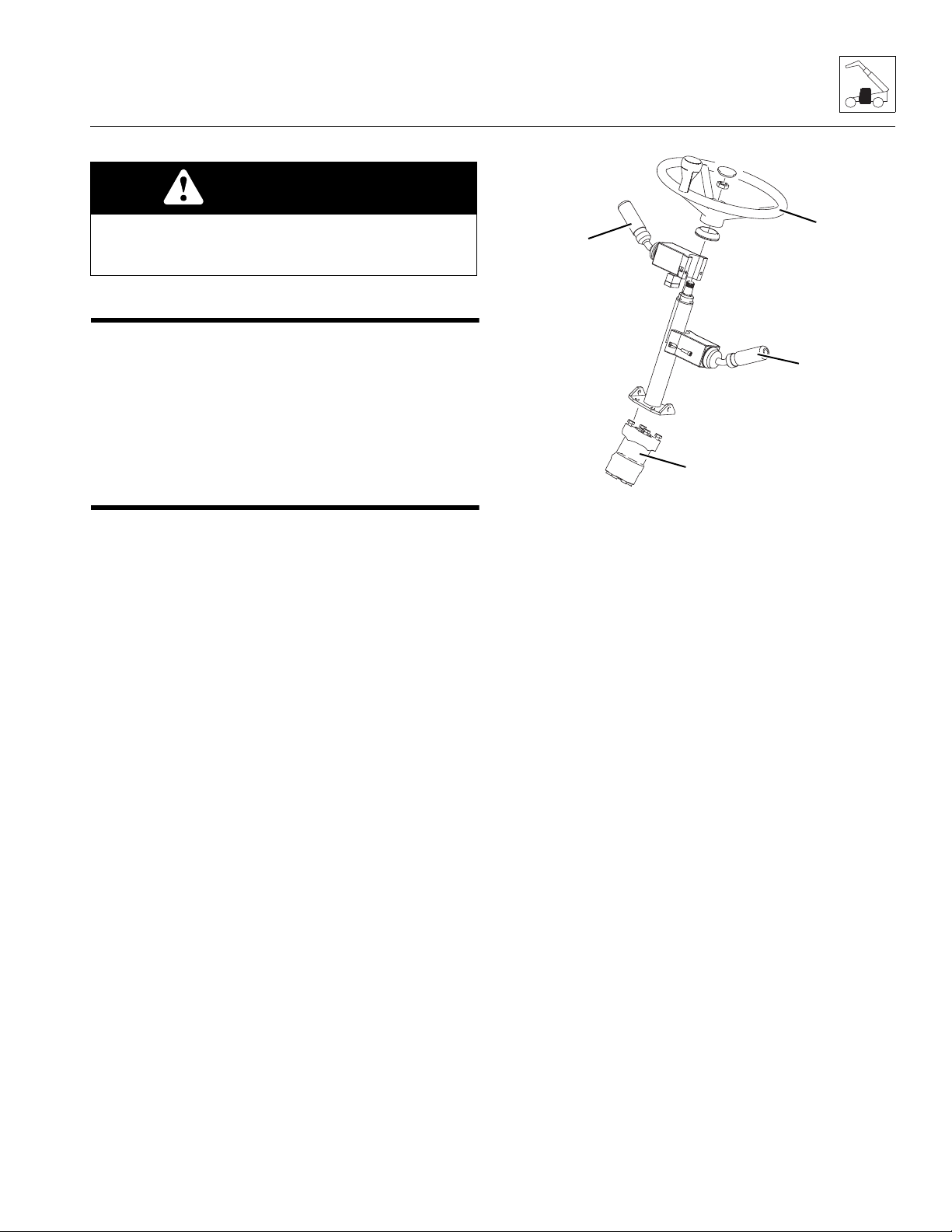
WARNING
MZ2000
1
2
3
4
DO NOT service the machine without following all
safety precautions as outlined in the “Safety
Practices” section of this manual.
4.2 OPERATOR CAB
4.2.1 Serial Number Decal
The cab serial number decal is located inside the cab,
behind the seat. Information specified on the serial
number plate includes the cab model number, the cab
serial number and other data. Write this information down
in a convenient location to use in cab correspondence.
4.3 CAB COMPONENTS
4.3.1 Steering Column and Orbitrol Valve
a. Orbitrol Valve Removal
1. Park the machine on a firm, level surface, level the
machine, fully retract the boom, lower the boom,
place the transmission control lever in
(N) NEUTRAL, engage the park brake and shut the
engine OFF.
2. Place a Do Not Operate T ag on both the ignition key
switch and steering wheel, stating that the machine
should not be operated.
3. Open the engine cover. Allow the system fluids to
cool.
4. Properly disconnect the battery.
5. Remove the lower dash panel.
6. Remove the steering adjustment lever.
Cab and Covers
7. Label, disconnect and cap the hydraulic hoses
attached to the steering valve (1). Cap all fittings to
prevent dirt and debris from entering the hydraulic
system.
8. Remove the steering wheel (2), disconnect and
remove the accessory control lever (3) and
transmission control lever (4).
9. Support the steering valve, and remove the four hexhead capscrews and four lockw ash ers.
10. Remove the steering assembly from the dash panel.
Note: DO NOT disassemble the orbitrol valve. The
orbitrol valve is not serviceable and must be replaced in
its entirety, if defective.
b. Orbitrol Valve Installation
1. Install the steering valve and steering column to their
original orientation on the steering bracket with four
hex-flange capscrews and four lockwashers.
2. Install the accessory control lever and transmission
control lever and connect the harness connector,
install the steering wheel assembly. Torque the
steering wheel nut to 40 Nm (29.5 lb-ft).
Note: ALWAYS use new o-rings when servicing the
machine.
3. Install new o-rings into the fittings. Lubricate the orings with clean hydraulic oil.
4. Uncap and connect the previously labeled hoses to
3508PS, 3509PS, 3512PS, 3513PS, 4008PS, 4009PS, 4012PS, 4013PS, 4017PS, 40.8, 40.9
the appropriate ports.
5. Install the steering adjustment lever.
6. Properly connect the battery.
4-3

Cab and Covers
MZ1960
5
7. Start the engine and check the operation of steering
system. Check for hydraulic oil leaks. Check the
hydraulic oil level in the tank and add oil as required.
Wipe up any spilled oil.
8. Install the lower dash panel.
9. Close and secure the engine cover.
10. Remove the Do Not Operate Tags from both the
ignition key switch and the steering wheel.
c. Power Steering Test
Conduct a pressure check of the steering hydraulic
circuits at the main control valve. Refer to Section 8.4.1,
“Hydraulic Pressures.”
4.3.2 Service Brake Pedal and Valve
a. Service Brake Valve
Refer to Section 8.9.2, “Service Brake Valve,” for removal
and installation information.
b. Service Brake Pedal Removal
1. Park the machine on a firm, level surface, level the
machine, fully retract the boom, lower the boom,
place the transmission control lever in
(N) NEUTRAL, engage the park brake and shut the
engine OFF.
2. Place a Do Not Operate Tag on both the ignition key
switch and steering wheel, stating that the machine
should not be operated.
3. Open the engine cover. Allow the system fluids to
cool.
4. Properly disconnect the battery.
5. Remove the lower dash panel.
6. Remove the circlip, flat washer, bushing and the
return spring securing the service brake pedal to the
cab.
7. Remove the clip/pin from the brake plunger fork link.
8. Remove the service brake pedal (5) from the cab.
c. Service Brake Pedal Installati on
1. Position the service brake pedal in its mounting
location within the cab.
2. Install the brake pedal being careful to reposition th e
brake plunger yoke. Install the return spring , washer,
bushing and clip. Install clip/pin in brake plunger fork link.
3. Adjust the brake pedal as needed.
4. Install and secure th e low er dash cover.
5. Properly connect the battery.
6. Close and secure the engine cover.
7. Remove the Do Not Operate Tags from both the
ignition key switch and the steering wheel.
4.3.3 Throttle Pedal Replacement
a. Throttle Pedal Removal
1. Park the machine on a firm, level surface, level the
machine, fully retract the boom, lower the boom,
place the transmission control lever in
(N) NEUTRAL, engage the park brake and shut the
engine OFF.
2. Place a Do Not Operate Tag on both the ignition key
switch and steering wheel, stati ng that the machi ne
should not be operated.
3. Open the engine cover. Allow the engine to cool.
4. Properly disconnect the battery.
5. Remove the lower dash panel.
4-4
3508PS, 3509PS, 3512PS, 3513PS, 4008PS, 4009PS, 4012PS, 4013PS, 4017PS, 40.8, 40.9

6. Remove the throttle pedal return spring (6).
MZ1970
6
7
MZ2030
8
9
7. Disconnect the throttle control cable (7) from the
throttle lever.
8. Remove the retaining ring from the throttle pedal
pivot pin. Slide the throttle pedal, bushings and
washers off the pivot pin.
9. Remove the throttle pedal assembly from the cab.
10. If a new throttle cable is required, remove the cable
connector from the engine. Route the cable through
the bottom of the cab and remove from the machine.
Note the routing path for installation.
b. Throttle Pedal Installation
1. If required, install a new throttle cable to the engine
connection and route cable to cab following the
previous routing path.
2. Slide the throttle pedal, bushings and washers onto
the throttle pedal pivot pin. Secure with retaining
ring.
3. Connect the throttle control cable to the throttle
lever.
4. Install the throttle pedal return spring.
5. Properly connect the battery.
Cab and Covers
2. From within the cab, check the engine rpm at low
idle. If the rpm is not 925 ±50 rpm, readjust the
throttle cable adjustments.
3. Check the engine rpm at full throttle. If the rpm is not
2340 ±50 rpm, adjust the rubber-stop screw on the
throttle pedal or the throttle cable adjustments.
Note: During the full throttle check:
• DO NOT operate any hydraulic function.
• DO NOT steer or apply any pressure to the
steering wheel.
• Keep the transmission in (N) NEUTRAL.
4. Close and secure the engine cover.
5. Remove the Do Not Operate Tags from both the
ignition key switch and the steering wheel.
4.3.4 Joystick Assembly Replacement
a. Joystick Assembly Removal
1. Park the machine on a firm, level surface, level the
machine, fully retract the boom, lower the boom,
place the transmission control lever in
(N) NEUTRAL, engage the park brake and shut the
engine OFF.
2. Place a Do Not Operate Tag on both the ignition key
switch and steering wheel, stating that the machine
should not be operated.
3. Open the engine cover. Allow the engine to cool.
4. Properly disconnect the battery.
c. Throttle Adjustment
1. Adjust the distance on each end of the throttle cable
from the locknut to the connector end. The distance
from the connector to the locknut in the cab should
be 129 mm (5 in). In the engine compartment, the
distance should be 234 mm (9.2 in).
Note: These measurements are to be used as starting
points. If furth er adjus tment is requi red, th e dista nce may
need to be altered.
3508PS, 3509PS, 3512PS, 3513PS, 4008PS, 4009PS, 4012PS, 4013PS, 4017PS, 40.8, 40.9
5. Remove the capscrews securing the bottom cover
(8). Disconnect the electrical connections and
remove the four self-tapping screws from the bottom
of the joystick assembly.
6. Remove the joystick assembly (9).
4-5
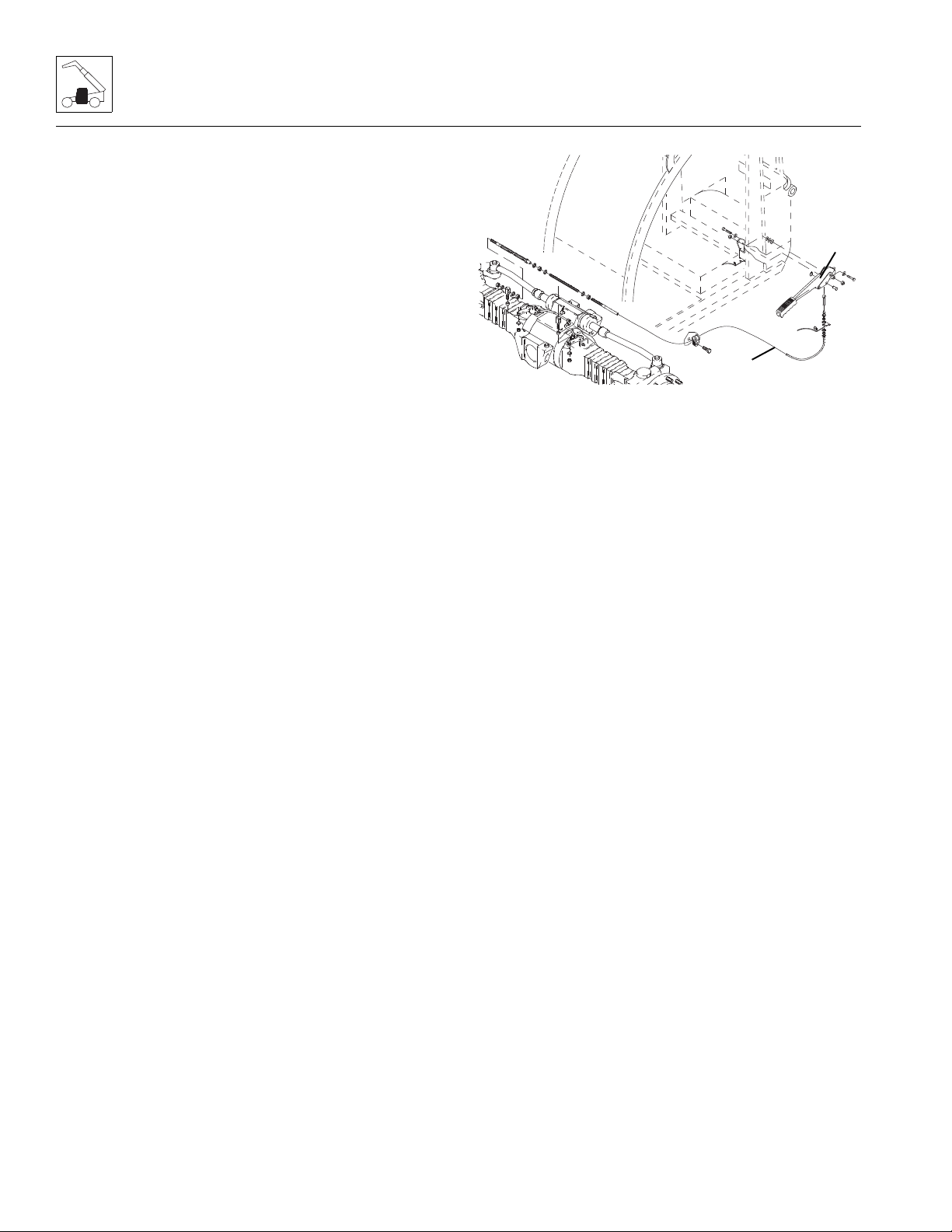
Cab and Covers
MZ1490
1
2
b. Joystick Assembly Installation
1. Set the joystick assembly into the armrest support.
2. Install the four self-tapping screws. Connect the
electrical connections.
3. Properly connect the battery.
4. Test the boom joystick functions:
a. Move the joystick handle rearward, activating the
boom lift function. The boom should RISE.
b. Move the joystick handle forward, activating the
boom lower function. The boom should LOWER.
c. Move the joystick handle to the right, activating
the boom extend function. The boom should
EXTEND.
d. Move the joystick handle to the left, activating the
boom retract function. The boom should
RETRACT.
e. Move the joystick rocker switch forward
activating the boom extend function. The boom
should EXTEND.
5. Install the bottom cover.
6. Close and secure the engine cover.
7. Remove the Do Not Oper ate Tags from both the
ignition key switch and the steering wheel.
4.3.5 Parking Brake (8, 9, 12 & 13M)
a. Park Brake Removal
1. Park the machine on a firm, level surface, level the
machine, fully retract the boom, lower the boom,
place the transmission control lever in (N)
NEUTRAL, engage the park brake and shut the
engine OFF.
2. Place a Do Not Operate Tag on both the ignition key
switch and the steering wheel, stating that the
machine should not be operated.
3. Open the engine cover. Allow the system fluids to
cool.
4. Block the wheels.
5. Properly disconnect the battery.
6. Remove the cover from around the park brake lever.
7. Remove the pin attached to the park brake cable (1)
from the park brake lever (2).
8. Remove the bolts holding the park brake lever to the
mounting plate.
9. Loosen the nuts securing the park brake cable to the
mounting plate.
10. Feed the cable end through the bottom of the cab.
1 1. If necessary, remove the cable clamp from under the
cab.
Note: Record the routing of the park brake cable for
later installation.
12. Remove the cable mounting hardware on the front
axle to free the park brake cable.
b. Park Brake Installation
1. Install the park brake cable on the front axle.
2. Route the park brake cable using the previous
routing path.
3. Feed the cable end through the bottom of the cab.
4. Secure the park brake lever to the mounting plate
using the pre-existing mounting hardware.
5. Secure the park brake cable to the park brake lever
with the pre-existing pin.
6. Connect the park brake electrical connector switch.
7. Properly connect the battery.
8. Test the park brake for proper functionality.
9. With the park brake applied, check the display panel
for the proper indicator light.
10. Reinstall the cover around the park brake lever.
11. Unblock the wheels.
12. Close and secure the engine cover.
13. Remove the Do Not Operate Tags from both the
ignition key switch and the steering wheel.
4-6
3508PS, 3509PS, 3512PS, 3513PS, 4008PS, 4009PS, 4012PS, 4013PS, 4017PS, 40.8, 40.9
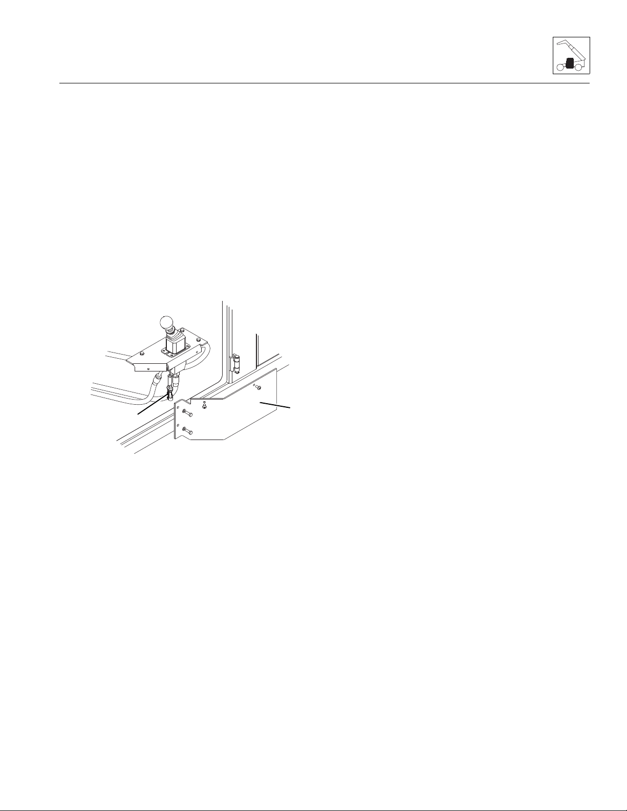
Cab and Covers
MZ2020
3
4
4.3.6 Parking Brake (17M)
a. Park Brake Removal
1. Park the machine on a firm, level surface, level the
machine, fully retract the boom, lower the boom,
place the transmission control lever in (N)
NEUTRAL, engage the park brake and shut the
engine OFF.
2. Place a Do Not Operate T ag on both the ignition key
switch and the steering wheel, stating that the
machine should not be operated.
3. Open the engine cover. Allow the system fluids to
cool.
4. Block the wheels.
5. Properly disconnect the battery.
2. Uncap and connect the previously labeled hydraulic
hoses to the park brake.
3. Connect the park brake electrical connector switch.
4. Check the routing of all hoses for sharp bends or
interference with any rotating members, and install
tie wraps and/or protective conduit as required.
5. Start the engine and run at approximately 30-50%
throttle for about one minute, without moving the
machine or operating any hydraulic functions.
6. Bleed air from the brake circuit. Refer to Section
8.9.3, “Brake Test.”
7. Inspect the park brake valve and connections for
leaks, and check the level of the hydraulic oil in the
reservoir. Shut the engine OFF.
8. With the park brake applied, check the display panel
for the proper indicator light.
9. Wipe up any hydraulic oil spillage in, on, near and
around the machine, work area and tools.
10. Reinstall the cover around the park brake lever.
11. Properly connect the battery.
12. Unblock the wheels.
13. Close and secure the engine cover.
14. Remove the Do Not Operate Tags from both the
ignition key switch and the steering wheel.
6. Remove the cover (3) from around the park brake
lever.
7. Disconnect the park brake electrical connector
switch (4).
8. Label, disconnect and cap the hydraulic hoses
attached to the park brake. Cap all fittings to prevent
dirt and debris from entering the hydraulic system.
9. Remove the bolts holding the park brake lever to the
mounting plate.
Note: DO NOT disassemble the park brake valve. The
valve is not serviceable and must be replaced in its
entirety, if defective.
b. Park Brake Installation
1. Secure the park brake lever to the mounting plate
using the pre-existing mounting hardware.
Note: ALWAYS replace seals, o-rings, gaskets, etc.,
with new parts to help ensure proper sealing and
operation. Lubricate seals and o-rings with clean
hydraulic oil.
4.3.7 Windshield Wiper Assembly
Refer to Section 9.12.1, “Windshield Wiper Motor,” for
removal and installation information.
4.3.8 Windshield Washer Assembly
Refer to Section 9.12.3, “Windshield Washer Reservoir
and Pump,” for removal and installation information.
3508PS, 3509PS, 3512PS, 3513PS, 4008PS, 4009PS, 4012PS, 4013PS, 4017PS, 40.8, 40.9
4-7

Cab and Covers
MZ2050
5
MZ2040
6
7
4.3.9 Heater/Defroster System
a. Heater Assembly Removal
1. Park the machine on a firm, level surface, level the
machine, fully retract the boom, lower the boom,
place the transmission control lever in
(N) NEUTRAL, engage the park brake and shut the
engine OFF.
2. Place a Do Not Operate Tag on both the ignition key
switch and the steering wheel, stating that the
machine should not be operated.
3. Open the engine cover. Allow the system fluids to
cool.
4. Properly disconnect the battery.
5. Remove the belly pan.
6. Slowly turn the radiator cap to the first stop and allow
any pressure to escape. Remove the radiator cap.
7. Place a funnel at the base of the radiator to channel
the drained coolant into the container. Loosen the
drain plug and slowly remove to allow the coolant to
drain. Transfer the coolant into a suitable, covered
container and label as "Used Coolant". Dispose of
the used coolant at an approved recycling facility.
Clean and reinstall the drain plug.
10. Loosen the hose clamps and disconnect the heater
hoses (6).
11. Remove the heat duct hoses (7) from the back side
of the heating unit assembly.
12. Label and disconnect the electrical connectors
attached to the heater assembly.
13. Remove the heater assembly mounting bolts.
14. Carefully lift the heater assembly and remove from
the cab.
8. Remove the cab bottom and heater shield (5).
9. Remove the cab floor mat to gain access to the
heater assembly mounting bolts.
Note: Label all hoses to ensure correct installation.
b. Heater Assembly Installation
1. Lower the heater assembly into the cab to its original
orientation. Secure with the previou sl y used
hardware.
2. Connect the wiring harness connections to the
blower.
3. Connect the previously labeled hoses to the heater.
Secure with hose clamps.
4. Fill the cooling system completely with cool ant,
allowing time for the coolant to fill the engine block.
The cooling system capacity is listed in Section 2.4,
“Fluids, Lubricants and Capacities.”
5. Properly connect the battery.
6. Start the engine and run at low idle. Check for any
visual signs of fluid leakage. STOP the engine
immediately if any leakage is noted, and make any
necessary repairs before continuing.
7. Wait for the engine to cool and check the coolant
level. Add coolant to the overflow bottle as required
to bring the coolant to the proper level.
8. Replace the cab bottom and heater shield.
4-8
3508PS, 3509PS, 3512PS, 3513PS, 4008PS, 4009PS, 4012PS, 4013PS, 4017PS, 40.8, 40.9

Cab and Covers
MAM0310
8
8
9
9. Replace the belly pan.
10. Close and secure the engine cover.
11. Remove the Do Not Operate Tags from both the
ignition key switch and the steering wheel.
4.3.10 Cab Heater/Air Conditioning Controls
a. Cab Heater Controls Removal
1. Park the machine on a firm, level surface, level the
machine, fully retract the boom, lower the boom,
place the transmission control lever in
(N) NEUTRAL, engage the park brake and shut the
engine OFF.
2. Place a Do Not Operate T ag on both the ignition key
switch and the steering wheel, stating that the
machine should not be operated.
3. Open the engine cover. Allow the system fluids to
cool.
4. Properly disconnect the battery.
5. Remove the plastic side cover in the cab to gain
access to the control cables and electronics. If
necessary, remove the seat for more accessibility.
c. Installation and Testing
1. Install the control box into the dash panel until the
side clips firmly hold the box.
2. Connect the previously labeled electrical connectors
to the appropriate locations.
3. Connect the previously labeled control cables to the
appropriate control knob mechanisms.
4. Properly connect the battery.
5. Turn the ignition key to the ON position and check
the control functions.
6. Start the machine and allow engine to warm to
operating temperature. Check heat control at
different levels.
7. Install the plastic side cover. If necessary, install the
seat.
8. Close and secure the engine cover.
9. Remove the Do Not Operate Tags from both the
ignition key switch and the steering wheel.
4.4 CAB REMOVAL
Note: To help ensure safety and optimum performance,
replace the cab if it is damaged. Refer to the appropriate
parts manual for ordering information.
6. Label and disconnect the control cables (8) attached
to the control knob mechanisms.
7. Label and disconnect the electrical connectors
attached to the control box.
8. Depress the side clips (9) and push the control box
through the dash panel.
b. Disassembly
DO NOT disassemble the cab heater and fan controls.
The controls are not serviceable. Replace controls if
found to be defective.
Before performing any inspection, maintenance or
service operation, thoroughly clean the machine. DO
NOT spray water or cleaning solution in, on, near or
around the operator dash panels and electrical
components.
Inspect the cab, its welds and mounts. If modification,
damage, a cracked weld and/or fatigued metal is
discovered, replace the cab. Contact your local aut hor ized
service distributor with any questions about the suitability
or condition of a cab.
Note: Remove and label cab components as needed
before removing the cab from the machine. Label,
disconnect and cap hydraulic hoses. Transfer cab parts
to the replacement cab after the replacement cab is
securely mounted on the machine.
1. Park the machine on a firm, level surface, level the
machine. Allow sufficient overhead and side
clearance for cab removal. Fully retract the boom,
lower the bo om, plac e the tr an smi ssion contr ol lever
in (N) NEUTRAL, engage the park brake and shut
the engine OFF.
2. Block the wheels.
3. Open the engine cover. Allow the system fluids to
cool.
3508PS, 3509PS, 3512PS, 3513PS, 4008PS, 4009PS, 4012PS, 4013PS, 4017PS, 40.8, 40.9
4-9
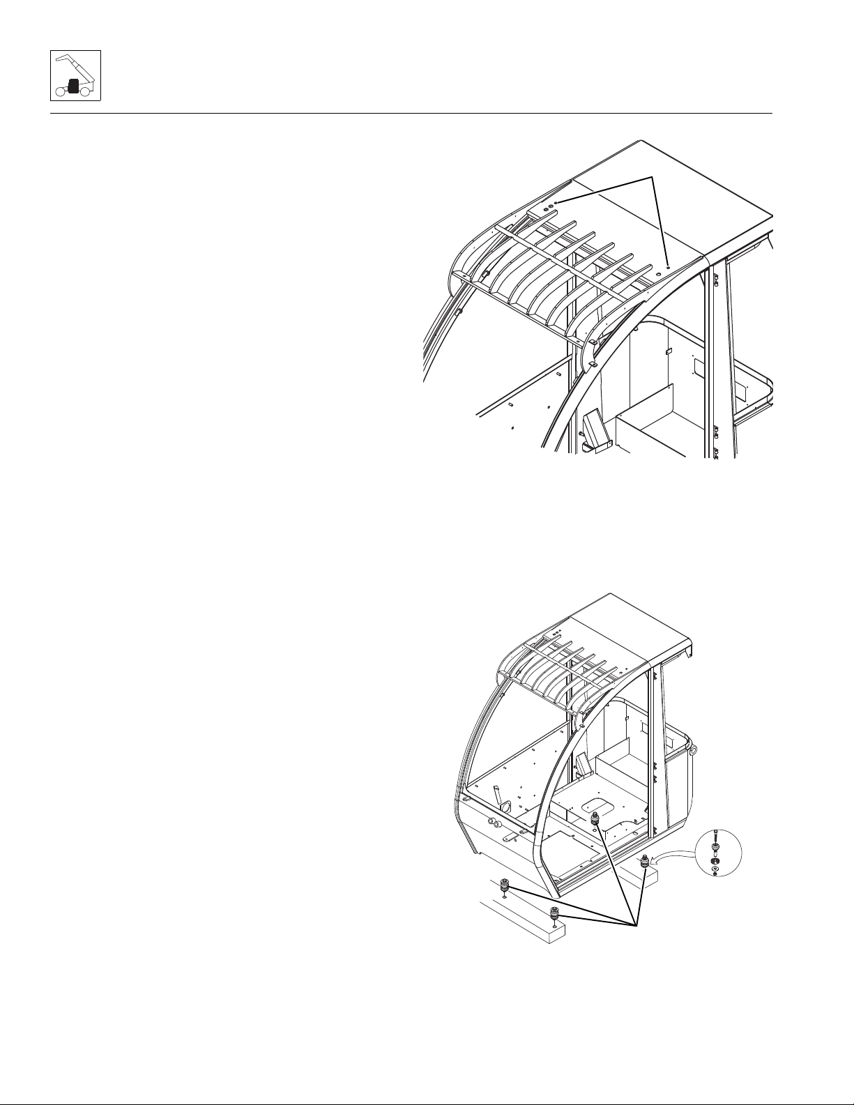
Cab and Covers
MZ0660
1
MZ0640
2
4. Properly disconnect the battery.
5. Remove the belly pan.
6. Drain the engine radiator. Refer to Section 7.4.3,
“Radiator/Oil Cooler and Coolant Heater
Replacement.”
7. Working under the cab, remove the cab bottom
shield.
8. Label, disconnect and cap the heater hoses.
9. Remove the lens-head screws in the cab and
remove the console panel below the right side
window to access the wire harness connections, the
right rear side panel and the left rear cup holder
panel to access the two rear cab mount bolts. Also
remove the rubber floor mat to access the front two
cab mount bolts.
10. Disconnect the cab-to-wiring harness connectors at
the circuit board. Push the harness connect or s
through the opening at the right front corner of the
cab.
11. 8, 9, 12 & 13M machines: Remove the park brake
cover. Disconnect the park brake switch connector
and park brake cable.
17M machines: Remove the park brake cover.
Label, disconnect and cap the hydraulic hoses
attached to the park brake lever. Cap all fittings to
keep dirt and debris from entering the hydraulic
system. Disconnect the park brake switch.
12. Working under the cab, label, disconnect and cap
the hydraulic hoses at the cab fittings. Plug the
hoses and cap the fittings.
13. Disconnect the throttle cable from the throttle pedal
lever. Push the throttle cable through the bottom of
the cab.
14. Install two lifting eye bolts with a suitable lifting
capacity in the existing threaded holes (1) at the top
corners of the windshield.
15. Secure the cab with a hoist or overhead crane and
sling. Do not lift the cab at this time.
4-10
16. Remove the four cab-to-frame bolts (2), flat washers
and nuts.
3508PS, 3509PS, 3512PS, 3513PS, 4008PS, 4009PS, 4012PS, 4013PS, 4017PS, 40.8, 40.9

Cab and Covers
17. Remove the mirrors and all other cab components
as needed, if not previously removed.
18. Use a hoist or overhead crane and sling attached to
the cab, carefully begin to lift the cab. Stop and
check that all wiring, hydraulic hoses and fasteners
are disconnected or removed.
19. When all wiring, hydraulic hoses and fasteners are
disconnected or removed, carefully and slowly lift
the cab and remove it from the frame.
20. When the cab is completely clear of the machine,
carefully lower it to the ground. Block up or support
the cab so that it does not move or fall over. Assure
that no personnel enter the cab while it is being
removed from the machine.
21. Inspect the condition of the fittings, clamps,
hydraulic hoses, etc. Replace parts as indicated by
their condition.
22. Inspect and replace other machine parts that are
exposed with the cab removed. Repair or replace as
required.
4.5 CAB INSTALLATION
1. Block all four wheels to help prevent the machine
from moving. Assure that there is sufficient overhead
and side clearance for cab installation.
2. Attach a sling with suitable lifting capacity through
the previously installed eye bolts on top of the cab.
3. Using a hoist or overhead crane and sling attached
to the two lifting eyes, carefully begin to align the cab
with the mounting holes in the frame. Stop and
check that wiring, hydraulic hoses, cables, etc., will
not be pinched or damaged as the cab is positioned.
Readjust the position of the sling as needed to help
balance the cab during installation.
4. Install the four bolts through the cab/frame mounts
and install the four washers and nuts. Remove the
sling and both lifting eye bolts. Tighten and torque
the four mounting bolts to 150 Nm (110 lb-ft).
5. Uncap and connect the previously labeled heater
hoses to the heater assembly.
6. Uncap and connect the previously labeled air
conditioner lines (if equipped) to the heater
assembly.
7. 8, 9, 12, & 13M machines: Route the park brake
cable back in to th e cab. S ecur e the pa rk br ake c able
to the park brake lever with the pre-existing pin.
Connect the previously labele d elec tric al connec tor
to the park brake lever.
17M machines: Route the park brake hydraulic
hoses back into the cab. Uncap and connect the
previously labeled hydraulic hoses to their
appropriate locations. Connect the previously
labeled electrical connector to the park brake lever.
8. Connect the throttle cable to the throttle pedal lever.
Adjust the throttle as required.
9. Route any hydraulic hoses through the opening at
the right front corner of the cab.
10. Uncap and connect the previously labeled hydraulic
hoses to their appropriate locations.
11. Connect the previously labeled windshield wiper
fluid lines to the appropriate locations.
12. Route the wiring harness connectors through the
opening at the right front corner of the cab and up
into the side console.
13. Connect the previously labeled cab-to-wiring
harness connectors.
14. Install the right side console panel, the right rear side
panel, the left rear cup holder panel and the rubber
floor mat.
15. Fill the cooling system completely with coolant,
allowing time for the coolant to fill the engine block.
The cooling system capacity is listed in Section 2.4,
“Fluids, Lubricants and Capacities.”
16. Properly connect the battery.
17. Start the engine and check the operation of all
controls. Check for hydraulic leaks. Check the
hydraulic oil level in the tank and add oil as required.
Note: When the engine is initially started, run it briefly at
low idle and check the machine for any visual sign of
fluid leakage. STOP the engine immediately if any
leakage is noted, and make any necessary repairs
before continuing.
18. Wait for the engine to cool and check the coolant
level. Add coolant to the overflow bottle as required
to bring the coolant to the proper level.
19. Reinstall engine belly pan.
20. Reinstall the cab bottom shield.
21. Close and secure the engine cover.
22. Unblock the wheels.
23. Remove the Do Not Operate Tags from both the
ignition key switch and the steering wheel.
3508PS, 3509PS, 3512PS, 3513PS, 4008PS, 4009PS, 4012PS, 4013PS, 4017PS, 40.8, 40.9
4-11

Cab and Covers
This Page Intentionally Left Blank
4-12
3508PS, 3509PS, 3512PS, 3513PS, 4008PS, 4009PS, 4012PS, 4013PS, 4017PS, 40.8, 40.9

Section 5
Axles, Drive Shafts, Wheels and Tires
Contents
PARAGRAPH TITLE PAGE
5.1 Axle, Drive Shaft and Wheel Component Terminology. . . . . . . . . . . . . . . . . . . . 5-2
5.2 General Information . . . . . . . . . . . . . . . . . . . . . . . . . . . . . . . . . . . . . . . . . . . . . . . . 5-3
5.3 Axle Assemblies . . . . . . . . . . . . . . . . . . . . . . . . . . . . . . . . . . . . . . . . . . . . . . . . . . . 5-3
5.3.1 Axle Serial Number Plate . . . . . . . . . . . . . . . . . . . . . . . . . . . . . . . . . . . . . 5-3
5.3.2 Axle Specifications . . . . . . . . . . . . . . . . . . . . . . . . . . . . . . . . . . . . . . . . . . 5-3
5.3.3 Axle Internal Service. . . . . . . . . . . . . . . . . . . . . . . . . . . . . . . . . . . . . . . . . 5-3
5.3.4 Axle Maintenance. . . . . . . . . . . . . . . . . . . . . . . . . . . . . . . . . . . . . . . . . . . 5-3
5.3.5 Axle Removal . . . . . . . . . . . . . . . . . . . . . . . . . . . . . . . . . . . . . . . . . . . . . . 5-4
5.3.6 Axle Installation . . . . . . . . . . . . . . . . . . . . . . . . . . . . . . . . . . . . . . . . . . . . 5-4
5.3.7 Axle Assembly and Drive Shaft T roubleshooting . . . . . . . . . . . . . . . . . . . 5-6
5.4 Drive Shafts. . . . . . . . . . . . . . . . . . . . . . . . . . . . . . . . . . . . . . . . . . . . . . . . . . . . . . . 5-9
5.4.1 Drive Shaft Inspection and Service . . . . . . . . . . . . . . . . . . . . . . . . . . . . . 5-9
5.4.2 Drive Shaft Maintenance . . . . . . . . . . . . . . . . . . . . . . . . . . . . . . . . . . . . . 5-9
5.4.3 Drive Shaft Removal. . . . . . . . . . . . . . . . . . . . . . . . . . . . . . . . . . . . . . . . . 5-9
5.4.4 Drive Shaft Cleaning and Drying . . . . . . . . . . . . . . . . . . . . . . . . . . . . . . . 5-9
5.4.5 Drive Shaft Installation . . . . . . . . . . . . . . . . . . . . . . . . . . . . . . . . . . . . . . . 5-9
5.5 Wheels and Tires . . . . . . . . . . . . . . . . . . . . . . . . . . . . . . . . . . . . . . . . . . . . . . . . . . 5-10
5.5.1 Removing Wheel and Tire Assembly from Machine. . . . . . . . . . . . . . . . . 5-10
5.5.2 Installing Wheel and Tire Assembly onto Machine. . . . . . . . . . . . . . . . . . 5-11
5.6 Brakes . . . . . . . . . . . . . . . . . . . . . . . . . . . . . . . . . . . . . . . . . . . . . . . . . . . . . . . . . . . 5-11
5.6.1 Brake Disk Inspection. . . . . . . . . . . . . . . . . . . . . . . . . . . . . . . . . . . . . . . . 5-11
5.7 Towing A Disabled Machine . . . . . . . . . . . . . . . . . . . . . . . . . . . . . . . . . . . . . . . . . 5-12
5.7.1 Towing (8, 9, 12 & 13M) . . . . . . . . . . . . . . . . . . . . . . . . . . . . . . . . . . . . . . 5-12
5.7.2 Manually Releasing the Park Brake (17M). . . . . . . . . . . . . . . . . . . . . . . . 5-12
5.7.3 Manually Resetting the Park Brake (17M) . . . . . . . . . . . . . . . . . . . . . . . . 5-12
3508PS, 3509PS, 3512PS, 3513PS, 4008PS, 4009PS, 4012PS, 4013PS, 4017PS, 40.8, 40.9
5-1
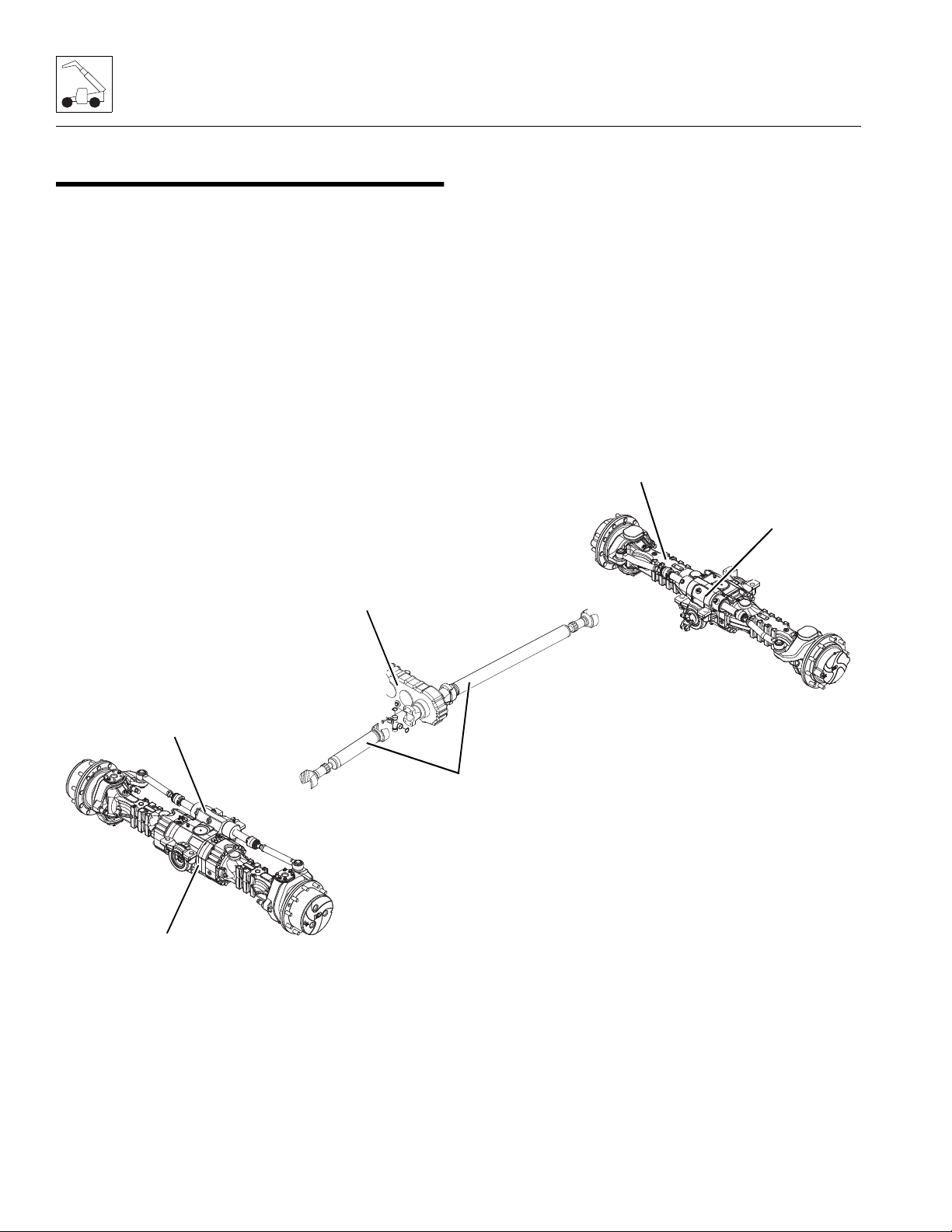
Axles, Drive Shafts, Wheels and Tires
MZ1510
REAR AXLE
ASSEMBLY
STEERING
CYLINDER
(FRONT)
FRONT
AXLE
ASSEMBLY
STEERING
CYLINDER
(REAR)
DRIVE SHAFTS
TRANSMISSION
DROP BOX
5.1 AXLE, DRIVE SHAFT AND WHEEL COMPONENT TERMINOLOGY
To understand the safety, operation and maintenance
information presented in this section, it is necessary that
the operator/mechanic be familiar with the names and
locations of the major assemblies of the axles, drive shafts,
wheels and tires. The following illustration identifies the
components that are referred to throughout this section.
5-2
3508PS, 3509PS, 3512PS, 3513PS, 4008PS, 4009PS, 4012PS, 4013PS, 4017PS, 40.8, 40.9

Axles, Drive Shafts, Wheels and Tires
5.2 GENERAL INFORMATION
Note: To help ensure optimum performance, the drive
shaft assemblies are specially balanced as a unit at the
factory. When servicing any flange yoke, slip yoke or
drive shaft tube, order a complete assembly if
components are bent of damaged. Refer to the
appropriate parts manual for ordering information.
Before performing any inspection, maintenance or
service operation, thoroughly clean the unit. The axles
and drive shafts should be checked and repaired only by
experienced service technicians who are aware of all
safety instructions and particular component features.
Use suitable products to thoroughly clean all
disassembled mechanical parts to help prevent personal
injury to the worker and prevent damage to the parts.
Carefully inspect the integrity of all moving parts
(bearings, yokes, tubes, gears, shafts, etc.) and fasteners
(nuts, bolts, washers, etc.) as they are subject to major
stress and wear. Always replace elastic locknuts and any
damaged, worn, cracked, seiz ed or otherw is e improp er
parts that could affect the safe and proper functioning of
the machine, axles and drive shafts.
5.3 AXLE ASSEMBLIES
5.3.1 Axle Serial Number Plate
The front and rear axle serial number plate is located on
a mounting pad on the front side of the center section of
each axle. Information on the serial number plate is
required in correspondence regarding the axle.
Supply information from the axle serial number plate
when communicating about an axle assembly or axle
components.
5.3.2 Axle Specifications
General axle specifications are found in Section 2.4,
“Fluids, Lubricants and Capacities.”
5.3.3 Axle Internal Service
Detailed axle service instructions (covering the axle,
differential, brakes and wheel-end safety, repair,
disassembly, reassembly, adjustment and
troubleshooting information) are provided in the Dana
Spicer Maintenance and Repair Manual (P/N 31200162).
WARNING
DO NOT service the machine without following all
safety precautions as outlined in Section 1, “Safety
Practices,” of this manual.
5.3.4 Axle Maintenance
CLEANING: Clean parts with machined or ground
surfaces (such as gears, bearings and shafts) with
emulsion cleaners or petroleum-based cleaners. DO
NOT steam clean internal components and the interior of
the planetary hub and axle housing. Water can cause
corrosion of critical parts. Rust contamination in the
lubricant ca n cause gear and bearing failure. Remove
old gasket material from all surfaces.
DRYING: Use clean, lintless towels to dry components
after cleaning. DO NOT dry bearings by spinning them
with compressed air; this can damage mating surfaces
due to lack of lubrication. After drying, lightly coat
components with oil or a rust-preventive chemical to help
protect them from corrosion. If sto rin g co mp on ents f or a
prolonged period, wrap them in wax paper.
PERIODIC OPERATION REQUIREMENT: Every two
weeks, drive the machine far enough to cause the drivetrain components to make several complete revolutions.
This will help ensure that internal components receive
lubrication to minimize deterioration caused by
environmental factors such as high humidity.
SUBMERSION: If the machine has been exposed to
water deep enough to cover the hubs, disassemble the
wheel ends and inspect for water damage and
contamination. If the carrier housing was submerged in
water, especially if the water level was above the vent
tube (breather), drain the axle and inspect internal parts
for water damage and contamination. Before assembling
and refilling the unit with the specified lubricant(s), clean,
examine and replace damaged parts as necess ar y.
Note: Use a suitable puller for bearing removal. Clean,
inspect and lubricate all bearings just prior to
reassembly. If replacement of a damaged bearing cup or
cone is necessary, replace the cup and cone as a set.
3508PS, 3509PS, 3512PS, 3513PS, 4008PS, 4009PS, 4012PS, 4013PS, 4017PS, 40.8, 40.9
5-3

Axles, Drive Shafts, Wheels and Tires
MZ1030
1
MZ1520
2
5.3.5 Axle Removal
The front and rear axle assemblies differ in that the front
axle assembly is equipped with a parking brake
mechanism and a limited-slip feature; the rear axle has
neither. The follo wing steps outline a typical a xle remov al
procedure, suitable for either the front or the rear axle
assembly.
Cleanliness is extremely important. Before attempting to
remove the axle, thoroughly clean the machi ne . Avoi d
spraying water or cleaning solution on the outrigger
solenoids and other electrical components. If using a
steam cleaner, seal all openings before steam cleaning.
Note: Clear the work area of all debris, unnecessary
personnel, etc. Allow sufficient space to raise the
machine and to remove the axle.
1. Park the machine on a firm, level surface, level the
machine, fully retract the boom, lower the boom,
place the transmission control lever in
(N) NEUTRAL, engage the park brake and shut the
engine OFF.
2. Place a Do Not Operate Tag on both the ignition key
switch and steering wheel, stating that the machine
should not be operated.
3. Open the engine cover. Allow the system fluids to
cool.
4. Properly disconnect the battery.
5. Remove the fender assemblies.
allow the axle oil to drain into the receptacle.
Transfer the used axle oil into a suitable covered
container, and label the container as "Used Oil".
Dispose of used oil at an approved recycling facility.
7. Label, disconnect and cap the steering and brake
lines at the axle. Wipe up any spilled oil.
8. Block the front and rear of both tires on the axle that
is not being removed. Ensure that the machine wil l
remain in place during axle removal before
proceeding.
9. Raise the machine using a suitable jack or hoist.
Place suitable supports under both sides of the
frame and lower the machine onto the supports.
Ensure that the machine will remain in place during
axle removal.
10. Support the axle that is being removed with a suitable
jack, hoist or overhead crane and sling. DO NOT
raise the axle or the machine.
11. Mark and remove both wheel and tire assemblies
from the axle that is being removed. Refer to Section
5.5.1, “Removing Wheel and Tire Assembly from
Machine.”
12. Remove the drive shaft assembly. Refer to Section
5.4.3, “Drive Shaft Removal.”
13. On the front axle, remove the hardware securing the
frame level cylinder or bar. Tap the mount pin out,
and move the cylinder or bar to prevent it from
interfering with axle removal.
14. Remove the park brake cable from the front axle (8,
9, 12 & 13M only).
15. Remove the bolts and locknuts securing the axle to
the frame.
16. Remove the axles from the machine using the jack,
hoist or overhead crane and sling supporting the
axle. DO NOT raise or otherwise disturb the
machine while removing the axl e. Bal an ce the axle
and prevent it from tipping, turning or falling while
removing it from beneath the machine. Place the
axle on a suitable support or holding stand.
6. If the axle will be disassembled after removal, place
a suitable receptacle under the axle (1) and wheel
hubs drain plugs (2). Remove the drain plugs and
5-4
3508PS, 3509PS, 3512PS, 3513PS, 4008PS, 4009PS, 4012PS, 4013PS, 4017PS, 40.8, 40.9
5.3.6 Axle Installation
The front and rear axle assemblies differ in that the front
axle assembly is equipped with a parking brake
mechanism and limited-slip feature; the rear axle has
neither. The steps below outline a typical axle installation
procedure, suitabl e for eit her the fr ont or the rear ax le
assembly.
1. Before proceeding, ensure that the machine will
remain in place during axle installation. Block the

Axles, Drive Shafts, Wheels and Tires
MZ1030
4
3
MZ5820
5
front and rear of both tires on the axle that is already
installed on the machine.
2. If applicable, raise the machine using a suitable jack
or hoist. Place suitable supports beneath the frame
and lower the machine onto the supports, allowing
enough room for axle installation. Ensure that the
machine will remain in place during axle installation.
3. Using a suitable jack, hoist or overhead crane and
sling, remove the axle from its support or holding
stand. Balance the axle and prevent it from tipping,
turning or falling while positioning it beneath the
machine. DO NOT raise or otherwise disturb the
machine while installing the axle. Keep the axle
supported and balanced on the jack, hoist or
overhead crane and sling throughout the installation
procedure.
4. Position the axle under the frame, and align the axle
housing with the holes in the frame.
5. Install the axle bolts and nuts. Tighten and torque
the axle nuts to 550-600 Nm (406-443 lb-ft).
6. Move the cylinder or bar into position on the front
axle anchor ( if necessary). Install the mount pin.
7. Apply a multi-purpose grease through the selftapping lube fitting to lubricate the self-align bearing
and the cylinder-mount pin (if required).
8. Install the drive shaft assemblies. Refer to Section
5.4.5, “Drive Shaft Installation.”
9. If reinstalling an axle previously removed from the
machine, position the driveshaft yoke on the axle
according to the alignment marks made earlier. If
installing a new axle, note the position of the
driveshaft yoke at the transmission. Align the
driveshaf t yo ke o n t he axle in the same pl a ne as th e
yoke on the transmission.
10. Tighten the axle oil drain plug, loosen and remove
the axle oil fill plug (3). Fill the axle through the axle
fill plug until the oil level is even with the oil check
level plugs (4). Refe r to Section 2.4, “Fluids,
Lubricants and Capacities,” for proper oil and
capacities.
11. Rotate wheel hubs 90 degrees so the drain plug (5)
becomes the fill plug. Refer to Section 2.4, “Fluids,
Lubricants and Capacities,” for proper oil and
capacities.
12. Install the wheel and tire assemblies. Refer to
Section 5.5.2, “Installing Wheel and Tire Assembly
onto Machine.”
13. Carefully remove the jack, hoist or overhead crane
and sling supporting the axle.
14. Carefully raise the machine using a suitable jack or
hoist. Remove the supports from beneath the frame
and lower the machine to the ground.
Note: ALWAYS use new o-rings when servicing the
machine.
15. Install new o-rings into the fittings. Lubricate the
o-rings with clean hydraulic oil.
16. Uncap and connect the steering and brake lines at
their axle fittings.
17. Install the park brake on the front axle (8, 9, 12 &
13M only).
18. If reinstalling the front axle, the hydraulic brake
circuit will need to be bled. Refer to Section 8.9.3,
“Brake Test.”
19. Check the hydraulic reservoir oil level.
20. Install the fender assemblies.
21. Properly connect the battery.
22. Unblock the wheels.
23. Start the engine. Turn the steering wheel several
times lock to lock, operate the frame tilt funct ion
several times in both directions and check the
function of the brakes. Check for hydraulic leaks,
and tighten or repair as necessary.
24. Close and secure the engine cover.
25. Remove the Do Not Operate Tags from both the
ignition key switch and the steering wheel.
3508PS, 3509PS, 3512PS, 3513PS, 4008PS, 4009PS, 4012PS, 4013PS, 4017PS, 40.8, 40.9
5-5

Axles, Drive Shafts, Wheels and Tires
5.3.7 Axle Assembly and Drive Shaft Troubleshooting
Problem Cause Remedy
1. Excessive axle noise while
driving.
1. Oil level too low. 1. Fill oil to correct level. Refer to
Section 2.4, “Fluids, Lubricants
and Capacities.”
2. Axle and/or wheel end housings
filled with incorrect oil or oil level
low.
2. Drain axle and/or wheel end
housings and fill to correct level
®
with Mobilfluid 424
ISO 46.
Refer to Section 2.4, “Fluids,
Lubricants and Capacities.”
3. Incorrect alignment of ring and
pinion gears.
4. Incorrect pinion (input) shaft
bearing preload.
3. Correct alignment by adding or
removing shims as needed.
4. Correct bearing preload by
adding or removing shims as
needed.
5. Worn or damaged bearings. 5. Replace bearings as needed.
6. Worn or broken gear teeth. 6. Replace gears as needed.
7. Contamination in the axle. 7. Drain axle and/or wheel end
housings and fill to correct level
®
with Mobilfluid 424
ISO 46.
Refer to Section 2.4, “Fluids,
Lubricants and Capacities.”
2. Intermittent noise when
traveling.
3. Vibration or intermittent noise
when traveling.
8. Axle housing damaged. 8. Replace damaged parts.
1. Universal joint(s) worn or
damaged.
2. Differential ring and/or pinion
gears damaged.
1. Drive shaft universal joint
assembly(ies) incorrectly
1. Repair or replace universal
joints as needed.
2. Determine cause and repair as
needed.
1. Tighten capscrews to correct
torque.
tightened.
2. Drive shaft universal joint(s)
worn or damaged.
3. Drive shaft(s) damaged/
unbalanced.
2. Repair or replace universal
joints as needed.
3. Replace drive shaft(s) as
needed.
5-6
3508PS, 3509PS, 3512PS, 3513PS, 4008PS, 4009PS, 4012PS, 4013PS, 4017PS, 40.8, 40.9

Axles, Drive Shafts, Wheels and Tires
Problem Cause Remedy
4. Oil leaking from axle
(differential housing and/or
axle housings).
1. Drain and/or inspection plugs
loose and/or o-rings damaged
or missing.
2. Hose fittings loose. 2. Tighten fittings.
3. Axle shaft seal damaged or
missing and/or worn or
damaged shaft sealing
surfaces.
4. Input shaft multi-seal ring
damaged or missing and/or
worn or damaged pinion (input)
shaft sealing surface s.
5. Axle casing to brake housing
and/or brake housing to
differential assembly o-rings
and/or seals worn or damaged.
6. Axle housing mounting nuts and
capscrews loose.
7. Differential and/or axle
housing(s) damaged.
1. Replace o-rings as needed and
tighten plugs to 130 Nm
(96 lb-ft).
3. Replace seal and/or joint
coupling fork shaft (axle shaft).
4. Replace multi-seal ring and/or
input shaft. Adjust ring and
pinion alignment and bearing
preload as described in the
Dana Repair Manuals.
5. Replace o-rings and seals.
6. Tighten housing nuts and
capscrews to 390 Nm
(288 lb-ft).
7. Replace housing(s) as needed.
5. Oil leaking from wheel end
housing (planet carrier).
6. Oil leaking from steering
cylinder.
1. Oil level plugs loose and/or
o-rings damaged or missing.
2. O-ring between hub and
housing (planet carrier)
damaged or missing.
3. Shaft seal damaged or missing
and/or worn or damaged shaft
sealing surfaces.
4. Housing capscrews loose. 4. Tighten housing capscrews to
5. Housing (planet carrier) damaged. 5. Replace housing (planet carrier).
1. Hose fittings loose. 1. Tighten fittings.
2. Steering cylinder o-rings and/or
seals worn or damaged.
3. Piston rod seal worn or
damaged.
4. Cylinder tube damaged. 4. Replace cylinder tube.
1. Replace o-rings as needed and
tighten plugs to 130 Nm
(96 lb-ft).
2. Replace o-ring.
3. Replace seal and/or fork joint
shaft.
55 Nm (41 lb-ft).
2. Replace o-rings and seals.
3. Replace piston rod seal.
3508PS, 3509PS, 3512PS, 3513PS, 4008PS, 4009PS, 4012PS, 4013PS, 4017PS, 40.8, 40.9
5-7

Axles, Drive Shafts, Wheels and Tires
Problem Cause Remedy
7. Axle overheating. 1. Oil level too high. 1. Fill oil to correct level with
Mobilfluid 42 4
®
ISO 46. Refer to
Section 2.4, “Fluids, Lubricants
and Capacities.”
2. Axle and/or wheel end housings
filled with incorrect oil or oil
contaminated or oil level low.
2. Drain axle and fill to correct level
®
with Mobilfluid 424
ISO 46.
Refer toSection 2.4, “Fluids,
Lubricants and Capacities.”
3. Dragging park brake. 3. Adjust park brake cable as
needed.
8. High steering effort required. 1. Steering (hydraulic) system not
operating properly.
2. Excessive joint housing swivel
bearing preload.
1. Refer to Section 8.10.8,
“Steering Cylinders.”
2. Correct bearing preload by
adding or removing shims as
needed.
3. Worn or damaged swivel
bearings.
9. Slow steering respo nse. 1. Steering (hydraulic) system not
operating properly.
2. Steering cylinder leaking
internally.
3. Replace swivel bearings as
needed.
1. Refer to Section 8.10.8,
“Steering Cylinders.”
2. Repair or replace steering
cylinder as needed.
10. Excessive noise when brakes
1. Brake discs worn. 1. Check brake discs for wear.
are engaged.
2. Brake discs damaged. 2. Replace brake discs.
11. Brakes will not engage. 1. Brake (hydraulic) system not
operating properly.
2. Brake piston o-rings and seals
damaged (leaking).
12. Brakes will not hold the
1. Brake discs worn. 1. Check brake discs for wear.
machine or braking power
reduced.
2. Brake (hydraulic) system not
operating properly.
3. Brake piston o-rings and seals
damaged (leaking).
Refer to Section 5.6, “Brakes.”
1. Refer to Section 8.10.8,
“Steering Cylinders.”
2. Replace o-rings and seals.
Refer to Section 5.6, “Brakes.”
2. Refer to Section 8.9.3, “Brake
Test.”
3. Replace o-rings and seals.
5-8
3508PS, 3509PS, 3512PS, 3513PS, 4008PS, 4009PS, 4012PS, 4013PS, 4017PS, 40.8, 40.9
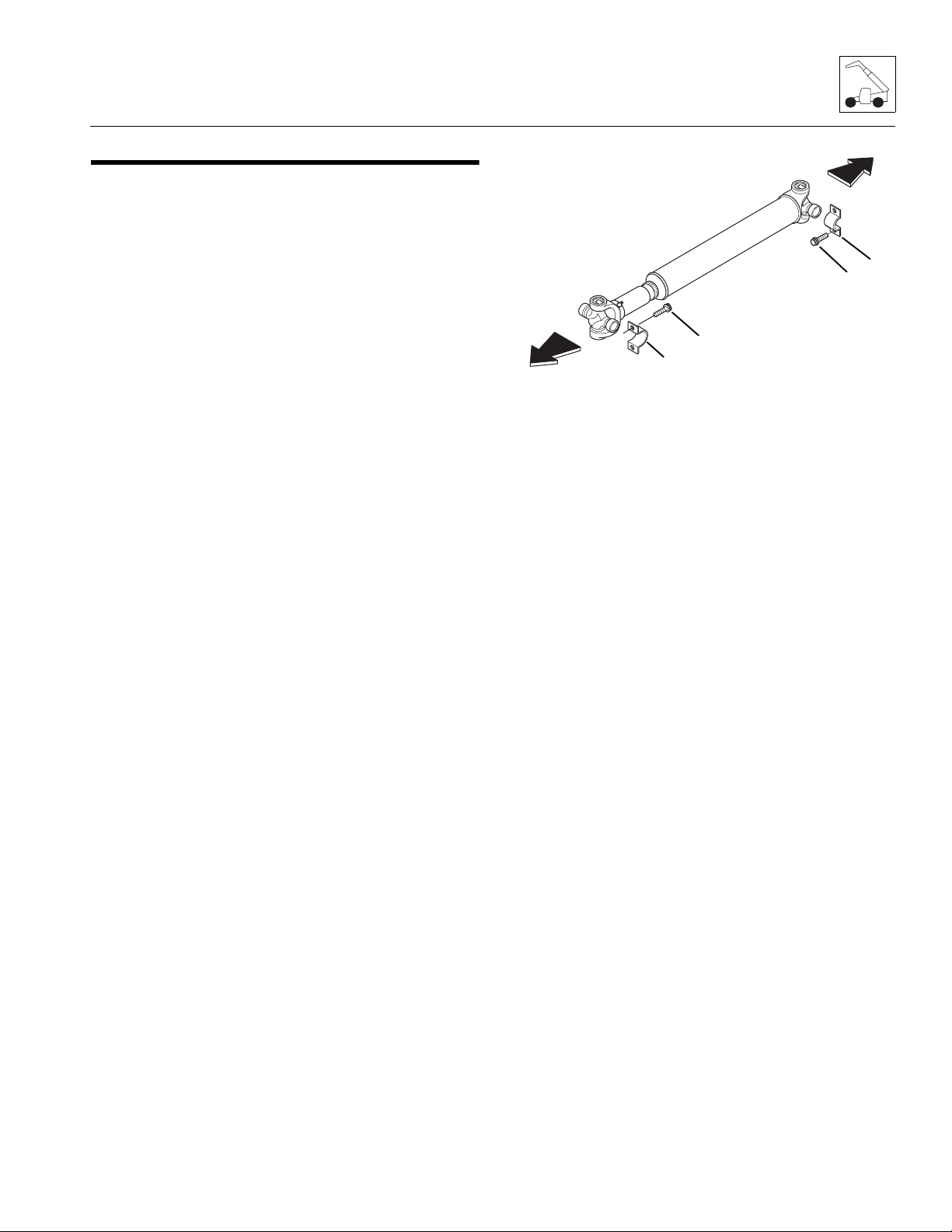
5.4 DRIVE SHAFTS
To Transmission
To Axle
1
2
3
4
5.4.1 Drive Shaft Inspection and Service
Whenever servicing the machine, conduct a visual
inspection of the drive shaft and cross and bearing
assembly (universal joints, or U-joints). A few moments
spent doing this can help prevent further problems and
down time lat er .
Inspect area where the drive shaft flange yoke and slip
yoke mount to the drive shaft. Attempt to turn drive shaft
in both directions. Look for excessive looseness, missing
parts, cracks or other damage. Worn or damaged drive
shaft and cross and bearing assembly may cause an
excessive amount of vibration or noise.
Note: Any bolt removed from the drive shaft assembly
MUST be replaced. Do Not re-torque.
5.4.2 Drive Shaft Maintenance
Refer to Section 2.6, “Lubrication Schedules,” for
information regarding the lubrication of the grease fittings
on the drive shafts.
5.4.3 Drive Shaft Removal
1. Park the machine on a firm, level surface, level the
machine, fully retract the boom, lower the boom,
place the transmission control lever in
(N) NEUTRAL, engage the park brake and shut the
engine OFF.
2. Place a Do Not Operate T ag on both the ignition key
switch and steering wheel, stating that the machine
should not be operated.
3. Open the engine cover. Allow the engine to cool.
4. Properly disconnect the battery.
5. Block the wheels.
6. The drive shaft assembly is a balanced assembly.
Mark the yoke and axle, transmission and the shaft
and slip yoke so that these components can be
returned to their original positions when reinstalled.
Yokes at both ends of the drive shaft must be in the
same plane to help prevent excessive vibration.
Axles, Drive Shafts, Wheels and Tires
7. Remove the four capscrews (1) and two straps (2)
securing the bearing cross to the transmission
output shaft flange. Discard capscrews.
8. Remove the fo ur ca pscr ews (3) and two straps (4)
securing the bearing crosse s to the ax le . Discard
capscrews.
9. Remove the front drive shaft assembly.
10. Repeat the above procedure for the rear drive shaft.
5.4.4 Drive Shaft Cleaning and Drying
1. Disassemble and clean all parts using an approved
cleaning fluid. Allow to dry.
2. Remove any burrs or rough spots from all machined
surfaces. Re-clean and dry as required.
5.4.5 Drive Shaft Installation
Note: The yoke at both ends of the drive shaft must be
in the same plane to help prevent excessive vibration.
1. Raise the drive shaft assembly into position. The
slip-yoke end of the drive shaft mounts toward the
axle. If reinstalling a drive shaft previously removed,
align the flange yokes according to the alignment
marks made during removal.
2. Install the four capscrews and two straps securing
the bearing crosses to the transmission. Torque the
capscrews to 38 Nm (28 lb-ft).
3. Install the four capscrews and two straps securing
the bearing crosses to the axle. Torque the
capscrews to 38 Nm (28 lb-ft).
4. Repeat the above procedure on the rear drive shaft.
5. Properly connect the battery.
6. Unblock the wheels.
7. Close and secure the engine cover.
8. Remove the Do Not Operate Tags from both the
ignition key switch and the steering wheel.
3508PS, 3509PS, 3512PS, 3513PS, 4008PS, 4009PS, 4012PS, 4013PS, 4017PS, 40.8, 40.9
5-9

Axles, Drive Shafts, Wheels and Tires
MY4190
5
5.5 WHEELS AND T IRES
WARNING
Mismatched tire sizes, ply ratings or mixing of tire
types (radial tires with bias-ply tires) may compromise
machine stability and may cause machine to tip over.
JLG recommends a replacement tire to be the same size,
ply and brand as originally installed. Refer to the
appropriate parts manual for ordering information. If not
using a JLG approved replacement tire, JLG
recommends that replacemen t tire s have the foll owi ng
characteristics:
• Equal or greater ply/load rating and size of original.
• Tire tread contact width equal or greater than
original.
• Wheel diameter, width and offset dimensions equal
to the original.
• Approved for the application by the tire manufacturer
(including inflation pressure and maximum tire load).
The rims installed have been designed for stability
requirements which consist of track width, tire pressure
and load capacity. Size changes such as rim width,
center piece location, larger or smaller diameter, etc.,
without written factory recommendations, may result in
unsafe condition regarding stability.
The tires are filled with air only when the machine leaves
the factory. JLG does not recommend the use of hydrofill
as a tire-fill substance because of possible environmental
impact.
Large-bore valve stems are used to help expedite tire
inflation and deflation. An inner tube may be used if a tire
does not provide an airtight seal. Check tire inflation
pressures when the tires are cold. When mounting a tire
on the wheel, the tire must be mounted on the wheel
respective of the directional tread pattern of the tire; this
produces a left or right tire and wheel assembly.
The wheel and tire assemblies must be installed with the
directional tread pattern “arrows” (5) facing in the
direction of forward trave l.
5.5.1 Removing Wheel and Tire Assembly from Machine
1. Park the machine on a firm, level surface, level the
machine, fully retract the boom, lower the boom,
place the transmission control lever in
(N) NEUTRAL, engage the park brake and shut the
engine OFF.
2. Place a Do Not Operate Tag on both the ignition key
switch and steering wheel, stating that the machine
should not be operated.
3. Loosen, but DO NOT remove the lug nuts on the
wheel and tire assembly to be removed.
4. Place a suitable jack under the axle pad closest to
the wheel being removed. Raise the machine and
position a suitable support beneath the axle. Allow
sufficient room to lower the machine onto the
support and to remove the wheel and tire assembly.
5. Lower the machine onto the support.
6. Remove lug nuts and lug washers in an alternating
pattern.
7. Remove the wheel and tire assembly from the
machine.
5-10
3508PS, 3509PS, 3512PS, 3513PS, 4008PS, 4009PS, 4012PS, 4013PS, 4017PS, 40.8, 40.9

Axles, Drive Shafts, Wheels and Tires
Mh3300
Tread "arrows" must point
forward
Install tires onto wheels to
rotate in proper direction
MY4200
1
3
8
6
9
4
10
5
2
7
MZ1030
6
8
MZ5830
7
5.5.2 Installing Wheel and Tire Assembly onto Machine
Note: The wheel and tire assemblies must be installed
with the directional tread pattern “arrows” facing in the
direction of forward travel.
5.6 BRAKES
5.6.1 Brake Disk Inspection.
a. Front and Rear Axles
1. Block all four wheels to help prevent the machine
from moving after the parking brake is disabled.
2. Remove the oil-level plug (6) on each side of the
axle.
3. Have an assistant sit in the cab and apply the
brakes, keeping pressure applied.
3508PS, 3509PS, 3512PS, 3513PS, 4008PS, 4009PS, 4012PS, 4013PS, 4017PS, 40.8, 40.9
1. Position wheel onto studs on wheel end of axle.
2. Install wheel lug washers.
3. Start all nuts by hand to prevent cross threading. DO
NOT use a lubricant on threads or nuts.
4. Tighten lug nuts in an alternating pattern as
indicated in figure. Torque to 575 Nm (424 lb-ft).
5. Remove machine from supports.
6. Remove the Do Not Operate Tags from both the
ignition key switch and the steering wheel.
4. Using a feeler gauge, check the gap between the
brake discs (7). If the gap is less than 4,5 mm
(0.18 in), replace the brake discs.
Note: If the brake discs are worn beyond their
tolerance, the brake disc must be replaced on both sides
of the axle at the same time.
5. Repeat steps 3 and 4 for the other side of the axle.
6. Fill the axle through the axle fill plug (8) until the oil
level is even with the oil check level plugs (6). Refer
to Section 2.4, “Fluids, Lubricants and Capacities,”
for proper oil and capacities.
5-11

Axles, Drive Shafts, Wheels and Tires
MZ1020
9
5.7 TOWING A DISABLED MACHINE
Towing a disabled machine should only be attempted as
a last resort, after exhausting all other options. Make
every effort to repair the machine, and move it under its
own power, before using the emergency towing
procedures outlined belo w.
On 17M machines, the park brake is hydraulically
operated. Therefore, the axle must have the park brake
manually be disabled. On 8, 9, 12 & 13M machines, the
park brake is cable operated and can be disabled in the
cab with the park brake lever.
5.7.1 Towing (8, 9, 12 & 13M)
1. Secure the machine to a suitable towing vehicle.
2. Release the park brake and set the transmission
control lever in (N) NEUTRAL.
3. Tow the machine to a suitable repair facility.
4. After towing is complete, engage the park brake.
5.7.2 Manually Releasing the Park Brake (17M)
Note: Block the wheels of the machine BEFORE
attempting to release the park brake. Once the park
brake is released the machine’s park brake AND service
brakes are inoperable.
Note: Turning the release bolts in to far could warp the
brake discs. DO NOT over tighten.
Note: After the machine has been towed to a secure
location, reactivate the park brake. Carefully follow the
procedures from start to finish. Consult your local JLG
distributor or the JLG Service Department if you are
unsure about any part of the procedure, or for specific
instructions concerning your particular situation.
5.7.3 Manually Resetting the Park Brake (17M)
Note: Block the wheels of the machine BEFORE
attempting to reset the machine’s park brake. Once the
park brake is reset the machine’s park brake AND
service brakes are operable.
1. Loosen the jam nuts on all four manual brake
release bolts.
2. Turn all four manual brake release bolts OUT a
quarter turn at a time to the dimension recorded
before starting the towing procedure.
3. Tighten the jam nuts on all four manual brake
release bolts.
After repairs to the machine have been made, start the
machine and check the park brake and service brakes for
proper function.
1. Measure the distance from the bolt head to the face
of the jam nut on all four of the manual brake release
bolts (9) located on each side of the front axle center
section (two per side). Record the measurements.
2. Loosen the jam nuts on the four manual brake
release bolts.
3. Turn all four release bolts in equally with a wrench or
socket BY HAND a quarter turn at a time up to
approximately 19 mm (0.750 in) or until resistance is
felt. Tighten the jam nuts.
5-12
3508PS, 3509PS, 3512PS, 3513PS, 4008PS, 4009PS, 4012PS, 4013PS, 4017PS, 40.8, 40.9

Section 6
Transmission:
Contents
PARAGRAPH TITLE PAGE
6.1 Transmission Assembly Component Terminology . . . . . . . . . . . . . . . . . . . . . . . 6-2
6.2 Transmission Description . . . . . . . . . . . . . . . . . . . . . . . . . . . . . . . . . . . . . . . . . . . 6-3
6.3 Transmission Serial Number . . . . . . . . . . . . . . . . . . . . . . . . . . . . . . . . . . . . . . . . . 6-3
6.4 Transmission Specifications . . . . . . . . . . . . . . . . . . . . . . . . . . . . . . . . . . . . . . . . . 6-3
6.4.1 Transmission Maintenance . . . . . . . . . . . . . . . . . . . . . . . . . . . . . . . . . . . . 6-3
6.4.2 Transmission Maintenance Schedule. . . . . . . . . . . . . . . . . . . . . . . . . . . . 6-3
6.5 Transmission Replacement . . . . . . . . . . . . . . . . . . . . . . . . . . . . . . . . . . . . . . . . . . 6-3
6.5.1 Transmission Removal . . . . . . . . . . . . . . . . . . . . . . . . . . . . . . . . . . . . . . . 6-4
6.5.2 Transmission Inspection and Internal Repair . . . . . . . . . . . . . . . . . . . . . . 6-5
6.5.3 Transmission Installation. . . . . . . . . . . . . . . . . . . . . . . . . . . . . . . . . . . . . . 6-5
6.5.4 After Transmission Service or Replacement. . . . . . . . . . . . . . . . . . . . . . . 6-6
6.6 Troubleshooting . . . . . . . . . . . . . . . . . . . . . . . . . . . . . . . . . . . . . . . . . . . . . . . . . . . 6-7
3508PS, 3509PS, 3512PS, 3513PS, 4008PS, 4009PS, 4012PS, 4013PS, 4017PS, 40.8, 40.9
6-1

Transmission:
MZ0670
OUTPUT SHAFT
(FRONT)
TORQUE CONVERTOR
DIPSTICK AND FILL TUBE
BREATHER
OUTPUT SHAFT
(REAR)
DROP BOX OIL LEVEL
SIGHT GAUGE
BREATHER
TRANSMISSION DROP BOX
FLEX PLATE ASSEMBLY
SHIFT SOLENOIDS
OIL FILTER
6.1 TRANSM I SSION ASSEMBLY COMPONENT TERMINOLOGY
To understand the safety, operation and maintenance
information presented in this section, it is necessary that
the operator/mechanic be familiar with the names and
locations of the major assemblies of the transmission.
The following illustration identifies the components that
are referred to throughout this section.
6-2
3508PS, 3509PS, 3512PS, 3513PS, 4008PS, 4009PS, 4012PS, 4013PS, 4017PS, 40.8, 40.9

WARNING
Transmission:
6.4.2 Transmission Maintenance Schedule
Complete transmission maintenance information is
located in the appropriate Operation & Safety Manual.
DO NOT service the machine without following all
safety precautions as outlined in Section 1, “Safety
Practices,” of this manual.
6.2 TRANSMISSION DESCRIPTION
Instructions in this section p erta in mai nly to ge ne ral
specifications, towing, m ainte nan ce i nf ormat ion , and
transmission removal and installation procedur es. For
internal transmission service instructi ons and detailed
specificat ions contact your local authorized service
distributor for a copy of the Dana Spicer Repair Manual
(P/N 31200163).
6.3 TRANSMISSION SERIAL NUMBER
The transmission serial number plate is located on the
front of the transmission case below the convertor
housing. Information specified on the serial number plate
includes the transmission model number, the
transmission serial numbe r and other data . Informati on
on the serial number plate is required in correspondence
regarding the transmission.
6.4 TRANSMISSION SPECIFICATIONS
6.4.1 Transmission Maintenance
Cleanliness is of ex trem e impo rtan ce. Be fo r e att emp tin g
any repairs, thoro ughly cl ean t he ext erio r of t he
transmission to help prevent dirt from entering while
performing maintenance checks and proce dures.
Section 2.5, “Maintenance Schedules.” provides a
suggested maintenance schedule with references to
pertinent procedures and instructions in this manual. To
help prevent transmission problems before they occur,
follow the maintenance schedule.
Note: Lubrication and Maintenance chart decals are
located inside the rear door of the machine or in the cab.
These decals contain a general maintenance schedule
that should be followed to maintain the machine in good
operating condition. Refer to Section 2.6, “Lubrication
Schedules.” The same schedule information is
presented in the appropriate Operation & Safety Manual,
with a detailed account of how to perform the
procedures.
• At ten hour intervals, check the transmission oil
level. Refer to the appropriate Operation & Safety
Manual.
• When the machine completes it’s first 50 hours of
use, change the transmission filter. Change the filter
only; DO NOT change the transmission oil at the first
50 hour maintenance level. Refer to the appropriate
Operation & Safety Manual.
• At 1,000 hour intervals, change the transmission oil
and filter. Refer to the appropriate Operation &
Safety Manual.
Periodically, depending on operating conditions and
other factors, back flush the transmission oil cooler,
which is located in or behind the radiator. ALWAYS back
flush the transmission oil cooler after removing the
transmission for repair or replaceme nt.
The transmission oil cooler outlet hose, routed to the
lower oil cooler fitting, is located on the top of the
transmission. The transmission oil cooler inlet hose,
routed to the upper oil cooler fitting, is located on the top
of the transmission Refer to Section 7.4, “Engine Cooling
System.”
Disconnect and back flush the oil cooler portion of the
radiator or the oil cooler with oil and compressed air until
all foreign material is removed. If necessary, remove the
radiator or oil cooler from the machine, and clean the oil
cooler circuit using oil, compressed air and steam.
Note: DO NOT use flushing compounds for cleaning
purposes.
6.5 TRANSMISSION REPLACEMENT
Note: Contact the JLG Service Department if internal
transmission repair is required during the warranty
period.
Note: To help ensure safety and optimum performance,
replace the transmission if it is damaged. Refer to the
appropriate Parts Manual for ordering information.
Cleanliness is of extreme importance. Before attempting
to remove the transmission, thoroughly clean the exterior
of the transmission to help prevent dirt from entering
during the replacement process. Avoid spraying water or
cleaning solution onto or near the transmission shift
solenoids and other elect rica l com pon ents .
3508PS, 3509PS, 3512PS, 3513PS, 4008PS, 4009PS, 4012PS, 4013PS, 4017PS, 40.8, 40.9
6-3

Transmission:
MZ1380
1
2
6.5.1 T ransmission Removal
WARNING
Risk of severe personal injury. NEVER lift a
transmission alone; enlist the help of at least one
assistant or use a suitable hoist or overhead crane
and sling.
1. Park the machine on a firm, level surface, level the
machine, fully retract the boom, lower the boom,
place the transmission control lever in the
(N) NEUTRAL, engage the park brake and shut the
engine OFF.
2. Place a Do Not Operate Tag on both the ignition key
switch and steering wheel, stating that the machine
should not be operated.
3. Open the engine cover. Allow the engine to cool.
4. Remove the engine cover to allow easier access to
the transmission.
5. Remove the belly pan from under engine.
6. Disconnect the (+) positive and (-) negative battery
cables and remove the battery.
7. Thoroughly clean the transmission and surrounding
area, including all hoses and fittings, before
proceeding.
8. Place a suitable receptacle under the transmission
drain plug (1). Remove the transmission drain plug
and allow the transmission oil to drain into the
receptacle. Repeat drain procedure with the drop
box (2).
9. Transfer the used transmission oil into a suitable,
covered container, and label the container "Used
Oil". Dispose of used oil at an approved recycling
facility. Clean and reinstall the transmission drain
plug.
10. Remove the drive shafts. Refer to Section 5.4.3,
“Drive Shaft Removal.”
11. Remove the air cleaner unit and intake tubes.
12. Remove the hydraulic pu m p. Re fe r to Sec ti o n 8. 7 . 3,
“Pump Replacement.”
13. Label and disconnect the transmission temperature
switch connector and sh ift sol en oid wiring harness
connectors.
14. Label, disconnect and cap the transmission oil
cooler inlet and outlet hoses at the transmission. The
transmission oil cooler outlet hose, routed to the
lower radiator fitting, is located on the top of the
transmission. the transmission oil cooler inlet hose,
routed to the upper radiator fitting, is located on top
of the transmission.
15. Remove the access plug from the side of the engine
bell housing. This will allow access to remove the
eight bolts holding the flex plate to the engine
flywheel.
16. Turn the engine over slowly by hand and align each
of the eight flex plate bolts to be accessed. Remove
them one at a time.
17. Wipe up any spilled hydraulic and transmission oil.
18. Connect a lifting strap or chain to the lifting eye at
the top of the transmission, and to a suitable hoist or
overhead crane. Operate the hoist or crane to
remove slack from the chain, but DO NOT raise the
transmission at this time.
19. Place blocks under the rear of engine for support
BEFORE transmission mounts are removed.
20. Place blocks under the transmission to help support
it during removal.
21. Remove both rear transmission mount bolts and
lockwashers securing the transmission mount to the
frame.
22. Remove the ten bolts and washers holding the
transmission to the engine.
23. Remove the four capscrews and four lockwashers
securing each rear transmission mount to the
transmission.
24. Remove the two transmission mounts from the
machine.
25. Inspect the rubber mounts. Replace the mounts if
damaged.
26. Carefully remove the transmission from the
machine. Avoid causing damage to the transmission
or surrounding parts.
6-4
3508PS, 3509PS, 3512PS, 3513PS, 4008PS, 4009PS, 4012PS, 4013PS, 4017PS, 40.8, 40.9

Transmission:
MZ0680
3
27. Lift the transmission clear of the machine, and lower
it onto suitable supports or secure it to a stand built
especially for transmission or engine service. Secure
the transmission so that it will not move or fall.
28. Remove any external transmission components as
required, including the transmission temperature
switch, and inlet and outlet cooler hose fittings.
Cover all transmissi on ope nin gs .
29. Remove the transmission oil filter (3) and dispose of
properly. Clean the filter mounting surface. Cover or
cap the oil filter mount.
30. If transmission oil is suspected of contamination or
torque convertor is damaged, remove the convertor
and flex plate from the transmission.
31. Remove the six bolts and washers holding the
convertor to the flex plate.
6.5.2 Transmission Inspection and Internal
Repair
If replacing the entire transmission, transfer the
transmission temperature switch to the replacement
transmission. The gear shift solenoids are included with a
new transmission.
Detailed internal service instructions are provided in the
Dana Spicer Repair Manual, which can be obtained by
contacting your local JLG Distributor.
6.5.3 Transmission Installation
1. Install both the rear transmission mounts on the
transmission. Torque capscrews to 120 Nm
(88 lb-ft).
2. Install guide studs near the top of the bell housing
holes and in the flex plate.
3. Use a hoist or overhead crane and sling attached to
the lifting eye at the top of the transmission. Raise
and position the transmission within the chassis.
4. Align the torque convertor, align the transmission
bolt holes with the guide studs in the bell housing
and flex plate. Install the eight bolts and washers
and torque to 63 Nm (46 lb-ft). Remove the
alignment studs and install and torque the last two
transmission mount bolts and torque to 63 Nm
(46 lb-ft).
5. Install the two rear transmission mounting bolts on
the frame with two capscrews and two lockwashers.
Apply Loctite
and torque to 210 Nm (155 lb-ft).
6. Turn the engine over slowly by hand and align each
of the eight flex plate bolts to be accessed. Install
them one at a time. Torque to 35-39 Nm (26-29 lb-ft).
Replace access plug.
7. Remove the hoist or overhead crane and sling.
8. Connect the transmission temperature switch
connector and shift solenoid wiring harness
connectors.
9. Secure the wiring harness to the transm is si on
housing.
10. Uncap and connect the transmission oil cooler inlet
and outlet hoses at the transmission.
11. Install the hydraulic pump. Refer to Section 8.7.3,
“Pump Replacement.”
12. Install the transmission-to-axle drive shafts. Refer to
Section 5.4.5, “Drive Shaft Installation.”
13. Install air cleaner and tubing.
14. Clean the transmission oil filter mounting surface.
15. Apply a thin film of clean hydraulic oil to the new
transmission filter gasket. Install the new filter and
torque to 27-34 Nm
(20-25 lb-ft).
®
243TM to the transmission mount bolts
3508PS, 3509PS, 3512PS, 3513PS, 4008PS, 4009PS, 4012PS, 4013PS, 4017PS, 40.8, 40.9
6-5
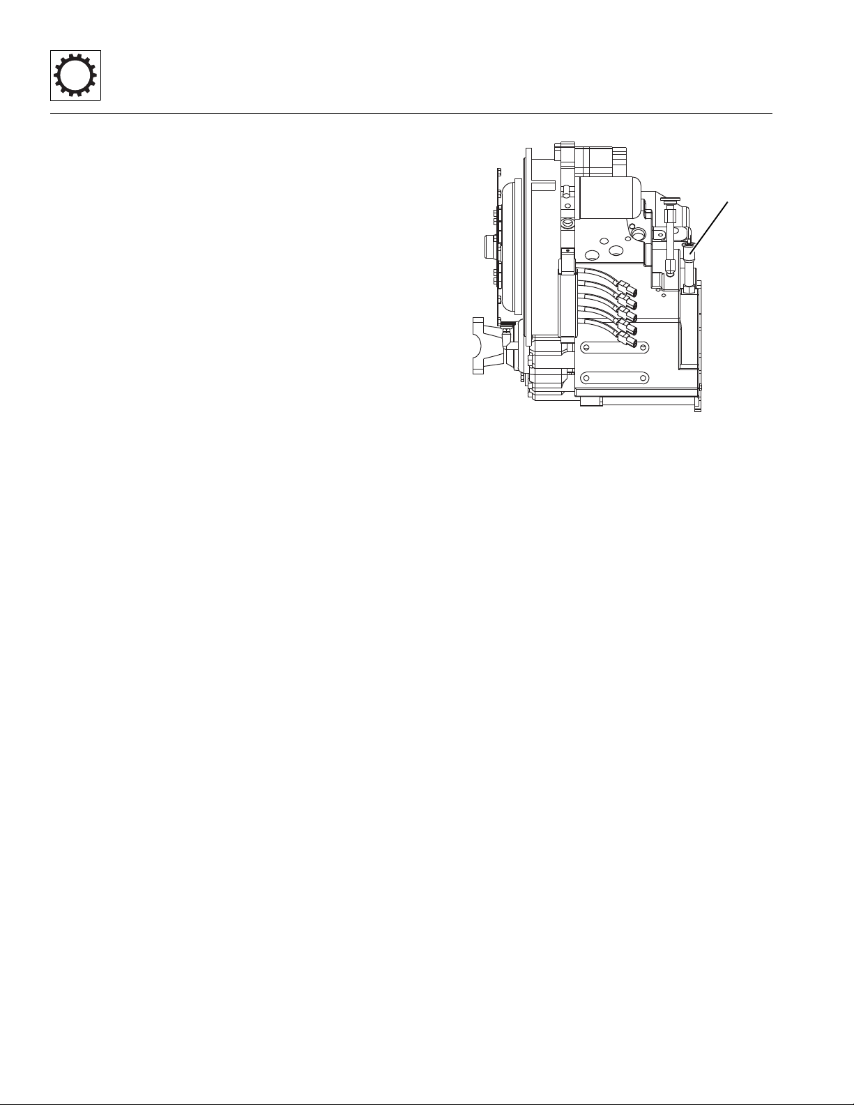
Transmission:
MZ0680
4
16. Remove the dipstick and add approximately 11,4
liters (3 Gallons) of hydraulic oil. Check the oil level
by taking intermittent dipstick readings as outlined in
the appropriate Operation & Safety Manual. DO
NOT overfill. Reinstall the dipstick when finished.
17. Remove the fill plug on the transfer case. Fill the
transmission drop box. Refer to Section 2.4, “Fluids,
Lubricants and Capacities.” Install and tighten drop
box fill plug.
18. Install the belly pan under the engine.
19. Install the engine cover.
20. Install the battery and reconnect the positive (+) and
negative (-) cables.
21. Close and secure the engine cover.
22. Remove the Do Not Operate Tags from both the
ignition key switch and the steering wheel.
6.5.4 After Transmission Service or
Replacement
Refer to the Dana Spicer Transmission Repair Manual
which can be obtained by calling your local JLG
Distributor.
In General:
1. Check the transmission oil level and add oil as
required.
2. Check the transmission drop box oil level and add oil
as required.
3. Install a new transmission filter.
4. Check the torque on the drive shaft yoke capscrews.
5. Wear suitable eye protection. When an overhauled
or repaired transmission is installed, thoroughly
clean the oil cooler lines to and from the
transmission.
6. Drain and flush the entire system.
7. Disconnect and clean all transmission cooler hoses.
When possible, remove transmission lines from the
machine for cleaning.
8. Thoroughly clean transmission filter screens and
cases, and replace transmission filter elements.
9. Thoroughly clean transmission oil cooler.
10. Reassemble all components and fill the transmission
through the dipstick tube opening (4). Remove the
dipstick and fill with approximately 11 liters
(2.5 gallons) of hydraulic. Check the level by taking
intermittent dipstick readings as outlined in the
appropriate Operation & Safety Manual. DO NOT
overfill. Reinstall the dipstick when finished.
11. Run the engine for two minutes at idle to help prime
the torque convertor and the transmission oil lines.
12. Recheck the level of the oil in the transmission with
the engine running at idle.
13. Add hydraulic oil as necessary to bring the oil level
up until it reaches the FULL mark on the dipstick.
Recheck the oil level when it reaches operating
temperature 83-94°C (180-200°F).
14. Recheck all drain plugs, lines, connections, etc. for
leaks, and tighten where necessary.
6-6
3508PS, 3509PS, 3512PS, 3513PS, 4008PS, 4009PS, 4012PS, 4013PS, 4017PS, 40.8, 40.9

Transmission:
6.6 TROUBLESHOOTING
The transmission should be checked, serviced and
repaired only by experienced service technicians who are
This section provides an easy reference guide covering
the most common problems that may occur during
aware of all safety instructions and particular component
features.
operation of the transmission.
Note: Contact the JLG Service Department if internal
transmission repair is required during the warranty
period.
Problem Cause Remedy
1. Transmission will not engage
or will not shift properly.
1. Oil level too high or low. 1. Fill transmission to correct level
with Mobilfluid 424
Grade 46. (Refer to Section 2.4,
“Fluids, Lubricants and
Capacities.”)
2. Transmission cont rol lever not
functioning properly and/or a
2. Refer to Section 9.7.1, “Cab
Harness Electric al Schematic.”
fault in the wiring
harness.Transmission control
lever not functioning properly
and/or a fault in the wiring
harness.
®
ISO
3. Transmission valve body
solenoids not functioning
3. Refer to Section 9.7.1, “Cab
Harness Electric al Schematic.”
properly.
4. Pilot-operated shift valves not
operating properly.
4. Clean the valve spool and
housing. Replace return spring
as needed.
5. Pump output pressure low. 5. Refer to Section 6.6,
“Troubleshooting,” Problem 2.
“Low or no pump flow or
pressure.”
6. Clutch piston o-rings damaged. 6. Replace o-rings.
7. Clutch discs worn or damaged. 7. Replace clutch discs.
8. Coupling shafts or gear teeth
8. Replace couplings.
damaged.
3508PS, 3509PS, 3512PS, 3513PS, 4008PS, 4009PS, 4012PS, 4013PS, 4017PS, 40.8, 40.9
6-7

Transmission:
Problem Cause Remedy
2. Low or no pump flow or
pressure.
1. Low oil level. 1. Fill transmission to correct level
®
with Mobilfluid 424
ISO
Grade 46. (Refer to Section 2.4,
“Fluids, Lubricants and
Capacities.”)
2. Transmission filled with incorrect
oil, or oil contaminated.
2. Drain transmission and fill to
correct level with Mobilflu id 424
ISO Grade 46. (Refer Section
2.4, “Fluids, Lubricants and
Capacities.”)
3. Pump suction pipe screen
clogged.
3. Clean, repair and/or replace
suction pipe.
4. Central shaft damaged. 4. Replace central shaft.
5. Pump worn or damaged. 5. Repair or replace pump
assembly.
3. Low clutch pressure. 1. Incorrec t oil level. 1. Fill transmission to correct level
®
with Mobilfluid 424
ISO
Grade 46. Refer to Section 2.4,
“Fluids, Lubricants and
Capacities.”
2. Main pressure valve stuck open. 2. Clean the valve spool and
housing.
®
3. Broken or worn coupling shaft or
3. Replace coupling and/or o-rings.
piston o-rings.
4. Pressure reducing valve stuck
open.
4. Clean the valve spool and
housing.
4. Lack of power. 1. Park or service brake dragging. 1. Refer to Section 8.5, “Hydraulic
Schematics.”
2. Low engine rpm causes
converter stall.
2. Adjust the engine rpm to
specifications. Refer to DanaSpicer Service Manual.
3. Pump output pressure is low. 3. Refer to Section 6.6,
“Troubleshooting,” Problem 2.
“Low or no pump flow or
pressure.”
4. Clutch discs worn or damaged. 4. Replace clutch discs.
5. Transmission overheating. 5. Refer to Section 6.6,
“Troubleshooting,” Problem 5.
“Transmission overheating (oil
above 120° C (248° F)).”
6-8
3508PS, 3509PS, 3512PS, 3513PS, 4008PS, 4009PS, 4012PS, 4013PS, 4017PS, 40.8, 40.9

Problem Cause Remedy
Transmission:
5. Transmission overheating
(oil above 120° C (248° F)).
6. Grinding or “clunking” noise
from transmission.
1. Low oil level. 1. Fill transmission to correct level
®
with Mobilfluid 424
ISO
Grade 46. Refer to Section 2.4,
“Fluids, Lubricants and
Capacities.”
2. Clogged radiator. 2. Remo ve deb ris fro m the
radiator.
3. T ransmission fille d with incorrect
oil, or oil contaminated.
3. Drain transmission and fill to
correct level with Mobilfluid 424
ISO Grade 46. Refer to Section
2.4, “Fluids, Lubricants and
Capacities.”
4. Excessive “roading.” 4. Stop and idle the engine.
5. Restriction in oil cooler hoses. 5. Replace cooler hoses.
6. Pump worn or damaged. 6. Repair or replace pump
assembly.
7. Engine thermostat stuck. 7. Replace engine thermostat.
Refer to Section 7.4.2,
“Thermostat Replacement.”
1. Oil level too low. 1. Fill oil to correct level. Refer to
Section 2.4, “Fluids, Lubricants
and Capacities.”
®
2. T ransmission fille d with incorrect
oil.
2. Drain transmission and fill to
correct level with Mobilfluid 424
ISO Grade 46. Refer to Section
2.4, “Fluids, Lubricants and
Capacities.”
3. Incorrect clutch engagement. 3. Refer to Section 9.14.1,
“Transmission Solenoid Valves.”
4. Internal damage. 4. Repair or replace parts as
needed.
5. Broken diaphragm (flex plate). 5. Replace diaphragm (flex plate).
Refer to Section 6.5.1,
“Transmission Removal.”
6. Loose diaphragm (flex plate)
6. Tighten capscrews.
mounting capscrews.
®
3508PS, 3509PS, 3512PS, 3513PS, 4008PS, 4009PS, 4012PS, 4013PS, 4017PS, 40.8, 40.9
6-9

Transmission:
Problem Cause Remedy
7. Oil leaking from transmission. 1. Oil leaking from vent (high oil
level).
2. Drain plug loose and/or o-rings
damaged or missing.
3. Hose fittings loose. 3. Tighten fittings.
4. Oil leaking at valve bodies
(possible valve body gaskets
damaged or missing and/or
mounting capscrews not tigh t) .
5. Housing capscrews loose. 5. Tighten capscrews to 46 Nm
6. Oil leaking at pump (possible
pump-to-housing o-rings
missing or damaged, and/or
pump mounting capscrews not
tight).
1. Remo ve dr ain plug and dra in o il
as needed, until oil is at correct
level. Refer to Section 2.4,
“Fluids, Lubricants and
Capacities.” Replace o-rings as
needed and tighten plugs to
130 Nm (96 lb- ft ).
2. Replace o-rings as needed and
tighten plug to 35 Nm (26 lb-ft).
4. Replace gaskets and/or tighten
capscrews to 9,5 Nm (7 lb-ft).
(34 lb-ft).
6. Replace o-rings and/or tighten
capscrews to 115 Nm (85 lb-ft).
7. Oil leaking at converter bell
(possible converter leak and/or
input shaft seal damage).
8. Oil leaking at output shaft
(output shaft seal damaged).
9. Housing damaged. 9. Replace housing as needed.
7. Replace converter and/or input
shaft seal.
8. Replace output shaft seal.
6-10
3508PS, 3509PS, 3512PS, 3513PS, 4008PS, 4009PS, 4012PS, 4013PS, 4017PS, 40.8, 40.9

Section 7
Engine: Perkins 1104-42 & 1104-42T
Contents
PARAGRAPH TITLE PAGE
7.1 Introduction . . . . . . . . . . . . . . . . . . . . . . . . . . . . . . . . . . . . . . . . . . . . . . . . . . . . . . . 7-2
7.1.1 Disclaimer and Scope . . . . . . . . . . . . . . . . . . . . . . . . . . . . . . . . . . . . . . . . 7-2
7.1.2 Component Terminology . . . . . . . . . . . . . . . . . . . . . . . . . . . . . . . . . . . . . . 7-3
7.2 Engine Serial Number. . . . . . . . . . . . . . . . . . . . . . . . . . . . . . . . . . . . . . . . . . . . . . . 7-4
7.3 Specifications and Maintenance Information. . . . . . . . . . . . . . . . . . . . . . . . . . . . 7-4
7.4 Engine Cooling System . . . . . . . . . . . . . . . . . . . . . . . . . . . . . . . . . . . . . . . . . . . . . 7-4
7.4.1 Radiator Pressure Cap . . . . . . . . . . . . . . . . . . . . . . . . . . . . . . . . . . . . . . . 7-4
7.4.2 Thermostat Replacement . . . . . . . . . . . . . . . . . . . . . . . . . . . . . . . . . . . . . 7-4
7.4.3 Radiator/Oil Cooler and Coolant Heater Replacement. . . . . . . . . . . . . . . 7-5
7.5 Engine Electrical System . . . . . . . . . . . . . . . . . . . . . . . . . . . . . . . . . . . . . . . . . . . . 7-6
7.6 Fuel System . . . . . . . . . . . . . . . . . . . . . . . . . . . . . . . . . . . . . . . . . . . . . . . . . . . . . . . 7-6
7.6.1 Diesel Fuel . . . . . . . . . . . . . . . . . . . . . . . . . . . . . . . . . . . . . . . . . . . . . . . . 7-6
7.6.2 Fuel Tank. . . . . . . . . . . . . . . . . . . . . . . . . . . . . . . . . . . . . . . . . . . . . . . . . . 7-7
7.6.3 After Fuel System Service. . . . . . . . . . . . . . . . . . . . . . . . . . . . . . . . . . . . . 7-8
7.7 Engine Exhaust System . . . . . . . . . . . . . . . . . . . . . . . . . . . . . . . . . . . . . . . . . . . . . 7-8
7.8 Air Cleaner Assembly . . . . . . . . . . . . . . . . . . . . . . . . . . . . . . . . . . . . . . . . . . . . . . . 7-9
7.8.1 Air Cleaner Assembly Removal . . . . . . . . . . . . . . . . . . . . . . . . . . . . . . . . 7-9
7.8.2 Air Cleaner Assembly Installation. . . . . . . . . . . . . . . . . . . . . . . . . . . . . . . 7-9
7.9 Engine Replacement. . . . . . . . . . . . . . . . . . . . . . . . . . . . . . . . . . . . . . . . . . . . . . . . 7-9
7.9.1 Engine Removal . . . . . . . . . . . . . . . . . . . . . . . . . . . . . . . . . . . . . . . . . . . . 7-9
7.9.2 Engine Disassembly, Inspection and Service . . . . . . . . . . . . . . . . . . . . . . 7-10
7.9.3 Engine Installation. . . . . . . . . . . . . . . . . . . . . . . . . . . . . . . . . . . . . . . . . . . 7-11
7.10 Engine Drive Plate. . . . . . . . . . . . . . . . . . . . . . . . . . . . . . . . . . . . . . . . . . . . . . . . . . 7-12
7.10.1 Drive Plate Removal. . . . . . . . . . . . . . . . . . . . . . . . . . . . . . . . . . . . . . . . . 7-12
7.10.2 Drive Plate Installation . . . . . . . . . . . . . . . . . . . . . . . . . . . . . . . . . . . . . . . 7-12
7.11 Troubleshooting . . . . . . . . . . . . . . . . . . . . . . . . . . . . . . . . . . . . . . . . . . . . . . . . . . . 7-13
3508PS, 3509PS, 3512PS, 3513PS, 4008PS, 4009PS, 4012PS, 4013PS, 4017PS, 40.8, 40.9
7-1

Engine: Perkins 1104-42 & 1104-42T
7.1 INTRODUCTION
7.1.1 Disclaimer and Scope
These instructions are written for worldwide use. In
territories where legal requirements govern engine smoke
emission, noise, safety factors, etc., apply all instructions,
data and dimensions provided herein in such a way that
after maintenance, service and repair of the engine,
engine operation does not violate local regulations.
Note: These instructions cover only the routine
maintenance, removal, installation and troubleshooting
of the engine. For assistance with comprehensive
engine diagnosis, repair and component replacement,
contact your local Perkins Service partner.
A gradual running-in (break-in) of a new engine is not
necessary. Full load can be applied to a new engine as
soon as the engine is put into service and the coolant
temperature is at least 60° C (140° F). Extended lightload operation during the early life of the engine is not
recommended. DO NOT run the engine at high, no-load
speeds. DO NOT apply an overload to the engine.
7-2
3508PS, 3509PS, 3512PS, 3513PS, 4008PS, 4009PS, 4012PS, 4013PS, 4017PS, 40.8, 40.9
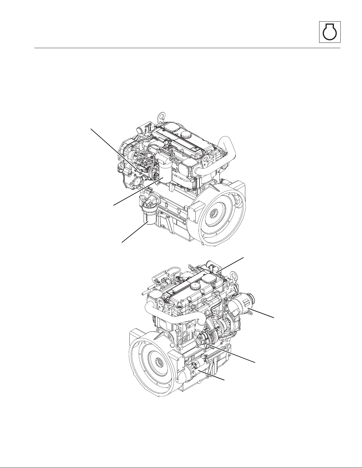
7.1.2 Component Terminology
MZ0070
TURBOCHARGER
FUEL INJECTION
PUMP
OIL FILTER
THERMOSTAT
FUEL FILTER
ALTERNATOR
STARTER
To understand the safety, operation and maintenance
information presented in this section, it is necessary that
the operator/mechanic be familiar with the names and
locations of the engine components. The following
illustration identifies the components that are referred to
throughout this section.
Engine: Perkins 1104-42 & 1104-42T
3508PS, 3509PS, 3512PS, 3513PS, 4008PS, 4009PS, 4012PS, 4013PS, 4017PS, 40.8, 40.9
7-3

Engine: Perkins 1104-42 & 1104-42T
MZ2180
1
7.2 ENGINE SERIAL NUMBER
The Perkins serial number is stamped on a plate which is
secured to the engine block, near the fuel injector pump.
Information contained in the serial number is required in
correspondence with the engine manufacturer.
7.3 SPECIFICATIONS AND MAINTENANCE INFORMATION
For engine, coolant and oil specifications, and
maintenance information, refer to Section 2, “General
Information and Specification s . ”
Note: These instructions cover only the routine
maintenance, removal, installation and troubleshooting
of the engine. Refer to your local Perkins Engine
Distributor for assistance with comprehensive engine
diagnosis, repair and component replacement.
7.4 ENGINE COOLING SYSTEM
7.4.1 Radiator Pressure Cap
For a 99° C (210° F) system, use a 90 kPa (13 psi)
radiator cap. An incorrect or malfunctioning cap can
result in the loss of coolant and a hot-running engine.
a. Thermostat Removal
1. Park the machine on a firm, level surface, level the
machine, fully retract the boom, lower the boom,
place the transmission control lever in
(N) NEUTRAL, engage the park brake and shut the
engine OFF.
2. Place a Do Not Operate Tag on both the ignition key
switch and steering wheel, stati ng that the machi ne
should not be operated.
3. Open the engine cover. Allow the system fluids to
cool.
4. Properly disconnect the battery.
5. Slowly turn the radiator cap to the first stop and allow
any pressure to escape. Remove the radiator cap.
6. Place a funnel at the base of the radiator to channel
the drained coolant into the container. Loosen the
drain plug and slowly remove to allow the coolant to
drain. Transfer the coolant into a properly labeled
container. Dispose of properly if coolant needs to be
replaced. Replace the radiator drain plug.
7.4.2 Thermostat Replacement
Before considering thermostat replacement, check the
coolant level, fan belt tension and instrument cluster
temperature indicator.
• If the engine seems to take a long time to warm up,
the thermostat may be stuck in the open position
and requires replacement.
• If the engine runs hot, check the temperature of the
upper radiator hose.
• If the hose is not hot, the thermostat may be stuck in
the closed position.
• If the engine has overheated, performance may
suffer, indicating other damage including a leaking
cylinder head gasket, cracked cylinder head or
block, and/or other internal engine damage.
7. Remove the two capscrews securing the thermostat
housing (1) to the engine.
8. Remove the thermostat housing, old gasket and
thermostat. Clean all gasket surfaces. DO NOT let
any debris into the thermostat opening.
Note: ALWAYS use the correct thermostat and install a
new gasket. NEVER operate the engine without a
thermostat, or engine damage will result.
7-4
3508PS, 3509PS, 3512PS, 3513PS, 4008PS, 4009PS, 4012PS, 4013PS, 4017PS, 40.8, 40.9
 Loading...