


JLG M4069 Service Manual
Service & Maintenance Manual
Models
3369LE
4069LE
M3369
M4069
S/N-0200230092 to
Present
3121639
June 10, 2014

INTRODUCTION - MAINTENANCE SAFETY PRECAUTIONS
INTRODUCTION - MAINTENANCE SAFETY PRECAUTIONS
AGENERAL
This section contains the general safety precautions
which must be observed during maintenance of the
aerial platform. It is of utmost importance that maintenance personnel pay strict attention to these warnings and precautions to avoid possible injury to
themselves or others, or damage to the equipment.
A maintenance program must be followed to ensure
that the machine is safe to operate.
MODIFICATION OF THE MACHINE WITHOUT CERTIFICATION BY A RESPONSIBLE AUTHORITY THAT THE
MACHINE IS AT LEAST AS SAFE AS ORIGINALLY
MANUFACTURED, IS A SAFETY VIOLATION.
The specific precautions to be observed during
maintenance are inserted at the appropriate point in
the manual. These precautions are, for the most
part, those that apply when servicing hydraulic and
larger machine component parts.
Your safety, and that of others, is the first consideration when engaging in the maintenance of equipment. Always be conscious of weight. Never attempt
to move heavy parts without the aid of a mechanical
device. Do not allow heavy objects to rest in an
unstable position. When raising a portion of the
equipment, ensure that adequate support is provided.
SINCE THE MACHINE MANUFACTURER HAS NO
DIRECT CONTROL OVER THE FIELD INSPECTION
AND MAINTENANCE, SAFETY IN THIS AREA RESPONSIBILITY OF THE OWNER/OPERATOR.
B HYDRAULIC SYSTEM SAFETY
It should be noted that the machines hydraulic systems operate at extremely high potentially dangerous pressures. Every effort should be made to
relieve any system pressure prior to disconnecting
or removing any portion of the system.
CMAINTENANCE
FAILURE TO COMPLY WITH SAFETY PRECAUTIONS
LISTED IN THIS SECTION MAY RESULT IN MACHINE
DAMAGE, PERSONNEL INJURY OR DEATH AND IS A
SAFETY VIOLATION.
• NO SMOKING IS MANDATORY. NEVER REFUEL DURING ELECTRICAL STORMS. ENSURE THAT FUEL CAP
IS CLOSED AND SECURE AT ALL OTHER TIMES.
• REMOVE ALL RINGS, WATCHES AND JEWELRY WHEN
PERFORMING ANY MAINTENANCE.
• DO NOT WEAR LONG HAIR UNRESTRAINED, OR
LOOSE-FITTING CLOTHING AND NECKTIES WHICH
ARE APT TO BECOME CAUGHT ON OR ENTANGLED
IN EQUIPMENT.
• OBSERVE AND OBEY ALL WARNINGS AND CAUTIONS
ON MACHINE AND IN SERVICE MANUAL.
• KEEP OIL, GREASE, WATER, ETC. WIPED FROM
STANDING SURFACES AND HAND HOLDS.
•USE CAUTION WHEN CHECKING A HOT, PRESSURIZED COOLANT SYSTEM.
• NEVER WORK UNDER AN ELEVATED SIZZOR UNTIL
PLATFORM HAS BEEN SAFELY RESTRAINED FROM
ANY MOVEMENT BY BLOCKING OR OVERHEAD
SLING, OR BOOM SAFETY PROP HAS BEEN
ENGAGED.
• BEFORE MAKING ADJUSTMENTS, LUBRICATING OR
PERFORMING ANY OTHER MAINTENANCE, SHUT
OFF ALL POWER CONTROLS.
• BATTERY SHOULD ALWAYS BE DISCONNECTED DURING REPLACEMENT OF ELECTRICAL COMPONENTS.
• KEEP ALL SUPPORT EQUIPMENT AND ATTACHMENTS STOWED IN THEIR PROPER PLACE.
• USE ONLY APPROVED, NONFLAMMABLE CLEANING
SOLVENTS.
Relieve system pressure by cycling the applicable
control several times with the engine stopped and
ignition on, to direct any line pressure back into the
reservoir. Pressure feed lines to system components
can then be disconnected with minimal fluid loss.
3121639 – JLG Lift – a

INTRODUCTION - MAINTENANCE SAFETY PRECAUTIONS
REVISION LOG
Original Issue . . . . . . . . . . . . . . . . . .June 10, 2014
b – JLG Lift – 3121639

TABLE OF CONTENTS
TABLE OF CONTENTS
SUBJECT - SECTION, PARAGRAPH PAGE NO.
SECTION - INTRODUCTION - MAINTENANCE SAFETY PRECAUTIONS
A General . . . . . . . . . . . . . . . . . . . . . . . . . . . . . . . . . . . . . . . . . . . . . . . . . . . . . . . . . . . . . . . . . . . . . . A
B Hydraulic System Safety . . . . . . . . . . . . . . . . . . . . . . . . . . . . . . . . . . . . . . . . . . . . . . . . . . . . . . . . . A
C Maintenance . . . . . . . . . . . . . . . . . . . . . . . . . . . . . . . . . . . . . . . . . . . . . . . . . . . . . . . . . . . . . . . . . .A
SECTION 1 - SPECIFICATIONS
1.1 Specifications . . . . . . . . . . . . . . . . . . . . . . . . . . . . . . . . . . . . . . . . . . . . . . . . . . . . . . . . . . . . . . . . .1-1
1.2 Component Data . . . . . . . . . . . . . . . . . . . . . . . . . . . . . . . . . . . . . . . . . . . . . . . . . . . . . . . . . . . . . . .1-2
Dimensional Data. . . . . . . . . . . . . . . . . . . . . . . . . . . . . . . . . . . . . . . . . . . . . . . . . . . . . . . . . . 1-2
Battery Charger . . . . . . . . . . . . . . . . . . . . . . . . . . . . . . . . . . . . . . . . . . . . . . . . . . . . . . . . . . . 1-2
Batteries . . . . . . . . . . . . . . . . . . . . . . . . . . . . . . . . . . . . . . . . . . . . . . . . . . . . . . . . . . . . . . . . . 1-2
Drive System . . . . . . . . . . . . . . . . . . . . . . . . . . . . . . . . . . . . . . . . . . . . . . . . . . . . . . . . . . . . . 1-2
Steer System . . . . . . . . . . . . . . . . . . . . . . . . . . . . . . . . . . . . . . . . . . . . . . . . . . . . . . . . . . . . . 1-2
Hydraulic Pump/Electric Motor Assembly. . . . . . . . . . . . . . . . . . . . . . . . . . . . . . . . . . . . . . . 1-2
Tires . . . . . . . . . . . . . . . . . . . . . . . . . . . . . . . . . . . . . . . . . . . . . . . . . . . . . . . . . . . . . . . . . . . . 1-3
Engine (Generator) . . . . . . . . . . . . . . . . . . . . . . . . . . . . . . . . . . . . . . . . . . . . . . . . . . . . . . . . 1-3
1.3 Capacities . . . . . . . . . . . . . . . . . . . . . . . . . . . . . . . . . . . . . . . . . . . . . . . . . . . . . . . . . . . . . . . . . . . .1-4
1.4 Pressure Settings . . . . . . . . . . . . . . . . . . . . . . . . . . . . . . . . . . . . . . . . . . . . . . . . . . . . . . . . . . . . . .1-4
1.5 Torque Specifications . . . . . . . . . . . . . . . . . . . . . . . . . . . . . . . . . . . . . . . . . . . . . . . . . . . . . . . . . . .1-4
1.6 Cylinder Specifications . . . . . . . . . . . . . . . . . . . . . . . . . . . . . . . . . . . . . . . . . . . . . . . . . . . . . . . . . .1-4
1.7 Major Component Weights . . . . . . . . . . . . . . . . . . . . . . . . . . . . . . . . . . . . . . . . . . . . . . . . . . . . . .1-4
1.8 Critical Stability Weights . . . . . . . . . . . . . . . . . . . . . . . . . . . . . . . . . . . . . . . . . . . . . . . . . . . . . . . . .1-4
1.9 Lubrication . . . . . . . . . . . . . . . . . . . . . . . . . . . . . . . . . . . . . . . . . . . . . . . . . . . . . . . . . . . . . . . . . . .1-5
Lubrication Specifications . . . . . . . . . . . . . . . . . . . . . . . . . . . . . . . . . . . . . . . . . . . . . . . . . . 1-5
1.10 Serial Number Locations. . . . . . . . . . . . . . . . . . . . . . . . . . . . . . . . . . . . . . . . . . . . . . . . . . . . . . . . .1-7
1.11 Torque Charts . . . . . . . . . . . . . . . . . . . . . . . . . . . . . . . . . . . . . . . . . . . . . . . . . . . . . . . . . . . . . . . . . 1-8
SECTION 2 - GENERAL
2.1 Machine Preparation, Inspection, and Maintenance . . . . . . . . . . . . . . . . . . . . . . . . . . . . . . . . . . . 2-1
General. . . . . . . . . . . . . . . . . . . . . . . . . . . . . . . . . . . . . . . . . . . . . . . . . . . . . . . . . . . . . . . . . . 2-1
Preparation, Inspection, and Maintenance . . . . . . . . . . . . . . . . . . . . . . . . . . . . . . . . . . . . . . 2-1
Pre-Start Inspection . . . . . . . . . . . . . . . . . . . . . . . . . . . . . . . . . . . . . . . . . . . . . . . . . . . . . . . . 2-1
Pre-Delivery Inspection and Frequent Inspection . . . . . . . . . . . . . . . . . . . . . . . . . . . . . . . . . 2-1
Annual Machine Inspection . . . . . . . . . . . . . . . . . . . . . . . . . . . . . . . . . . . . . . . . . . . . . . . . . . 2-1
Preventative Maintenance . . . . . . . . . . . . . . . . . . . . . . . . . . . . . . . . . . . . . . . . . . . . . . . . . . . 2-1
2.2 Service and Guidelines . . . . . . . . . . . . . . . . . . . . . . . . . . . . . . . . . . . . . . . . . . . . . . . . . . . . . . . . . .2-2
General. . . . . . . . . . . . . . . . . . . . . . . . . . . . . . . . . . . . . . . . . . . . . . . . . . . . . . . . . . . . . . . . . . 2-2
Safety and Workmanship . . . . . . . . . . . . . . . . . . . . . . . . . . . . . . . . . . . . . . . . . . . . . . . . . . . 2-2
Cleanliness. . . . . . . . . . . . . . . . . . . . . . . . . . . . . . . . . . . . . . . . . . . . . . . . . . . . . . . . . . . . . . . 2-2
Components Removal and Installation . . . . . . . . . . . . . . . . . . . . . . . . . . . . . . . . . . . . . . . . . 2-2
Component Disassembly and Reassembly . . . . . . . . . . . . . . . . . . . . . . . . . . . . . . . . . . . . . 2-3
Pressure-Fit Parts. . . . . . . . . . . . . . . . . . . . . . . . . . . . . . . . . . . . . . . . . . . . . . . . . . . . . . . . . . 2-3
Bearings . . . . . . . . . . . . . . . . . . . . . . . . . . . . . . . . . . . . . . . . . . . . . . . . . . . . . . . . . . . . . . . . . 2-3
Gaskets . . . . . . . . . . . . . . . . . . . . . . . . . . . . . . . . . . . . . . . . . . . . . . . . . . . . . . . . . . . . . . . . . 2-3
Bolt Usage and Torque Application . . . . . . . . . . . . . . . . . . . . . . . . . . . . . . . . . . . . . . . . . . . 2-3
Hydraulic Lines and Electrical Wiring . . . . . . . . . . . . . . . . . . . . . . . . . . . . . . . . . . . . . . . . . . 2-3
Hydraulic System. . . . . . . . . . . . . . . . . . . . . . . . . . . . . . . . . . . . . . . . . . . . . . . . . . . . . . . . . . 2-3
Lubrication . . . . . . . . . . . . . . . . . . . . . . . . . . . . . . . . . . . . . . . . . . . . . . . . . . . . . . . . . . . . . . . 2-3
Battery . . . . . . . . . . . . . . . . . . . . . . . . . . . . . . . . . . . . . . . . . . . . . . . . . . . . . . . . . . . . . . . . . . 2-3
Lubrication and Servicing . . . . . . . . . . . . . . . . . . . . . . . . . . . . . . . . . . . . . . . . . . . . . . . . . . . 2-3
2.3 Lubrication and Information . . . . . . . . . . . . . . . . . . . . . . . . . . . . . . . . . . . . . . . . . . . . . . . . . . . . . .2-4
Hydraulic System. . . . . . . . . . . . . . . . . . . . . . . . . . . . . . . . . . . . . . . . . . . . . . . . . . . . . . . . . . 2-4
Hydraulic Oil . . . . . . . . . . . . . . . . . . . . . . . . . . . . . . . . . . . . . . . . . . . . . . . . . . . . . . . . . . . . . 2-4
3121639 – JLG Lift – i

TABLE OF CONTENTS
Changing Hydraulic Oil . . . . . . . . . . . . . . . . . . . . . . . . . . . . . . . . . . . . . . . . . . . . . . . . . . . . . 2-4
Lubrication Specifications . . . . . . . . . . . . . . . . . . . . . . . . . . . . . . . . . . . . . . . . . . . . . . . . . . . 2-4
2.4 Cylinder Drift Test . . . . . . . . . . . . . . . . . . . . . . . . . . . . . . . . . . . . . . . . . . . . . . . . . . . . . . . . . . . . . .2-5
Platform Drift . . . . . . . . . . . . . . . . . . . . . . . . . . . . . . . . . . . . . . . . . . . . . . . . . . . . . . . . . . . . . 2-5
Cylinder Drift . . . . . . . . . . . . . . . . . . . . . . . . . . . . . . . . . . . . . . . . . . . . . . . . . . . . . . . . . . . . . 2-5
2.5 Pins and Composite Bearing Repair Guidelines . . . . . . . . . . . . . . . . . . . . . . . . . . . . . . . . . . . . . .2-5
2.6 Preventive Maintenance and Inspection Schedule . . . . . . . . . . . . . . . . . . . . . . . . . . . . . . . . . . . . 2-6
SECTION 3 - CHASSIS & SCISSOR ARMS
3.1 Calibrations . . . . . . . . . . . . . . . . . . . . . . . . . . . . . . . . . . . . . . . . . . . . . . . . . . . . . . . . . . . . . . . . . . . 3-1
Elevation Sensor Calibration . . . . . . . . . . . . . . . . . . . . . . . . . . . . . . . . . . . . . . . . . . . . . . . . . 3-1
Speed Sensor . . . . . . . . . . . . . . . . . . . . . . . . . . . . . . . . . . . . . . . . . . . . . . . . . . . . . . . . . . . . 3-1
Tilt Sensor Calibration: . . . . . . . . . . . . . . . . . . . . . . . . . . . . . . . . . . . . . . . . . . . . . . . . . . . . . 3-1
Joystick Calibration . . . . . . . . . . . . . . . . . . . . . . . . . . . . . . . . . . . . . . . . . . . . . . . . . . . . . . . . 3-2
3.2 Tilt Sensor . . . . . . . . . . . . . . . . . . . . . . . . . . . . . . . . . . . . . . . . . . . . . . . . . . . . . . . . . . . . . . . . . . . . 3-3
Tilt Sensor, JLG P/N 4000021: . . . . . . . . . . . . . . . . . . . . . . . . . . . . . . . . . . . . . . . . . . . . . . . 3-3
3.3 Battery Maintenance and Charging . . . . . . . . . . . . . . . . . . . . . . . . . . . . . . . . . . . . . . . . . . . . . . . . 3-4
Battery Maintenance, Quarterly. . . . . . . . . . . . . . . . . . . . . . . . . . . . . . . . . . . . . . . . . . . . . . . 3-4
Optional On-Board Generator . . . . . . . . . . . . . . . . . . . . . . . . . . . . . . . . . . . . . . . . . . . . . . . . 3-4
Battery Charging (On Board Charger) (MAC). . . . . . . . . . . . . . . . . . . . . . . . . . . . . . . . . . . . 3-4
Charging Sequence of Remote LED Card . . . . . . . . . . . . . . . . . . . . . . . . . . . . . . . . . . . . . . 3-5
Battery Charger (Delta-Q) . . . . . . . . . . . . . . . . . . . . . . . . . . . . . . . . . . . . . . . . . . . . . . . . . . . 3-5
Battery Charger Maintenance . . . . . . . . . . . . . . . . . . . . . . . . . . . . . . . . . . . . . . . . . . . . . . . . 3-6
Battery Charger Troubleshooting . . . . . . . . . . . . . . . . . . . . . . . . . . . . . . . . . . . . . . . . . . . . . 3-7
Battery Temperature Sensor . . . . . . . . . . . . . . . . . . . . . . . . . . . . . . . . . . . . . . . . . . . . . . . . . 3-9
Removing the Battery Box . . . . . . . . . . . . . . . . . . . . . . . . . . . . . . . . . . . . . . . . . . . . . . . . . . . 3-10
3.4 Generator. . . . . . . . . . . . . . . . . . . . . . . . . . . . . . . . . . . . . . . . . . . . . . . . . . . . . . . . . . . . . . . . . . . . . 3-11
Timing Sequences. . . . . . . . . . . . . . . . . . . . . . . . . . . . . . . . . . . . . . . . . . . . . . . . . . . . . . . . . 3-13
To Connect the JLG Control System Analyzer to the Generator . . . . . . . . . . . . . . . . . . . . . 3-15
Alarms and Fault Flash Codes . . . . . . . . . . . . . . . . . . . . . . . . . . . . . . . . . . . . . . . . . . . . . . . 3-15
Output Current and Voltage Settings . . . . . . . . . . . . . . . . . . . . . . . . . . . . . . . . . . . . . . . . . . 3-16
Priming the Fuel Line. . . . . . . . . . . . . . . . . . . . . . . . . . . . . . . . . . . . . . . . . . . . . . . . . . . . . . . 3-16
3.5 Supplementary Fuse For APU . . . . . . . . . . . . . . . . . . . . . . . . . . . . . . . . . . . . . . . . . . . . . . . . . . . .3-17
Tools And Material . . . . . . . . . . . . . . . . . . . . . . . . . . . . . . . . . . . . . . . . . . . . . . . . . . . . . . . . . 3-17
Procedure . . . . . . . . . . . . . . . . . . . . . . . . . . . . . . . . . . . . . . . . . . . . . . . . . . . . . . . . . . . . . . . 3-17
3.6 Joystick Controller. . . . . . . . . . . . . . . . . . . . . . . . . . . . . . . . . . . . . . . . . . . . . . . . . . . . . . . . . . . . . . 3-19
Power Controller . . . . . . . . . . . . . . . . . . . . . . . . . . . . . . . . . . . . . . . . . . . . . . . . . . . . . . . . . . 3-21
3.7 Towing . . . . . . . . . . . . . . . . . . . . . . . . . . . . . . . . . . . . . . . . . . . . . . . . . . . . . . . . . . . . . . . . . . . . . . . 3-21
Disengaging for Towing . . . . . . . . . . . . . . . . . . . . . . . . . . . . . . . . . . . . . . . . . . . . . . . . . . . . 3-21
Engaging after Towing is Complete . . . . . . . . . . . . . . . . . . . . . . . . . . . . . . . . . . . . . . . . . . . 3-22
3.8 Drive Hub. . . . . . . . . . . . . . . . . . . . . . . . . . . . . . . . . . . . . . . . . . . . . . . . . . . . . . . . . . . . . . . . . . . . .3-24
Disassembly. . . . . . . . . . . . . . . . . . . . . . . . . . . . . . . . . . . . . . . . . . . . . . . . . . . . . . . . . . . . . . 3-24
Disassembly of Cover Unit (8). . . . . . . . . . . . . . . . . . . . . . . . . . . . . . . . . . . . . . . . . . . . . . . . 3-24
Disassembly of First Stage Planetary Assembly. . . . . . . . . . . . . . . . . . . . . . . . . . . . . . . . . . 3-24
Disassembly of the Second Stage Planet Gears (1). . . . . . . . . . . . . . . . . . . . . . . . . . . . . . . 3-24
3.9 Drive Brake - MICO . . . . . . . . . . . . . . . . . . . . . . . . . . . . . . . . . . . . . . . . . . . . . . . . . . . . . . . . . . . . . 3-26
Disassembly. . . . . . . . . . . . . . . . . . . . . . . . . . . . . . . . . . . . . . . . . . . . . . . . . . . . . . . . . . . . . . 3-26
Assembly . . . . . . . . . . . . . . . . . . . . . . . . . . . . . . . . . . . . . . . . . . . . . . . . . . . . . . . . . . . . . . . . 3-26
Bleeding. . . . . . . . . . . . . . . . . . . . . . . . . . . . . . . . . . . . . . . . . . . . . . . . . . . . . . . . . . . . . . . . . 3-26
3.10 Torque Hub . . . . . . . . . . . . . . . . . . . . . . . . . . . . . . . . . . . . . . . . . . . . . . . . . . . . . . . . . . . . . . . . . .3-27
Roll Test . . . . . . . . . . . . . . . . . . . . . . . . . . . . . . . . . . . . . . . . . . . . . . . . . . . . . . . . . . . . . . . . . 3-28
Leak Test (Main Unit). . . . . . . . . . . . . . . . . . . . . . . . . . . . . . . . . . . . . . . . . . . . . . . . . . . . . . . 3-28
Tightening and Torquing Bolts . . . . . . . . . . . . . . . . . . . . . . . . . . . . . . . . . . . . . . . . . . . . . . . 3-28
Main Disassembly . . . . . . . . . . . . . . . . . . . . . . . . . . . . . . . . . . . . . . . . . . . . . . . . . . . . . . . . . 3-29
Output Carrier Disassembly . . . . . . . . . . . . . . . . . . . . . . . . . . . . . . . . . . . . . . . . . . . . . . . . . 3-31
Input Carrier Disassembly . . . . . . . . . . . . . . . . . . . . . . . . . . . . . . . . . . . . . . . . . . . . . . . . . . 3-32
Hub-Spindle Disassembly . . . . . . . . . . . . . . . . . . . . . . . . . . . . . . . . . . . . . . . . . . . . . . . . . . 3-33
ii – JLG Lift – 3121639

Cover Disassembly . . . . . . . . . . . . . . . . . . . . . . . . . . . . . . . . . . . . . . . . . . . . . . . . . . . . . . . . 3-34
Input Carrier Sub-Assembly . . . . . . . . . . . . . . . . . . . . . . . . . . . . . . . . . . . . . . . . . . . . . . . . . 3-35
Output Carrier Sub-Assembly . . . . . . . . . . . . . . . . . . . . . . . . . . . . . . . . . . . . . . . . . . . . . . . . 3-36
Hub-Spindle Sub-Assembly . . . . . . . . . . . . . . . . . . . . . . . . . . . . . . . . . . . . . . . . . . . . . . . . 3-37
Cover Sub-Assembly . . . . . . . . . . . . . . . . . . . . . . . . . . . . . . . . . . . . . . . . . . . . . . . . . . . . . . 3-38
Main Assembly. . . . . . . . . . . . . . . . . . . . . . . . . . . . . . . . . . . . . . . . . . . . . . . . . . . . . . . . . . . . 3-39
SECTION 4 - HYDRAULICS
4.1 Servicing and Maintenance Guidelines . . . . . . . . . . . . . . . . . . . . . . . . . . . . . . . . . . . . . . . . . . . . .4-1
General. . . . . . . . . . . . . . . . . . . . . . . . . . . . . . . . . . . . . . . . . . . . . . . . . . . . . . . . . . . . . . . . . . 4-1
Safety and Workmanship . . . . . . . . . . . . . . . . . . . . . . . . . . . . . . . . . . . . . . . . . . . . . . . . . . . 4-1
Cleanliness. . . . . . . . . . . . . . . . . . . . . . . . . . . . . . . . . . . . . . . . . . . . . . . . . . . . . . . . . . . . . . . 4-1
Component Removal and Installation . . . . . . . . . . . . . . . . . . . . . . . . . . . . . . . . . . . . . . . . . . 4-1
Component Disassembly and Reassembly . . . . . . . . . . . . . . . . . . . . . . . . . . . . . . . . . . . . . 4-1
Pressure Fit Parts. . . . . . . . . . . . . . . . . . . . . . . . . . . . . . . . . . . . . . . . . . . . . . . . . . . . . . . . . . 4-1
Bearings . . . . . . . . . . . . . . . . . . . . . . . . . . . . . . . . . . . . . . . . . . . . . . . . . . . . . . . . . . . . . . . . . 4-1
Gaskets . . . . . . . . . . . . . . . . . . . . . . . . . . . . . . . . . . . . . . . . . . . . . . . . . . . . . . . . . . . . . . . . . 4-1
Bolt Usage and Torque Application . . . . . . . . . . . . . . . . . . . . . . . . . . . . . . . . . . . . . . . . . . . 4-1
Hydraulic Lines and Electrical Wiring . . . . . . . . . . . . . . . . . . . . . . . . . . . . . . . . . . . . . . . . . . 4-2
Hydraulic System. . . . . . . . . . . . . . . . . . . . . . . . . . . . . . . . . . . . . . . . . . . . . . . . . . . . . . . . . . 4-2
Lubrication . . . . . . . . . . . . . . . . . . . . . . . . . . . . . . . . . . . . . . . . . . . . . . . . . . . . . . . . . . . . . . . 4-2
Batteries . . . . . . . . . . . . . . . . . . . . . . . . . . . . . . . . . . . . . . . . . . . . . . . . . . . . . . . . . . . . . . . . . 4-2
Lubrication and Servicing . . . . . . . . . . . . . . . . . . . . . . . . . . . . . . . . . . . . . . . . . . . . . . . . . . . 4-2
4.2 Lubrication Information . . . . . . . . . . . . . . . . . . . . . . . . . . . . . . . . . . . . . . . . . . . . . . . . . . . . . . . . . .4-2
Hydraulic System. . . . . . . . . . . . . . . . . . . . . . . . . . . . . . . . . . . . . . . . . . . . . . . . . . . . . . . . . . 4-2
Hydraulic Oil . . . . . . . . . . . . . . . . . . . . . . . . . . . . . . . . . . . . . . . . . . . . . . . . . . . . . . . . . . . . . 4-2
Changing Hydraulic Oil . . . . . . . . . . . . . . . . . . . . . . . . . . . . . . . . . . . . . . . . . . . . . . . . . . . . . 4-2
Lubrication Specifications . . . . . . . . . . . . . . . . . . . . . . . . . . . . . . . . . . . . . . . . . . . . . . . . . . . 4-3
4.3 Cylinders - Theory of Operation . . . . . . . . . . . . . . . . . . . . . . . . . . . . . . . . . . . . . . . . . . . . . . . . . . .4-3
4.4 Valves - Theory of Operation. . . . . . . . . . . . . . . . . . . . . . . . . . . . . . . . . . . . . . . . . . . . . . . . . . . . . . 4-3
Control Valves . . . . . . . . . . . . . . . . . . . . . . . . . . . . . . . . . . . . . . . . . . . . . . . . . . . . . . . . . . . . 4-3
4.5 Component Functional Description . . . . . . . . . . . . . . . . . . . . . . . . . . . . . . . . . . . . . . . . . . . . . . . .4-3
Hydraulic Pump . . . . . . . . . . . . . . . . . . . . . . . . . . . . . . . . . . . . . . . . . . . . . . . . . . . . . . . . . . . 4-3
Manual Descent . . . . . . . . . . . . . . . . . . . . . . . . . . . . . . . . . . . . . . . . . . . . . . . . . . . . . . . . . . . 4-3
4.6 Wear Pads . . . . . . . . . . . . . . . . . . . . . . . . . . . . . . . . . . . . . . . . . . . . . . . . . . . . . . . . . . . . . . . . . . . .4-3
4.7 Motor Controller - Modes of Operation. . . . . . . . . . . . . . . . . . . . . . . . . . . . . . . . . . . . . . . . . . . . . .4-4
Traction Motor (Drive) . . . . . . . . . . . . . . . . . . . . . . . . . . . . . . . . . . . . . . . . . . . . . . . . . . . . . . 4-4
Pump Motor (LIft). . . . . . . . . . . . . . . . . . . . . . . . . . . . . . . . . . . . . . . . . . . . . . . . . . . . . . . . . . 4-4
4.8 Features. . . . . . . . . . . . . . . . . . . . . . . . . . . . . . . . . . . . . . . . . . . . . . . . . . . . . . . . . . . . . . . . . . . . . .4-4
Traction Mode . . . . . . . . . . . . . . . . . . . . . . . . . . . . . . . . . . . . . . . . . . . . . . . . . . . . . . . . . . . . 4-4
4.9 Cylinder Checking Procedures . . . . . . . . . . . . . . . . . . . . . . . . . . . . . . . . . . . . . . . . . . . . . . . . . . . . 4-4
Cylinder Without Counterbalance Valves (Steer) . . . . . . . . . . . . . . . . . . . . . . . . . . . . . . . . . 4-4
Cylinders With Single Counterbalance Valve (Lift Cylinder) . . . . . . . . . . . . . . . . . . . . . . . . . 4-5
Cylinders with Duel Counterbalance Valves (Oscillating Cylinders) . . . . . . . . . . . . . . . . . . 4-5
4.10 Cylinder Removal and Installation . . . . . . . . . . . . . . . . . . . . . . . . . . . . . . . . . . . . . . . . . . . . . . . . .4-5
Lift Cylinder Removal. . . . . . . . . . . . . . . . . . . . . . . . . . . . . . . . . . . . . . . . . . . . . . . . . . . . . . . 4-5
Lift Cylinder Installation . . . . . . . . . . . . . . . . . . . . . . . . . . . . . . . . . . . . . . . . . . . . . . . . . . . . . 4-6
4.11 Cylinder Repair . . . . . . . . . . . . . . . . . . . . . . . . . . . . . . . . . . . . . . . . . . . . . . . . . . . . . . . . . . . . . . . .4-6
Disassembly. . . . . . . . . . . . . . . . . . . . . . . . . . . . . . . . . . . . . . . . . . . . . . . . . . . . . . . . . . . . . . 4-6
Cleaning and Inspection . . . . . . . . . . . . . . . . . . . . . . . . . . . . . . . . . . . . . . . . . . . . . . . . . . . . 4-7
Assembly . . . . . . . . . . . . . . . . . . . . . . . . . . . . . . . . . . . . . . . . . . . . . . . . . . . . . . . . . . . . . . . . 4-7
4.12 Steer Cylinder Removal. . . . . . . . . . . . . . . . . . . . . . . . . . . . . . . . . . . . . . . . . . . . . . . . . . . . . . . . . . 4-10
4.13 Oscillation Cylinder Bleeding . . . . . . . . . . . . . . . . . . . . . . . . . . . . . . . . . . . . . . . . . . . . . . . . . . . . .4-10
Bleeding Procedure . . . . . . . . . . . . . . . . . . . . . . . . . . . . . . . . . . . . . . . . . . . . . . . . . . . . . . . . 4-10
Checking Oscillation Cylinders . . . . . . . . . . . . . . . . . . . . . . . . . . . . . . . . . . . . . . . . . . . . . . . 4-10
Oscillating Axle Lockout Test (If Equipped) . . . . . . . . . . . . . . . . . . . . . . . . . . . . . . . . . . . . . 4-11
4.14 Cylinder Assemblies . . . . . . . . . . . . . . . . . . . . . . . . . . . . . . . . . . . . . . . . . . . . . . . . . . . . . . . . . . . .4-12
TABLE OF CONTENTS
3121639 – JLG Lift – iii

TABLE OF CONTENTS
4.15 Pressure Setting Procedures . . . . . . . . . . . . . . . . . . . . . . . . . . . . . . . . . . . . . . . . . . . . . . . . . . . . .4-17
Main Relief at Pump. . . . . . . . . . . . . . . . . . . . . . . . . . . . . . . . . . . . . . . . . . . . . . . . . . . . . . . . 4-17
Lift Relief. . . . . . . . . . . . . . . . . . . . . . . . . . . . . . . . . . . . . . . . . . . . . . . . . . . . . . . . . . . . . . . . . 4-17
Steer Relief. . . . . . . . . . . . . . . . . . . . . . . . . . . . . . . . . . . . . . . . . . . . . . . . . . . . . . . . . . . . . . . 4-17
4.16 Drive Torque Hub . . . . . . . . . . . . . . . . . . . . . . . . . . . . . . . . . . . . . . . . . . . . . . . . . . . . . . . . . . . . . . 4-18
Disassembly. . . . . . . . . . . . . . . . . . . . . . . . . . . . . . . . . . . . . . . . . . . . . . . . . . . . . . . . . . . . . . 4-18
Assembly . . . . . . . . . . . . . . . . . . . . . . . . . . . . . . . . . . . . . . . . . . . . . . . . . . . . . . . . . . . . . . . . 4-19
4.17 Drive Assist Valve . . . . . . . . . . . . . . . . . . . . . . . . . . . . . . . . . . . . . . . . . . . . . . . . . . . . . . . . . . . . . .4-20
SECTION 5 - JLG CONTROL SYSTEM
5.1 Hand Held Analyzer . . . . . . . . . . . . . . . . . . . . . . . . . . . . . . . . . . . . . . . . . . . . . . . . . . . . . . . . . . . .5-1
To Connect the Hand Held Analyzer: . . . . . . . . . . . . . . . . . . . . . . . . . . . . . . . . . . . . . . . . . . 5-1
Using the Analyzer: . . . . . . . . . . . . . . . . . . . . . . . . . . . . . . . . . . . . . . . . . . . . . . . . . . . . . . . . 5-2
Changing the Access Level of the Hand Held Analyzer: . . . . . . . . . . . . . . . . . . . . . . . . . . . 5-3
Adjusting Parameters Using the Hand Held Analyzer . . . . . . . . . . . . . . . . . . . . . . . . . . . . . 5-4
Machine Setup. . . . . . . . . . . . . . . . . . . . . . . . . . . . . . . . . . . . . . . . . . . . . . . . . . . . . . . . . . . . 5-4
5.2 PC Boards . . . . . . . . . . . . . . . . . . . . . . . . . . . . . . . . . . . . . . . . . . . . . . . . . . . . . . . . . . . . . . . . . . .5-5
5.3 Flash Codes/DTC’s and Descriptions. . . . . . . . . . . . . . . . . . . . . . . . . . . . . . . . . . . . . . . . . . . . . . .5-6
5.4 Ground Control Circuit Board . . . . . . . . . . . . . . . . . . . . . . . . . . . . . . . . . . . . . . . . . . . . . . . . . . . . .5-16
Software Version P1.X . . . . . . . . . . . . . . . . . . . . . . . . . . . . . . . . . . . . . . . . . . . . . . . . . . . . . 5-16
SECTION 6 - GENERAL ELECTRICAL INFORMATION & SCHEMATICS
6.1 General . . . . . . . . . . . . . . . . . . . . . . . . . . . . . . . . . . . . . . . . . . . . . . . . . . . . . . . . . . . . . . . . . . . . . . 6-1
6.2 Multimeter Basics . . . . . . . . . . . . . . . . . . . . . . . . . . . . . . . . . . . . . . . . . . . . . . . . . . . . . . . . . . . . . . 6-1
Grounding . . . . . . . . . . . . . . . . . . . . . . . . . . . . . . . . . . . . . . . . . . . . . . . . . . . . . . . . . . . . . . . 6-1
Backprobing . . . . . . . . . . . . . . . . . . . . . . . . . . . . . . . . . . . . . . . . . . . . . . . . . . . . . . . . . . . . . 6-1
Min/Max . . . . . . . . . . . . . . . . . . . . . . . . . . . . . . . . . . . . . . . . . . . . . . . . . . . . . . . . . . . . . . . . . 6-1
Polarity . . . . . . . . . . . . . . . . . . . . . . . . . . . . . . . . . . . . . . . . . . . . . . . . . . . . . . . . . . . . . . . . . . 6-1
Scale . . . . . . . . . . . . . . . . . . . . . . . . . . . . . . . . . . . . . . . . . . . . . . . . . . . . . . . . . . . . . . . . . . . 6-1
Continuity Measurement Over Long Distances . . . . . . . . . . . . . . . . . . . . . . . . . . . . . . . . . . 6-4
Requirements: . . . . . . . . . . . . . . . . . . . . . . . . . . . . . . . . . . . . . . . . . . . . . . . . . . . . . . . . . . . . 6-4
Procedure . . . . . . . . . . . . . . . . . . . . . . . . . . . . . . . . . . . . . . . . . . . . . . . . . . . . . . . . . . . . . . . 6-4
6.3 Applying Silicone Dielectric Compound To Amp Connectors . . . . . . . . . . . . . . . . . . . . . . . . . . . .6-5
Assembly . . . . . . . . . . . . . . . . . . . . . . . . . . . . . . . . . . . . . . . . . . . . . . . . . . . . . . . . . . . . . . . . 6-6
Disassembly. . . . . . . . . . . . . . . . . . . . . . . . . . . . . . . . . . . . . . . . . . . . . . . . . . . . . . . . . . . . . . 6-8
Wedge Lock. . . . . . . . . . . . . . . . . . . . . . . . . . . . . . . . . . . . . . . . . . . . . . . . . . . . . . . . . . . . . . 6-8
Service - Voltage Reading . . . . . . . . . . . . . . . . . . . . . . . . . . . . . . . . . . . . . . . . . . . . . . . . . . . 6-9
6.4 Working With Deutsch Connectors. . . . . . . . . . . . . . . . . . . . . . . . . . . . . . . . . . . . . . . . . . . . . . . . .6-10
DT/DTP Series Assembly. . . . . . . . . . . . . . . . . . . . . . . . . . . . . . . . . . . . . . . . . . . . . . . . . . . . 6-10
DT/DTP Series Disassembly . . . . . . . . . . . . . . . . . . . . . . . . . . . . . . . . . . . . . . . . . . . . . . . . . 6-10
HD30/HDP20 Series Assembly . . . . . . . . . . . . . . . . . . . . . . . . . . . . . . . . . . . . . . . . . . . . . . . 6-10
HD30/HDP20 Series Disassembly. . . . . . . . . . . . . . . . . . . . . . . . . . . . . . . . . . . . . . . . . . . . . 6-11
iv – JLG Lift – 3121639

TABLE OF CONTENTS
LIST OF FIGURES
FIGURE NO. TITLE PAGE NO.
1-1. Lubrication Chart . . . . . . . . . . . . . . . . . . . . . . . . . . . . . . . . . . . . . . . . . . . . . . . . . . . . . . . . . . . . . . .1-6
1-2. Serial Number Location. . . . . . . . . . . . . . . . . . . . . . . . . . . . . . . . . . . . . . . . . . . . . . . . . . . . . . . . . . 1-7
1-3. Torque Chart - Sheet 1 of 5 - (SAE Fasteners) . . . . . . . . . . . . . . . . . . . . . . . . . . . . . . . . . . . . . . . .1-8
1-4. Torque Chart - Sheet 2 of 5 - (SAE Fasteners) . . . . . . . . . . . . . . . . . . . . . . . . . . . . . . . . . . . . . . . .1-9
1-5. Torque Chart - Sheet 3 of 5 - (SAE Fasteners) . . . . . . . . . . . . . . . . . . . . . . . . . . . . . . . . . . . . . . . .1-10
1-6. Torque Chart - Sheet 4 of 5 - (METRIC Fasteners). . . . . . . . . . . . . . . . . . . . . . . . . . . . . . . . . . . . .1-11
1-7. Torque Chart - Sheet 5 of 5 - (METRIC Fasteners). . . . . . . . . . . . . . . . . . . . . . . . . . . . . . . . . . . . .1-12
3-3. Tilt Sensor Location. . . . . . . . . . . . . . . . . . . . . . . . . . . . . . . . . . . . . . . . . . . . . . . . . . . . . . . . . . . . .3-3
3-4. Tilt Sensor Removal . . . . . . . . . . . . . . . . . . . . . . . . . . . . . . . . . . . . . . . . . . . . . . . . . . . . . . . . . . . .3-3
3-5. Remote LED Card . . . . . . . . . . . . . . . . . . . . . . . . . . . . . . . . . . . . . . . . . . . . . . . . . . . . . . . . . . . . . .3-5
3-6. Battery Charger Location (M model shown). . . . . . . . . . . . . . . . . . . . . . . . . . . . . . . . . . . . . . . . . .3-5
3-7. Battery Charger . . . . . . . . . . . . . . . . . . . . . . . . . . . . . . . . . . . . . . . . . . . . . . . . . . . . . . . . . . . . . . . .3-5
3-8. Batteries and Battery Charger. . . . . . . . . . . . . . . . . . . . . . . . . . . . . . . . . . . . . . . . . . . . . . . . . . . . .3-10
3-9. Generator Components . . . . . . . . . . . . . . . . . . . . . . . . . . . . . . . . . . . . . . . . . . . . . . . . . . . . . . . . .3-12
3-10. Generator System Analyzer Flow Chart . . . . . . . . . . . . . . . . . . . . . . . . . . . . . . . . . . . . . . . . . . . . .3-14
3-11. Joystick Controller - (JLG P/N 1600403) . . . . . . . . . . . . . . . . . . . . . . . . . . . . . . . . . . . . . . . . . . . .3-19
3-12. Drive Components. . . . . . . . . . . . . . . . . . . . . . . . . . . . . . . . . . . . . . . . . . . . . . . . . . . . . . . . . . . . . .3-20
3-13. Power Controller . . . . . . . . . . . . . . . . . . . . . . . . . . . . . . . . . . . . . . . . . . . . . . . . . . . . . . . . . . . . . . .3-21
3-14. Torque Hub . . . . . . . . . . . . . . . . . . . . . . . . . . . . . . . . . . . . . . . . . . . . . . . . . . . . . . . . . . . . . . . . . . .3-23
3-15. Brake Assembly. . . . . . . . . . . . . . . . . . . . . . . . . . . . . . . . . . . . . . . . . . . . . . . . . . . . . . . . . . . . . . . . 3-25
3-16. Torque Hub Assembly. . . . . . . . . . . . . . . . . . . . . . . . . . . . . . . . . . . . . . . . . . . . . . . . . . . . . . . . . . .3-27
3-17. Bolt Torquing Sequence . . . . . . . . . . . . . . . . . . . . . . . . . . . . . . . . . . . . . . . . . . . . . . . . . . . . . . . . .3-28
3-18. Hub Main Disassembly . . . . . . . . . . . . . . . . . . . . . . . . . . . . . . . . . . . . . . . . . . . . . . . . . . . . . . . . . .3-29
3-19. Output Carrier Disassembly . . . . . . . . . . . . . . . . . . . . . . . . . . . . . . . . . . . . . . . . . . . . . . . . . . . . . .3-31
3-20. Input Carrier Disassembly . . . . . . . . . . . . . . . . . . . . . . . . . . . . . . . . . . . . . . . . . . . . . . . . . . . . . . . .3-32
3-21. Hub-Spindle Disassembly. . . . . . . . . . . . . . . . . . . . . . . . . . . . . . . . . . . . . . . . . . . . . . . . . . . . . . . .3-33
3-22. Cover Disassembly . . . . . . . . . . . . . . . . . . . . . . . . . . . . . . . . . . . . . . . . . . . . . . . . . . . . . . . . . . . . .3-34
3-23. Input Carrier Sub-Assembly . . . . . . . . . . . . . . . . . . . . . . . . . . . . . . . . . . . . . . . . . . . . . . . . . . . . . . 3-35
3-23. Output Carrier Sub-Assembly . . . . . . . . . . . . . . . . . . . . . . . . . . . . . . . . . . . . . . . . . . . . . . . . . . . . . 3-36
3-24. Hub-Spindle Sub-Assembly . . . . . . . . . . . . . . . . . . . . . . . . . . . . . . . . . . . . . . . . . . . . . . . . . . . . . .3-37
3-25. Cover Sub-Assembly. . . . . . . . . . . . . . . . . . . . . . . . . . . . . . . . . . . . . . . . . . . . . . . . . . . . . . . . . . . . 3-38
3-26. Hub Main Assembly . . . . . . . . . . . . . . . . . . . . . . . . . . . . . . . . . . . . . . . . . . . . . . . . . . . . . . . . . . . .3-39
4-1. Barrel Support . . . . . . . . . . . . . . . . . . . . . . . . . . . . . . . . . . . . . . . . . . . . . . . . . . . . . . . . . . . . . . . . .4-6
4-2. Cap Screw Removal . . . . . . . . . . . . . . . . . . . . . . . . . . . . . . . . . . . . . . . . . . . . . . . . . . . . . . . . . . . .4-6
4-3. Rod Support . . . . . . . . . . . . . . . . . . . . . . . . . . . . . . . . . . . . . . . . . . . . . . . . . . . . . . . . . . . . . . . . . .4-6
4-4. Oil-lite Bearing Installation. . . . . . . . . . . . . . . . . . . . . . . . . . . . . . . . . . . . . . . . . . . . . . . . . . . . . . . . 4-7
4-5. Rod Seal Installation . . . . . . . . . . . . . . . . . . . . . . . . . . . . . . . . . . . . . . . . . . . . . . . . . . . . . . . . . . . . 4-8
4-6. Wiper Seal Installation. . . . . . . . . . . . . . . . . . . . . . . . . . . . . . . . . . . . . . . . . . . . . . . . . . . . . . . . . . .4-8
4-7. Installation of Head Seal Kit (Typical) . . . . . . . . . . . . . . . . . . . . . . . . . . . . . . . . . . . . . . . . . . . . . . .4-8
4-8. Piston Seal Kit Installation (Typical) . . . . . . . . . . . . . . . . . . . . . . . . . . . . . . . . . . . . . . . . . . . . . . . .4-8
4-9. Poly-Pak Piston Seal Installation. . . . . . . . . . . . . . . . . . . . . . . . . . . . . . . . . . . . . . . . . . . . . . . . . . .4-9
4-10. Rod Assembly Installation. . . . . . . . . . . . . . . . . . . . . . . . . . . . . . . . . . . . . . . . . . . . . . . . . . . . . . . .4-9
4-11. Lift Cylinder - 3369LE & M3369. . . . . . . . . . . . . . . . . . . . . . . . . . . . . . . . . . . . . . . . . . . . . . . . . . . .4-12
4-12. Lift Cylinder - 4069LE & M4069. . . . . . . . . . . . . . . . . . . . . . . . . . . . . . . . . . . . . . . . . . . . . . . . . . . .4-13
4-13. Leveling Jack Cylinder . . . . . . . . . . . . . . . . . . . . . . . . . . . . . . . . . . . . . . . . . . . . . . . . . . . . . . . . . .4-14
4-16. Steer Cylinder . . . . . . . . . . . . . . . . . . . . . . . . . . . . . . . . . . . . . . . . . . . . . . . . . . . . . . . . . . . . . . . . .4-15
4-17. Oscillating Axle Cylinder . . . . . . . . . . . . . . . . . . . . . . . . . . . . . . . . . . . . . . . . . . . . . . . . . . . . . . . . .4-16
4-18. Control Valve . . . . . . . . . . . . . . . . . . . . . . . . . . . . . . . . . . . . . . . . . . . . . . . . . . . . . . . . . . . . . . . . . .4-18
4-19. Drive Assist Valve . . . . . . . . . . . . . . . . . . . . . . . . . . . . . . . . . . . . . . . . . . . . . . . . . . . . . . . . . . . . . .4-20
5-1. Hand Held Analyzer . . . . . . . . . . . . . . . . . . . . . . . . . . . . . . . . . . . . . . . . . . . . . . . . . . . .
5-2. PC Boards . . . . . . . . . . . . . . . . . . . . . . . . . . . . . . . . . . . . . . . . . . . . . . . . . . . . . . . . . . . . . . . . . . . .5-5
5-2. Analyzer Flow Chart - Software P1.X - Sheet 1 of 3 . . . . . . . . . . . . . . . . . . . . . . . . . . . . . . . . . . . .5-11
5-3. Analyzer Flow Chart - Software P1.X - Sheet 2 of 3 . . . . . . . . . . . . . . . . . . . . . . . . . . . . . . . . . . . .5-12
5-4. Analyzer Flow Chart - Software P1.X - Sheet 3 of 3 . . . . . . . . . . . . . . . . . . . . . . . . . . . . . . . . . . . .5-13
. . . . . . . .5-1
3121639 – JLG Lift – v

TABLE OF CONTENTS
6-1. Voltage Measurement (DC). . . . . . . . . . . . . . . . . . . . . . . . . . . . . . . . . . . . . . . . . . . . . . . . . . . . . . . 6-2
6-2. Resistance Measurement . . . . . . . . . . . . . . . . . . . . . . . . . . . . . . . . . . . . . . . . . . . . . . . . . . . . . . . .6-2
6-3. Continuity Measurement . . . . . . . . . . . . . . . . . . . . . . . . . . . . . . . . . . . . . . . . . . . . . . . . . . . . . . . . .6-3
6-4. Current Measurement (DC). . . . . . . . . . . . . . . . . . . . . . . . . . . . . . . . . . . . . . . . . . . . . . . . . . . . . . .6-3
6-5. AMP Connector . . . . . . . . . . . . . . . . . . . . . . . . . . . . . . . . . . . . . . . . . . . . . . . . . . . . . . . . . . . . . . . .6-5
6-6. Connector Assembly (1 of 4) . . . . . . . . . . . . . . . . . . . . . . . . . . . . . . . . . . . . . . . . . . . . . . . . . . . . .6-6
6-7. Connector Assembly (2 of 4) . . . . . . . . . . . . . . . . . . . . . . . . . . . . . . . . . . . . . . . . . . . . . . . . . . . . .6-6
6-8. Connector Assembly (3 of 4) . . . . . . . . . . . . . . . . . . . . . . . . . . . . . . . . . . . . . . . . . . . . . . . . . . . . .6-7
6-9. Connector Assembly (4 of 4) . . . . . . . . . . . . . . . . . . . . . . . . . . . . . . . . . . . . . . . . . . . . . . . . . . . . .6-7
6-10. Connector Disassembly . . . . . . . . . . . . . . . . . . . . . . . . . . . . . . . . . . . . . . . . . . . . . . . . . . . . . . . . . 6-8
6-11. Connector Installation . . . . . . . . . . . . . . . . . . . . . . . . . . . . . . . . . . . . . . . . . . . . . . . . . . . . . . . . . . .6-9
6-12. DT/DTP Contact Installation . . . . . . . . . . . . . . . . . . . . . . . . . . . . . . . . . . . . . . . . . . . . . . . . . . . . . . 6-10
6-13. DT/DTP Contact Removal . . . . . . . . . . . . . . . . . . . . . . . . . . . . . . . . . . . . . . . . . . . . . . . . . . . . . . . .6-10
6-14. HD/HDP Contact Installation. . . . . . . . . . . . . . . . . . . . . . . . . . . . . . . . . . . . . . . . . . . . . . . . . . . . . .6-10
6-15. HD/HDP Locking Contacts Into Position . . . . . . . . . . . . . . . . . . . . . . . . . . . . . . . . . . . . . . . . . . . .6-10
6-16. HD/HDP Contact Removal . . . . . . . . . . . . . . . . . . . . . . . . . . . . . . . . . . . . . . . . . . . . . . . . . . . . . . . 6-11
6-17. HD/HDP Unlocking Contacts . . . . . . . . . . . . . . . . . . . . . . . . . . . . . . . . . . . . . . . . . . . . . . . . . . . . . 6-11
6-18. Electrical Components Installation - (Sheet 1 of 4) . . . . . . . . . . . . . . . . . . . . . . . . . . . . . . . . . . . .6-12
6-19. Electrical Components Installation - (Sheet 2 of 4) . . . . . . . . . . . . . . . . . . . . . . . . . . . . . . . . . . . .6-13
6-20. Electrical Components Installation - (Sheet 3 of 4) . . . . . . . . . . . . . . . . . . . . . . . . . . . . . . . . . . . .6-14
6-21. Electrical Components Installation - (Sheet 4 of 4) . . . . . . . . . . . . . . . . . . . . . . . . . . . . . . . . . . . .6-15
6-22. Electrical Schematic (All except AUS) - Sheet 1 of 2 . . . . . . . . . . . . . . . . . . . . . . . . . . . . . . . . . . . 6-16
6-23. Electrical Schematic (All except AUS) - Sheet 1 of 2 . . . . . . . . . . . . . . . . . . . . . . . . . . . . . . . . . . . 6-17
6-24. Electrical Schematic - Kubota (T4F) - Generator Only - Sheet 2 of 2. . . . . . . . . . . . . . . . . . . . . . . 6-18
6-25. Electrical Schematic - Kubota (T4F) - Generator Only - Sheet 2 of 2. . . . . . . . . . . . . . . . . . . . . . . 6-19
6-26. Electrical Schematic (AUS) . . . . . . . . . . . . . . . . . . . . . . . . . . . . . . . . . . . . . . . . . . . . . . . . . . . . . . .6-20
6-27. Electrical Schematic (AUS) . . . . . . . . . . . . . . . . . . . . . . . . . . . . . . . . . . . . . . . . . . . . . . . . . . . . . . .6-21
6-28. Hydraulic Schematic . . . . . . . . . . . . . . . . . . . . . . . . . . . . . . . . . . . . . . . . . . . . . . . . . . . . . . . . . . . .6-22
6-29. Hydraulic Schematic . . . . . . . . . . . . . . . . . . . . . . . . . . . . . . . . . . . . . . . . . . . . . . . . . . . . . . . . . . . .6-23
vi – JLG Lift – 3121639

TABLE OF CONTENTS
LIST OF TABLES
TABLE NO. TITLE PAGE NO.
1-1 Operating Specifications. . . . . . . . . . . . . . . . . . . . . . . . . . . . . . . . . . . . . . . . . . . . . . . . . . . . . . . . .1-1
1-2 Dimensional Data . . . . . . . . . . . . . . . . . . . . . . . . . . . . . . . . . . . . . . . . . . . . . . . . . . . . . . . . . . . . . . 1-2
1-3 Tire Specifications . . . . . . . . . . . . . . . . . . . . . . . . . . . . . . . . . . . . . . . . . . . . . . . . . . . . . . . . . . . . . .1-3
1-4 Engine Specifications (Generator - If Equipped) . . . . . . . . . . . . . . . . . . . . . . . . . . . . . . . . . . . . . .1-3
1-5 Engine Battery Specifications . . . . . . . . . . . . . . . . . . . . . . . . . . . . . . . . . . . . . . . . . . . . . . . . . . . . . 1-3
1-6 Capacities . . . . . . . . . . . . . . . . . . . . . . . . . . . . . . . . . . . . . . . . . . . . . . . . . . . . . . . . . . . . . . . . . . . .1-4
1-7 Pressure Settings . . . . . . . . . . . . . . . . . . . . . . . . . . . . . . . . . . . . . . . . . . . . . . . . . . . . . . . . . . . . . .1-4
1-8 Torque Specifications . . . . . . . . . . . . . . . . . . . . . . . . . . . . . . . . . . . . . . . . . . . . . . . . . . . . . . . . . . .1-4
1-9 Cylinder Specifications . . . . . . . . . . . . . . . . . . . . . . . . . . . . . . . . . . . . . . . . . . . . . . . . . . . . . . . . . . 1-4
1-10 Major Component Weights . . . . . . . . . . . . . . . . . . . . . . . . . . . . . . . . . . . . . . . . . . . . . . . . . . . . . . .1-4
1-11 Critical Stability Weights . . . . . . . . . . . . . . . . . . . . . . . . . . . . . . . . . . . . . . . . . . . . . . . . . . . . . . . . . 1-4
1-12 Hydraulic Oil . . . . . . . . . . . . . . . . . . . . . . . . . . . . . . . . . . . . . . . . . . . . . . . . . . . . . . . . . . . . . . . . . .1-5
1-13 Lubrication Specifications . . . . . . . . . . . . . . . . . . . . . . . . . . . . . . . . . . . . . . . . . . . . . . . . . . . . . . . .1-5
1-14 Mobil DTE 11M Specs. . . . . . . . . . . . . . . . . . . . . . . . . . . . . . . . . . . . . . . . . . . . . . . . . . . . . . . . . . . 1-5
1-15 Lubrication Chart. . . . . . . . . . . . . . . . . . . . . . . . . . . . . . . . . . . . . . . . . . . . . . . . . . . . . . . . . . . . . . .1-6
2-1 Inspection and Maintenance. . . . . . . . . . . . . . . . . . . . . . . . . . . . . . . . . . . . . . . . . . . . . . . . . . . . . .2-2
2-2 Cylinder Drift . . . . . . . . . . . . . . . . . . . . . . . . . . . . . . . . . . . . . . . . . . . . . . . . . . . . . . . . . . . . . . . . . .2-5
2-3 Preventive Maintenance and Inspection Schedule. . . . . . . . . . . . . . . . . . . . . . . . . . . . . . . . . . . . .2-7
3-1 Tilt Sensor Harness . . . . . . . . . . . . . . . . . . . . . . . . . . . . . . . . . . . . . . . . . . . . . . . . . . . . . . . . . . . . . 3-3
3-2 Delta-Q - Battery Charger Specs . . . . . . . . . . . . . . . . . . . . . . . . . . . . . . . . . . . . . . . . . . . . . . . . . .3-6
3-3 Battery Algorithms. . . . . . . . . . . . . . . . . . . . . . . . . . . . . . . . . . . . . . . . . . . . . . . . . . . . . . . . . . . . . .3-9
3-4 RBS Pre start Sequence . . . . . . . . . . . . . . . . . . . . . . . . . . . . . . . . . . . . . . . . . . . . . . . . . . . . . . . . .3-13
3-5 RBS Startup Sequence . . . . . . . . . . . . . . . . . . . . . . . . . . . . . . . . . . . . . . . . . . . . . . . . . . . . . . . . . .3-13
3-6 RBS Shutdown Sequence. . . . . . . . . . . . . . . . . . . . . . . . . . . . . . . . . . . . . . . . . . . . . . . . . . . . . . . .3-13
3-7 Generator System Flash Codes . . . . . . . . . . . . . . . . . . . . . . . . . . . . . . . . . . . . . . . . . . . . . . . . . . .3-15
3-8 Joystick Specifications . . . . . . . . . . . . . . . . . . . . . . . . . . . . . . . . . . . . . . . . . . . . . . . . . . . . . . . . . .3-19
3-9 Joystick Plug Loading Chart . . . . . . . . . . . . . . . . . . . . . . . . . . . . . . . . . . . . . . . . . . . . . . . . . . . . . .3-19
3-10 Power Controller Cable Descriptions . . . . . . . . . . . . . . . . . . . . . . . . . . . . . . . . . . . . . . . . . . . . . . . 3-21
4-1 Cutout Heights. . . . . . . . . . . . . . . . . . . . . . . . . . . . . . . . . . . . . . . . . . . . . . . . . . . . . . . . . . . . . . . . .4-4
4-2 Cylinder Piston Nut Torque Specifications . . . . . . . . . . . . . . . . . . . . . . . . . . . . . . . . . . . . . . . . . . .4-9
4-3 Holding Valve Torque Specifications . . . . . . . . . . . . . . . . . . . . . . . . . . . . . . . . . . . . . . . . . . . . . . .4-9
4-4 Valve Component Torque Values . . . . . . . . . . . . . . . . . . . . . . . . . . . . . . . . . . . . . . . . . . . . . . . . . . 4-17
5-1 Flash Codes/DTC’s . . . . . . . . . . . . . . . . . . . . . . . . . . . . . . . . . . . . . . . . . . . . . . . . . . . . . . . . . . . . .5-6
5-2 Power Module Diagnostic LED Flash Codes . . . . . . . . . . . . . . . . . . . . . . . . . . . . . . . . . . . . . . . . . 5-10
5-3 Machine Model Adjustment . . . . . . . . . . . . . . . . . . . . . . . . . . . . . . . . . . . . . . . . . . . . . . . . . . . . . .5-14
5-4 Machine Configuration Programming Information . . . . . . . . . . . . . . . . . . . . . . . . . . . . . . . . . . . . .5-15
5-5 J1 Connector. . . . . . . . . . . . . . . . . . . . . . . . . . . . . . . . . . . . . . . . . . . . . . . . . . . . . . . . . . . . . . . . . .5-16
5-6 J2 Connector. . . . . . . . . . . . . . . . . . . . . . . . . . . . . . . . . . . . . . . . . . . . . . . . . . . . . . . . . . . . . . . . . .5-17
5-7 J3 Connector. . . . . . . . . . . . . . . . . . . . . . . . . . . . . . . . . . . . . . . . . . . . . . . . . . . . . . . . . . . . . . . . . .5-18
5-8 J4 Connector. . . . . . . . . . . . . . . . . . . . . . . . . . . . . . . . . . . . . . . . . . . . . . . . . . . . . . . . . . . . . . . . . .5-19
5-9 J5 Connector. . . . . . . . . . . . . . . . . . . . . . . . . . . . . . . . . . . . . . . . . . . . . . . . . . . . . . . . . . . . . . . . . .5-19
5-10 J6 Connector. . . . . . . . . . . . . . . . . . . . . . . . . . . . . . . . . . . . . . . . . . . . . . . . . . . . . . . . . . . . . . . . . .5-19
3121639 – JLG Lift – vii

TABLE OF CONTENTS
NOTES:
viii – JLG Lift – 3121639
SECTION 1 - SPECIFICATIONS
SECTION 1. SPECIFICATIONS
1.1 SPECIFICATIONS
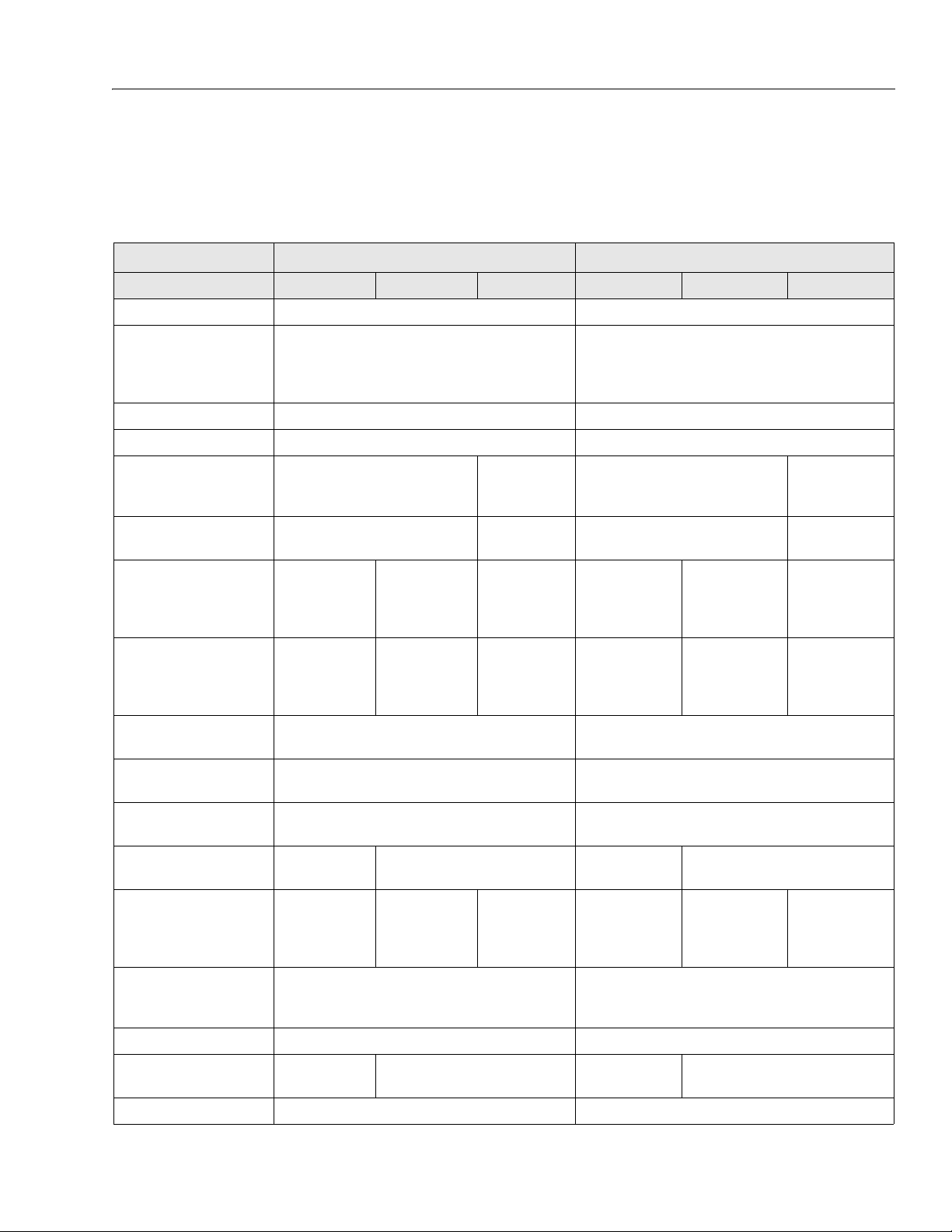
Table 1-1. Operating Specifications
Description 3369LE/M3369 4069LE/M4069
ANSI CE/AUS CSA ANSI CE/AUS CSA
Ma x . N u mb e r o f P er s on s 2 2
Max. Workload (Capacity)
Extension Only:
Max. Platform Height 33 ft (10.1m) 40 ft (12.2 m)
Max. Gradeability 35% 35%
Max. Slope (Left - Right) 5° Up to 25 ft (7.6 m)
Max. Slope (Front - Back)
Max. Slope (Left - Right)
(option al for CE machines with
37 mph (16.7 m/s) windspeed
rating only)
Max. Slope (Front - Back)
(option al forCE m achines with
37 mph (16.7 m/s) windspeed
rating only)
Max. Tire Load 3200 lbs
Max. Ground Bearing
Pressure
ANSI/CSA/Brazil: 1000 lbs (454kg)
CE/AUS: 1000 lbs (450kg)
ANSI/CSA/Brazil: 250 lbs (113kg)
CE/AUS: 250 lbs (120kg)
4° Up to 30 ft (9.1 m)
3° Up to 33 ft (10 m)
5° Up to 33 ft (10 m)
NA
NA
4° Up to 25 ft
(7.6 m)
2° Up to 33 ft
(10 m)
5° Up to 25 ft
(7.6 m)
4° Up to 33 ft
(10 m)
(1452 kg)
57 psi
2
(4 kg/cm
)
3° Up to 33 ft
3° Up to 33 ft
ANSI/CSA/Brazil: 800 lbs (363kg)
CE/AUS: 8 00 lbs (360kg)
ANSI/CSA/Brazil: 250 lbs (113kg)
CE/AUS: 2 50 lbs (120kg)
5° Up to 30 ft (9.1 m)
(10 m)
(10 m)
NA NA NA NA
NA NA NA NA
4° Up to 36 ft (11 m)
3° Up to 40 ft (12.2 m)
5° Up to 40 ft (12.2 m)
3700 lbs
(1680 kg)
61 psi
(4.3 kg/cm2)
3° Up to 40 ft
(12.2 m)
3° Up to 40 ft
(12.2 m)
Max. Allowable Wind Speed
(Standard rating)
Maximum Horizontal Manual
Side Force
Max. Allowable Wind Speed
(16.7 m/s machines only)
(Optional rating for CE Specification only)
Turning Radius:
In s id e
Ou t si d e
Wheelbase 91.5 in (2.3m) 91.5 in (2.3 m)
Gross Machine Weight
(Approximate)
Maximum Drive Speed 3 mph (4.8 kmh) 3 mph (4.8 kmh)
3121639 – JLG Lift – 1-1
667 N
(150 lb force))
NA
9,760 lbs
(4,427 kg)
28 mph
(12.5 m/s)
16.7m/s
(37 mph)
7.5 ft (2.3 m)
16 ft (4.9 m)
400 N
(90 lb force)
10,060 lbs
(4563 kg)
28 mph
(12.5 m/s)
534 N
(120 lb force)
NA NA NA NA
7.5 ft (2.3 m)
16 ft (4.9 m)
10,560 lbs
(4,790 kg)
400N
(90 lb force)
11,500 lbs
(5216.3 kg)
SECTION 1 - SPECIFICATIONS
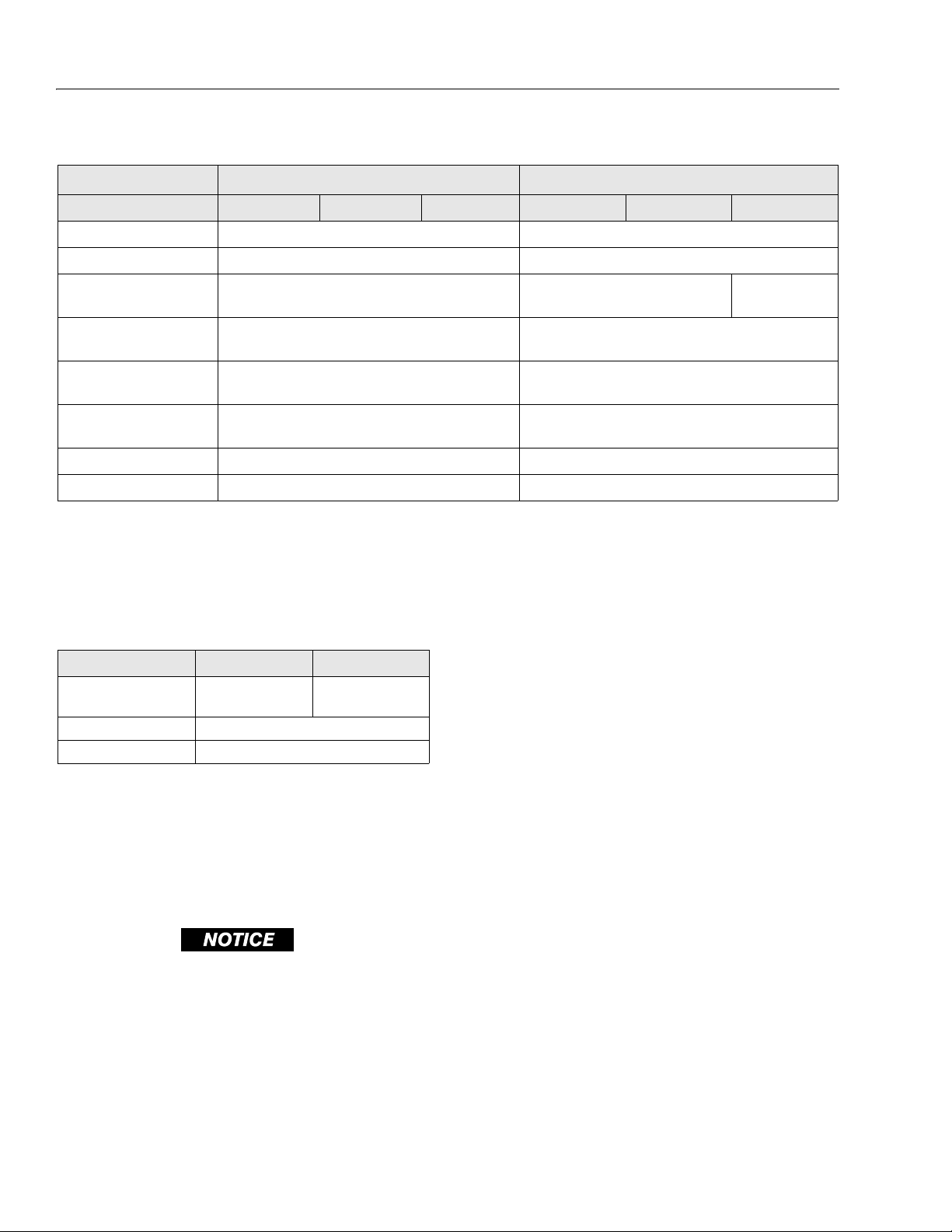
Table 1-1. Operating Specifications
Description 3369LE/M3369 4069LE/M4069
ANSI CE AUS ANSI CE AUS
Drive Speed - (reduced) 16 - 24 sec/50 ft (15 m) 16 - 24 sec/50 ft (15 m)
Drive Speed - (high) 10.6 - 12 sec/50 ft (15 m) 10.6 - 12 sec/50 ft (15 m)
Drive Speed - (creep)
(AUS Full drive height model)
Platform Lift Up Speed
(platform empty)
Platform Lowering Speed (platform empty)
Max Operating Hydraulic Pressure
NA NA
36 - 40 sec 52 - 60 sec
43 - 48 sec 49 - 51 sec
3000 psi (207 bar) 3000 psi (207 bar)
142 -146 sec/25 ft
(7.6 m)
Electrical System Voltage 48 volt 48 volt
Ground Clearance 8 in (20 cm) 8 in (20 cm)
NOTE: If function speeds are slow on a fully charged machine a clogged hydraulic filter may be indicated. Change filter.
1.2 COMPONENT DATA
Dimensional Data
Table 1-2. Dimensional Data
DELTA Q BATTERY CHARGER TO OPTIMIZE BATTERY LIFE AND
MACHINE CYCLE TIMES. THE USE OF NON APPROVED BATTERIES IN YOUR JLG EQUIPMENT MAY RESULT IN PERFORMANCE
ISSUES OR BATTERY CHARGER FAULT CODES. JLG ASSUMES
NO RESPONSIBILITY FOR SERVICE OR PERFORMANCE ISSUES
ARISING FROM THE USE OF NON APPROVED BATTERIES.
3369LE/M3369 4069LE/M4069
Transport Height (rails
down)
76.5 in (1.9 m) 79 in (2 m)
Machine Length 121 in (3.1 m)
Machine Width 69 in (1.75 m)
Drive System
Drive Motor - 48 VDC, 11.8 H.P. peak 5.5 H.P. continuous,
rotation - reversible
Drive Brake - 24 VDC, spring-applied, hydraulically
released
Steer System
Battery Charger
Input 220 VAC, 50 HZ Input, (110 VAC,60 HZ)
Output, 48 VDC @ 23 Amp
Batteries
6 Volt, 370 Amp-hour - Quantity (8) - MAC Charger
Tires - IN240/55-17.5 FF
IN240/55-17.5 FF non marking
27.2/10.5LL-15.0 FF TURF - SLR - 4020 lb.@42 PSI
Toe-In - 1/4 inch (6.4 mm) overall
Hydraulic Pump/Electric Motor Assembly
Pump Output - 3.86 gpm (14.6 lpm) @ 2175 psi (150 bar)
JLG MACHINES EQUIPPED WITH DELTA Q BATTERY CHARGERS
ARE DESIGNED FOR THE BEST PERFORMANCE WITH OEM FACTORY APPROVED BATTERIES.
APPROVED JLG REPLACEMENT BATTERIES ARE AVAILABLE
THROUGH JLG' S AFTERMARKET PARTS DISTRIBUTION CENTERS OR JLG' S AFTERMARKET PROGRAMS. FOR ASSISTANCE
WITH PROPER BATTERY REPLACEMENT, PLEASE CONTACT
YOUR LOCAL JLG SUPPORT OFFICE.
BATTERIES APPROVED BY JLG HAVE BEEN TESTED FOR COMPATIBILITY WITH THE ALGORITHM PROGRAMMING OF THE
1-2 – JLG Lift – 3121639
Tires
SECTION 1 - SPECIFICATIONS
Table 1-3. Tire Specifications
Size 240/55 D17.5 R4 Tread
(Fill tire with high durometer polyurethane at 90 psi )
Load Rating
7960 lbs @ 95 psi
(3611kg @ 655kPa)
7730 lbs @ 90 psi
(3506kg @ 621 kPa)
Ply Rating
Wheel Nut
To rq ue
12 Ply 10 Ply 6 Ply 10 Ply
Engine (Generator)
Table 1-4. Engine Specifications (Generator - If
Equipped)
TYPE
Displacement 16.85 cu. in
Bore x Stroke 2.83 in x 2.68 in (72mm x 68mm)
Number of cylinders 1
Horsepower 5.6HP/3600 rpm (4.5 kw/3600rpm)
Fuel Type Diesel (SAE No. 2-D)
Glow Plug Preheater on @ 40° F (5° C)
Weight 38 lb. (17.24 kg)
Air Cleaner Paper Element Type
Air Cooled, 4 Cycle, Kubota Diesel
OC60-D (T4F)
.
(0.276L)
IN240/55-17.5 FF 27.2/10.5-15 FF Turf
8550 lbs @ 105 psi
(3878kg @ 724kPa)
7960 lbs @ 95 psi
(3611kg @ 655kPa)
7730 lbs @ 90 psi
4019 lbs @ 42 psi
(1823kg @ 290 kPa)
2180 lbs @ 32 psi
(989kg @ 221 kPa)
(3506kg @ 621 kPa)
170 ft lbs
(230 Nm)
IN240/55-17.5
Non Marking
8550 lbs @ 105 psi
(3878kg @ 724kPa)
7960 lbs @ 95 psi
(3611kg @ 655kPa)
7730 lbs @ 90 psi
(3506kg @ 621 kPa)
Table 1-5. Engine Battery Specifications
BCI GROUP SIZE 51R - 675
Cranking Performance 550 Amps @ 32° F (0° C)
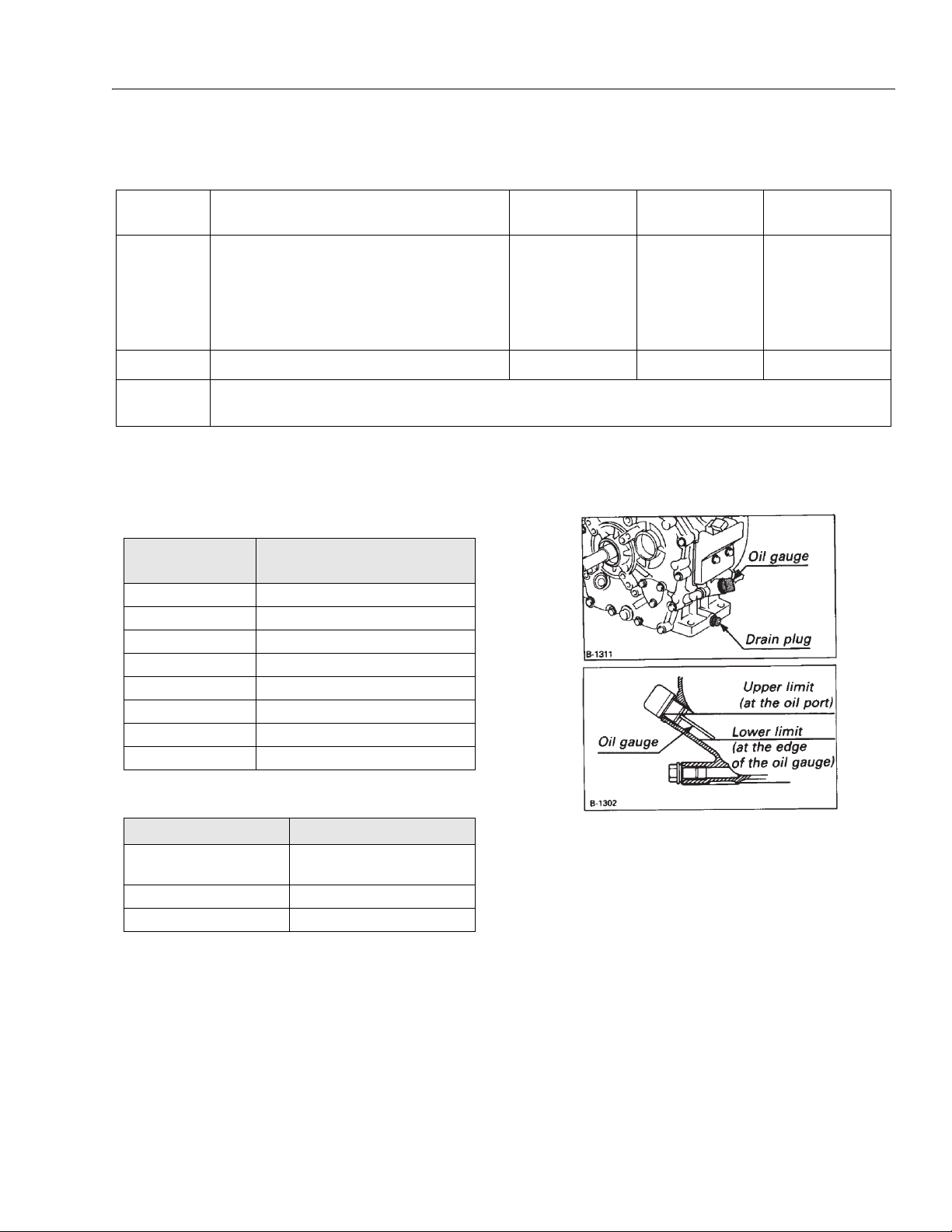
Kubota OC60-D Engine - Oil Dip Stick and Drain Location
450 Amps @ 0° F (-18° C)
Reserve Capacity 80 minutes @ 80° F(27° C)
Weight 29 lb. (13.15 kg)
3121639 – JLG Lift – 1-3
SECTION 1 - SPECIFICATIONS
1.3 CAPACITIES
Table 1-6. Capacities
Description 3369LE/M3369 4069LE/M4069
Hydraulic Tank
Hydraulic System approx. 8.5 gal (32.1 liters)
8.25 gal (31.2 liters)
5.4 gal (20.4 liters) @ full mark
Fuel Tank - (M Models only) Approx. 0.9 gal (3.3 l)
Generator Crankcase 1.37 qts(1.3 l)
1.4 PRESSURE SETTINGS
Table 1-7. Pressure Settings
Description 3369LE/M3369 4069LE/M4069
Main Relief (±50 psi)
Steer Relief
Lift Relief
2600 psi
(179 bar)
3000 psi
(207 bar)
2500 psi
(172 bar)
2800 psi
(193 bar)
1.5 TORQUE SPECIFICATIONS
Table 1-8. Torque Specifications
DESCRIPTION
To rq u e H ub
Wheel Nuts
Fixed Axle Bolts
Drive Motor
Pump Motor
Te rm ina ls
NOTE: When maintenance becomes necessary or a fas-
tener has loosened, refer to Section 1.11, Torque
Charts to determine proper torque value.
TORQUE VALUE
(DRY)
240 ft lbs
(336 Nm)
170 ft lbs
(238 Nm)
220 ft lbs
(308 Nm)
35 ft lbs
(49 Nm)
12-14 ft lbs
(14-19 Nm)
INTERVAL HOURS
500
50
500
N/A
N/A
1.6 CYLINDER SPECIFICATIONS
Table 1-9. Cylinder Specifications
DESCRIPTION BORE STROKE ROD DIA.
Lift Cylinder
(M3369/3369LE)
Upper Lift Cylinder
(M4069/4069LE)
Lower Lift Cylinder
(M4069/4069LE)
Steer Cylinder
4.00 in
(10.16 cm)
3.00 in
(7.62 cm)
4.00 in
(10.16 cm)
2.00 in
(5.08 cm)
63.69 in
(161.77 cm)
58.13 in
(147.65 cm)
58.13 in
(147.65 cm)
6.5 in
(16.51 cm)
1.7 MAJOR COMPONENT WEIGHTS
Table 1-10. Major Component Weights
Description 3369LE/M3369 4069LE/M4069
Platform 780 lbs (354 kg)
Platform Extension 360 lbs (163 kg)
Arm Assembly
(Includes Lift Cylinders)
Chassis (Includes Battery Box
and Foam filled Tires)
Foam Filled Tire and Wheel
Assembly (each)
3200 lbs
(1451 kg)
5420 lbs
(2458 kg)
180 lb. (81.6 kg)
(1769 kg)
(2502 kg)
1.8 CRITICAL STABILITY WEIGHTS
Table 1-11. Critical Stability Weights
Description 3369LE/M3369 4069LE/M4069
Platform 780 lbs (354 kg)
Platform Extension 360 lbs (163 kg)
Foam Filled Tires 207 lbs (94 kg)
Battery (Each) 122 lbs (55 kg)
2.75 in
(6.98 cm)
2.75 in
(6.98 cm)
2.25 in
(5.71 cm)
1.125 in
(2.86 cm)
3900 lbs
5517 lbs
1-4 – JLG Lift – 3121639
SECTION 1 - SPECIFICATIONS
1.9 LUBRICATION
Table 1-12. Hydraulic Oil
Hydraulic System Operating
Temp era t ure Rang e
0° F to 23° F (-18°C to -5°C) 10W
0° F to 210° F (-18°C to +99°C) 10W-20, 10W- 0
50° F to 210° F (+10°C to +99°C) 20W-20
NOTE: Hydraulic oils must have anti-wear qualities at least
to API Service Classification GL-3, and sufficient
chemical stability for mobile hydraulic system service. JLG Industries recommends Mobil DTE 11M
hydraulic oil, which has an SAE viscosity index of
140.
Aside from JLG recommendations, it is not advisable
to mix oils of different brands or types, as they may
not contain the same required additives or be of
comparable viscosities.
SAE Viscosity Grade
Lubrication Specifications
Table 1-13. Lubrication Specifications
KEY SPECIFICATIONS
EPGL
HO
LL Synthetic Lithium Lubricant, Gredag 741 Grease.
Extreme Pressure Gear Lube (oil) meeting API service
c la ss if ic at io n GL-5 or MI L-S pe c MI L-L- 21 05
Hydraulic Oil. API service classification Gl-3, BP Energol SHS46.
NOTE: Refer to Lubrication Chart - Table 1-15 for specific
lubrication procedures.
Table 1-14. Mobil DTE 11M Specs
ISO Viscosity Grade #15
Gravity API 31.9
Pour Point, Max -40°F (-40°C)
Flash Point, Min. 330°F (166°C)
Viscosity
at 40° C 15 cSt
at 100° C 4.1 cSt
at 100° F 80 SUS
at 210° F 43 SUS
cp at -30° F 3.200
Viscosity Index 140
* MPG may be substituted for these lubricants, if
necessary, but service intervals will be reduced.
3121639 – JLG Lift – 1-5
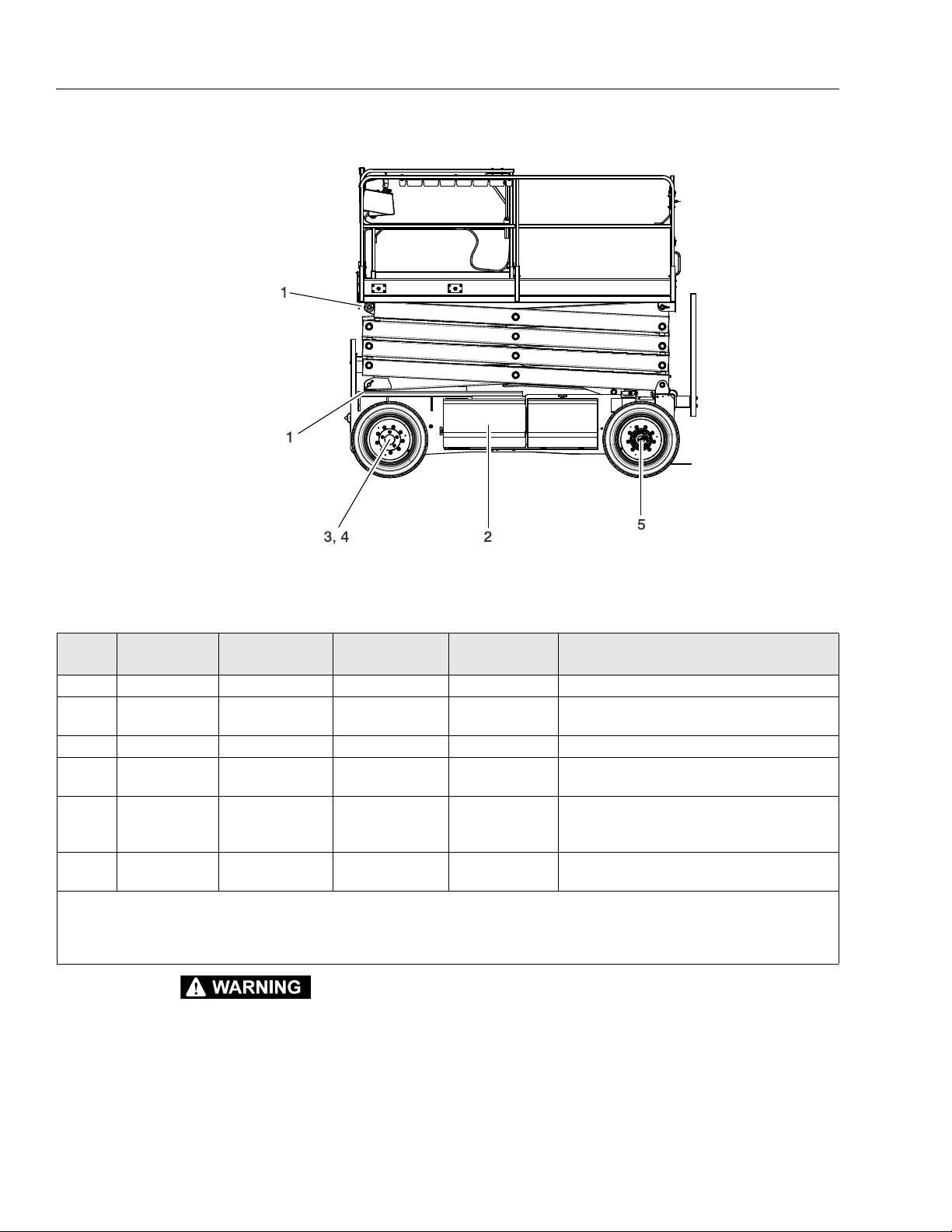
SECTION 1 - SPECIFICATIONS
Figure 1-1. Lubrication Chart
Note:
500 Hrs. = 3 months
1000 Hrs. = 6 months
2000 Hrs. = 1 year
4000 Hrs. = 2 years
Table 1-15. Lubrication Chart
INDEX
NUMBER
COMPONENT
NO/TYPE LUBE
POINTS
LUBE/METHOD
INTERVAL
HOURS
1 Sliding Wear Pads 8 Wear Pads MPG/Brush 50 --
2 Hydraulic Oil Fill Level/Drain Plug
HO - Check HO Level
HO - Change HO
10/500
Check oil every 10 hours of operation
Change oil after every 1000 hours of operation
3 Wheel Bearings Front Wheels MPG - Repack 1200 --
Spindles/Bushing
4
5 Wheel Drive Hub Fill Pl ug/Half Full EPGL 1200
(not shown)
N/A LL
At Spindle Bushing
Replacement
Change after first 150 hours of operation then every
6
KEY TO LUBRICANTS:
*High Pressure
Filter (not shown)
N/A
Replaceable
Element
50/250
Replace filter element after first 5 0 hours of operation
HO - Hydraulic Oil - Mobil DTE - 11M
EPGL - Extreme Pressure Gear Lube
MPG - Multi Purpose Grease
NOTE: Recommended lubricating intervals are based on
machine operations under normal conditions. For
TO AVOID PERSONAL INJURY, USE SAFETY PROP FOR ALL
MAINTENANCE REQUIRING PLATFORM TO BE ELEVATED
machines used in multi-shift operations and/or
exposed to hostile environments or conditions, lubricating frequencies must be increased accordingly.
NOTE: Be sure to lubricate like items on each side of the
machine.
*The high pressure filter is located in the main control valve. See figure title control valve in section 2.
COMMENTS
--
Check oil level at side plug daily.
1000 hours thereafter
and every 1000 hours thereafter.
1-6 – JLG Lift – 3121639
SECTION 1 - SPECIFICATIONS
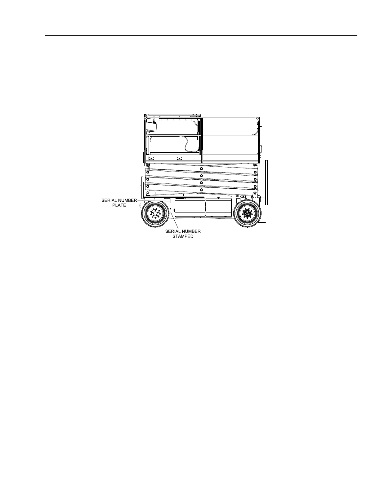
Figure 1-2. Serial Number Location
1.10 SERIAL NUMBER LOCATIONS
For machine identification, a serial number plate is affixed to the left front of the frame. If the serial number plate is damaged
or missing, the machine serial number is stamped on the left front of the machine frame.
3121639 – JLG Lift – 1-7
SECTION 1 - SPECIFICATIONS
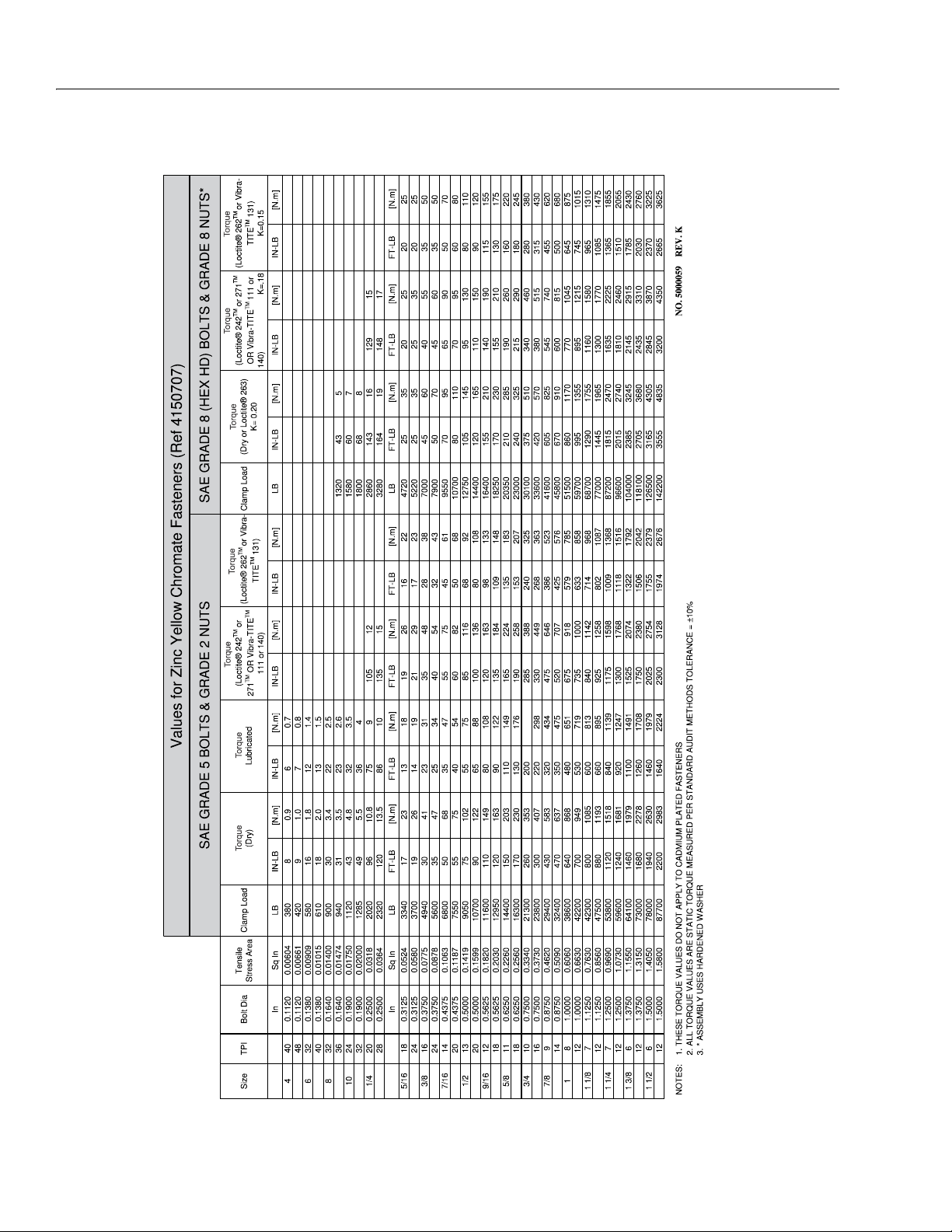
1.11 TORQUE CHARTS
Figure 1-3. Torque Chart - Sheet 1 of 5 - (SAE Fasteners)
1-8 – JLG Lift – 3121639
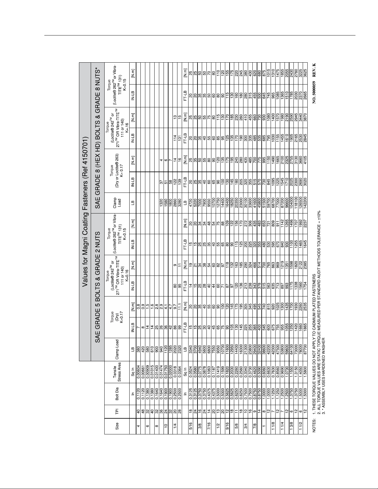
SECTION 1 - SPECIFICATIONS
Figure 1-4. Torque Chart - Sheet 2 of 5 - (SAE Fasteners)
3121639 – JLG Lift – 1-9
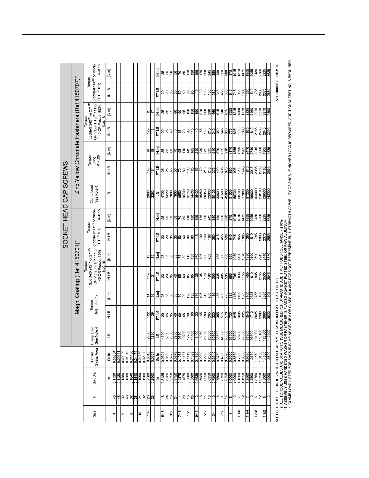
SECTION 1 - SPECIFICATIONS
Figure 1-5. Torque Chart - Sheet 3 of 5 - (SAE Fasteners)
1-10 – JLG Lift – 3121639
SECTION 1 - SPECIFICATIONS
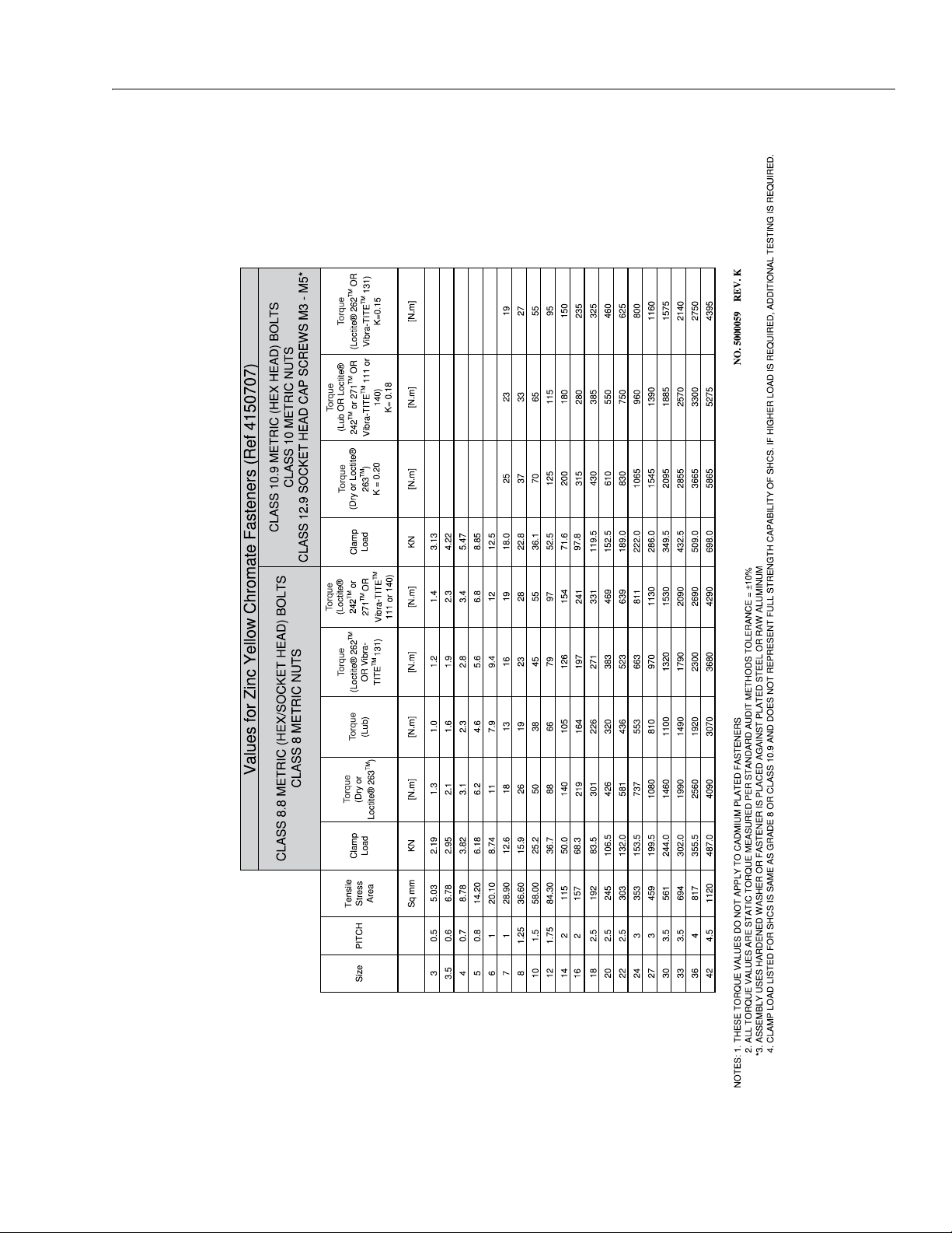
Figure 1-6. Torque Chart - Sheet 4 of 5 - (METRIC Fasteners)
3121639 – JLG Lift – 1-11
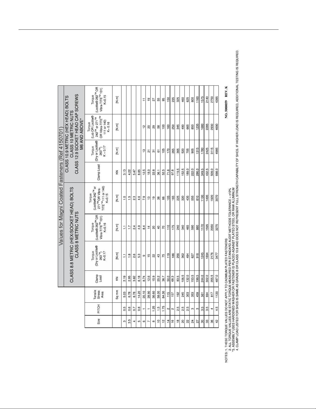
SECTION 1 - SPECIFICATIONS
Figure 1-7. Torque Chart - Sheet 5 of 5 - (METRIC Fasteners)
1-12 – JLG Lift – 3121639

SECTION 2. GENERAL
SECTION 2 - GENERAL
2.1 MACHINE PREPARATION, INSPECTION,
AND MAINTENANCE
General
This section provides the necessary information needed
by those personnel that are responsible to place the
machine in operation readiness and maintain its safe
operating condition. For maximum service life and safe
operation, ensure that all the necessary inspections and
maintenance have been completed before placing the
machine into service.
Preparation, Inspection, and Maintenance
It is important to establish and conform to a comprehensive inspection and preventive maintenance program.
The following table outlines the periodic machine inspections and maintenance recommended by JLG Industries,
Inc. Consult your national, regional, or local regulations
for further requirements for aerial work platforms. The frequency of inspections and maintenance must be
increased as environment, severity and frequency of
usage requires.
Pre-Start Inspection
It is the User’s or Operator’s primary responsibility to perform a Pre-Start Inspection of the machine prior to use
daily or at each change of operator. Reference the Operator’s and Safety Manual for completion procedures for the
Pre-Start Inspection. The Operator and Safety Manual
must be read in its entirety and understood prior to performing the Pre-Start Inspection.
Pre-Delivery Inspection and Frequent
Inspection
The Pre-Delivery Inspection and Frequent Inspection shall
be performed by a qualified JLG equipment mechanic.
JLG Industries, Inc. recognizes a qualified JLG equipment
mechanic as a person who, by possession of a recognized degree, certificate, extensive knowledge, training, or
experience, has successfully demonstrated the ability and
proficiency to service, repair, and maintain the subject
JLG product model.
The Pre-Delivery Inspection and Frequent Inspection procedures are performed in the same manner, but at different times. The Pre-Delivery Inspection shall be performed
prior to each sale, lease, or rental delivery. The Frequent
Inspection shall be accomplished for each machine in service for 3 months or 150 hours (whichever comes first);
out of service for a period of more than 3 months; or when
purchased used. The frequency of this inspection must be
increased as environment, severity and frequency of
usage requires.
Reference the JLG Pre-Delivery and Frequent Inspection
Form and the Inspection and Preventative Maintenance
Schedule for items requiring inspection during the performance of these inspections. Reference the appropriate
areas of this manual for servicing and maintenance procedures.
Annual Machine Inspection
JLG recommends that an annual machine inspection be
performed by a Factory-Certified Service Technician on an
annual basis, no later than thirteen (13) months from the
date of the prior Annual Machine Inspection. JLG Industries, Inc. recognizes a Factory-Trained Service Technician
as a person who has successfully completed the JLG Service Training School for the subject JLG product model.
Reference the machine Service and Maintenance Manual
and appropriate JLG inspection form for performance of
this inspection.
Reference the JLG Annual Machine Inspection Form and
the Inspection and Preventative Maintenance Schedule for
items requiring inspection during the performance of this
inspection. Reference the appropriate areas of this manual for servicing and maintenance procedures.
For the purpose of receiving safety-related bulletins, it is
important that JLG Industries, Inc. has updated ownership
information for each machine. When performing each
Annual Machine Inspection, notify JLG Industries, Inc. of
the current machine ownership.
Preventative Maintenance
In conjunction with the specified inspections, maintenance shall be performed by a qualified JLG equipment
mechanic. JLG Industries, Inc. recognizes a qualified JLG
equipment mechanic as a person who, by possession of a
recognized degree, certificate, extensive knowledge, training, or experience, has successfully demonstrated the
ability and proficiency to service, repair, and maintain the
subject JLG product model.
Reference the Preventative Maintenance Schedule and
the appropriate areas of this manual for servicing and
maintenance procedures. The frequency of service and
maintenance must be increased as environment, severity
and frequency of usage requires.
3121639 – JLG Lift – 2-1
SECTION 2 - GENERAL
Table 2-1. Inspection and Maintenance
Typ e Frequency
Pre-Start Inspection
Pre-Delivery
Inspection
Frequent Inspection
Annual Machine
Inspection
Preventative
Maintenance
Prior to use each day; or
At each Operator change.
Prior to each sale, lease, or
rental delivery.
In service for 3 months or 150 hours,
whichever comes first; or
Out of service for a period of more than 3
months; or
Purchased used.
Annually, no later than 13 months from the
date of the prior inspection.
At intervals as specified in the Service and
Maintenance Manual.
2.2 SERVICE AND GUIDELINES
General
The following information is provided to assist you in the
use and application of servicing and maintenance procedures contained in this book.
Safety and Workmanship
Your safety, and that of others, is the first consideration
when engaging in the maintenance of equipment. Always
be conscious of weight. Never attempt to move heavy
parts without the aid of a mechanical device. Do not allow
heavy objects to rest in an unstable position. When raising
a portion of the equipment, ensure that adequate support
is provided.
Cleanliness
Primary
Responsibility
User or Operator User or Operator Operator and Safety Manual
Owner, Dealer, or User
Owner, Dealer, or User
Owner, Dealer, or User
Owner, Dealer, or User
tions have been taken to safeguard against this.
Shields, covers, seals, and filters are provided to
keep air, fuel, and oil supplies clean; however, these
items must be maintained on a scheduled basis in
order to function properly.
2. At any time when air, fuel, or oil lines are disconnected, clear adjacent areas as well as the openings
and fittings themselves. As soon as a line or component is disconnected, cap or cover all openings to
prevent entry of foreign matter.
3. Clean and inspect all parts during servicing or maintenance, and assure that all passages and openings
are unobstructed. Cover all parts to keep them
clean. Be sure all parts are clean before they are
installed. New parts should remain in their containers until they are ready to be used.
Service
Qualification
Qualified JLG
Mechanic
Qualified JLG
Mechanic
Factory-Trained
Service Technician
(recommended)
Qualified JLG
Mechanic
Reference
Service and Maintenance
Manual and applicable JLG
inspection form.
Service and Maintenance
Manual and applicable JLG
inspection form.
Service and Maintenance
Manual and applicable JLG
inspection form.
Service and Maintenance
Manual
Components Removal and Installation
IT IS GOOD PRACTICE TO AVOID PRESSURE-WASHING ELECTRICAL/ELECTRONIC COMPONENTS. IN THE EVENT PRESSURE-WASHING THE MACHINE IS NEEDED, ENSURE THE
MACHINE IS SHUT DOWN BEFORE PRESSURE-WASHING.
SHOULD PRESSURE WASHING BE UTILIZED TO WASH AREAS
CONTAINING ELECTRICAL/ELECTRONIC COMPONENTS, JLG
INDUSTRIES, INC. RECOMMENDS A MAXIMUM PRESSURE OF
750 PSI (52 BAR) AT A MINIMUM DISTANCE OF 12 INCHES (30.5
CM) AWAY FROM THESE COMPONENTS. IF ELECTRICAL/ELECTRONIC COMPONENTS ARE SPRAYED, SPRAYING MUST NOT
BE DIRECT AND BE FOR BRIEF TIME PERIODS TO AVOID HEAVY
SATURATION.
1. The most important single item in preserving the
long service life of a machine is to keep dirt and foreign materials out of the vital components. Precau-
2-2 – JLG Lift– 3121639
1. Use adjustable lifting devices, whenever possible, if
mechanical assistance is required. All slings (chains,
cables, etc.) should be parallel to each other and as
near perpendicular as possible to top of part being
lifted.
2. Should it be necessary to remove a component on
an angle, keep in mind that the capacity of an eyebolt or similar bracket lessens, as the angle between
the supporting structure and the component
becomes less than 90°.
3. If a part resists removal, check to see whether all
nuts, bolts, cables, brackets, wiring, etc., have been
removed and that no adjacent parts are interfering.

SECTION 2 - GENERAL
Component Disassembly and Reassembly
When disassembling or reassembling a component, complete the procedural steps in sequence. Do not partially
disassemble or assemble one part, then start on another.
Always recheck your work to assure that nothing has been
overlooked. Do not make any adjustments, other than
those recommended, without obtaining proper approval.
Pressure-Fit Parts
When assembling pressure-fit parts, use an anti-seize or
molybdenum disulfide base compound to lubricate the
mating surface.
Bearings
1. When a bearing is removed, cover it to keep out dirt
and abrasives. Clean bearings in nonflammable
cleaning solvent and allow to drip dry. Compressed
air can be used but do not spin the bearing.
2. Discard bearings if the races and balls (or rollers)
are pitted, scored, or burned.
3. If bearing is found to be serviceable, apply a light
coat of oil and wrap it in clean (waxed) paper. Do not
unwrap reusable or new bearings until they are
ready to install.
4. Lubricate new or used serviceable bearings before
installation. When pressing a bearing into a retainer
or bore, apply pressure to the outer race. If the bearing is to be installed on a shaft, apply pressure to the
inner race.
dance with recommended shop practices. (See
Torque Chart Section 1.)
Hydraulic Lines and Electrical Wiring
Clearly mark or tag hydraulic lines and electrical wiring, as
well as their receptacles, when disconnecting or removing
them from the unit. This will assure that they are correctly
reinstalled.
Hydraulic System
1. Keep the system clean. If evidence of metal or rubber particles are found in the hydraulic system, drain
and flush the entire system.
2. Disassemble and reassemble parts on clean work
surface. Clean all metal parts with non-flammable
cleaning solvent. Lubricate components, as
required, to aid assembly.
Lubrication
Service applicable components with the amount, type,
and grade of lubricant recommended in this manual, at
the specified intervals. When recommended lubricants are
not available, consult your local supplier for an equivalent
that meets or exceeds the specifications listed.
Battery
Clean battery, using a non-metallic brush and a solution of
baking soda and water. Rinse with clean water. After
cleaning, thoroughly dry battery and coat terminals with
an anti corrosion compound.
Gaskets
Check that holes in gaskets align with openings in the
mating parts. If it becomes necessary to hand-fabricate a
gasket, use gasket material or stock of equivalent material
and thickness. Be sure to cut holes in the right location, as
blank gaskets can cause serious system damage.
Bolt Usage and Torque Application
1. Self locking fasteners, such as nylon insert and
thread deforming locknuts, are not intended to be
reinstalled after removal. Always use new replacement hardware when installing locking fasteners.
2. Use bolts of proper length. A bolt which is too long
will bottom before the head is tight against its related
part. If a bolt is too short, there will not be enough
thread area to engage and hold the part properly.
When replacing bolts, use only those having the
same specifications of the original, or one which is
equivalent.
3. Unless specific torque requirements are given within
the text, standard torque values should be used on
heat-treated bolts, studs, and steel nuts, in accor-
Lubrication and Servicing
Components and assemblies requiring lubrication and
servicing are shown in the Lubrication Chart in Section 1.
3121639 – JLG Lift – 2-3

SECTION 2 - GENERAL
2.3 LUBRICATION AND INFORMATION
Hydraulic System
1. The primary enemy of a hydraulic system is contamination. Contaminants enter the system by various
means, e.g., using inadequate hydraulic oil, allowing
moisture, grease, filings, sealing components, sand,
etc., to enter when performing maintenance, or by
permitting the pump to cavitate due to insufficient
system warm-up or leaks in the pump supply (suction) lines.
2. The design and manufacturing tolerances of the
component working parts are very close, therefore,
even the smallest amount of dirt or foreign matter
entering a system can cause wear or damage to the
components and generally results in faulty operation. Every precaution must be taken to keep
hydraulic oil clean, including reserve oil in storage.
Hydraulic system filters should be checked,
cleaned, and/or replaced as necessary, at the specified intervals required in the Lubrication Chart in
Section 1. Always examine filters for evidence of
metal particles.
3. Cloudy oils indicate a high moisture content which
permits organic growth, resulting in oxidation or corrosion. If this condition occurs, the system must be
drained, flushed, and refilled with clean oil.
4. It is not advisable to mix oils of different brands or
types, as they may not contain the same required
additives or be of comparable viscosities. Good
grade mineral oils, with viscosities suited to the
ambient temperatures in which the machine is operating, are recommended for use.
NOTE: Metal particles may appear in the oil or filters of new
machines due to the wear-in of meshing components.
Hydraulic Oil
1. Refer to Section 1 for recommendations for viscosity
ranges.
This will allow start up at temperatures down to -20°
F (-29° C). However, use of this oil will give poor performance at temperatures above 120°F (49°C). Systems using DTE 13 oil should not be operated at
temperatures above 200°F (94°C) under any condition.
Changing Hydraulic Oil
1. Use of any of the recommended hydraulic oils eliminates the need for changing the oil on a regular
basis. However, filter elements must be changed
after the first 50 hours of operation and every 300
hours thereafter. If it is necessary to change the oil,
use only those oils meeting or exceeding the specifications appearing in this manual. If unable to obtain
the same type of oil supplied with the machine, consult local supplier for assistance in selecting the
proper equivalent. Avoid mixing petroleum and synthetic base oils. JLG Industries recommends changing the hydraulic oil annually.
2. Use every precaution to keep the hydraulic oil clean.
If the oil must be poured from the original container
into another, be sure to clean all possible contaminants from the service container. Always clean the
mesh element of the filter and replace the cartridge
any time the system oil is changed.
3. While the unit is shut down, a good preventive maintenance measure is to make a thorough inspection
of all hydraulic components, lines, fittings, etc., as
well as a functional check of each system, before
placing the machine back in service.
Lubrication Specifications
Specified lubricants, as recommended by the component
manufacturers, are always the best choice, however,
multi-purpose greases usually have the qualities which
meet a variety of single purpose grease requirements.
Should any question arise, regarding the use of greases in
maintenance stock, consult your local supplier for evaluation. Refer to Section 1 for an explanation of the lubricant
key designations appearing in the Lubrication Chart.
2. JLG recommends Mobilfluid 424 hydraulic oil, which
has an SAE viscosity of 10W-30 and a viscosity
index of 152.
NOTE: Start-up of hydraulic system with oil temperatures
below -15°F (-26°C) is not recommended. If it is necessary to start the system in a sub-zero environment, it will be necessary to heat the oil with a low
density, 100VAC heater to a minimum temperature of
-15°F (-26°C).
3. The only exception to the above is to drain and fill
the system with Mobil DTE 13 oil or its equivalent.
2-4 – JLG Lift– 3121639
SECTION 2 - GENERAL
2.4 CYLINDER DRIFT TEST
Maximum acceptable cylinder drift is to be measured
using the following methods.
Platform Drift
Measure the drift of the platform to the ground. Fully elevate the platform. Maximum allowable drift is 2 in. (5 cm)
in 10 minutes. If the machine does not pass this test, proceed with the following.
Cylinder Drift
Table 2-2. Cylinder Drift
Cylinder Bore Diameter
inches mm inches mm
3 76.2 0.026 0.66
3.5 89 0.019 0.48
4 101.6 0.015 0.38
5 127 0.009 0.22
6 152.4 0.006 0.15
7 177.8 0.005 0.13
Drift is to be measured at the cylinder rod with a calibrated
dial indicator. The cylinder oil must be at ambient temperature and temperature stabilized.
The cylinder must have the normal load, which is the normal platform load applied.
If the cylinder passes this test, it is acceptable.
NOTE: This information is based on 6 drops per minute cyl-
inder leakage.
Max. Acceptable Drift
in 10 Minutes
2.5 PINS AND COMPOSITE BEARING REPAIR
GUIDELINES
Filament wound bearings.
1. Pinned joints should be disassembled and
inspected if the following occurs:
a. Excessive sloppiness in joints.
b. Noise originating from the joint during operation.
2. Filament wound bearings should be replaced if any
of the following is observed:
a. Frayed or separated fibers on the liner surface.
b. Cracked or damaged liner backing.
c. Bearings that have moved or spun in their hous-
ing.
d. Debris embedded in liner surface.
3. Pins should be replaced if any of the following is
observed (pin should be properly cleaned prior to
inspection):
a. Detectable wear in the bearing area.
b. Flaking, pealing, scoring, or scratches on the pin
surface.
c. Rusting of the pin in the bearing area.
4. Re-assembly of pinned joints using filament wound
bearings.
a. Housing should be blown out to remove all dirt
and debris...bearings and bearing housings
must be free of all contamination.
b. Bearing / pins should be cleaned with a solvent
to remove all grease and oil...filament wound
bearing are a dry joint and should not be lubricated.
c. Pins should be inspected to ensure it is free of
burrs, nicks, and scratches which would damage the bearing during installation and operation.
3121639 – JLG Lift – 2-5

SECTION 2 - GENERAL
2.6 PREVENTIVE MAINTENANCE AND
INSPECTION SCHEDULE
The preventive maintenance and inspection checks are
listed and defined in Table 2-3, Preventive Maintenance
and Inspection Schedule. This table is divided into two
basic parts, the “AREA” to be inspected, and the “INTERVAL” at which the inspection is to take place. Under the
“AREA” of the table, the various systems along with components that make up that system are listed. The “INTERVAL” portion of the table is divided into five columns
representing the various inspection time periods. The
numbers listed within the interval column represent the
applicable inspection code for which that component is to
be checked.
The checks and services listed in this schedule are not
intended to replace any local or regional regulations that
may pertain to this type of equipment nor should the lists
be considered as all inclusive. Variances in interval times
may occur due to climate and/or conditions and depending on the location and use of the machine.
JLG Industries requires that a complete annual inspection
be performed in accordance with the “Annual Machine
Inspection Report” form. Forms are supplied with each
new machine and are also available from JLG Customer
Service. Forms must be completed and returned to JLG
Industries.
JLG INDUSTRIES REQUIRES THAT A COMPLETE ANNUAL
INSPECTION BE PERFORMED IN ACCORDANCE WITH THE
“ANNUAL MACHINE INSPECTION REPORT” FORM.
The inspection and maintenance code numbers for Table
2-3, Preventive Maintenance and Inspection Schedule, are
as follows:
1. Check for proper and secure installation.
2. Check for visible damage and legibility.
3. Check for proper fluid level.
4. Check for any structural damage; cracked or broken
welds; bent or warped surfaces.
5. Check for leakage.
6. Check for presence of excessive dirt or foreign
material.
7. Check for proper operation and freedom of movement.
8. Check for excessive wear or damage.
9. Check for proper tightness and adjustment.
10. Drain, clean and refill.
11. Check for proper operation while unit power is on.
12. Check for proper lubrication.
13. Check for evidence of scratches, nicks or rust and
for straightness of rod.
14. Check for condition of element; replace as necessary.
15. Check for proper inflation.
16. Clean or replace suction screen.
NOTE: This machine requires periodic safety and mainte-
nance inspections by a JLG Dealer. A decal located
on the frame affords a place to record (stamp)
inspection dates. Notify dealer if inspection is overdue.
2-6 – JLG Lift– 3121639
 Loading...