


JLG 45HA Parts Manual

Illustrated Parts Manual
Model
45HA
P/N
3120626
March 15, 2012


REVISION LOG
May 1988 - Original Issue Of Manual
January 1990 - Revised
January 1994 - Revised
August 1994 - Change 1
March 1995 - Change 2
July 1997 - Revised
March 15, 2001 - Revised (Edited 0010415 to Revision 19)
August 18, 2005 - Revised
June 10, 2009 - Revised
March 15, 2012 - Revised
3120626 A

REVISION LOG
B 3120626

TABLE OF CONTENTS
FIGURE NO. TITLE PAGE NO.
SECTION 1 - FRAME
1-1 Frame & Steering Installation - 5’-9”/1.75M 2WD Frame (Single Rod Cylinder) . . . . . . . . . . . . .1-2
1-2 Frame & Steering Installation - 6’-6”/2M 2WD Frame (Double Rod Cylinder) . . . . . . . . . . . . . . .1-6
1-3 Frame & Steering Installation - 6’-6”/2M 4WD Frame . . . . . . . . . . . . . . . . . . . . . . . . . . . . . . . . .1-10
1-4 Tire And Wheel Drive Installations . . . . . . . . . . . . . . . . . . . . . . . . . . . . . . . . . . . . . . . . . . . . . . .1-14
1-5 Drive Hub Assembly . . . . . . . . . . . . . . . . . . . . . . . . . . . . . . . . . . . . . . . . . . . . . . . . . . . . . . . . . . 1-20
1-6 Drive Hub/Brake Assembly . . . . . . . . . . . . . . . . . . . . . . . . . . . . . . . . . . . . . . . . . . . . . . . . . . . . .1-26
1-7 Drive Brake Assembly - Ausco . . . . . . . . . . . . . . . . . . . . . . . . . . . . . . . . . . . . . . . . . . . . . . . . . .1-32
1-8 Drive Brake Assembly - Mico . . . . . . . . . . . . . . . . . . . . . . . . . . . . . . . . . . . . . . . . . . . . . . . . . . .1-34
1-9 Drive Motor Assembly - 2WD. . . . . . . . . . . . . . . . . . . . . . . . . . . . . . . . . . . . . . . . . . . . . . . . . . . . 1-38
1-10 Drive Motor Assembly - 4WD. . . . . . . . . . . . . . . . . . . . . . . . . . . . . . . . . . . . . . . . . . . . . . . . . . . . 1-42
1-11 Valves Installations (Frame Mounted) . . . . . . . . . . . . . . . . . . . . . . . . . . . . . . . . . . . . . . . . . . . . .1-46
1-12 Lockout Valve Assembly . . . . . . . . . . . . . . . . . . . . . . . . . . . . . . . . . . . . . . . . . . . . . . . . . . . . . . .1-50
1-13 Tow Package Installation . . . . . . . . . . . . . . . . . . . . . . . . . . . . . . . . . . . . . . . . . . . . . . . . . . . . . . .1-52
SECTION 2 - TURNTABLE
2-1 Control Valves Installations - Stepper Valves. . . . . . . . . . . . . . . . . . . . . . . . . . . . . . . . . . . . . . . .2-2
2-2 Control Valves Installations - Vickers Valves (Kohler Gas & Electric Machines) . . . . . . . . . . . . .2-6
2-3 Control Valves Installations - Vickers Valves (Ford Gas, Deutz Diesel & Kubota Diesel) . . . . . . 2-10
2-4 Stepper Control Valves Assembly . . . . . . . . . . . . . . . . . . . . . . . . . . . . . . . . . . . . . . . . . . . . . . . .2-14
2-5 Valve Assembly - FPS (Steer) . . . . . . . . . . . . . . . . . . . . . . . . . . . . . . . . . . . . . . . . . . . . . . . . . . .2-16
2-6 Valve Assembly - 4 Stack Racine . . . . . . . . . . . . . . . . . . . . . . . . . . . . . . . . . . . . . . . . . . . . . . . .2-18
2-7 Valve Assembly - FPS . . . . . . . . . . . . . . . . . . . . . . . . . . . . . . . . . . . . . . . . . . . . . . . . . . . . . . . .2-22
2-8 Control Valve Assembly (Vickers) (Prior to October 1994) . . . . . . . . . . . . . . . . . . . . . . . . . . . . .2-24
2-9 Control Valve Assembly (Vickers) (October 1994 to Present) . . . . . . . . . . . . . . . . . . . . . . . . . .2-28
2-10 Valve Assembly - Single Stack Racine . . . . . . . . . . . . . . . . . . . . . . . . . . . . . . . . . . . . . . . . . . . .2-32
2-11 Accessory Valve Assembly (Miller) . . . . . . . . . . . . . . . . . . . . . . . . . . . . . . . . . . . . . . . . . . . . . . .2-34
2-12 Accessory Valve Assembly (Hydraforce) . . . . . . . . . . . . . . . . . . . . . . . . . . . . . . . . . . . . . . . . . . 2-36
2-13 Turntable, Bearing and Swing Drive Installation . . . . . . . . . . . . . . . . . . . . . . . . . . . . . . . . . . . . .2-38
2-14 Swing Brake Assembly . . . . . . . . . . . . . . . . . . . . . . . . . . . . . . . . . . . . . . . . . . . . . . . . . . . . . . . .2-42
2-15 Swing Motor Assembly . . . . . . . . . . . . . . . . . . . . . . . . . . . . . . . . . . . . . . . . . . . . . . . . . . . . . . . .2-44
2-16 Ford Engine Installation (With Electronic Ignition) (Prior to March 1990) . . . . . . . . . . . . . . . . . .2-46
2-17 Ford Engine Installation (With DIS) (March 1990 To Present) . . . . . . . . . . . . . . . . . . . . . . . . . . .2-52
2-18 Dual Fuel Installation (Ford with Electronic Ignition) (Prior to March 1990). . . . . . . . . . . . . . . . . 2-62
2-19 Dual Fuel Installation (Ford with DIS) (March 1990 To Present) . . . . . . . . . . . . . . . . . . . . . . . . . 2-64
2-20 Generator Installation - 110V (Ford Machines) (Optional) . . . . . . . . . . . . . . . . . . . . . . . . . . . . .2-66
2-21 Deutz Engine Installation . . . . . . . . . . . . . . . . . . . . . . . . . . . . . . . . . . . . . . . . . . . . . . . . . . . . . . . 2-70
2-22 Generator Installation - 110V (Deutz Machines) (Optional) . . . . . . . . . . . . . . . . . . . . . . . . . . . . .2-78
2-23 Pump Assembly - Barnes (Ford & Deutz Powered Machines) . . . . . . . . . . . . . . . . . . . . . . . . . .2-82
2-24 Kubota Engine Installation . . . . . . . . . . . . . . . . . . . . . . . . . . . . . . . . . . . . . . . . . . . . . . . . . . . . . .2-84
2-25 Throttle & Fuel Shut-Off Installation (Kubota Engines) . . . . . . . . . . . . . . . . . . . . . . . . . . . . . . . .2-90
2-26 Kohler Engine Installation . . . . . . . . . . . . . . . . . . . . . . . . . . . . . . . . . . . . . . . . . . . . . . . . . . . . . .2-92
2-27 Dual Fuel Installation (Kohler) . . . . . . . . . . . . . . . . . . . . . . . . . . . . . . . . . . . . . . . . . . . . . . . . . . . 2-98
2-28 Generator Installation (Kohler) (Optional) . . . . . . . . . . . . . . . . . . . . . . . . . . . . . . . . . . . . . . . . . .2-100
2-29 Electric Powered Machines Components Installation . . . . . . . . . . . . . . . . . . . . . . . . . . . . . . . . .2-104
2-30 Pump Assembly - Barnes (Kohler, Kubota & Electric Powered Machines) . . . . . . . . . . . . . . . . . 2-110
2-31 Battery Charger Assembly (Electric Powered Machines) . . . . . . . . . . . . . . . . . . . . . . . . . . . . . .2-112
2-32 Double Battery Package & Inverter Installations (Electric Machines Options). . . . . . . . . . . . . . .2-114
3120626 i

TABLE OF CONTENTS
(Continued)
FIGURE NO. TITLE PAGE NO.
2-33 Tank Installation . . . . . . . . . . . . . . . . . . . . . . . . . . . . . . . . . . . . . . . . . . . . . . . . . . . . . . . . . . . . . . 2-116
2-34 Rotary Oil Coupling Installation . . . . . . . . . . . . . . . . . . . . . . . . . . . . . . . . . . . . . . . . . . . . . . . . . . 2-122
2-35 Optional Manual Descent Installation . . . . . . . . . . . . . . . . . . . . . . . . . . . . . . . . . . . . . . . . . . . . . 2-124
2-36 Ground Control Box Installation (All Machines with Electric Boom Limit Switches Built Prior
to May 1988) . . . . . . . . . . . . . . . . . . . . . . . . . . . . . . . . . . . . . . . . . . . . . . . . . . . . . . . . . . . . .2-126
2-37 Ground Control Box Installation (Gas/Diesel Machines with Hydraulic Boom Limit Switches
Built May 1988 to March 1990 & Electric Machines with Hydraulic Boom Limit Switches
Built March 1990 to Present) . . . . . . . . . . . . . . . . . . . . . . . . . . . . . . . . . . . . . . . . . . . . . . . .2-130
2-38 Ground Control Box Installation (Gas/Diesel Machines with Hydraulic Boom Limit Switches
Built March 1990 to Present) . . . . . . . . . . . . . . . . . . . . . . . . . . . . . . . . . . . . . . . . . . . . . . . . 2-134
2-39 Tilt Indicator, Light & Alarms Installation (Turntable Mounted) . . . . . . . . . . . . . . . . . . . . . . . . . . 2-138
2-40 Hoods Installation (Gas/Diesel Machines Built Prior to March 1990 & All Electric Machines) . . 2-142
2-41 Hoods Installation (Gas/Diesel Machines Built March 1990 through 1992) . . . . . . . . . . . . . . . . 2-146
2-42 Hoods Installation (Gas/Diesel Machines Built 1993 to Present) . . . . . . . . . . . . . . . . . . . . . . . . 2-148
SECTION 3 - BOOM
3-1 Booms And Limit Switches Installation . . . . . . . . . . . . . . . . . . . . . . . . . . . . . . . . . . . . . . . . . . . .3-2
3-2 Main Boom Assembly . . . . . . . . . . . . . . . . . . . . . . . . . . . . . . . . . . . . . . . . . . . . . . . . . . . . . . . . 3-6
3-3 Tower Boom Assemblies . . . . . . . . . . . . . . . . . . . . . . . . . . . . . . . . . . . . . . . . . . . . . . . . . . . . . . . 3-10
3-4 Boom Wipers Installation . . . . . . . . . . . . . . . . . . . . . . . . . . . . . . . . . . . . . . . . . . . . . . . . . . . . . . 3-14
SECTION 4 - PLATFORMS
4-1 Standard Platform and Footswitch Installations. . . . . . . . . . . . . . . . . . . . . . . . . . . . . . . . . . . . . . 4-2
4-2 Low Mount Platform and Footswitch Installations . . . . . . . . . . . . . . . . . . . . . . . . . . . . . . . . . . . . 4-8
4-3 Fiberglass Platform . . . . . . . . . . . . . . . . . . . . . . . . . . . . . . . . . . . . . . . . . . . . . . . . . . . . . . . . . . . 4-12
4-4 Rotator Motor Assembly . . . . . . . . . . . . . . . . . . . . . . . . . . . . . . . . . . . . . . . . . . . . . . . . . . . . . . . 4-14
4-5 Console Box Assembly - PQ Controllers and Stepper Valves . . . . . . . . . . . . . . . . . . . . . . . . . . 4-16
4-6 Console Box Assembly - PQ Controllers and Vickers Valves . . . . . . . . . . . . . . . . . . . . . . . . . . . 4-20
4-7 Console Box Assembly - PQ Controllers and Vickers Valves . . . . . . . . . . . . . . . . . . . . . . . . . . . 4-24
4-8 Console Box Assembly - OEM Controllers and Vickers Valves. . . . . . . . . . . . . . . . . . . . . . . . . . 4-28
4-9 Console Box Assembly - OEM Controllers and Vickers Valves. . . . . . . . . . . . . . . . . . . . . . . . . . 4-32
4-10 Optional Common Platform Mounted Components. . . . . . . . . . . . . . . . . . . . . . . . . . . . . . . . . . . 4-36
SECTION 5 - CYLINDERS
5-1 Accumlator Assembly (Machines With Stepper Valves) . . . . . . . . . . . . . . . . . . . . . . . . . . . . . . . 5-2
5-2 Axle Lockout Cylinder Assembly . . . . . . . . . . . . . . . . . . . . . . . . . . . . . . . . . . . . . . . . . . . . . . . . . 5-4
5-3 Level Cylinder Assembly (Tower Boom) . . . . . . . . . . . . . . . . . . . . . . . . . . . . . . . . . . . . . . . . . . . 5-6
5-4 Lift Cylinder Assembly (Main Boom) . . . . . . . . . . . . . . . . . . . . . . . . . . . . . . . . . . . . . . . . . . . . . .5-8
5-5 Lift Cylinder Assembly (Tower Boom) . . . . . . . . . . . . . . . . . . . . . . . . . . . . . . . . . . . . . . . . . . . . .5-10
5-6 Platform Level Cylinder Assembly (Main Boom) (Prior to October 1992). . . . . . . . . . . . . . . . . . 5-12
5-7 Platform Level Cylinder Assembly (Main Boom) (October 1992 to Present). . . . . . . . . . . . . . . . 5-14
5-8 Steer Cylinder Assembly (2WD Double Acting Rod). . . . . . . . . . . . . . . . . . . . . . . . . . . . . . . . . . 5-16
5-9 Steer Cylinder Assembly (2WD Single Acting Rod) . . . . . . . . . . . . . . . . . . . . . . . . . . . . . . . . . . 5-18
5-10 Steer Cylinder Assembly (4WD) . . . . . . . . . . . . . . . . . . . . . . . . . . . . . . . . . . . . . . . . . . . . . . . . . 5-20
5-11 Telescope Cylinder Assembly (Main Boom) (Prior to June 1991) . . . . . . . . . . . . . . . . . . . . . . . . 5-22
5-12 Telescope Cylinder Assembly (Main Boom) (June 1991 to Present). . . . . . . . . . . . . . . . . . . . . . 5-24
5-13 Telescope Cylinder Assembly (Tower Boom) (July 1988 to Present) . . . . . . . . . . . . . . . . . . . . . 5-26
ii 3120626

TABLE OF CONTENTS
FIGURE NO. TITLE PAGE NO.
5-14 Cylinder Bellows Installation (Optional) . . . . . . . . . . . . . . . . . . . . . . . . . . . . . . . . . . . . . . . . . . . .5-28
SECTION 6 - HYDRAULICS
6-1 Axle Lockout Without Swivel Hydraulic Diagram . . . . . . . . . . . . . . . . . . . . . . . . . . . . . . . . . . . .6-2
6-2 Drive Hydraulic Diagram (2WD With Swivel & With Vickers Valves) . . . . . . . . . . . . . . . . . . . . .6-4
6-3 Drive Hydraulic Diagram (4WD With Swivel & With Vickers Valves) . . . . . . . . . . . . . . . . . . . . . .6-8
6-4 Lift & Level (Tower Boom) Hydraulic Diagram (Vickers Valves & Hydraulic Boom Limit
Switches) . . . . . . . . . . . . . . . . . . . . . . . . . . . . . . . . . . . . . . . . . . . . . . . . . . . . . . . . . . . . . . . . . .6-12
6-5 Lift & Slave (Main Boom) Hydraulic Diagram. . . . . . . . . . . . . . . . . . . . . . . . . . . . . . . . . . . . . . . .6-14
6-6 Pump Hydraulic Diagram (Vickers Valves - Ford Gas & Deutz Diesel) . . . . . . . . . . . . . . . . . . . .6-16
6-7 Pump Hydraulic Diagram (Vickers Valves - Electric Machines) . . . . . . . . . . . . . . . . . . . . . . . . .6-20
6-8 Rotation Hydraulic Diagram . . . . . . . . . . . . . . . . . . . . . . . . . . . . . . . . . . . . . . . . . . . . . . . . . . . . 6-24
6-9 Steer With Swivel Hydraulic Diagram . . . . . . . . . . . . . . . . . . . . . . . . . . . . . . . . . . . . . . . . . . . . .6-26
6-10 Swing Hydraulic Diagram (With Vickers Valves) . . . . . . . . . . . . . . . . . . . . . . . . . . . . . . . . . . . . . 6-28
6-11 Telescope (Main Boom) Hydraulic Diagram . . . . . . . . . . . . . . . . . . . . . . . . . . . . . . . . . . . . . . . .6-30
6-12 Telescope (Tower Boom) Hydraulic Diagram (Ford Gas & Deutz Diesel) . . . . . . . . . . . . . . . . . . 6-32
6-13 Telescope (Tower Boom) Hydraulic Diagram (Electric Machines) . . . . . . . . . . . . . . . . . . . . . . . .6-34
6-14 Hydraulic Diagram List. . . . . . . . . . . . . . . . . . . . . . . . . . . . . . . . . . . . . . . . . . . . . . . . . . . . . . . . .6-36
SECTION 7 - ELECTRICAL
7-1 Electrical Diagram List . . . . . . . . . . . . . . . . . . . . . . . . . . . . . . . . . . . . . . . . . . . . . . . . . . . . . . . . .7-2
7-2 Accessory Valve Wiring Diagram. . . . . . . . . . . . . . . . . . . . . . . . . . . . . . . . . . . . . . . . . . . . . . . . .7-9
7-3 Contactor Box Wiring Diagram (Electric Machines). . . . . . . . . . . . . . . . . . . . . . . . . . . . . . . . . . .7-10
7-4 Dual Fuel Wiring Diagram (Ford Dual Fuel Machines) . . . . . . . . . . . . . . . . . . . . . . . . . . . . . . . .7-11
7-5 Generator Wiring Diagram (Deutz Machines) . . . . . . . . . . . . . . . . . . . . . . . . . . . . . . . . . . . . . . .7-12
7-6 Generator Wiring Diagram (Ford Machines . . . . . . . . . . . . . . . . . . . . . . . . . . . . . . . . . . . . . . . . .7-13
7-7 Platform Wiring Diagram (Gas And Diesel Machines . . . . . . . . . . . . . . . . . . . . . . . . . . . . . . . . .7-14
7-8 Platform Wiring Diagram (Electric Machines . . . . . . . . . . . . . . . . . . . . . . . . . . . . . . . . . . . . . . . .7-15
7-9 Standard Wiring Diagram (Deutz Diesel Machines . . . . . . . . . . . . . . . . . . . . . . . . . . . . . . . . . . . 7-16
7-10 Standard Wiring Diagram (Ford Gas Machines . . . . . . . . . . . . . . . . . . . . . . . . . . . . . . . . . . . . . .7-18
7-11 Standard Wiring Diagram (Electric Machines . . . . . . . . . . . . . . . . . . . . . . . . . . . . . . . . . . . . . . .7-20
SECTION 8 - DECALS
8-1 Decals Installation (45HA Prior to August 1991) . . . . . . . . . . . . . . . . . . . . . . . . . . . . . . . . . . . . .8-2
8-2 Decal Installation (45HA August 1991 to Present). . . . . . . . . . . . . . . . . . . . . . . . . . . . . . . . . . . .8-6
SECTION 9 - RECOMMENDED SERVICE PARTS STOCK
SECTION 10 - SPECIAL OPTIONS
10-1 Miscellaneous Special Options. . . . . . . . . . . . . . . . . . . . . . . . . . . . . . . . . . . . . . . . . . . . . . . 10-1
10-2 U/L Machines Special Options . . . . . . . . . . . . . . . . . . . . . . . . . . . . . . . . . . . . . . . . . . . . . . . 10-6
10-3 440V Electric Pedestal Machines Special Options . . . . . . . . . . . . . . . . . . . . . . . . . . . . . . . . 10-7
10-4 Japanese Machine Options . . . . . . . . . . . . . . . . . . . . . . . . . . . . . . . . . . . . . . . . . . . . . . . . . 10-8
3120626 iii

TABLE OF CONTENTS
FIGURE NO. TITLE PAGE NO.
(Continued)
iv 3120626

SECTION 1 FRAME
S
TABLE OF CONTENTS
FIGURE DESCRIPTION PAGE
1-1 Frame & Steering Installation - 5’-9”/1.75M 2WD Frame (Single Rod Cylinder) . . . . . . . . . . . . . 1-2
1-2 Frame & Steering Installation - 6’-6”/2M 2WD Frame (Double Rod Cylinder) . . . . . . . . . . . . . . 1-6
1-3 Frame & Steering Installation - 6’-6”/2M 4WD Frame . . . . . . . . . . . . . . . . . . . . . . . . . . . . . . . . 1-10
1-4 Tire and Wheel Drive Installations . . . . . . . . . . . . . . . . . . . . . . . . . . . . . . . . . . . . . . . . . . . . . . . 1-14
1-5 Drive Hub Assembly . . . . . . . . . . . . . . . . . . . . . . . . . . . . . . . . . . . . . . . . . . . . . . . . . . . . . . . . . . 1-20
1-6 Drive Hub/Brake Assembly . . . . . . . . . . . . . . . . . . . . . . . . . . . . . . . . . . . . . . . . . . . . . . . . . . . . 1-26
1-7 Drive Brake Assembly - Ausco . . . . . . . . . . . . . . . . . . . . . . . . . . . . . . . . . . . . . . . . . . . . . . . . . . 1-32
1-8 Drive Brake Assembly - Mico . . . . . . . . . . . . . . . . . . . . . . . . . . . . . . . . . . . . . . . . . . . . . . . . . . . 1-34
1-9 Drive Motor Assembly - 2WD . . . . . . . . . . . . . . . . . . . . . . . . . . . . . . . . . . . . . . . . . . . . . . . . . . . 1-38
1-10 Drive Motor Assembly - 4WD . . . . . . . . . . . . . . . . . . . . . . . . . . . . . . . . . . . . . . . . . . . . . . . . . . . 1-42
1-11 Valves Installations (Frame Mounted). . . . . . . . . . . . . . . . . . . . . . . . . . . . . . . . . . . . . . . . . . . . . 1-46
1-12 Lockout Valve Assembly . . . . . . . . . . . . . . . . . . . . . . . . . . . . . . . . . . . . . . . . . . . . . . . . . . . . . . . 1-50
1-13 Tow Package Installation. . . . . . . . . . . . . . . . . . . . . . . . . . . . . . . . . . . . . . . . . . . . . . . . . . . . . . . 1-52
E
C
T
I
O
N
1
F
R
A
M
E
3120626 1-1
SECTION 1 FRAME
S
E
C
T
I
O
N
1
F
R
A
M
E
FIGURE 1-1. FRAME AND STEERING INSTALLATION - 5’-9”/1.75m 2WD FRAME (WITH SINGLE ROD CYLINDER)
1-2 3120626

SECTION 1 FRAME
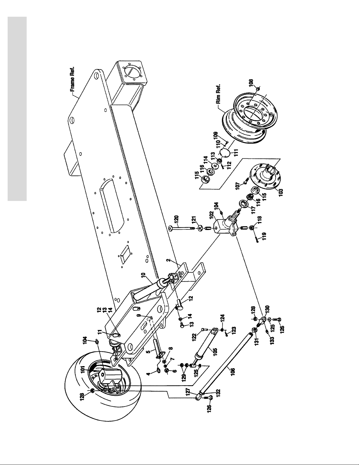
FIGURE 1-1. FRAME AND STEERING INSTALLATION - 5’-9”/1.75M 2WD FRAME (WITH SINGLE
ROD CYLINDER)
FIG & ITEM # PART NUMBER DESCRIPTION QTY. REV.
FRAME OPTIONS Ref.
2360288 Fixed Axle (Standard Stability/Standard Platform) 1
2360283 Oscillating Axle (Standard Stability/Standard Platform 1
2360322 Fixed Axle (2 to 1 Stability/Low Mount Platform) 1
2360321 Oscillating Axle (2 to 1 Stability/Low Mount Platform) 1
S
E
C
T
I
O
N
0239196 OSCILLATING AXLE INSTALLATION (OPTIONAL) Ref. B
1Not Used
2 4843094 Axle Weldment 1
3Not Used
4 2160002 Fitting, Grease 1
5 4842621 Pin, Pivot 1
6 3311601 Nut 3/8”-16NC 1
7 4761600 Lockwasher 3/8” 1
8 4751600 Flatwasher 3/8” 1
9 4300034 Stud (Welded on Part) 1
10 1681785 Lockout Cylinder Assembly (See Section 5 for
Breakdown)
11 4842622 Pin (Top) 2
12 4842794 Pin (Bottom) 2
13 0641406 Bolt 1/4”-20NC x 3/4” 4
14 4761400 Lockwasher 1/4” 4
4751400 Flatwasher 1/4” 4
STEERING INSTALLATION Ref.
0239197 ANSI Spec Ref. E
0252114 CSA Spec Ref. C
1
F
R
A
M
E
2
101 Spindle - Right Side Options: 1
4130207 ANSI Spec
4130264 CSA Spec
0960839 Bushing, Bronze 2
102 Spindle Left Side Options: 1
4130210 ANSI Spec
4130265 CSA Spec
0960839 Bushing, Bronze 2
103 2780153 Hub, Wheel (Includes Item 107) 2
104 2160002 Fitting, Grease 3
105 1682020 Steer Cylinder Assembly (See Section 5 for
Breakdown)
106 3840962 Tie-Rod 1
107 0630137 Stud, Wheel (Part of Item 103) 18
108 3300012 Nut, Wheel 18
109 0721003 Bolt #10-24NC x 3/8” 6
110 4761000 Lockwasher #10 6
111 1120019 Cap, Hub 2
3120626 1-3
1

SECTION 1 FRAME
S
E
C
T
I
O
N
1
F
R
A
M
E
FIGURE 1-1. FRAME AND STEERING INSTALLATION - 5’-9”/1.75M 2WD FRAME (WITH SINGLE
ROD CYLINDER) (CONTINUED)
FIG & ITEM # PART NUMBER DESCRIPTION QTY. REV.
112 3450608 Pin, Cotter 3/16” x 2" 2
113 3322603 Nut, Slotted 1"-12NF 2
114 4740001 Washer, Hardened 2
115 0440112 Cup, Bearing 2
116 0440113 Cone, Bearing 2
117 3960373 Seal, Oil 2
118 3323003 Nut, Slotted 1 1/4”-12NF 2
119 3450609 Pin, Cotter 3/16” x 2 1/4” 2
120 Kingpin Options: 2
3421340 ANSI Spec
3421965 CSA Spec
121 0440162 Washer, Thrust 2
122 3431622 Pin, Clevis 1
123 3450608 Pin, Cotter 3/16” x 2" 1
124 4712600 Flatwasher 1" 1
125 0440091 Washer, Thrust 3
126 0642628 Bolt 1"-8NC x 3 1/2” 2
127 0560805 Block, Tie-Rod (Right Side) 1
128 3312602 Nut, Jam 1"-8NC 2
129 3300175 Locknut 1
130 0560804 Block, Tie-Rod (Left Side) 1
131 3300229 Nut, Jam (Left Hand Thread) 1
132 3323002 Nut, Jam 1 1/4”-12NF 1
133 2160003 Fitting, Grease - 45° 2
1-4 3120626

SECTION 1 FRAME
FIGURE 1-1. FRAME AND STEERING INSTALLATION - 5’-9”/1.75M 2WD FRAME (WITH SINGLE
ROD CYLINDER) (CONTINUED)
FIG & ITEM # PART NUMBER DESCRIPTION QTY. REV.
S
E
C
T
I
O
N
1
F
R
A
M
E
3120626 1-5
SECTION 1 FRAME
S
E
C
T
I
O
N
1
F
R
A
M
E
FIGURE 1-2. FRAME AND STEERING INSTALLATION - 6’-6”/2m 2WD FRAME (WITH DOUBLE ROD CYLINDER)
1-6 3120626

SECTION 1 FRAME
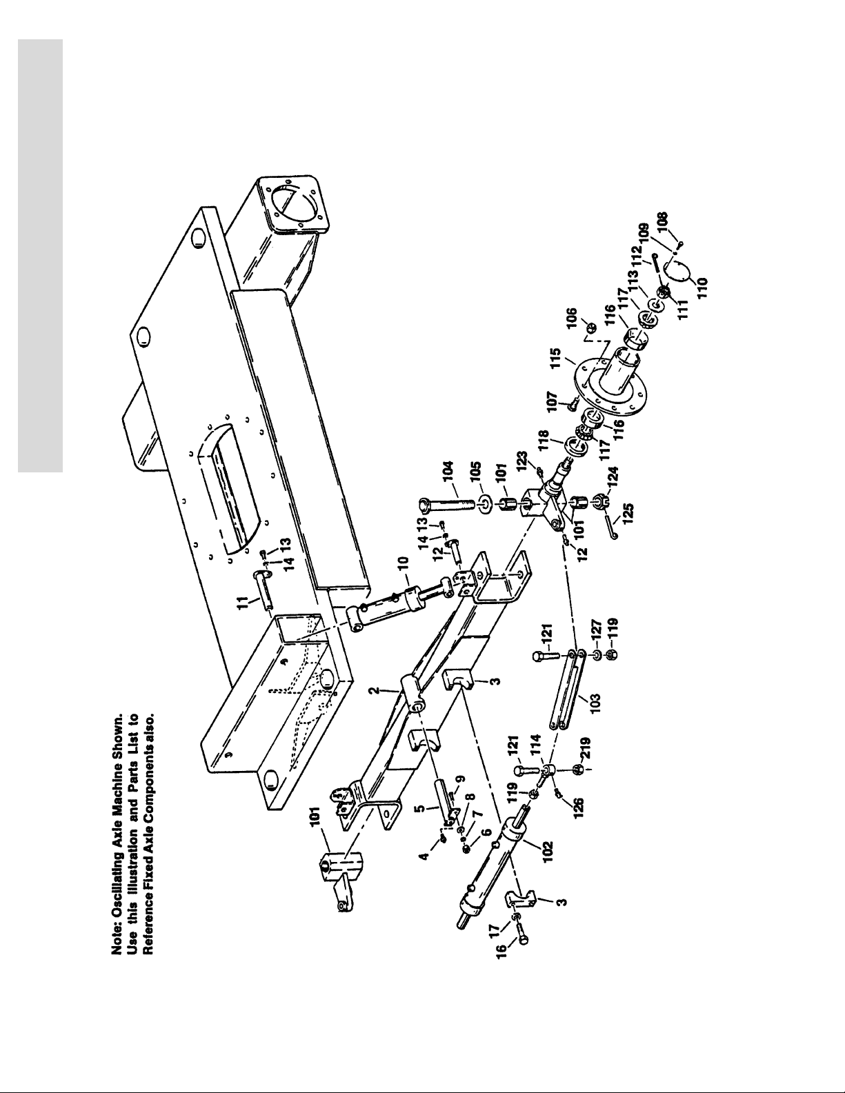
FIGURE 1-2. FRAME AND STEERING INSTALLATION - 6’-6”/2M 2WD FRAME (WITH DOUBLE ROD
CYLINDER)
FIG & ITEM # PART NUMBER DESCRIPTION QTY. REV.
FRAME OPTIONS Ref.
2360262 Fixed Axle
2360274 Oscillating Axle
S
E
C
T
I
O
0238747 OSCILLATING AXLE INSTALLATION (OPTIONAL) Ref. A
1Not Used
2 4842982 Axle Weldment 1
3 0238390 Mounting Block Assembly - Steer Cylinder 2
4 2160002 Fitting, Grease 1
5 4842621 Pin, Pivot (Axle) 1
6 3311601 Nut 3/8”-16NC 1
7 4761600 Lockwasher 3/8” 1
8 4751600 Flatwasher 3/8” 1
9 4300034 Stud (Welded on Part) 1
10 1681785 Lockout Cylinder Assembly (See Section 5 for
Breakdown)
11 4842622 Pin (Top) (Lockout Cylinder) 2
12 4842794 Pin (Bottom) (Lockout Cylinder) 2
13 0641406 Bolt 1/4”-20NC x 3/4” 4
14 4761400 Lockwasher 1/4” 4
STEERING INSTALLATION Ref.
0238395 ANSI Spec Ref. 7
0252113 CSA Spec Ref. 3
101 Spindle Options: 2
4130197 ANSI Spec
4130263 CSA Spec
0960839 Bushing, Bronze 2
102 Steer Cylinder Assembly Options (See Section 5 for
Breakdown)
1681814 Prior to S/N 31941
1683511 S/N 31941 to Present
103 4842860 Tie-Rod 2
104 Kingpin Options: 2
3421340 ANSI Spec
3421965 CSA Spec
105 0440162 Washer, Thrust 2
106 3300012 Nut, Wheel 1/2”-20NF 18
107 0630137 Bolt, Wheel (Part of Item 115) 18
108 0721004 Bolt #10-24 x 1/2” 6
109 4761000 Lockwasher #10 6
110 1120019 Cap, Hub 2
111 3322603 Nut, Slotted 1"-12NF 2
112 3450608 Pin, Cotter 3/16” x 2" 2
113 4740001 Washer, Hardened 2
114 4842624 Block, Tie-Rod 2
N
1
F
R
A
M
2
1
E
3120626 1-7

SECTION 1 FRAME
S
E
C
T
I
O
N
1
F
R
A
M
E
FIGURE 1-2. FRAME AND STEERING INSTALLATION - 6’-6”/2M 2WD FRAME (WITH DOUBLE ROD
CYLINDER) (CONTINUED)
FIG & ITEM # PART NUMBER DESCRIPTION QTY. REV.
115 2780153 Hub, Wheel
116 0440112 Cup, Bearing 4
117 0440113 Cone, Bearing 4
118 3960373 Seal, Oil 2
119 3312205 Locknut 3/4”-10NC 6
120 Not Used
121 0642224 Bolt 3/4”-10NC x 3" 4
122 Not Used
123 2160002 Fitting, Grease - Straight 2
124 3323003 Nut, Slotted 1 1/4”-12NF 2
125 3450609 Pin, Cotter 3/16” x 2 1/4” 2
126 2160001 Fitting, Grease - 90° 4
127 4740156 Washer, Thrust 2
1-8 3120626

SECTION 1 FRAME
FIGURE 1-2. FRAME AND STEERING INSTALLATION - 6’-6”/2M 2WD FRAME (WITH DOUBLE ROD
CYLINDER) (CONTINUED)
FIG & ITEM # PART NUMBER DESCRIPTION QTY. REV.
S
E
C
T
I
O
N
1
F
R
A
M
E
3120626 1-9
SECTION 1 FRAME
S
E
C
T
I
O
N
1
F
R
A
M
E
FIGURE 1-3. FRAME AND STEERING INSTALLATION 6’-6”/2m 4WD FRAME
1-10 3120626

SECTION 1 FRAME
S
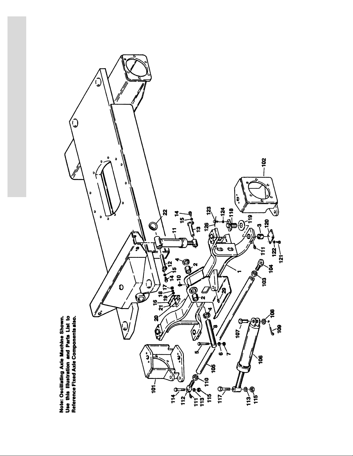
FIGURE 1-3. FRAME AND STEERING INSTALLATION 6’-6”/2M 4WD FRAME
FIG & ITEM # PART NUMBER DESCRIPTION QTY. REV.
FRAME OPTIONS Ref.
2360277 Fixed Axle (Machines with 8.75" and 9.5" Tires) 1
2360392 Fixed Axle (Machines with 12" Tires) 1
2360272 Oscillating Axle (Machines with 8.75" and 9.5" Tires) 1
2360393 Oscillating Axle (Machines with 12" Tires) 1
0238631 OSCILLATING AXLE INSTALLATION (OPTIONAL) Ref. D
1 4842930 Axle Weldment 1
2 0961003 Bushing, Bronze (Axle Pivot) 2
3 0961029 Bushing, Bronze (Steer Pivot) 4
4 4740158 Washer, Thrust 2
5 0641630 Bolt 3/8”-16NC x 3 3/4” 1
6 4751600 Flatwasher 3/8” 1
7 3311605 Locknut 3/8”-16NC 1
8 3421500 Pin, Pivot (Axle) 1
9Not Used
10 2160002 Fitting, Grease - Straight 1
11 1681785 Lockout Cylinder Assembly (See Section 5 for
Breakdown)
12 4842622 Pin, Attach (Top) (Lockout Cylinder) 2
13 4842794 Pin, Attach (Bottom) (Lockout Cylinder) 2
14 0641406 Bolt 1/4”-20NC x 3/4” 4
15 4761400 Lockwasher 1/4” 4
4751400 Flatwasher 1/4” 4
16 4220115 Stop, Axle 2
17 3311801 Nut 1/2”-13NC 4
18 4761800 Lockwasher 1/2” 4
19 4751800 Flatwasher 1/2” 4
20 4300045 Stud (Welded on Part) 4
21 4070690 Shim A/R
22 0961127 Bushing, Snap 2
2
E
C
T
I
O
N
1
F
R
A
M
E
STEERING INSTALLATION Ref.
0238637 ANSI Spec Ref. E
0252271 CSA Spec Ref. C
101 4130192 Spindle (Right Side) 1
102 4130190 Spindle (Left Side) 1
103 3300229 Nut, Jam (Left Hand Thread) 1
104 0560714 Block, Tie-Rod (Left Side) 1
105 3840861 Tie-Rod 1
106 1681892 Steer Cylinder Assy (See Section 5 for Breakdown) 1
107 3431622 Pin, Clevis 1
108 4712600 Flatwasher 1" Narrow 1
109 3450606 Pin, Cotter 3/16” x 1 1/2” 1
110 3323002 Nut, Jam 1 1/4”-12NF 1
111 2160002 Fitting, Grease 6
3120626 1-11

SECTION 1 FRAME
S
E
C
T
I
O
N
1
F
R
A
M
E
FIGURE 1-3. FRAME AND STEERING INSTALLATION 6’-6”/2M 4WD FRAME (CONTINUED)
FIG & ITEM # PART NUMBER DESCRIPTION QTY. REV.
112 0560605 Block, Tie-Rod (Right Side) 1
113 0440091 Washer, Thrust 3
114 0642628 Bolt 1"-8NC x 3 1/2” 2
115 3312602 Nut, Jam 1"-8NC 3
116 Not Used
117 0630369 Bolt, Special 1
118 Kingpin Options: 4
3421190 ANSI Spec
3421887 CSA Spec Prior to S/N 26766
3421190 CSA Spec S/N 26766 to Present
119 0440161 Bearing, Thrust 2
120 Plate, Cover Options: 4
3530244 Prior to August 1992
3536410 August 1992 to Present
121 0641404 Bolt 1/4”-20NC x 1/2” (Prior to August 1992) 8
4300106 Drivescrew (August 1992 to Present) 8
122 4761400 Lockwasher 1/4” (Prior to August 1992 Only) 8
123 0630083 Bolt, Special 8
124 4761600 Lockwasher 3/8” 8
125 Not Used
126 4920096 Wire, Safety 4 ft./20cm
— — — — — — — — — —
0100011 Loctite #242 A/R
1-12 3120626

SECTION 1 FRAME
FIGURE 1-3. FRAME AND STEERING INSTALLATION 6’-6”/2M 4WD FRAME (CONTINUED)
FIG & ITEM # PART NUMBER DESCRIPTION QTY. REV.
S
E
C
T
I
O
N
1
F
R
A
M
E
3120626 1-13
SECTION 1 FRAME
S
E
C
T
I
O
N
1
F
R
A
M
E
FIGURE 1-4. TIRE AND WHEEL DRIVE INSTALLATIONS
1-14 3120626

SECTION 1 FRAME
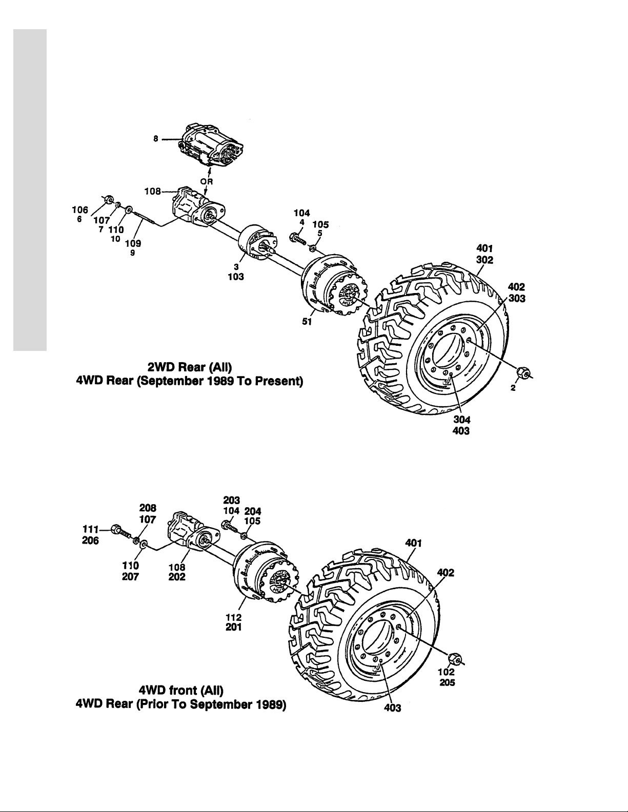
FIGURE 1-4. TIRE AND WHEEL DRIVE INSTALLATIONS
FIG & ITEM # PART NUMBER DESCRIPTION QTY. REV.
WHEEL DRIVE INSTALLATIONS (2WD) Ref.
0238521 Gas/Diesel Machines Built Prior to October 1992 &
All Electric Machines Built to Present
0253630 Gas/Diesel Machines Built October 1992 to Present
(Standard)
0270217 Gas/Diesel Machines (Post Production Alternative)
(Standard)
0256126 Gas/Diesel Machines Built October 1992 to Present
(15% Maximum Gradability)
0250218 Gas/Diesel Machines (Post Production Alternative)
(15% Maximum Gradability)
1 Drive Hub Assembly Options (See Figure 1-5 for
Breakdown):
Electric Machines:
2780134
See Note
2780168 March 1989 to Present (W1BF Stamped on ID
2780134
See Note
2780168 March 1989 to October 1992 (W1BF Stamped
2780169 October 1992 to Present (Standard)
2780167 October 1992 to Present (15% Max Gradability)
2 3300012 Nut, Wheel 18
3 Drive Brake Assembly Options: 2
0920072 Prior to January 1992 (Ausco) (See Figure 1-7 for
0920084 January 1992 to S/N 33476 (Mico) (See Figure 1-8
0920110 S/N 33476 to Present (Mico) (See Figure 1-8 for
0920119 Optional Brake (Mico) (May be used as alternative)
7018612 Repair Kit - 0920117/0920119 Brake (Includes
7000731 Gasket, Mounting Face 2
4 0642016 Bolt 5/8”-11NC x 2" 12
5 4762000 Lockwasher 5/8” 12
6 3311801 Nut 1/2”-13NC 4
7 4761800 Lockwasher 1/2” 4
Prior to March 1989 (W1B1 Stamped on ID
Plate)
Note: When replacing complete hub recommend
using 2780168 Hub Assembly.
Plate)
Gas/Diesel Machines:
Prior to March 1989 (W1B1 Stamped on ID
Plate)
Note: When replacing complete hub recommend
using 2780168 Hub Assembly.
on ID Plate)
Breakdown)
for Breakdown)
Breakdown)
(was p/n 0920117)
Case Seal, Piston Inner & Outer O-Rings &
Back-up Rings, Stator Disc, Rotor Disc, Return
Plate, Springs, Oil Seal, Bearing, 2 Retaining
Rings & 2 Mounting Face Gaskets) (1 Per
Assembly)
Ref. C
Ref. —
Ref. 1
Ref. —
Ref. 1
2
1
S
E
C
T
I
O
N
1
F
R
A
M
E
3120626 1-15

SECTION 1 FRAME
S
E
C
T
I
O
N
1
F
R
A
M
E
FIGURE 1-4. TIRE AND WHEEL DRIVE INSTALLATIONS (CONTINUED)
FIG & ITEM # PART NUMBER DESCRIPTION QTY. REV.
8 Use 1001096405 Drive Motor Assembly (See Figure 1-9 for
Breakdown) (was p/n 3160132)
9 4300092 Stud 1/2” x 5 1/2” 4
10 4751800 Flatwasher 1/2” 4
0250432 WHEEL DRIVE INSTALLATION (4WD BUILT
SEPTEMBER 1989 TO PRESENT) (REAR DRIVE HAS
SEPARATE HUB AND BRAKE)
0270158 WHEEL DRIVE INSTALLATION (4WD) (POST
PRODUCTION ALTERNATIVE)
101 Drive Hub Assembly - Rear Options (See Figure 1-5 for
Breakdown):
2780175 September 1989 to November 1992
2780167 November 1992 to Present
102 3300012 Nut, Wheel 36
103 Drive Brake Assembly Options: 2
0920072 September 1989 to January 1992 (Ausco) (See
Figure 1-7 for Breakdown)
0920084 January 1992 to S/N 33476 (Mico) (See Figure 1-8
for Breakdown)
0920110 S/N 33476 to Present (Mico) (See Figure 1-8 for
Breakdown)
0920119 Optional Brake (Mico) (May be used as alternative)
(was p/n 0920117)
7018612 Repair Kit - 0920117/0920119 Brake (Includes
Case Seal, Piston Inner & Outer O-Rings & Backup Rings, Stator Disc, Rotor Disc, Return Plate,
Springs, Oil Seal, Bearing, 2 Retaining Rings & 2
Mounting Face Gaskets) (1 Per Assembly)
7000731 Gasket, Mounting Face 2
104 0642014 Bolt 5/8”-11NC x 2" 24
105 4762000 Lockwasher 5/8” 24
106 3311801 Nut 1/2”-13NC 4
107 4761800 Lockwasher 1/2” 8
108 3160130 Drive Motor Assembly (See Figure 1-10 for Breakdown) 4
109 4300092 Stud 1/2”-13NC x 5 1/2” 4
110 4751800 Flatwasher 1/2” 8
111 0641810 Bolt 1/2”-13NC x 1 1/4” 4
112 Drive Hub/Brake Assembly - Front Options (See Figure
1-6 for Breakdown)
2780150 September 1989 to August 1992
2780193 August 1992 to November 1992
2780191 November 1992 to Present
2
Ref. C
Ref. 1
2
1
2
0238859 WHEEL DRIVE INSTALLATION (4WD BUILT PRIOR TO
SEPTEMBER 1989) (REAR DRIVE HAS COMBINED
HUB & BRAKE)
201 2780150 Drive Hub/Brake Assembly - Front & Rear (See Figure
1-6 for Breakdown)
202 3160130 Drive Motor Assembly (See Figure 1-10 for Breakdown) 4
1-16 3120626
2
4

SECTION 1 FRAME
FIGURE 1-4. TIRE AND WHEEL DRIVE INSTALLATIONS (CONTINUED)
FIG & ITEM # PART NUMBER DESCRIPTION QTY. REV.
203 0642014 Bolt 5/8”-11NC x 1 3/4” 24
204 4762000 Lockwasher 5/8” 24
205 3300012 Nut, Wheel 36
206 0641810 Bolt 1/2”-13NC 8
207 4751800 Flatwasher 1/2” 8
208 4761800 Lockwasher 1/2” 8
TIRE AND WHEEL OPTIONS (2WD) Ref.
301 Tire and Wheel Options (2WD Front) (Not Shown) A/R
0237850 Tire and Wheel Assembly - Pneumatic - 8.75" x 16.5" 2
Use 4520143 Tire - 8.75" x 16.5" (Firestone Transport I) 2
0238769 Tire and Wheel Assembly - Pneumatic - 8.75" x 16.5" 2
Use 4520143 Tire - 8.75" x 16.5" (Goodyear Tracker LT11) 2
0239396 Tire and Wheel Assembly - Pneumatic - 9.50" x 16.5" 2
4520110 Tire - 9.50" x 16.5" (General Jumbo GLT) 2
0238135 Tire and Wheel Assembly - Foam-Filled 8.75" x 16.5"
(Firestone)
0238773 Tire and Wheel Assembly - Foam-Filled 8.75" x 16.5"
(Goodyear)
Use 0253131 Tire and Wheel Assembly - Foam Filled 8.75" x
16.5"LT (Goodyear Unisteel) (Prior to S/N 31086)
0253131 Tire and Wheel Assembly - Foam-Filled 8.75" x 16.5"
LT (Galaxy) (S/N 31086 to Present)
0239806 Tire and Wheel Assembly - Foam-Filled 9.5" x 16.5"
(General)
Note: Assemblies may require ballast/foam filling to
manufacture’s specifications prior to installing on a
machine. Refer to Operation & Safety or Service &
Maintenance Manuals. Purchase individual tire and
/or rim only if able to foam fill tire & wheel assembly, otherwise, purchase complete assembly.
302 Tire and Wheel Options (2WD Rear) A/R
0237851 Tire and Wheel Assembly - Pneumatic 8.75" x 16.5" 2
Use 4520143 Tire - 8.75" x 16.5" (Firestone Town and Country)
(Prior to S/N 31086)
Use 4520199 Tire - 8.75" x 16.5" (Galaxy) (S/N 31086 to
Present)
0238770 Tire and Wheel Assembly - Pneumatic 8.75" x 16.5" 2
Use 4520143 Tire - 8.75" x 16.5" (Goodyear Custom X-Tra Grip
Hi-Miller) (Prior to S/N 31086)
Use 4520199 Tire - 8.75" x 16.5" (Galaxy) (S/N 31086 to
Present)
0239397 Tire and Wheel Assembly - Pneumatic 9.5" x 16.5"
Rear (Optional)
4520111 Tire - 9.5" x 16.5" (General Jumbo GLT) 2
0238136 Tire and Wheel Assembly - Foam-Filled 8.75" x 16.5"
Rear (Firestone)
0238774 Tire and Wheel Assembly - Foam-Filled 8.75" x 16.5"
(Goodyear)
Use 0253131 Tire and Wheel Assembly - Foam-Filled 8.75" x 16.5"
LT (Goodyear Unisteel) (Prior to S/N 31086)
2
2
2
2
2
Ref.
2
2
2
2
2
2
2
2
S
E
C
T
I
O
N
1
F
R
A
M
E
3120626 1-17

SECTION 1 FRAME
S
E
C
T
I
O
N
1
F
R
A
M
E
FIGURE 1-4. TIRE AND WHEEL DRIVE INSTALLATIONS (CONTINUED)
FIG & ITEM # PART NUMBER DESCRIPTION QTY. REV.
302 (cont’d) 0253131 Tire and Wheel Assembly - Foam-Filled 8.75" x 16.5"
LT (Galaxy) (S/N 31086 to Present)
0239805 Tire and Wheel Assembly - Foam-Filled 9.5" x 16.5"
(General)
Note: Assemblies may require ballast/foam filling
to manufacture’s specifications prior to installing
on a machine. Refer to Operation & Safety or Service & Maintenance Manuals. Purchase individual
tire and /or rim only if able to foam fill tire & wheel
assembly, otherwise, purchase complete assembly.
303 Rim Options: 4
4842561 Rim (8.75" Tires)
4842994 Rim (9.5" Tires)
304 4640392 Valve, Air 4
TIRE AND WHEEL OPTIONS (4WD) Ref.
401 Tire and Wheel Options (4WD Front and Rear) A/R
0237851 Tire and Wheel Assembly - Pneumatic 8.75" x 16.5" 4
Use 4520143 Tire - 8.75" x 16.5" (Firestone) (Prior to S/N 31086) 4
Use 4520199 Tire - 8.75" x 16.5" (Galaxy) (S/N 31086 to
Present)
0238770 Tire and Wheel Assembly - Pneumatic 8.75" x 16.5" 4
Use 4520143 Tire - 8.75" x 16.50" (Goodyear) (Prior to S/N 4
31086)
Use 4520199 Tire - 8.75" x 16.5" (Galaxy) (S/N 31086 to
Present)
0239397 Tire and Wheel Assembly - Pneumatic 9.5" x 16.5" 4
4520106 Tire - 9.5" x 16.50" (General GLT Traction II) 4
0251260 Tire and Wheel Assembly - LH Side Pneumatic 12" x
16.5" (NHS)
0251259 Tire and Wheel Assembly - RH Side Pneumatic 12" x
16.5" (NHS)
4520129 Tire - 12" x 16.5" (NHS) 4
0238136 Tire and Wheel Assembly - Foam-Filled 8.75" x 16.5"
(Firestone)
0238774 Tire and Wheel Assembly - Foam-Filled 8.75" x 16.5"
(Goodyear)
Use 0253131 Tire and Wheel Assembly - Foam-Filled 8.75" x 16.50
LT (Goodyear Unisteel) (Prior to S/N 31086)
0253131 Tire and Wheel Assembly - Foam-Filled 8.75" x 16.5"
LT (Galaxy) (S/N 31086 to Present)
0239806 Tire and Wheel Assembly - Foam-Filled 9.5" x 16.5"
(General)
Note: Assemblies may require ballast/foam filling
to manufacture’s specifications prior to installing
on a machine. Refer to Operation & Safety or Service & Maintenance Manuals. Purchase individual
tire and /or rim only if able to foam fill tire & wheel
assembly, otherwise, purchase complete assembly.
2
2
Ref.
4
4
2
2
4
4
4
4
4
Ref.
1-18 3120626

SECTION 1 FRAME
FIGURE 1-4. TIRE AND WHEEL DRIVE INSTALLATIONS (CONTINUED)
FIG & ITEM # PART NUMBER DESCRIPTION QTY. REV.
402 Rim Options: 4
4842561 Rim (8.75" Tires)
4842994 Rim (9.5" Tires)
4860126 Rim (12" Tires) 4
403 4640392 Valve, Air 4
S
E
C
T
I
O
N
1
F
R
A
M
E
3120626 1-19
SECTION 1 FRAME
S
E
C
T
I
O
N
1
F
R
A
M
E
FIGURE 1-5. DRIVE HUB ASSEMBLIES
1-20 3120626

SECTION 1 FRAME
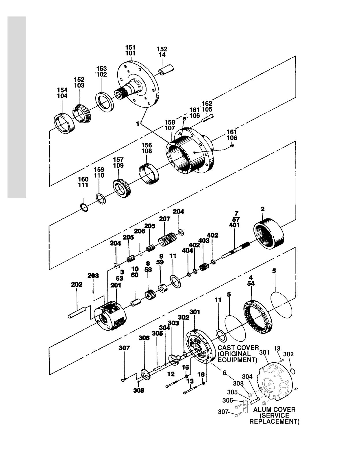
FIGURE 1-5. DRIVE HUB ASSEMBLIES
FIG & ITEM # PART NUMBER DESCRIPTION QTY. REV.
DRIVE HUB ASSEMBLIES Ref.
1 Hub-Spindle Sub-Assembly Options: 1
7010428 All except 2780134 Hub
(See Items 101-111 for Breakdown)
7000245 2780134 Hub (See Items 151-162 for Breakdown)
2 7000246 Gear, Internal 1
3 Carrier Assembly (See Items 201-207) 1
4 Gear, Ring (See Item 54 for Options) 1
5 7000230 O-Ring 2
6 Cover Assembly (Includes Items 301-308) 1
7 Input Shaft Assembly (See Item 57 for Options) 1
8 Gear, Input (See Item 58 for Options) 1
9 Spacer, Thrust (See Items 59 for Options) 1
10 Spacer, Thrust (See Item 60 for Options) 1
11 7000253 Washer, Thrust 2
7017096 Spacer (Aluminum Cover (Service Replacement)) 1
12 Bolt Options: 12
7000217 Cast Cover (Original Equipment)
7017067 Aluminum Cover (Service Replacement)
13 Hardware Options: 4
7000214 Bolt Used on Cast Cover (Original Equipment)
7017080 Dowel Pin Used Aluminum Cover (Service Replace-
ment)
14 7000206 Coupling 1
15 Not Used
16 7007603 Flatwasher 16
S
E
C
T
I
O
N
1
F
R
A
M
E
DRIVE HUB ASSEMBLIES Ref.
Electric Machines: Ref.
2780134 Prior To March 1989 Ref. —
2780168 March 1989 To Present Ref. —
Gas/Diesel Machines Ref.
2780134 2WD Prior To March 1989 Ref. —
2780168 2WD March 1989 To October 1992 Ref. —
2780169 2WD October 1992 to September 1995 Ref. —
2780167 2WD September 1995 to Present Ref. —
2780175 4WD Rear Drive Only September 1989 To
November 1992
2780167 4WD Rear Drive Only November 1992 To Present Ref. —
51 to 52 Not Used
53 Carrier Assembly Options (See items 201-207 for
Breakdown):
7000202 2780134/2780168/2780175 Hubs
7000247 2780167/2780169 Hubs
54 Gear, Ring Options: 1
7007634 2780134/2780175 Hubs
7000203 2780168 Hub
7000248 2780167/2780167 Hubs
Ref. —
1
3120626 1-21

SECTION 1 FRAME
S
E
C
T
I
O
N
1
F
R
A
M
E
FIGURE 1-5. DRIVE HUB ASSEMBLIES (CONTINUED)
FIG & ITEM # PART NUMBER DESCRIPTION QTY. REV.
55 to 56 Not Used
57 Input Shaft Assembly Options (See items 401-404
for Breakdown):
7000250 2WD Machines
7007650 4WD Machines
58 Gear, Input Options: 1
7000201 Electric Machines
7000201 2WD Gas/Diesel Machines (Prior to October
1992)
7000251 2WD Gas/Diesel Machines (October 1992 to
Present)
7007652 4WD Machines
59 Spacer, Thrust Options: 1
7000252 2WD Machines
7007653 4WD Machines
60 Spacer, Thrust Options: A/R
Not Required 2WD Machines 0
7007654 4WD Machines 1
7010428 HUB - SPINDLE SUB-ASSEMBLY (2780167/2780168/
2780169/2780175 HUBS)
1
Ref.
101 7001997 Spindle 1
102 Use 2900034 Seal 1
103 Use 7010429 Cone, Bearing 1
104 Use 7010429 Cup, Bearing 1
105 7007697 Bolt, Wheel 9
106 7000242 Plug, Pipe 2
107 7007601 Hub 1
108 7000257 Cup, Bearing 1
109 7000258 Cone, Bearing 1
110 Use 2900034 Spacer 1
111 Use 2900034 Ring, Retaining 1
7000245 HUB - SPINDLE SUB-ASSEMBLY (2780134 HUBS) Ref.
151 7000254 Spindle 1
152 7000206 Coupling 1
153 Use 2900661 Seal 1
154 7000255 Cup, Bearing 1
155 7000256 Cone, Bearing 1
156 7000257 Cup, Bearing 1
157 7000258 Cone, Bearing 1
158 7000259 Hub 1
159 Use 2900661 Spacer 1
160 Use 2900661 Ring, Retaining 1
161 7000242 Pipe Plug 2
162 7000241 Stud 9
1-22 3120626
 Loading...