

Operation & Safety Manual
Model
25RTS
33RTS
40RTS
3120690
May 15, 2003

– JLG Sizzor –

This page left blank intentionally.
– JLG Sizzor –

FOREWORD
FOREWORD
This manual is a very important tool! Keep it with the machine at all times.
The purpose of this manual is to provide owners, users, operators, lessors, and lessees with the precautions
and operating procedures essential for the safe and proper machine operation for its intended purpose.
Due to continuous product improvements, JLG Industries, Inc. reserves the right to make specification changes
without prior notification. Contact JLG Industries, Inc. for updated information.
3120690 – JLG Lift – 5
FOREWORD
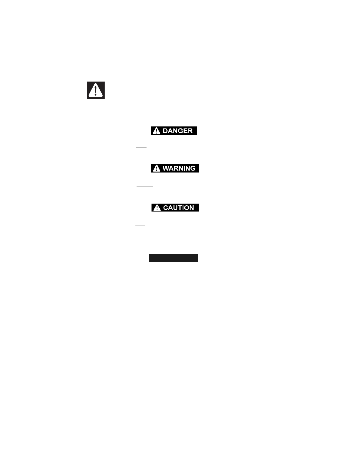
SAFETY ALERT SYMBOLS AND SAFETY SIGNAL WORDS
This is the Safety Alert Symbol. It is used to alert you to the
potential personal injury hazards. Obey all safety messages
that follow this symbol to avoid possible injury or death
INDICATES AN IMMINENTLY HAZARDOUS SITUATION WHICH, IF
NOT AVOIDED, WILL
THE MACHINE THIS WILL HAVE A RED BACKGROUND.
INDICATES A POTENTIALITY HAZARDOUS SITUATION WHICH, IF
NOT AVOIDED, COULD
ON THE MACHINE THIS WILL HAVE AN ORANGE BACKGROUND.
RESULT IN SERIOUS INJURY OR DEATH. ON
RESULT IN SERIOUS INJURY OR DEATH.
INDICATES A POTENTIALITY HAZARDOUS SITUATION WHICH IF
NOT AVOIDED, MAY
MAY ALSO BE USED TO ALERT AGAINST UNSAFE PRACTICES. ON
THE MACHINE THIS WILL HAVE A YELLOW BACKGROUND.
RESULT IN MINOR OR MODERATE INJURY. IT
IMPORTANT
INDICATES PROCEDURES ESSENTIAL FOR SAFE OPERATION AND
WHICH, IF NOT FOLLOWED, MAY RESULT IN A MACHINE MALFUNCTIONED DAMAGE. ON THE MACHINE THIS WILL HAVE A
GREEN BACKGROUND.
6 – JLG Lift – 3120690

FOREWORD
THIS PRODUCT MUST COMPLY WITH ALL SAFETY RELATED BULLETINS. CONTACT JLG INDUSTRIES, INC. OR THE LOCAL AUTHORIZED JLG REPRESENTATIVE FOR INFORMATION REGARDING SAFETY-RELATED BULLETINS WHICH MAY HAVE BEEN ISSUED FOR
THIS PRODUCT.
MODIFICATION OR ALTERATION OF AN AERIAL WORK PLATFORM SHALL BE MADE ONLY WITH WRITTEN PERMISSION FROM THE
MANUFACTURER
IMPORTANT
JLG INDUSTRIES, INC. SENDS SAFETY RELATED BULLETINS TO THE OWNER OF RECORD OF THIS MACHINE. CONTACT JLG INDUSTRIES, INC. TO ENSURE THAT THE CURRENT OWNER RECORDS ARE UPDATED AND ACCURATE.
IMPORTANT
JLG INDUSTRIES, INC. MUST BE NOTIFIED IMMEDIATELY IN ALL INSTANCES WHERE JLG PRODUCTS HAVE BEEN INVOLVED IN AN
ACCIDENT INVOLVING BODILY INJURY OR DEATH OF PERSONNEL OR WHEN SUBSTANTIAL DAMAGE HAS OCCURRED TO PERSONAL
FOR :
•Accident Reporting
•Product Safety Publications
•Current Owner Updates
•Questions Regarding Product Safety
•Standards and Regulations Compliance Information
•Questions Regarding Special Product Applications
•Questions Regarding Product Modifications
CONTACT :
Product Safety and Reliability Department
JLG Industries, Inc.
1 JLG Drive
McConnellsburg, PA 17233
In USA:
Toll Free: 877-JLG-SAFE
877-554-7233
Outside USA:
717-485-5161
E-mail: ProductSafety@JLG.com
3120690 – JLG Lift – 7

FOREWORD
REVISION LOG
Original Issue - March 1, 1993
Revised - May 23, 1999
Revised - July 22, 1999
Revised - September 2, 1999
Revised - October 29, 1999
Revised - May 5, 2000
Revised - October 15, 2001
Revised - May 15, 2003
8 – JLG Lift – 3120690

TABLE OF CONTENTS
TABLE OF CONTENTS
SUBJECT - SECTION, PARAGRAPH PAGE NO.
SECTION -
SECTION - FOREWORD
SECTION 1 - SAFETY PRECAUTIONS
1.1 General . . . . . . . . . . . . . . . . . . . . . . . . . . . . . . . . . . . . . . . . . . . . . . . . . . . . . . . . . . . . . . . . . . . . . .1-1
1.2 Pre-operation. . . . . . . . . . . . . . . . . . . . . . . . . . . . . . . . . . . . . . . . . . . . . . . . . . . . . . . . . . . . . . . . . .1-1
1.3 Operation . . . . . . . . . . . . . . . . . . . . . . . . . . . . . . . . . . . . . . . . . . . . . . . . . . . . . . . . . . . . . . . . . . . . . 1-2
1.4 Towing, Lifting, and Hauling . . . . . . . . . . . . . . . . . . . . . . . . . . . . . . . . . . . . . . . . . . . . . . . . . . . . . .1-4
1.5 Additional Hazards / Safety. . . . . . . . . . . . . . . . . . . . . . . . . . . . . . . . . . . . . . . . . . . . . . . . . . . . . . .1-4
SECTION 2 - PREPARATION AND INSPECTION
2.1 General . . . . . . . . . . . . . . . . . . . . . . . . . . . . . . . . . . . . . . . . . . . . . . . . . . . . . . . . . . . . . . . . . . . . . .2-1
2.2 Preparation For Use . . . . . . . . . . . . . . . . . . . . . . . . . . . . . . . . . . . . . . . . . . . . . . . . . . . . . . . . . . . .2-1
2.3 Delivery And Periodic Inspection . . . . . . . . . . . . . . . . . . . . . . . . . . . . . . . . . . . . . . . . . . . . . . . . . .2-1
2.4 Daily Walk-around Inspection . . . . . . . . . . . . . . . . . . . . . . . . . . . . . . . . . . . . . . . . . . . . . . . . . . . . .2-3
2.5 Daily Functional Check . . . . . . . . . . . . . . . . . . . . . . . . . . . . . . . . . . . . . . . . . . . . . . . . . . . . . . . . . .2-7
2.6 Lock-out Cylinder Check - (If Equipped) . . . . . . . . . . . . . . . . . . . . . . . . . . . . . . . . . . . . . . . . . . . .2-7
2.7 Dual Fuel System . . . . . . . . . . . . . . . . . . . . . . . . . . . . . . . . . . . . . . . . . . . . . . . . . . . . . . . . . . . . . .2-10
2.8 Torque Requirements . . . . . . . . . . . . . . . . . . . . . . . . . . . . . . . . . . . . . . . . . . . . . . . . . . . . . . . . . . .2-10
SECTION 3 - USER RESPONSIBILITIES AND MACHINE CONTROL
3.1 General . . . . . . . . . . . . . . . . . . . . . . . . . . . . . . . . . . . . . . . . . . . . . . . . . . . . . . . . . . . . . . . . . . . . . .3-1
3.2 Personnel Training . . . . . . . . . . . . . . . . . . . . . . . . . . . . . . . . . . . . . . . . . . . . . . . . . . . . . . . . . . . . .3-1
3.3 Operating Characteristics and Limitations . . . . . . . . . . . . . . . . . . . . . . . . . . . . . . . . . . . . . . . . . . .3-1
3.4 Controls and Indicators. . . . . . . . . . . . . . . . . . . . . . . . . . . . . . . . . . . . . . . . . . . . . . . . . . . . . . . . . .3-2
SECTION 4 - MACHINE OPERATION
4.1 Description . . . . . . . . . . . . . . . . . . . . . . . . . . . . . . . . . . . . . . . . . . . . . . . . . . . . . . . . . . . . . . . . . . .4-1
4.2 General . . . . . . . . . . . . . . . . . . . . . . . . . . . . . . . . . . . . . . . . . . . . . . . . . . . . . . . . . . . . . . . . . . . . . .4-2
4.3 Engine Operation . . . . . . . . . . . . . . . . . . . . . . . . . . . . . . . . . . . . . . . . . . . . . . . . . . . . . . . . . . . . . .4-2
4.4 Raising and Lowering - (Lifting) . . . . . . . . . . . . . . . . . . . . . . . . . . . . . . . . . . . . . . . . . . . . . . . . . . .4-3
4.5 Leveling Jacks (Optional) . . . . . . . . . . . . . . . . . . . . . . . . . . . . . . . . . . . . . . . . . . . . . . . . . . . . . . . .4-3
4.6 Mechanical Platform Extension (Optional) . . . . . . . . . . . . . . . . . . . . . . . . . . . . . . . . . . . . . . . . . . .4-4
4.7 Steering . . . . . . . . . . . . . . . . . . . . . . . . . . . . . . . . . . . . . . . . . . . . . . . . . . . . . . . . . . . . . . . . . . . . . .4-4
4.8 Traveling - (Driving). . . . . . . . . . . . . . . . . . . . . . . . . . . . . . . . . . . . . . . . . . . . . . . . . . . . . . . . . . . . .4-4
4.9 Parking and Stowing . . . . . . . . . . . . . . . . . . . . . . . . . . . . . . . . . . . . . . . . . . . . . . . . . . . . . . . . . . . .4-5
4.10 Platform Loading . . . . . . . . . . . . . . . . . . . . . . . . . . . . . . . . . . . . . . . . . . . . . . . . . . . . . . . . . . . . . . .4-5
4.11 Safety Props . . . . . . . . . . . . . . . . . . . . . . . . . . . . . . . . . . . . . . . . . . . . . . . . . . . . . . . . . . . . . . . . . .4-5
4.12 Machine Tie Down. . . . . . . . . . . . . . . . . . . . . . . . . . . . . . . . . . . . . . . . . . . . . . . . . . . . . . . . . . . . . .4-5
4.13 Towing . . . . . . . . . . . . . . . . . . . . . . . . . . . . . . . . . . . . . . . . . . . . . . . . . . . . . . . . . . . . . . . . . . . . . . . 4-5
SECTION 5 - EMERGENCY PROCEDURES
5.1 General . . . . . . . . . . . . . . . . . . . . . . . . . . . . . . . . . . . . . . . . . . . . . . . . . . . . . . . . . . . . . . . . . . . . . .5-1
5.2 Emergency Towing Procedures . . . . . . . . . . . . . . . . . . . . . . . . . . . . . . . . . . . . . . . . . . . . . . . . . . .5-1
5.3 Emergency Controls and Their Locations . . . . . . . . . . . . . . . . . . . . . . . . . . . . . . . . . . . . . . . . . . .5-1
5.4 Emergency Operation. . . . . . . . . . . . . . . . . . . . . . . . . . . . . . . . . . . . . . . . . . . . . . . . . . . . . . . . . . . 5-2
5.5 Incident Notification. . . . . . . . . . . . . . . . . . . . . . . . . . . . . . . . . . . . . . . . . . . . . . . . . . . . . . . . . . . . .5-2
SECTION 6 - INSPECTION AND REPAIR LOG
3120690 – JLG Sizzor – i

TABLE OF CONTENTS (Continued)
LIST OF FIGURES
FIGURE NO. TITLE PAGE NO.
2-1. Walk-Around Inspection Diagram. . . . . . . . . . . . . . . . . . . . . . . . . . . . . . . . . . . . . . . . . . . . . . . . . .2-4
2-2. Walk-Around Inspection Points (Sheet 1 of 2) . . . . . . . . . . . . . . . . . . . . . . . . . . . . . . . . . . . . . . . .2-5
2-3. Walk-Around Inspection Points (Sheet 2 of 2) . . . . . . . . . . . . . . . . . . . . . . . . . . . . . . . . . . . . . . . .2-6
2-4. Lubrication Diagram . . . . . . . . . . . . . . . . . . . . . . . . . . . . . . . . . . . . . . . . . . . . . . . . . . . . . . . . . . . . 2-8
2-5. Torque Chart . . . . . . . . . . . . . . . . . . . . . . . . . . . . . . . . . . . . . . . . . . . . . . . . . . . . . . . . . . . . . . . . . . 2-11
3-1. Ground Control Station . . . . . . . . . . . . . . . . . . . . . . . . . . . . . . . . . . . . . . . . . . . . . . . . . . . . . . . . . .3-3
3-2. Platform Control Station . . . . . . . . . . . . . . . . . . . . . . . . . . . . . . . . . . . . . . . . . . . . . . . . . . . . . . . . .3-4
3-3. Decal Installation. . . . . . . . . . . . . . . . . . . . . . . . . . . . . . . . . . . . . . . . . . . . . . . . . . . . . . . . . . . . . . .3-6
4-1. Grade and Sideslope . . . . . . . . . . . . . . . . . . . . . . . . . . . . . . . . . . . . . . . . . . . . . . . . . . . . . . . . . . .4-3
LIST OF TABLES
TABLE NO. TITLE PAGE NO.
1-1 Minimum Safe Approach Distances (M.S.A.D.) . . . . . . . . . . . . . . . . . . . . . . . . . . . . . . . . . . . . . . . 1-3
2-1 Lubrication Chart. . . . . . . . . . . . . . . . . . . . . . . . . . . . . . . . . . . . . . . . . . . . . . . . . . . . . . . . . . . . . . .2-9
3-1 Decal Installation . . . . . . . . . . . . . . . . . . . . . . . . . . . . . . . . . . . . . . . . . . . . . . . . . . . . . . . . . . . . . . .3-7
4-1 Operating Characteristics . . . . . . . . . . . . . . . . . . . . . . . . . . . . . . . . . . . . . . . . . . . . . . . . . . . . . . . .4-2
6-1 Inspection and Repair Log . . . . . . . . . . . . . . . . . . . . . . . . . . . . . . . . . . . . . . . . . . . . . . . . . . . . . . .6-1
ii – JLG Sizzor – 3120690
SECTION 1 - SAFETY PRECAUTIONS
SECTION 1. SAFETY PRECAUTIONS
1.1 GENERAL
This section outlines the necessary precautions for proper
and safe machine usage and maintenance. For proper
machine use, it is mandatory that a daily routine is established based on the content of this manual. A maintenance program, using the information provided in this
manual and the Service and Maintenance Manual, must
also be established by a qualified person and followed to
ensure that the machine is safe to operate.
The owner/user/operator/lessor/lessee of the machine
should not operate this machine until this manual has
been read, training is accomplished, and operation of the
machine has been completed under the supervision of an
experienced and qualified operator.
If there are any questions with regard to safety, training,
inspection, maintenance, application, and operation,
please contact JLG Industries, Inc. (“JLG”).
FAILURE TO COMPLY WITH THE SAFETY PRECAUTIONS LISTED
IN THIS MANUAL COULD RESULT IN MACHINE DAMAGE, PROPERTY DAMAGE, PERSONAL INJURY OR DEATH.
1.2 PRE-OPERATION
Operator Training and Knowledge
• Read and understand this manual before operating the
machine.
• Do not operate this machine until complete training is
performed by authorized persons.
• Only authorized and qualified personnel can operate
the machine.
• Read, understand, and obey all DANGERS, WARNINGS, CAUTIONS, and operating instructions on the
machine and in this manual.
• Use the machine in a manner which is within the scope
of its intended application set by JLG.
• All operating personnel must be familiar with the emergency controls and emergency operation of the
machine as specified in this manual.
• Read, understand, and obey all applicable employer,
local, and governmental regulations as they pertain to
operation of the machine.
Workplace Inspection
• The operator is to take safety measures to avoid all
hazards in the work area prior to machine operation.
• Do not swing turntable or raise the platform while on
trucks, trailers, railway cars, floating vessels, scaffolds
or other equipment unless approved in writing by JLG.
• Do not operate the machine in hazardous environments unless approved for that purpose by JLG.
• Be sure that the ground conditions are able to support
the maximum load shown on the decals located on the
machine.
• This machine can be operated in temperatures of 0o F
to 104o F (-20o C to 40o C). Consult JLG for operation
outside this range.
3120690 – JLG Lift – 1-1
SECTION 1 - SAFETY PRECAUTIONS
Machine Inspection
• Before machine operation, perform inspections and
functional checks. Refer to Section 2 of this manual for
detailed instructions.
• Do not operate this machine until it has been serviced
and maintained according to requirements specified in
the Service and Maintenance Manual.
• Be sure all safety devices are operating properly. Modification of these devices is a safety violation.
• Do not operate any machine on which safety or
instruction placards or decals are missing or illegible.
• Avoid any buildup of debris on the platform floor. Keep
mud, oil, grease, and other slippery substances from
footwear and platform floor.
1.3 OPERATION
General
• Do not use the machine for any purpose other than
positioning personnel, their tools, and equipment.
• Never operate a machine that is not working properly.
If a malfunctions occurs, shut down the machine.
• Never slam a control switch or lever through neutral to
an opposite direction. Always return switch to neutral
and stop before moving the switch to the next function.
Operate controls with slow and even pressure.
• Hydraulic cylinders should never be left fully extended
or fully retracted before shutdown or for long periods of
time.
• Do not allow personnel to tamper with or operate the
machine from the ground with personnel in the platform, except in an emergency.
• Do not carry materials directly on platform railing
unless approved by JLG.
• When two or more persons are in the platform, the
operator shall be responsible for all machine operations.
• Always ensure that power tools are properly stowed
and never left hanging by their cord from the platform
work area.
• Supplies or tools which extend outside the platform are
prohibited unless approved by JLG.
• Do not assist a stuck or disabled machine by pushing,
pulling, or by using machine functions. Only pull the
unit from the tie-down lugs on the chassis.
• Stow elevating assembly and shut off all power before
leaving machine.
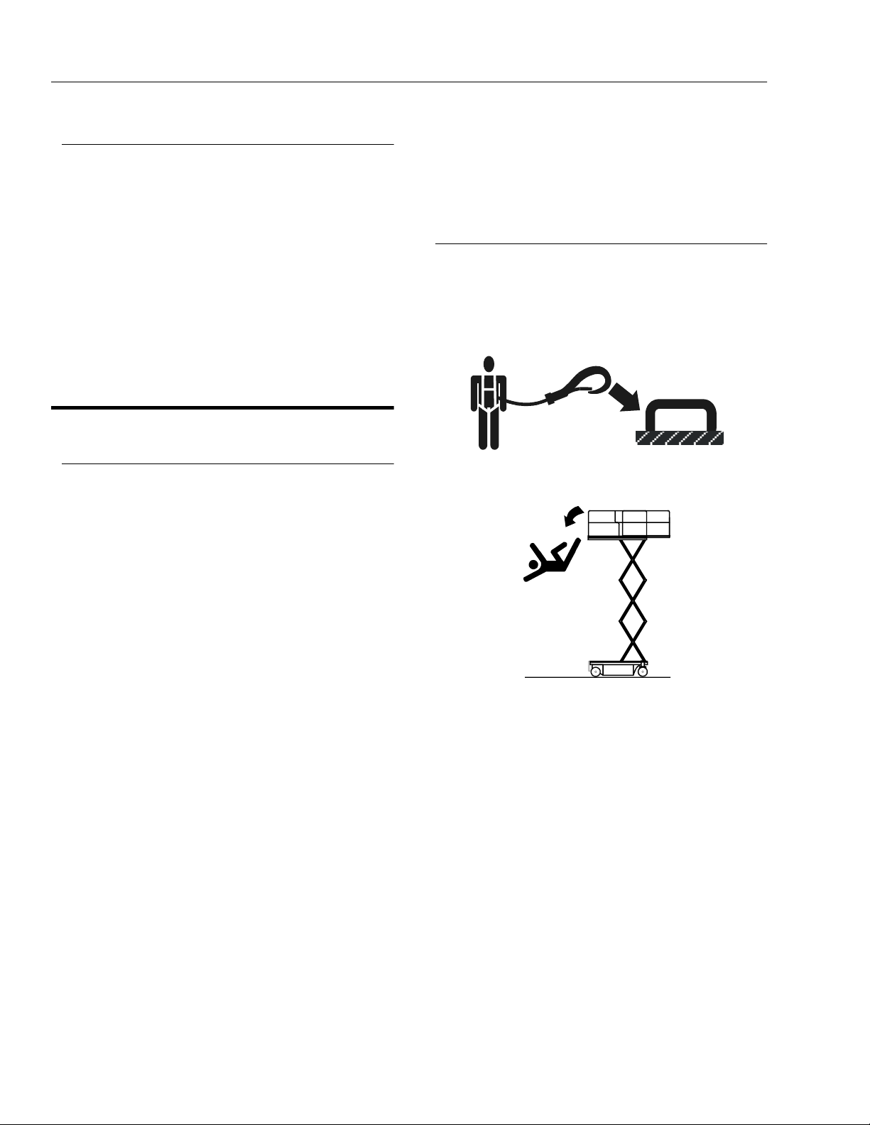
Trip and Fall Hazards
• When operating a boom lift, occupants in the platform
must wear a full body harness with a lanyard attached
to an authorized lanyard anchorage point. When operating a scissor lift or vertical mast lift, JLG recommends
wearing a full body harness. Attach only one (1) lanyard per lanyard anchorage point.
• Before operating the machine, make sure all gates are
closed and fastened or in their proper position.
• Keep both feet firmly positioned on the platform floor at
all times. Never use ladders, boxes, steps, planks, or
similar items on platform to provide additional reach.
• Never use the elevating assembly to enter or leave the
platform.
• Use extreme caution when entering or leaving platform. Be sure that the platform is fully lowered. Face
the machine, maintain “three point contact” with the
machine, using two hands and one foot or two feet and
one hand during entry and exit.
• Check orientation of directional arrows on chassis
before driving. The direction of drive and steer may be
opposite from normal operation based upon orientation of chassis.
1-2 – JLG Lift – 3120690
SECTION 1 - SAFETY PRECAUTIONS
• Platform-to-structure transfers at elevated positions are
discouraged. Where transfer is necessary, enter/exit
through the gate only with the platform within 1 foot
(0.3m) of a safe and secure structure. 100% tie-off is
also required in this situation using two lanyards. One
lanyard must be attached to the platform with the second lanyard attached to the structure. The lanyard connected to the platform must not be disconnected until
the transfer to the structure is safe and complete.
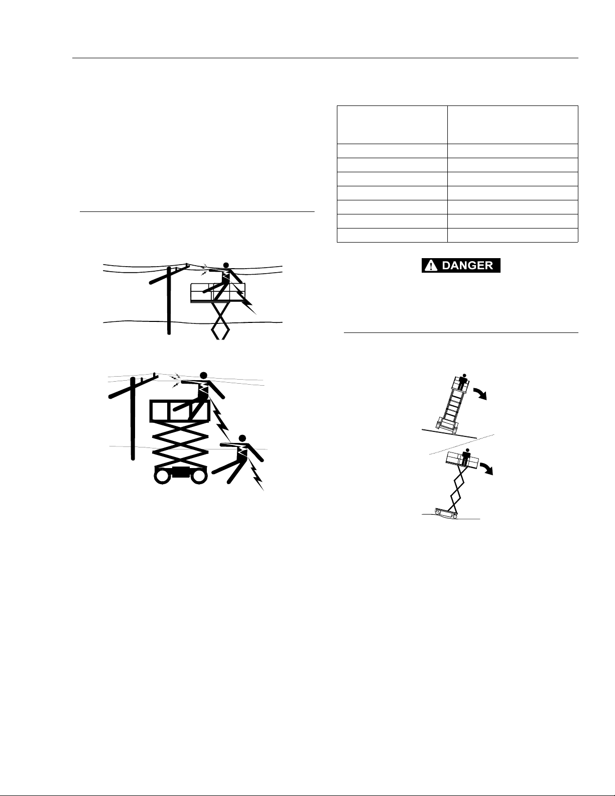
Electrocution Hazards
• This machine is not insulated and does not provide
protection from contact or proximity to electrical current.
Table 1-1.Minimum Safe Approach Distances (M.S.A.D.)
Voltage Range
(Phase to Phase)
0 to 300V AVOID CONTACT
Over 300V to 50 KV 3 (10)
Over 50KV to 200 KV 5 (15)
Over 200 KV to 350 KV 6(20)
Over 350 KV to 500 KV 8 (25)
Over 500 KV to 750 KV 11 (35)
Over 750 KV to 1000 KV 14 (45)
DO NOT MANEUVER MACHINE OR PERSONNEL INSIDE PROHIBITED ZONE (MSAD). ASSUME ALL ELECTRICAL PARTS AND WIRING ARE ENERGIZED UNLESS KNOWN OTHERWISE.
MINIMUM SAFE APPROACH
DISTANCE
in Meters (Feet)
Tipping Hazards
• The user should be familiar with the surface before
driving. Do not exceed the allowable sideslope and
grade while driving..
• Maintain safe distance from electrical lines, apparatus,
or any energized (exposed or insulated) parts according to the Minimum Safe Approach Distance (MSAD)
as shown in Table 1-1.
• Allow for machine movement and electrical line swaying.
• Do not elevate platform or drive with platform elevated
while on a sloping, uneven, or soft surface.
• Before driving on floors, bridges, trucks, and other surfaces, check allowable capacity of the surfaces.
• Never exceed the maximum platform capacity. Distribute loads evenly on platform floor.
3120690 – JLG Lift – 1-3
SECTION 1 - SAFETY PRECAUTIONS
• Do not raise the platform or drive from an elevated
position unless the machine is on firm, level surfaces
and evenly supported.
• Keep the chassis of the machine at least 2 ft. (0.6m)
from holes, bumps, drop-offs, obstructions, debris,
concealed holes, and other potential hazards on the
floor/surface unless approved by JLG.
• Never attempt to use the machine as a crane. Do not
tie-off machine to any adjacent structure.
• Do not operate the machine when wind conditions
exceed the maximum allowable wind speed.
• Do not increase the surface area of the platform or the
load. Increase of the area exposed to the wind will
decrease stability.
• Do not increase the platform size with unauthorized
deck extensions or attachments.
• If elevating assembly or platform is in a position that
one or more wheels are off the ground, all persons
must be removed before attempting to stabilize the
machine. Use cranes, forklift trucks, or other appropriate equipment to stabilize machine and remove personnel.
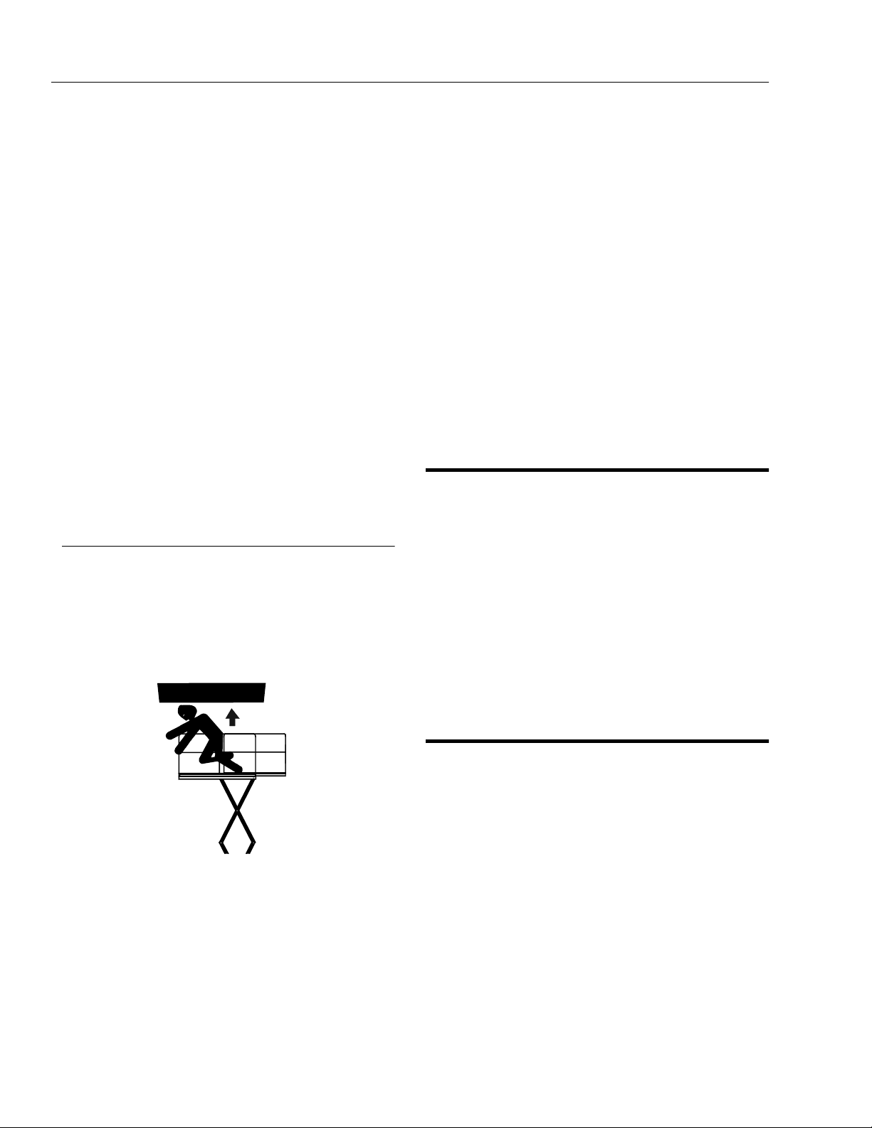
Crushing and Collision Hazards
• Approved head gear must be worn by all operating
and ground personnel.
• Keep hands and limbs out of the elevating assembly
during operation.
• Check work area for clearances overhead, on sides,
and bottom of platform when lifting or lowering platform, and driving.
• Limit travel speed according to conditions of ground
surface, congestion, visibility, slope, location of personnel, and other factors which may cause collision or
injury to personnel.
• Be aware of stopping distances in all drive speeds.
When driving in high speed, switch to low speed
before stopping. Travel grades in low speed only.
• Do not use high speed drive in restricted or close quarters or when driving in reverse.
• Exercise extreme caution at all times to prevent obstacles from striking or interfering with operating controls
and persons in the platform.
• Be sure that operators of other overhead and floor level
machines are aware of the aerial work platform’s presence. Disconnect power to overhead cranes.
• Warn personnel not to work, stand, or walk under a
raised platform. Position barricades on floor if necessary.
1.4 TOWING, LIFTING, AND HAULING
• Never allow personnel in platform while towing, lifting,
or hauling.
• This machine should not be towed, except in the event
of emergency, malfunction, power failure, or loading/
unloading. Refer to the Emergency Procedures section
of this manual for emergency towing procedures.
• The platform must be completely empty of tools.
• When lifting machine, lift only at designated areas of
the machine. Lift with lifting equipment of adequate
capacity.
• Refer to the Machine Operation section of this manual
for lifting information.
1.5 ADDITIONAL HAZARDS / SAFETY
• Do not use machine as a ground for welding.
• Do not refuel the machine with the engine running.
• Battery fluid is highly corrosive. Avoid contact with skin
and clothing at all times.
• Charge batteries only in a well ventilated area.
• During operation, keep all body parts inside platform
railing.
• Use elevating assembly functions, not the drive function to position the platform close to obstacles
• Always post a lookout when driving in areas where
vision is obstructed.
• Keep non-operating personnel at least 1.8m (6 ft.)
away from machine during all driving operations.
1-4 – JLG Lift – 3120690

SECTION 2 - PREPARATION AND INSPECTION
SECTION 2. PREPARATION AND INSPECTION
2.1 GENERAL
This section provides the necessary information needed
by those personnel that are responsible to place the
machine in operation readiness, and lists checks that are
performed prior to use of the machine. It is important that
the information contained in this section be read and
understood before any attempt is made to operate the
machine. Ensure that all the necessary inspections have
been completed successfully before placing the machine
into service. These procedures will aid in obtaining maximum service life and safe operation.
IM P ORTANT
SINCE THE MACHINE MANUFACTURER HAS NO DIRECT CONTROL OVER THE FIELD INSPECTION AND MAINTENANCE,
SAFETY IS THE RESPONSIBILITY OF THE OWNER/OPERATOR.
2.2 PREPARATION FOR USE
1. Before a new machine is put into operation it must
be carefully inspected for any evidence of damage
resulting from shipment and inspected periodically
thereafter, as outlined in paragraph 2-3, Delivery and
Periodic Inspection. The unit should be thoroughly
checked for hydraulic leaks during initial start-up
and run. A check of all components should be made
to assure their security.
2.3 DELIVERY AND PERIODIC INSPECTION
NOTE: This machine requires periodic safety and mainte-
nance inspections by a JLG Dealer. A decal on the
frame provides a place to record (stamp) inspection
dates. Check decal and notify dealer if inspection is
overdue.
An annual inspection shall be performed on the
aerial platform no later than thirteen (13) months
from the date of the prior annual inspection. The
inspection shall be perfor med by person( s) certified
as a mechanic on the specific make and model of
the aerial platform.
The following checklist provides a systematic inspection
to assist in detecting defective, damaged, or improperly
installed parts. The checklist denotes the items to be
inspected and conditions to examine.
Frequent inspection shall be performed every 3 months or
150 hours whichever comes first, or more often when
required by environment, severity, and frequency of
usage.
Handrail Assemblies
Properly installed; no loose or missing parts; no visible
damage.
Platform Assembly
No visible damage; free of dirt and debris.
2. All preparations necessary to place the machine in
operation readiness status are the responsibility of
management personnel. Preparation requires good
common sense, (i.e. lift works smoothly and brakes
operate properly) coupled with a series of visual
inspections. The mandatory requirements are given
in paragraph 2-4, Daily Walk Around Inspection.
Sizzor Arms
No visible damage, abrasions and/or distortions.
Electrical Cable
No visible damage; properly secured.
Pivot Pins
3. It should be assured that the items appearing in the
Delivery and Periodic Inspection and Functional
Check are complied with prior to putting the
machine into service.
No loose or missing retaining hardware; no damage or
wear to pin heads which would cause pin to rotate; no evidence of pin or bushing wear.
Lift Cylinder
No rust, nicks, scratches or foreign material on piston rod.
No leakage. Evidence of proper lubrication.
3120690 – JLG Sizzor – 2-1

SECTION 2 - PREPARATION AND INSPECTION
Frame
No visible damage; loose or missing hardware (top and
underside).
Drive Hubs
Check oil level in drive hub by removing pipe plug and
feeling for oil level. (Contact service personnel for assistance if needed.)
NOTE: Torque Hubs should be one-half full of lubricant.
Tire and Wheel Assemblies
No loose or missing lug nuts; no visible damage.
Sliding Wear Pad Blocks
No excessive wear; adequate lubrication.
Hydraulic Oil Supply
Operate hydraulic systems through one complete cycle
before checking oil level in hydraulic oil tank. Oil should
be visible in ADD sight window on hydraulic oil tank. If oil
is not visible, add oil until oil is visible in both ADD and
FULL sight windows on tank. Do not overfill tank.
Steer Cylinder
No rust, nicks, scratches or foreign material on piston rod;
no leakage.
Steer Linkage
No loose or missing parts; no visible damage.
Steer Spindle Assemblies
No excessive wear; no damage.
Control Boxes (Console and Ground)
Switches operable; no visible damage; placards secure
and legible. Hand controller operable; no visible damage.
Battery
Proper electrolyte level; cable connections tight; no visible
damage; no corrosion at battery cable connections.
Engine
Engine oil level - full mark on dipstick; filler cap secure; air
filter secure.
Hydraulic Pump and Valves
No visible damage; no evidence of leakage; units secure.
Platform Placards
No visible damage; placards secure and legible.
Lock-Out Cylinders (If Equipped)
No rust, nicks, scratches or foreign material on piston rod;
no leakage.
2-2 – JLG Sizzor – 3120690

SECTION 2 - PREPARATION AND INSPECTION
2.4 DAILY WALK-AROUND INSPECTION
It is the users responsibility to inspect the machine before
the start of each workday. It is recommended that each
user inspect the machine before operation, even if the
machine has already been put into service under another
user. This Daily Walk-Around Inspection is the preferred
method of inspection.
In addition to the Daily Walk-Around Inspection, be sure to
include the following as part of the daily inspection:
Overall Cleanliness
Check all standing surfaces for oil, fuel and hydraulic oil
spillage and foreign objects. Ensure overall cleanliness.
Placards
Keep all information and operating placards clean and
unobstructed. Cover when spray painting or shot blasting
to protect legibility.
Operators and Safety Manual
Ensure a copy of this manual is enclosed in the manual
storage box.
Machine Log
Ensure a machine operating record or log is kept. Check
to see that it is current and that no entries have been left
uncleared, leaving machine in an unsafe condition for
operation.
Daily Lubrication
For those items pointed out in the Daily Walk-Around
Inspection requiring daily lubrication Refer to Table 2-1,
Lubrication Chart, for specific requirements.
Perform the following checks and services before attempting to operate the machine.
TO AVOID INJURY DO NOT OPERATE A MACHINE UNTIL ALL
MALFUNCTIONS HAVE BEEN CORRECTED. USE OF A MALFUNCTIONING MACHINE IS A SAFETY VIOLATION.
1. Start each day with a full fuel tank. If operating an
electric machine, start each day with fully charged
batteries.
2. Ensure that all items requiring lubrication are serviced in accordance with the Lubrication Chart.
Refer to Table 2-1, Lubrication Chart.
3. Perform functional checks in accordance with paragraph 2-5, Daily Functional Check.
3120690 – JLG Sizzor – 2-3

SECTION 2 - PREPARATION AND INSPECTION
Figure 2-1. Walk-Around Inspection Diagram
2-4 – JLG Sizzor – 3120690

SECTION 2 - PREPARATION AND INSPECTION
GENERAL
Begin the “Walk-Around Inspection” at Item 1, as noted
on the diagram.Continue to the right (counterclockwise
viewed from top) checking each item in sequence for the
conditions listed in the “Walk-Around Inspection Checklist”.
TO AVOID INJURY DO NOT OPERATE MACHINE UNTIL ALL MALFUNCTIONS HAVE BEEN CORRECTED. USE OF A MALFUNCTIONING MACHINE IS A SAFETY VIOLATION. TO AVOID
POSSIBLE INJURY, BE SURE MACHINE POWER IS “OFF” DURING “WALK-AROUND INSPECTION”.
NOTE: Do not overlook visual inspection of chassis under-
side. Checking thi s area o ften res ults in discovery of
conditions which could cause extensive machine
damage.
1. Steer Cylinder and Tie Rod Ends - No loose or
missing parts, no visible damage. No steer cylinder
leaks or damage.
2. Leveling Jack, Left Front (If Equipped) - No loose or
missing parts, no visible damage. No cylinder leaks
or damage.
3. Steer Spindle, Left Front - No loose or missing
parts, no visible damage, evidence of proper lubrication.
4. Drive Motor, Left Front (4 Wheel Drive) - No visible
damage, no evidence of leakage.
5. Drive Brake, Left Front (4 Wheel Drive) - No loose or
missing parts, no visible damage, no evidence of
leakage.
6. Drive Hub, Left Front (4 Wheel Drive) - No visible
damage, no evidence of leakage. Drive hubs
should be one half full of EPGL SAE 90.
7. Steer/Drive Wheel and Tire Assembly, Left Front Properly secured, no loose or missing lug nuts, no
visible damage. Refer to inflation psi stenciled on
frame.
8. Oscillating Axle (If Equipped) - Properly secured,
evidence of proper lubrication. No lockout cylinder
leaks or damage.
9. Ground Controls - Switches operable, no visible
damage, placards secure and legible.
10. Hydraulic Reservoir - No visible damage or missing
parts. No evidence of leaks. Recommended oil level
in sight glass. Breather cap secure and working.
11. Hydraulic Filter - No visible damage, properly
secured, no evidence of leakage.
12. Control Valves - Valves properly secured, no visible
damage, no evidence of leakage. Hoses and fittings
properly secured, no visible damage, no evidence
of leaks.
13. Tilt Alarm Switch - Properly secured, no loose or
missing parts, no visible damage.
14. Fuel Tank - Filler cap secure, sight gauge visible, no
damage or leaks.
15. Safety Prop - Stored securely, no missing parts.
16. Travel/Descent/Motion Alarm - Properly secured, no
loose or missing parts, no visible damage.
17. Drive Motor, Left Rear - No visible damage, no evidence of leakage.
18. Drive Brake, Left Rear - No loose or missing parts,
no visible damage, no evidence of leakage.
19. Drive Hub, Left Rear - No visible damage, no evidence of leakage. Drive hubs should be one half full
of EPGL SAE 90.
20. Drive Wheel and Tire Assembly, Left Rear - Properly
secured, no loose or missing lug nuts, no visible
damage. Refer to inflation psi stenciled on frame or
wheel rims.
21. Steer Spindle, Left Rear (If Equipped) - No loose or
missing parts, no visible damage, evidence of
proper lubrication.
22. Leveling Jack, Left Rear (If Equipped) - No loose or
missing parts, no visible damage. No cylinder leaks
or damage.
23. Battery Installation (Gasoline or Diesel Engine) Proper electrolyte level, cables secure, no damage
or corrosion. Hold-downs secure.
24. Ladder - No damage, securely attached.
25. Leveling Jack, Right Rear (If Equipped) - No loose
or missing parts, no visible damage. No cylinder
leaks or damage.
26. Rear Steer Cylinder and Tie Rod Ends (If Equipped)
- No loose or missing parts, no visible damage. No
steer cylinder leaks or damage.
27. Steer Spindle, Right Rear (If Equipped) - No loose
or missing parts, no visible damage, evidence of
proper lubrication.
Figure 2-2. Walk-Around Inspection Points (Sheet 1 of 2)
3120690 – JLG Sizzor – 2-5

SECTION 2 - PREPARATION AND INSPECTION
28. Drive Motor, Right Rear - No visible damage, no evidence of leakage.
29. Drive Brake, Right Rear - No loose or missing parts,
no visible damage, no evidence of leakage.
30. Drive Hub, Right Rear - No visible damage, no evidence of leakage. Drive hubs should be one half full
of EPGL SAE 90.
31. Drive Wheel and Tire Assembly, Left Rear - Properly
secured no loose or missing lug nuts, no visible
damage. Refer to inflation psi stenciled on frame or
wheel rims.
32. Sizzor Arms and Sliding Wear Pads - Properly
secured, no visible damage, evidence of proper
lubrication. Inspect sizzor arm guards for damage
and proper installation.
33. Lift Cylinder - Properly secured, no visible damage,
no loose or missing parts, no evidence leakage.
34. Safety Prop - Stored securely, no missing parts.
35. Hydraulic Pump - Pump properly secured, no visible damage, no evidence of leakage. Hoses and fittings properly secured, no visible damage, no
evidence of leaks.
36. Engine Installation - Engine oil to full mark on dipstick, oil fillercap secure. Muffler/exhaust system
properly secured, no leakage. Air filter assembly
secure, no loose or missing parts, element clean.
Gasoline Engine Only - Radiator cap secure, coolant to correct level.
38. Steer/Drive Wheel and Tire Assembly, Right Front Properly secured, no loose or missing lug nuts, no
visible damage. Refer to inflation psi stenciled on
frame or wheel rims.
39. Drive Motor, Right Front (4 Wheel Drive) - No visible
damage, no evidence of leakage.
40. Drive Brake, Right Front (4 Wheel Drive) - No loose
or missing parts, no visible damage, no evidence of
leakage.
41. Drive Hub, Right Front (4 Wheel Drive) - No visible
damage, no evidence of leakage. Drive hubs
should be one half full of EPGL SAE 90.
42. Steer Spindle, Right Front - No loose or missing
parts, no visible damage, evidence of proper lubrication.
43. Leveling Jack, Right Front (If Equipped) - No loose
or missing parts, no visible damage. No cylinder
leaks or damage.
44. Drive and Lift Cutout Switches (If Equipped) - No
visible damage, properly secured.
45. Platform Controls - Properly secured, no loose or
missing parts, no visible damage. Placards secure
and legible, control switches return to neutral. Control markings legible, manual in manual storage
box.
46. Manual Descent Cable - Properly secured, no loose
or missing parts, no visible damage.
37. Handrail installation - All railings securely attached,
no damage or missing parts, chains securely
attached.
Figure 2-3. Walk-Around Inspection Points (Sheet 2 of 2)
2-6 – JLG Sizzor – 3120690

SECTION 2 - PREPARATION AND INSPECTION
2.5 DAILY FUNCTIONAL CHECK
TO AVOID SERIOUS INJURY, DO NOT OPERATE MACHINE IF ANY
CONTROL LEVERS OR TOGGLE SWITCHES CONTROLLING
PLATFORM MOVEMENT DO NOT RETURN TO THE OFF POSITION
WHEN RELEASED.
A functional check of all systems should be performed,
under no load, once the walk-around inspection is complete, in an area free of overhead and ground level
obstructions. Perform pre-load functional check in accordance with the following procedure:
1. Raise and lower platform several times. Check for
smooth elevation and lowering. Check that high
function speeds cut out at 6 in. (15.2 cm) above fully
retracted platform height.
2. Drive forward and reverse, check for proper operation.
3. Check that drive brakes hold when machine is
driven up a hill, not to exceed rated gradeability, and
stopped.
4. Steer left and right. Check for proper operation.
2.6 LOCK-OUT CYLINDER CHECK - (IF EQUIPPED)
To be performed quarterly, any time a system component
is replaced, or when improper system operation is suspected on machines with oscillating axles.
NOTE: Ensure platform is fully lowered prior to beginning
lockout cylinder check.
1. Place an 8 in (20 cm) high block with ascension
ramp in front of the left front wheel.
2. Activate the machines hydraulic system from the
platform control station.
3. Place the engine speed and drive speed control
switches to their respective low positions.
4. Place the drive controller to the forward position and
carefully drive the machine up the ascension ramp
until the left front wheel is on top of the block.
5. Raise the machine platform approximately 24 in. (61
cm.); ensure the lockout cylinder cam valve is free of
the sizzor arm trip bar.
6. Place the drive controller to the reverse position and
carefully drive the machine off of the block and
ramp.
7. Have an assistant check to see that the left front
wheel remains locked in position off of the ground.
5. Check hydraulic oil reservoir sight gauge. Refer to
Lubrication Chart.
TO AVOID INJURY DO NOT OPERATE A MACHINE UNTIL ALL
MALFUNCTIONS HAVE BEEN CORRECTED. USE OF A MALFUNCTIONING MACHINE IS A SAFETY VIOLATION.
8. Lower the machine platform; the lockout cylinder
should then release the wheel and allow it to rest on
the ground.
9. If the lockout cylinder does not function properly,
have qualified personnel correct the malfunction
prior to any further operation.
3120690 – JLG Sizzor – 2-7

SECTION 2 - PREPARATION AND INSPECTION
Figure 2-4. Lubrication Diagram
2-8 – JLG Sizzor – 3120690

SECTION 2 - PREPARATION AND INSPECTION
Table 2-1. Lubrication Chart
INDEX
NO
1 Oscillating Axle Pivot Point (Optional) 1 Grease Fitting MPG - Pressure Gun 100
2 Lockout Cylinders (Optional) 2 Grease Fittin gs (1 each cylinder) MPG - Pressure Gun 100
3 Front Steering Spindles (2-W/D) 2 Grease Fittings MPG - Pressure Gun 100
4 Front Steering Spindles (4-W /D)
5 Tow B ar Hitch (Optional) 1 Grease Fitting MPG - Pressure Gun 100
6 Wheel Bearings (2-W/D) N/A MPG - Repack 2000
7 *Whe el Drive Hub (4-W/D) (Optional) Fill Plug EPGL (SAE 90) 500
8 Engine Crankcase Fill Ca p/Drain Plug Check Engine Oil Level 10/100
9 Lift Cylinder 2 Grease Fittings MPG - Pressure Gun 100
10 *Wheel Drive Hub Fill Plug EPGL (SAE 90) 500
11 Rear Steering Spind les (4-W/S)
12 Rail Slid es N/A MPG - Brush 100
13 Hydraulic Oil Rese rvoir Fill Cap/Drain Plu g HO - Check HO Level (See note 4)/
14 ** Hydraulic Filter Element N/A Initial Change - 40 Ho urs 250
COMPONENT NUMBER/TYPE LUBE POINTS LUBE METHOD
2 Grease Fittings MPG - Pressure Gun 100
(Optional)
2 Grease Fittings MPG - Pressure Gun 100
(Optional)
HO - Change HO
INTERVAL
HOURS
10/500
*Torque Hubs should be 1/2 full of lubricant
** JLG Industries recommends replacing the hydraulic
filter after the first 40 hours of operation and every 250
hours thereafter.
KEY TO LUBRICANTS:
MPG - Multi-purpose Grease
EPGL - Extreme Pressure Gear Lube
HO - Hydraulic Oil (Mobil 424)
TO AVOID PERSONAL INJURY, USE SAFETY PROP FOR ALL
MAINTENANCE REQUIRING PLATFORM TO BE ELEVATED.
NOTE: 1. Be sure to lubricate like items on each side
2. Recommended lubricating intervals are based
on machine operations under normal conditions.
For machines used in multi-shift operations and/or
exposed to hostile environments or conditions,
lubrication frequencies must be increased accordingly.
3. Operate hydraulic functions through one complete cycle before checking hydraulic oil level in
tank. Oil shoul d be vis ibl e in A DD sigh t wi ndow on
hydraulic tank. If oil is not visible, add oil until oil is
visible in both ADD and FULL sight windows on
tank. Do not overfill tank.
4. Any time the pump coupling is removed, coat
splines of coupling with Texaco Code 1912 grease
prior to assembly. (gasoline or diesel engine only).
3120690 – JLG Sizzor – 2-9

SECTION 2 - PREPARATION AND INSPECTION
2.7 DUAL FUEL SYSTEM
IT IS POSSIBLE TO SWITCH FROM ONE FUEL SOURCE TO THE
OTHER WITHOUT ALLOWING THE ENGINE TO STOP. EXTREME
CARE MUST BE TAKEN AND THE FOLLOWING INSTRUCTIONS
MUST BE FOLLOWED.
Changing from Gasoline to LP Gas
1. Start the engine from the ground control station.
2. Open the hand valve on the LP Gas supply tank by
turning counterclockwise.
BE SURE ALL GASOLINE IS EXHAUSTED BEFORE SWITCHING
TO LP GAS.
3. While the engine is operating, place the three position LPG/GAS SELECT switch at the ground control
station to the center OFF position. Allow the engine
to operate, without load, until the engine begins to
stumble from lack of gasoline.
4. As the engine begins to stumble place the switch to
the LPG position, allowing the LP fuel to be sent to
the fuel regulator.
Changing from LP Gas to Gasoline
1. With engine operating on LP under a no-load condition, position the LPG/GAS SELECT switch at
ground control to the GAS SELECT position.
2. If engine stumbles because of lack of gasoline,
place the switch to the LPG position until engine
regains smoothness, then return the switch to the
GAS SELECT position. Repeat as necessary until
engine runs smoothly on gasoline.
3. Close the hand valve on the LP gas supply tank by
turning clockwise.
2.8 TORQUE REQUIREMENTS
The Torque Chart, Figure 2-3, consists of standard torque
values based on bolt diameter and grade, also specifying
dry and wet torque values in accordance with recommended shop practices. This chart is provided as an aid
to the operator in the event he/she notices a condition that
requires prompt attention during the walk-around inspection or during operation until the proper service personnel
can be notified. Section 1 of the Service and Maintenance
Manual provides specific torque values and periodic
maintenance procedures with a listing of individual components. Utilizing this Torque Chart in conjunction with the
preventive maintenance section in Section 2 of the Service
and Maintenance Manual, will enhance safety, reliability
and performance of the machine.
2-10 – JLG Sizzor – 3120690

SECTION 2 - PREPARATION AND INSPECTION
Figure 2-5. Torque Chart
3120690 – JLG Sizzor – 2-11

SECTION 2 - PREPARATION AND INSPECTION
This page intentionally left blank.
2-12 – JLG Sizzor – 3120690

SECTION 3 - USER RESPONSIBILITIES AND MACHINE CONTROL
SECTION 3. USER RESPONSIBILITIES AND MACHINE CONTROL
3.1 GENERAL
IM P ORTAN T
SINCE THE MANUFACTURER HAS NO DIRECT CONTROL OVER
MACHINE APPLICATION AND OPERATION, CONFORMANCE
WITH GOOD SAFETY PRACTICES IN THESE AREAS IS THE
RESPONSIBILITY OF THE USER AND HIS OPERATING PERSONNEL.
This section provides the necessary information needed
to understand control functions. Included in this section
are the operating characteristics and limitations, and functions and purposes of controls and indicators. It is important that the user read and understand the proper
procedures before operating the machine. These procedures will aid in obtaining optimum service life and safe
operation.
3.2 PERSONNEL TRAINING
The sizzor lift is a personnel handling device; therefore, it
is essential that it be operated and maintained only by
authorized personnel who have demonstrated that they
understand the proper use and maintenance of the
machine. It is important that all personnel who are
assigned to and responsible for the operation and maintenance of the machine undergo a thorough training program and check out period in order to become familiar
with the characteristics prior to operating the machine.
3. Knowledge and understanding of all safety work
rules of the employer and of Federal, State and
Local Statutes, including training in the recognition
and avoidance of potential hazards in the work
place; with particular attention to the work to be performed.
4. Proper use of all required personnel safety equipment.
5. Sufficient knowledge of the mechanical operation of
the machine to recognize a malfunction or potential
malfunction.
6. The safest means to operate near overhead obstructions, other moving equipment, obstacles, depressions, holes, dropoffs, etc. on the supporting
surface.
7. Means to avoid the hazards of unprotected electrical
conductors.
8. Any other requirements of a specific job or machine
application.
Tra inin g S upe rvi s io n
Training must be done under the supervision of a qualified
operator or supervisor in an open area free of obstructions
until the trainee has developed the ability to safely control
a sizzor lift in congested work locations.
In addition, personnel operating the machine should be
familiar with ANSI standard A92.6-1999 Responsibilities.
This standard contains sections outlining the responsibilities of the owners, users, operators, lessors and lessees
concerning safety, training, inspection, maintenance,
application and operation.
Persons under the influence of drugs or alcohol or who
are subject to seizures, dizziness or loss of physical control must not be permitted to operate the machine.
Operator Training
Operator training must include instruction in the following:
1. Use and limitations of the platform controls, ground
controls, emergency controls and safety systems.
2. Knowledge and understanding of this manual and of
the control markings, instructions and warnings on
the machine itself.
Operator Responsibility
The operator must be instructed that he has the responsibility and authority to shut down the machine in case of a
malfunction or other unsafe condition of either the
machine or the job site and to request further information
from his supervisor or JLG Distributor before proceeding.
NOTE: Manufacturer or Distributor will provide qualified per-
sons for training assistance with first unit(s) delivered and thereafter as requested by user or his
personnel.
3.3 OPERATING CHARACTERISTICS AND LIMITATIONS
General
A thorough knowledge of the operating characteristics
and limitations of the machine is always the first requirement for any user, regardless of user’s experience with
similar types of equipment.
3120690 – JLG Sizzor – 3-1

SECTION 3 - USER RESPONSIBILITIES AND MACHINE CONTROL
Placards
Important points to remember during operation are provided at the control stations by DANGER, WARNING,
CAUTION, IMPORTANT and INSTRUCTION placards. This
information is placed at various locations for the express
purpose of alerting personnel of potential hazards constituted by the operating characteristics and load limitations
of the machine. See foreword for definitions of the above
placards.
Capacities
Raising platform above horizontal with or without any load
in platform, is based on the following criteria:
1. Machine is positioned on a smooth, firm and level
surface.
2. Load is within manufacturer’s rated capacity.
3. All machine systems are functioning properly.
Stability
This machine, as originally manufactured by JLG and
operated within its rated capacity on a smooth, firm and
level supporting surface, provides a stable aerial platform
for all platform positions.
3.4 CONTROLS AND INDICATORS
Some machines may be equipped with control panels that
use symbols instead of words to indicate control functions. Refer to Figure 3-3., Decal Installation for these symbols and their corresponding functions.
IM P ORTAN T
RTS SERIES SCISSOR LIFTS MANUFACTURED AFTER AUGUST
26, 1996 ARE EQUIPPED WITH A HYDRAULIC OIL TEMPERATURE
SWITCH THAT SHUTS DOWN THE ENGINE WHEN THE HYDRAULIC OIL REACHES A TEMPERATURE OF APPROXIMATELY 230
DEGREES F (111 DEGREES C). THIS SHUT DOWN IS INTENDED
TO PROTECT THE HYDRAULIC SYSTEM AND ITS COMPONENTS
FROM DAMAGE DUE TO EXCESSIVE HEAT. HEAT MAY BUILD UP
DUE TO EXTENDED DRIVING, IN CONJUNCTION WITH HIGH
AMBIENT TEMPERATURES, ACTIVATING THIS SWITCH AND
SHUTTING DOWN THE MACHINE. IF THE MACHINE SHUTS
DOWN, ALLOW THE HYDRAULIC OIL TO COOL, THEN RESUME
NORMAL OPERATION.
Ground Control Station
DO NOT OPERATE FROM GROUND CONTROL STATION WITH
PERSONNEL IN THE PLATFORM EXCEPT IN AN EMERGENCY.
PERFORM AS MANY PRE-OPERATIONAL CHECKS AND INSPECTIONS FROM THE GROUND CONTROL STATION AS POSSIBLE.
1. Ignition/Emergency Stop - A two-position, red
mushroom shaped switch supplies electrical power
to the Start button when positioned up. When positioned down, the switch shuts off electrical power to
the ignition circuit, acting as an emergency stop
switch.
NOTE: With the Main Power switch in the off position, the
key can be removed in order to incapacitate the
machine on the jobsite to avoid unauthorized use of
the machine.
2. Platform/Ground Select Switch - A three position
Platform/Ground Select switch supplies operating
power to the platform or ground controls, as
selected. When positioned to platform, the switch
provides power to the platform controls. When positioned to ground, the switch provides power to the
ground controls. With the power selector switch in
the center off position, power is shut off to both platform and ground controls.
NOTE: With the Platform/Grou nd Select switch pos iti one d to
ground, engine speed will stay in low at all times.
3. Start Button - A momentary contact, push-button-
type switch that supplies electrical power to the
starter solenoid when the ignition/emergency stop
switch is in the on position and the start button is
depressed.
4. Lift Switch - A three position, momentary contact lift
control switch provides raising and lowering of the
platform when positioned to up or down.
5. High Engine Circuit Breaker (Diesel Engine) - A
push button reset 3 Amp circuit breaker, located at
the ground control panel, returns interrupted power
to the machine functions when depressed.
3-2 – JLG Sizzor – 3120690

SECTION 3 - USER RESPONSIBILITIES AND MACHINE CONTROL
Figure 3-1. Ground Control Station
6. Choke Switch - (If Equipped) - A momentary con-
tact, push-button type switch supplies power to the
choke solenoid, when depressed, to assist cold start
operation.
7. Gasoline/LPG Select Switch - (Dual Fuel Only) -
A three position toggle-type switch is used to select
the desired method of powering the unit. Placing the
switch in the gasoline position shuts off the fuel flow
from the LP gas supply tank and allows fuel flow
from the gasoline tank. Moving the switch to the LPG
position shuts off fuel flow from the gasoline tank
and allows LP gas from supply tank to be used to
power the unit. With the switch in the center position, fuel flow is restricted from both supply tanks.
8. Hourmeter - The hourmeter records engine or elec-
tric motor operating time.
9. Voltmeter - With the emergency stop switch in the
up position, and before starting the engine, the voltmeter indicates output voltage of the alternator. Normal reading for the voltmeter will be 12-14 volts with
a properly charged or charging battery.
10. Water Temperature Gauge - (Gasoline Engine) -
The water temperature gauge provides a visual display of the engine coolant temperature.
11. Oil Pressure Gauge - The oil pressure gauge dis-
plays the engine lubrication system operating pressure.
3120690 – JLG Sizzor – 3-3

SECTION 3 - USER RESPONSIBILITIES AND MACHINE CONTROL
Figure 3-2. Platform Control Station
Platform Control Station
1. Enable Switch -These machines are equipped with
an enable switch on the side of the platform control
console. On machines built with a serial number
before 0200058922, the enable switch must be
pressed before activating the drive, lift or steer functions. A built-in timer shuts off power to these functions if they are not activated within 3 seconds after
the enable switch is depressed. In addition, this
timer will shut off power to the drive and lift functions
3 seconds after they are deactivated, making if necessary to depress the enable switch before activating drive and lift again. The steer function, unless
activated in conjunction with the drive or lift functions, will automatically cut off after 3 seconds of
operation. On machines built from, and including,
serial number 0200058922, the enable switch must
be depressed and held for the duration of lift. The
enable switch works in conjunction with the lift
switch only.
2. Ignition/Emergency Stop Switch - A red ignition/
emergency stop mushroom-type switch is provided
in order to turn on machine power in the platform
and also to turn off machine power in the event of an
emergency. Power is turned on by positioning the
switch to the up (on) position, and is turned off by
positioning the switch to the down (off) position.
3. Start Button - A momentary contact, push-button-
type switch that supplies electrical power to the
starter solenoid when the ignition/emergency stop
switch is in the on position and the start button is
depressed.
3-4 – JLG Sizzor – 3120690

SECTION 3 - USER RESPONSIBILITIES AND MACHINE CONTROL
4. Tilt Alarm Warning Horn - The Tilt Alarm Warning
Horn is activated by the tilt alarm switch when the
chassis is on a severe slope (over 3°) with the platform raised.
IF TILT ALARM IS ON WHEN PLATFORM IS RAISED, LOWER
PLATFORM COMPLETELY, THEN REPOSITION MACHINE SO
THAT IT IS LEVEL BEFORE RAISING PLATFORM.
5. Tilt Alarm Warning Light - A warning light on the
control console that lights when the chassis is on a
severe slope (over 3 °).
NOTE: The lift toggle switch automatically returns to the
center off position when released.
TO AVOID SERIOUS INJURY, DO NOT OPERATE MACHINE IF LIFT
TOGGLE SWITCH DOES NOT RETURN TO THE CENTER OFF
POSITION WHEN RELEASED.
6. Lift Switch - The lift toggle switch provides for rais-
ing and lowering the platform when positioned to up
or down.
7. Engine Speed Switch - A two position engine
speed control switch provides the operator either
high or low engine rpm as required.
8. Pump Speed Switch - A two position pump speed
control switch allows the operator to select low (one
pump section operating) or high (both pump sections operating) speed pump operation.
9. PQ Controller - The PQ Controller performs three
functions: Drive, Steer and Drive Speed. On all
machines built before serial number 0200058922,
tilting the controller in the direction you want to go
(forward or reverse) activates drive in that direction.
The thumb-operated steer switch on top of the controller handle activates the steer wheels in the direction it is moved. If machine is equipped with four
wheel steer, this switch operates only the front steer
wheels. On all machines built after, and including,
serial number 0200058922 there is a red trigger
switch on the front of the controller. This switch must
be depressed and held in order to drive the
machine.
10. Travel Warning Horn - A push-button type horn
switch supplies electrical power to an audible warning device when pressed.
11. Light - (If Equipped) - A two position LIGHT control
switch supplies electrical power to lights.
12. Leveling Jacks - (If Equipped) - The four momen-
tary contact type toggle switches correspond to the
four leveling jacks, one at each corner of the
machine.
BE AWARE OF OTHER PERSONNEL AND EQUIPMENT WHEN
EXTENDING OR RETRACTING LEVELING JACKS.
13. Engine Distress Light - The engine distress light is
connected to a sensor on the engine that detects
when oil pressure falls below a preset level, illuminating the warning light.
NOTE: HIGH ENGINE speed, high drive speed (SPEED),
and HIGH PUMP speed functions will cut-out when
platform is raised above stowed position, leaving
only low function speeds available until platform is
lowered completely.
DO NOT OPERATE MACHINE IF HIGH DRIVE SPEED, HIGH
ENGINE SPEED, AND HIGH PUMP SPEED FUNCTIONS OPERATE
WHEN PLATFORM IS RAISED ABOVE THE STOWED POSITION.
3120690 – JLG Sizzor – 3-5

SECTION 3 - USER RESPONSIBILITIES AND MACHINE CONTROL
Figure 3-3. Decal Installation
3-6 – JLG Sizzor – 3120690

SECTION 3 - USER RESPONSIBILITIES AND MACHINE CONTROL
Table 3-1. Decal Installation
FIG & ITEM # PART NUMBER DESCRIPTION QTY. REV.
DECALS INSTALLATION - STANDARD Ref.
0253661 Decal Installation - Common Parts Ref. 8
0271148 Decal Installation - JLG Ref. 1
1 Decal - JLG Options: 2
1701832 (Prior to S/N 81608)
1701871 (S/N 81608 to Prese nt)
2 4420039* Tape, Safety Tread (Prior to S/N 65031) 3ft/.9m
3 1701871 Decal - JLG 3
4 0860520 Box, Manual Storage 1
5 1060279 Cable, Lanyard 1
6 Decal - Manual Options: 1
Use 1703788 Prior to S/N 71528 (was p/n 1701509*)
1703788 S/N 71528 to Present
7 0641405 Bolt 1/4"-20NC x 5/8" 4
8 4751400 Flatwasher 1/4" 4
9 4761400 Lockwasher 1/4" (Prior to S/N 71528) 4
10 3311405 Locknut 1/4"-20NC 4
11 1701843* Decal - Sizzor 2
12 1701837* Decal - Stripe (Black) (Prior to S/N 67941) 30ft/9m
13 Not Available Decal - Bar Code 1
14 Decal - Tie Down Options: 4
Use 1703814 S/N45396 to S/N 71528 (was p/n 1702300*)
1703814 S/N 71528 to Present
15 1703811 Decal - Lifting Lug (S/N 71528 to Present) 4
16 4420067 Tape, Safety Tread (S/N 71528 to Present) 2ft/.6m
DECAL INSTALLATIONS - MODEL SPECIFIC Ref.
0253662 25RTS Ref. 8
0253669 33RTS Ref. 8
0253676 40RTS Ref. 7
26 Decal - Model Designation Options: 2
1701885* 25RTS
1701886* 33RTS
1701887* 40RTS
27 Nameplate - Danger Options: 4
Use 1703818 Prior to S/N 71528 (was p/n 3250873*)
1703818 S/N 71528 to Present
28 1701841* Decal - Crushing Hazard (Prior to S/N 71528) 4
29 Decal - Inspection Options: 1
Use 1702153 Prior to S/N23500 (was p/n 1700593)
1702153* S/N23500 to Present
30 Decal - Safety Prop Options: 1
Use 1704526 Prior to S/N 71528 (was p/n 1701839*)
1704526 S/N 71528 to Present
3120690 – JLG Sizzor – 3-7

SECTION 3 - USER RESPONSIBILITIES AND MACHINE CONTROL
Table 3-1. Decal Installation
FIG & ITEM # PART NUMBER DESCRIPTION QTY. REV.
31 Not Available Nameplate - Serial Number 1
32 3820001 Rivet 4
33 Decal - Capacity Options: 3
25RTS Options:
3252754 Fixed Deck
3252750 Extension Deck
33RTS Options:
3252755 Fixed Deck
3252751 Extension Deck
40RTS Options:
3252756 Fixed Deck
3252752 Extension Deck
34 3340564 Pad 1
35 2820024 Tubing Options:
2820024 Tubing, Vinyl (Prior to S/N 71528)
2820097 Tubing, Mesh (S/N 71528 to Present)
36 Nameplate - Billboard 1
Use 3572123 Prior to June 1993 (was p/n 3252223)
Use 3572123 June 1993 to S/N 71528 (was p/n 3252309)
3572123 S/N 71528 to Present
37 Not Used
38 1701840* Decal - Ground/Emergency Controls 1
39 1701504* Decal - Hydraulic Fluid 1
40 3251249* Nameplate - Daily Safety Check List (Prior to S/N
71528)
1704478 Decal - Safety Prop (S/N 71528 to Present) 1
41 Decal - Manual Lowering Options: 1
Use 1703822 Prior to S/N 26763 (was p/n 1701437)
Use 1703822 S/N 26763 to S/N 71528 (was p/n 1701510)
1703822 S/N 71528 to Present 1
42 3820019 Rivet 4
43 Decal - Battery Options: 1
Use 1704479 Prior to S/N 71528 (was p/n 1700719*)
1704479 S/N 71528 to Present
44 to 46 Not Used
47 Decal - Attach Lanyard Here Options: 4
Use 1704277 Prior to S/N 71528 (was p/n 1702612)
1704277 S/N 71528 to Present
48 1703821 Decal - Control Box Location (S/N 71528 to
Present)
49 1702249 Decal - Gate (S/N 71528 to Present) 1
50 1704480 Decal - Legend (S/N 71528 to Present) 1
51 1703816 Decal - Danger/Warning (S/N 71528 to Present) 1
52 3251813 Nameplate - USA (S/N 71528 to Present) 1
53 1704521 Decal - Gradeability (S/N 71528 to Present) 1
54 Decal - Max Tire Load Options: 4
30in./76cm
2ft/.6m
1
1
3-8 – JLG Sizzor – 3120690

SECTION 3 - USER RESPONSIBILITIES AND MACHINE CONTROL
Table 3-1. Decal Installation
FIG & ITEM # PART NUMBER DESCRIPTION QTY. REV.
1704522 25RTS
1704523 33RTS
1704524 40RTS
DECAL INSTALLATION - OPTIONAL Ref.
101 Decal - Fuel Options: 1
Use 1701542 Gas Machines (Prior to May 1993 was
p/n1700430)
1701542 Gas Machines (May 1993 to Present)
Use 1701505 Diesel Machines (Prior to May 1993 was
p/n1700428)
1701505 Diesel Machines (May 1993 to Present)
102 Decal - Drive/Steer Designation Options: 2
1701833 Decal - 4x2x2 (2WD/2WS Machines)
1701834 Decal - 4x2x4 (2WD/4WS Machines)
1701835 Decal - 4x4x2 (4WD/2WS Machines)
1701836 Decal - 4x4x4 (4WD/4WS Machines)
103 1702137 Decal - Tire Pressure (with Pneumatic Tires) 4
104 1703792 Decal - Platform Extension Capacity 1
105 Decal - Leveling Jack Maximum Load Options: 4
1703875 25RTS
1703874 33RTS/40RTS
106 1701214 Decal - O/R Warning(S/N 71528 to Present) 8
— — — — — — — — — —
2910009* Decal Kit - Domestic 25/33/40RTS (Incl ude s Items with
Asterisk *)
1
3120690 – JLG Sizzor – 3-9

SECTION 3 - USER RESPONSIBILITIES AND MACHINE CONTROL
This page left blank intentionally.
3-10 – JLG Sizzor – 3120690

SECTION 4 - MACHINE OPERATION
SECTION 4. MACHINE OPERATION
4.1 DESCRIPTION
This machine is a self-propelled elevating ‘sizzor’ aerial
work platform. The Sizzor Lift’s intended purpose is to
position personnel with their tools and supplies at positions above ground level. The machine can be used to
reach work areas located above machinery or equipment.
The JLG Sizzor Lift has a primary operator Control Station
in the platform. From this Control Station, the operator can
drive and steer the machine in both forward and reverse
directions as well as raise and lower the platform. The
machine has a Ground Control Station which will override
the Platform Control Station. Ground Controls operate Lift
Up and Lift Down and are to be used only for daily check
or in an emergency to lower the platform to the ground
should the operator in the platform be unable to do so.
Instructions and hazard warnings are posted adjacent to
both operator control stations and at other places on the
machine. It is extremely important that operators know
what instructions and warnings are placed on the
machine, and review these periodically so that they are
fresh in their minds. Vibrations emitted by these machines
are not hazardous to an operator in the work platform.
The JLG Sizzor Lift is designed to provide efficient and
safe operation when maintained and operated in accordance with warnings on the machine, the Operating and
Safety Manual, the Service and Maintenance Manual and
all jobsite and government rules and regulations. As with
any type of machinery, the operator is very important to
efficient and safe operation. Owner/user/operator must be
familiar with Sections 6, 7, 8, 9, and 10 of ANSI A92.6-
1999. These sections contain the responsibilities of the
owner, users, operators, lessors and lessees concerning
safety, training, inspection, maintenance, application and
operation. It is absolutely necessary that the JLG Sizzor
Lift be regularly maintained in accordance with this manual and the machine Service and Maintenance Manual,
and that any evidence of lack of maintenance, malfunction, excessive wear, damage or modification to the
machine be reported immediately to the machine owner
or the jobsite supervisor or safety manager and that the
machine be taken out of service until all discrepancies are
corrected.
The JLG Sizzor Lift is powered using hydraulic motors and
cylinders for the various machine motions. The hydraulic
components are controlled by electrically activated
hydraulic valves using switches and the joystick controller.
The machine is equipped with a Enable Switch which
must be pressed before activating the DRIVE, LIFT or
STEER functions. The Enable Switch has a built-in timer
which shut off power to these functions if they are not activated within 3 seconds after Enable Switch is depressed.
The speeds of functions controlled by the joystick controller are variable from zero to maximum speed depending
upon the position of the controller. Functions controlled by
toggle switches are either on or off and higher or lower
speed is possible only when the applicable high function
speed control switch at the Platform Control Station is
used in conjunction with the function toggle switch. All
switches at the platform are guarded to prevent inadvertent operation by individual switch guards.
The JLG Sizzor is a two or four wheel drive machine with
drive power being supplied by a hydraulic motor for each
drive wheel. Each drive wheel is supplied with a hydraulically released, spring applied brake. The brakes are automatically applied anytime the Drive controller is returned
to the neutral position.
The capacities of all models are listed in Table 4-1, Operating Characteristics and based on a load uniformly distributed in the center of the platform. This means that the total
combined weight of personnel, tools and supplies must
not exceed the given capacity for a particular model.
The platform may be raised only when positioned on firm,
level and uniform surfaces. Leveling jacks, if provided, are
to assist in leveling the Sizzor Lift. The Sizzor Lift must be
level when operating on leveling jacks.
The JLG Sizzor Lift is not intended to be used to lift material other than supplies which personnel in the platform
require to do their job. Supplies or tools which extend outside the platform are prohibited. It must not be used as a
forklift, crane, support for overhead structure, or to push
or pull another object.
The machine has a manual descent system which will
allow the platform to lowered without power from the
engine/motor powered pump.
3120690 – JLG Sizzor – 4-1

SECTION 4 - MACHINE OPERATION
IM P ORTAN T
IM P ORTAN T
4.2 GENERAL
This section provides the necessary information needed
to operate the machine. Included in this section are the
procedures for starting, stopping, traveling, steering, parking, platform loading and transporting. It is important that
the user read and understand the proper procedures
before operating the machine.
Table 4-1. Operating Characteristics
25RTS 33RTS 40RTS
Maiximum Occupants 2 2 2
Maximum Workload 1750 lb
(795 kg)
Max Travel Grade
2WD (Gardeability)
Max Travel Grade
4WD (Gradeability)
Max Platform Height 2 5 ft (7.6 m) 33 ft (10 m) 40 ft (12 m)
Max Tire Load Reference Dec al on Machine
Gross Machine
weight
25% 25% 25%
45% 45% 45%
7,600 lb
(3,447 kg)
1250
(570 kg)
8,200 lb
(3,719 kg)
750
(340 kg)
9,200 lb
(4,173 kg)
4.3 ENGINE OPERATION
IM P ORTAN T
RTS SERIES SCISSOR LIFTS MANUFACTURED AFTER AUGUST
26, 1996 ARE EQUIPPED WITH A HYDRAULIC OIL TEMPERATURE
SWITCH THAT SHUTS DOWN THE ENGINE WHEN THE HYDRAULIC OIL REACHES A TEMPERATURE OF APPROXIMATELY 230
DEGREES F (111 DEGREES C). THIS SHUT DOWN IS INTENDED
TO PROTECT THE HYDRAULIC SYSTEM AND ITS COMPONENTS
FROM DAMAGE DUE TO EXCESSIVE HEAT. HEAT MAY BUILD UP
DUE TO EXTENDED DRIVING, IN CONJUNCTION WITH HIGH
AMBIENT TEMPERATURES, ACTIVATING THIS SWITCH AND
SHUTTING DOWN THE MACHINE. IF THE MACHINE SHUTS
DOWN, ALLOW THE HYDRAULIC OIL TO COOL, THEN RESUME
NORMAL OPERATION.
3. Place the PLATFORM/GROUND SELECT switch to
the applicable position for desired control station
operation.
4. If operating a dual fuel machine, place the LP/GASOLINE SELECT switch to the desired position.
NOTE: If LPG system is selected, ensure that the hand
valve on the LPG supply tank is opened prior to
attempting to start the engine.
IF ENGINE FAILS TO START PROMPTLY, DO NOT CRANK FOR AN
EXTENDED PERIOD. SHOULD ENGINE FAIL TO START ONCE
AGAIN, ALLOW STARTER TO “COOL OFF” FOR 2 TO 3 MINUTES.
IF ENGINE FAILS TO START AFTER SEVERAL ATTEMPTS, REFER
TO ENGINE MAINTENANCE MANUAL.
NOTE: If starting machine from the platform control station,
place the engine speed control switch to the LOW
position prior to starting the engine.
5. If starting machine from ground controls, position
IGNITION/EMERGENCY STOP switch to ON and
depress START button and hold until engine starts.
If starting from platform controls, position POWER
ON switch to ON and depress START button and
hold until engine starts.
6. Check engine voltmeter when starting engine and
monitor gauge periodically during operation.
ALLOW ENGINE TO WARM-UP FOR A FEW MINUTES AT LOW
SPEED BEFORE APPLYING ANY LOAD.
7. After engine has had sufficient time to warm up, proceed with operation of unit.
NOTE: Initial starting should always be performed from the
Ground Control Station.
Starting Procedure
1. Check engine oil before attempting to start engine; if
necessary, add oil in accordance with Engine Manufacturers Manual.
2. Pull the red mushroom-type Ignition/Emergency
Stop switch at the Ground Control Station to the UP
position (ON).
4-2 – JLG Sizzor – 3120690

SECTION 4 - MACHINE OPERATION
4.4 RAISING AND LOWERING - (LIFTING)
DO NOT RAISE PLATFORM EXCEPT ON A HARD, LEVEL SURFACE FREE OF OBSTRUCTIONS AND HOLES.
NOTE: This mach ine is equipped w ith a Enable Swit ch on
the side of the platform control console. This switch
must be depressed be fore ac ti vat ing D RIVE, LIFT, or
STEER functions from the platform control console.
Raising
1. Position MAIN POWER switch to desired position
and position POWER ON (platform) or EMERGENCY
STOP (ground) switch, as applicable, to ON. If
machine has been shut down, start engine and
allow warm-up period before beginning any lifting.
2. Pull LIFT toggle switch, then move it to UP and hold
until desired elevation is achieved.
Lowering
Pull LIFT toggle switch, then move it to DOWN and hold
until desired elevation is achieved or until platform is fully
lowered
4.5 LEVELING JACKS (OPTIONAL)
NOTE: The machine may be equipped with leveling jacks
enabling the operator to level the machine on
uneven surfaces.
Lower leveling jacks until the bubble level located on the
platform of the machine reads level. The tilt warning light
and the tilt warning alarm must not be on. When using leveling jacks, always deploy all four.
NOTE: The operational characteristics on CE/Australian
machines are as follows:
All 4 leveling jacks must be deployed to permit lift
function above 8 m (26 ft). (Optional for ANSI/CSA)
The operational characteristics ANSI/CSA machines
are as follows:
Lift function is permitted to full height with all 4 leveling jacks retracted or all 4 leveling jacks deployed. If
using leveling jacks all 4 must be deployed before
lifting is permitted.
ENSURE SIZZOR ARM AREA IS FREE OF PERSONNEL PRIOR TO
LOWERING PLATFORM.
DO NOT ‘LIFT DOWN’ WITHOUT COMPLETELY RETRACTING
PLATFORM EXTENSION OR OPTIONAL TRAVERSING DECK.
Figure 4-1. Grade and Sideslope
IT IS AN UNSAFE PRACTICE TO LIFT THE PLATFORM OF THE
MACHINE IF THE TILT WARNING LIGHT IS ON AND/OR THE TILT
WARNING ALARM IS SOUNDING. BE SURE AND USE LEVELING
JACKS TO LEVEL MACHINE BEFORE LIFTING..
3120690 – JLG Sizzor – 4-3

SECTION 4 - MACHINE OPERATION
4.6 MECHANICAL PLATFORM EXTENSION (OPTIONAL)
The machine may be equipped with a mechanically
extendable deck, adding 4 ft. (1.2 meters) to the front of
the platform, giving the operator better access to worksites. The deck extension is manually controlled by a pair
of handles connected to latching rods in the platform railing. With the handles in the down (vertical) position, the
latching rods are positioned into a pair of holes in the platform deck, securing the extendable portion of the deck in
either the extended or retracted position. With the handles
in the up (horizontal) position, the latching rods are positioned above the platform deck, allowing the extendable
deck to be extended or retracted.
4.7 STEERING
To steer the machine, the thumb operated steer control
switch on the controller handle is positioned to the right
for traveling right, or to the left for traveling left.
When released, the switch will return to the center-off
position and the wheels will remain in the previously
selected position. To return the wheels to the straightened
position, the switch must be activated in the opposite
direction until the wheels are centered.
HIGH DRIVE SPEED IS CUT OUT WHEN PLATFORM IS RAISED
ABOVE STOWED POSITION. IF LIMIT SWITCH MALFUNCTIONS,
SHUT DOWN MACHINE AND HAVE AUTHORIZED SERVICE PERSONNEL REPAIR OR REPLACE LIMIT SWITCH PRIOR TO RESUMING OPERATION.
MACHINE MAY BE EQUIPPED WITH A 3 DEGREE TILT SWITCH
THAT ILLUMINATES A LIGHT ON THE PLATFORM CONTROL
CONSOLE AND SOUNDS AN AUDIBLE ALARM WHEN THE
MACHINE IS ON A SEVERE SLOPE (OVER 3 DEGREES) WITH THE
PLATFORM RAISED.
Tra vel ing F orw ard
1. Position main power switch to on (or platform, if
applicable) and position power on switch to on. If
machine has been shut down, start engine and
allow warm-up period before beginning any lifting.
2. Position pump and engine control switches to
desired positions (high or low) and position drive
control switch to desired position (torque or speed).
3. Position controller to forward, squeeze red trigger
switch on front of controller, and hold controller in
position for duration of travel. The red trigger switch
must be held for the duration of travel. Drive speed
is determined by the distance the controller is
moved from the center off position.
4.8 TRAVELING - (DRIVING)
ALWAYS RAISE LEVELING JACKS, IF EQUIPPED, BEFORE TRAVELING TO AVOID INJURY TO PERSONNEL OR DAMAGE TO
MACHINE.
IF MACHINE BECOMES STUCK DURING TRAVEL, DO NOT
“ROCK” MACHINE IN AN ATTEMPT TO REGAIN TRACTION, AS
DAMAGE TO DRIVE HUBS MAY RESULT.
DO NOT DRIVE WITH PLATFORM RAISED EXCEPT ON A
SMOOTH, FIRM, AND LEVEL SURFACE FREE OF OBSTRUCTIONS
AND HOLES.
TO AVOID LOSS OF CONTROL OR UPSET ON GRADES AND
SIDESLOPES, DO NOT DRIVE MACHINE ON GRADES OR SIDESLOPES EXCEEDING THOSE SPECIFIED ON CAUTION PLACARD
AT PLATFORM. TRAVEL GRADES AND SIDESLOPES WITH PLATFORM COMPLETELY LOWERED.
TRAVEL GRADES IN “LOW” DRIVE SPEED ONLY. USE EXTREME
CAUTION WHEN DRIVING IN REVERSE AND AT ALL TIMES WHEN
DRIVING WITH PLATFORM ELEVATED AND ESPECIALLY WHEN
DRIVING WITH ANY PART OF MACHINE WITHIN 6 FT (2 M) OF AN
OBSTRUCTION.
Traveling in Reverse
1. Position main power switch to desired position and
position power on switch to on. If machine has been
shut down, start engine and allow warm-up period
before beginning any lifting.
2. Position pump and engine control switches to
desired positions (high or low) and position drive
control switch to desired position (torque or speed).
3. Position controller to forward, squeeze red trigger
switch on front of controller, and hold controller in
position for duration of travel. The red trigger switch
must be held for the duration of travel. Drive speed
is determined by the distance the controller is
moved from the center off position.
4-4 – JLG Sizzor – 3120690
SECTION 4 - MACHINE OPERATION
4.9 PARKING AND STOWING
Park and stow machine as follows:
1. Drive machine to a reasonably well-protected and
well-ventilated area.
2. Ensure platform is fully lowered.
3. Position emergency stop switch to off position.
4. If necessary, cover the instruction placards, caution
and warning decals so that they will be protected
from hostile environment.
5. Chock at least two wheels when parking machine for
an extended period of time.
6. Turn Ignition/Emergency Stop switch to off and
remove key to disable machine from unauthorized
use.
4.10 PLATFORM LOADING
The platform maximum rated load capacity is shown on a
placard located on the platform and is based upon the following criteria.
1. Machine is positioned on a smooth, firm and level
surface.
2. All braking devices are engaged.
NOTE: It is important to remember that the load should be
evenly distributed on the platform. The load should
be placed near the center of the platform when possible.
4.11 SAFETY PROPS
SAFETY PROPS MUST BE USED WHEN MAINTENANCE PERFORMED ON MACHINE REQUIRES SIZZOR ARMS TO BE RAISED.
To engage safety props, raise platform so that both props
can be disconnected from locking arms and lowered to a
vertical position. Lower the platform until the safety props
rest on the pads provided on the frame. Maintenance can
now begin.
To store safety props, raise platform so that props can be
pivoted up and secured by their locking arms.
4.12 MACHINE TIE DOWN
When transporting machine, platform must be fully
retracted in the stowed mode with machine securely tied
down to truck or trailer deck. Four tie down lugs are provided, one at each corner of the machine frame.
USE TIE DOWN LUGS ONLY TO SECURE THE MACHINE FOR
SHIPPING. DO NOT USE TIE DOWN LUGS TO LIFT MACHINE.
4.13 TOWING
The machine should not be towed, except in the event of
an emergency such as a machine malfunction or a total
machine power failure. Refer to Section 6 for emergency
towing procedures.
3120690 – JLG Sizzor – 4-5

SECTION 4 - MACHINE OPERATION
This page intentionally left blank.
4-6 – JLG Sizzor – 3120690

SECTION 5 - EMERGENCY PROCEDURES
IM P ORTAN T
SECTION 5. EMERGENCY PROCEDURES
5.1 GENERAL
This section provides information on the procedures to be
followed and on the systems and controls to be used in
the event an emergency situation is encountered during
machine operation. Prior to operation of the machine and
periodically thereafter, the entire operating manual, including this section, should be reviewed by all personnel
whose responsibilities include any work or contact with
the machine.
5.2 EMERGENCY TOWING PROCEDURES
Although towing the machine is prohibited, when not
equipped with a tow package, provisions for moving the
machine, in case of a malfunction or power failure, have
been incorporated. The following procedures are to be
used ONLY for emergency movement to a suitable maintenance area.
1. Chock wheels securely.
2. Disengage (reverse) the disconnect cap on each
drive torque hub by removing the two attaching capscrews, turning the cap around, and reinstalling and
tightening the capscrews.
3. Remove chocks and move the machine to an appropriate maintenance area, using suitable equipment
for assistance.
After moving machine, complete the following procedures:
1. Position machine on a firm, level surface.
2. Chock wheels securely.
3. Return disconnect caps to normal (engaged) position.
4. Remove chocks from wheels.
switch to ON, position the PLATFORM/ GROUND SELECT
switch to the GROUND position and operate the the
appropriate switch, LIFT or IGNITION.
IF MACHINE IS EQUIPPED WITH PLATFORM EXTENSION OR TRAVERSING DECK, RETRACT DECK BEFORE LOWERING PLATFORM.
Manual Descent - (Engine/Pump Failure Platform Controls)
In the event of engine/pump failure while operating the
machine from the platform console, the following procedure should be followed to lower the platform. Turn the
POWER ON switch to ON. Place and hold the lift control
switch to down. When platform is completely down, return
lift control switch to center off and position power on
switch to off.
Manual Descent - (Engine/Pump Failure - Ground Controls)
The following procedure should be used to lower the platform from the ground controls in the event of engine/
pump failure.Turn MAIN POWER switch to ON and PLATFORM/GROUND SELECT switch to GROUND. For battery
powered machines, position MAIN POWER switch to
GROUND. Place LIFT control switch to DOWN. When platform is completely down, return LIFT control switch to
center OFF and position MAIN POWER switch to OFF.
Manual Descent - (Complete Loss of Power)
The manual descent valve is used, in the event of total
power failure, to lower the platform using gravity. The
manual descent handle is located on the center rear of the
machine frame, just above the first set of sizzor arms. The
handle is connected, by a cable, to the manual descent
valve on the lift cylinder. Pulling the manual descent handle opens the valve, lowering the platform.
5.3 EMERGENCY CONTROLS AND THEIR LOCATIONS
Emergency Stop Switch
At platform controls, red Ignition/Emergency Stop switch
when depressed, it will immediately stop the machine.
Ground Control Station
The Ground Control Station is located on the left side of
the machine frame. The controls on this panel provide the
means for overriding the platform controls and for controlling the platform lift up and down and ignition functions
from the ground. Position the Ignition/Emergency Stop
3120690 – JLG Sizzor – 5-1

SECTION 5 - EMERGENCY PROCEDURES
5.4 EMERGENCY OPERATION
Use of Ground Controls
KNOW HOW TO USE THE GROUND CONTROLS IN AN EMERGENCY SITUATION.
Ground personnel must be thoroughly familiar with the
machine operating characteristics and the ground control
functions. Training should include operation of the
machine, review and understanding of this section and
hands-on operation of the controls in simulated emergencies.
Operator Unable to Control Machine
IF THE PLATFORM OPERATOR IS PINNED, TRAPPED OR UNABLE
TO OPERATE OR CONTROL THE MACHINE.
1. USE THE MANUAL DESCENT SYSTEM AS FIRST
CHOICE for bringing the platform and operator
down, particularly IF THERE IS INDICATION OF
CONTROL MALFUNCTION. Further use of hydraulic
power may cause severe injury or death.
2. Operate the machine from ground controls ONLY
with the assistance of other personnel and equipment (cranes, overhead hoists, etc.) as may be
required to safely remove the danger or emergency
condition.
3. Other qualified personnel on the platform may use
the platform controls. DO NOT CONTINUE OPERATION IF CONTROLS DO NOT FUNCTION NORMALLY.
4. Cranes, forklift trucks or other equipment which may
be available are to be used to remove platform
occupants and stabilize motion of the machine in
case machine controls are inadequate or malfunction when used.
Platform Caught Overhead
If the platform becomes jammed or snagged in overhead
structures or equipment, do not continue operation of the
machine from either the platform or the ground until the
operator and all personnel are safely moved to a secure
location. Only then should an attempt be made to free the
platform using any necessary equipment and personnel.
Do not operate controls to cause one or more wheels to
leave the ground.
Righting of Tipped Machine
A forktruck of suitable capacity or equivalent equipment
should be placed under the elevated side of the chassis,
with a crane or other suitable lifting equipment used to lift
the platform while the chassis is lowered by the forklift or
other equipment.
Post-Incident Inspection
Following any accident, thoroughly inspect the machine
and test all functions first from the ground controls, then
from the platform controls. Do not lift above 10 ft (3 m)
until you are secure that all damage has been repaired, if
required, and that all controls are operating correctly.
5.5 INCIDENT NOTIFICATION
It is imperative that JLG Industries, Inc. be notified immediately of any incident involving a JLG product. Even if no
injury or property damage is evident, the factory should
be contacted by telephone and provided with all necessary details.
Contact at 1-877-JLG-SAFE (554-7223) between the hours
of 8:00 AM - 4:45 PM Eastern Standard time.
It should be noted that failure to notify the Manufacturer of
an incident involving a JLG Industries product within 48
hours of such an occurrence may void any warranty consideration on that particular machine.
5-2 – JLG Sizzor – 3120690

SECTION 6 - INSPECTION AND REPAIR LOG
SECTION 6. INSPECTION AND REPAIR LOG
Table 6-1.Inspection and Repair Log
Date Comments
3120690 – JLG Sizzor – 6-1

SECTION 6 - INSPECTION AND REPAIR LOG
Table 6-1.Inspection and Repair Log
Date Comments
6-2 – JLG Sizzor – 3120690

To: JLG, Gradall, Lull and Sky Trak product owner:
If you now own, but ARE NOT the original purchaser of the product covered by this manual, we would like
to know who you are. For the purpose of receiving safety-related bulletins, it is very important to keep JLG
Industries, Inc. updated with the current ownership of all JLG products. JLG maintains owner information for each
JLG product and uses this information in cases where owner notification is necessary.
Please use this form to provide JLG with updated information with regard to the current ownership of JLG
Products. Please return completed form to the JLG Product Safety & Reliability Department via facsimile (717) 4856573 or mail to address as specified on the back of this form.
NOTE: Leased or rented units should not be included on this form.
Mfg. Model:
Serial Number:
Previous Owner:
Address:
City: State:
Zip: Telephone: ( )
Date Of Transfer:
Current Owner:
Address:
City: State:
Zip: Telephone: ( )
Who in your organization should we notify?
Name:
Title:
JLG Industries, Inc.
TRANSFER OF OWNERSHIP
Thank you,
Product Safety & Reliability Department
JLG IIndustries, IInc.
1 JLG Drive
McConnellsburg, PA 17233-9533
Telephone: (717) 485-5161
Fax: (717) 485-6573
Please cut on the dotted line and fax to 717-485-6573


McConnellsburg PA. 17233-9533
Customer Support Toll Free: (877) 554-5438
JLG Worldwide Locations
Corporate Office
JLG Industries, Inc.
1 JLG Drive
USA
Phone: (717) 485-5161
Fax: (717) 485-6417
JLG Industries (Australia)
P.O. Box 5119
11 Bolwarra Road
Port Macquarie
N.S.W. 2444
Australia
Phone: (61) 2 65 811111
Fax: (61) 2 65 810122
JLG Latino Americana Ltda.
Rua Eng. Carlos Stevenson,
80-Suite 71
13092-310 Campinas-SP
Brazil
Phone: (55) 19 3295 0407
Fax: (55) 19 3295 1025
JLG Industries (Europe)
Kilmartin Place,
Tannochside Park
Uddingston G71 5PH
Scotland
Phone: (44) 1 698 811005
Fax: (44) 1 698 811055
JLG Industries (UK)
Unit 12, Southside
Bredbury Park Industrial Estate
Bredbury
Stockport
SK6 2sP
England
Phone: (44) 870 200 7700
Fax: (44) 870 200 7711
JLG Europe B.V.
Jupiterstraat 234
2132 HJ Foofddorp
The Netherlands
Phone: (31) 23 565 5665
Fax: (31) 23 557 2493
JLG Industries (Pty) Ltd.
Unit 1, 24 Industrial Complex
Herman Street
Meadowdale
Germiston
South Africa
Phone: (27) 11 453 1334
Fax: (27) 11 453 1342
JLG Deutschland GmbH
Max Planck Strasse 21
D-27721 Ritterhude/lhlpohl
Bei Bremen
Germany
Phone: (49) 421 693 500
Fax: (49) 421 693 5035
JLG Industries (Norge AS)
Sofeimyrveien 12
N-1412 Sofienyr
Norway
Phone: (47) 6682 2000
Fax: (47) 6682 2001
Plataformas Elevadoras
JLG Iberica, S.L.
Trapadella, 2
P.I. Castellbisbal Sur
08755Castellbisbal
Spain
Phone: (34) 93 77 24700
Fax: (34) 93 77 11762
JLG Industries (Italia)
Via Po. 22
20010 Pregnana Milanese - MI
Italy
Phone: (39) 02 9359 5210
Fax: (39) 02 9359 5845
JLG Polska
UI. Krolewska
00-060 Warsawa
Pol an d
Phone: (48) 91 4320 245
Fax: (48) 91 4358 200
JLG Industries (Sweden)
Enkopingsvagen 150
Box 704
SE - 175 27 Jarfalla
Sweden
Phone: (46) 8 506 59500
Fax: (46) 8 506 59534
 Loading...