


JLG 600SJ, 660SJ, 600S, 600A, 600AJ Service And Maintenance Manual
Service and Maintenance Manual
Models
600S/SJ
660SJ
600A/AJ
Prior to
S/N 0300080000
P/N - 3120840
November 22, 2016

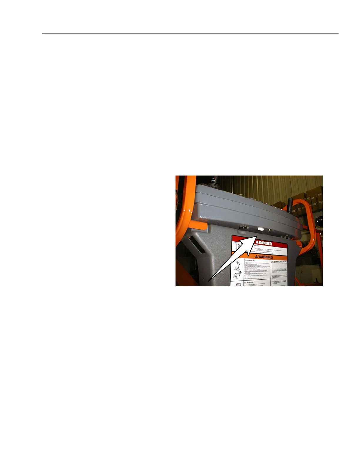
A Machine that incorporates
ADE (JLG Control System) can
be outwardly identified by the
analyzer connection at the base
of the platform control box as
shown by the arrow.
ADE Identification
All 600S, 600SJ, and 660SJ machines from S/N 61927 incorporate ADE (JLG Control System). The following machine serial numbers prior to S/N 61927 also utilize EPBCS: 58993,
58998, 59222, 59223, 59275, 59281, 59315, 59319, 59352, 59358, 59631, 59769, 60253,
60254, 60286, 60642, 60645, 61120, 61257, 61402, 61440, 61491, 61833, 61840, 61875, and
61878.
All 600A and 600AJ machines from S/N 64249 incorporate ADE (JLG Control System). The
following machine serial numbers prior to S/N 64249 also utilize EPBCS: 63908, 63912,
63932, 63936, 63938, 63954, 63959, and 63963.
– JLG Lift –

This page left blank intentionally.
– JLG Lift –
INTRODUCTION
SECTION A. INTRODUCTION - MAINTENANCE SAFETY
PRECAUTIONS
AGENERAL
This section contains the general safety precautions
which must be observed during maintenance of the
aerial platform. It is of utmost importance that maintenance personnel pay strict attention to these warnings and precautions to avoid possible injury to
themselves or others, or damage to the equipment.
A maintenance program must be followed to ensure
that the machine is safe to operate.
MODIFICATION OF THE MACHINE WITHOUT CERTIFICATION BY A
RESPONSIBLE AUTHORITY THAT THE MACHINE IS AT LEAST AS
SAFE AS ORIGINALLY MANUFACTURED, IS A SAFETY VIOLATION.
The specific precautions to be observed during
maintenance are inserted at the appropriate point in
the manual. These precautions are, for the most
part, those that apply when servicing hydraulic and
larger machine component parts.
Your safety, and that of others, is the first consideration when engaging in the maintenance of equipment. Always be conscious of weight. Never attempt
to move heavy parts without the aid of a mechanical
device. Do not allow heavy objects to rest in an
unstable position. When raising a portion of the
equipment, ensure that adequate support is provided.
reservoir. Pressure feed lines to system components
can then be disconnected with minimal fluid loss.
CMAINTENANCE
FAILURE TO COMPLY WITH SAFETY PRECAUTIONS LISTED IN
THIS SECTION MAY RESULT IN MACHINE DAMAGE, PERSONNEL
INJURY OR DEATH AND IS A SAFETY VIOLATION.
• ENSURE REPLACEMENT PARTS OR COMPONENTS
ARE IDENTICAL OR EQUIVALENT TO ORIGINAL PARTS
OR COMPONENTS.
• NO SMOKING IS MANDA T OR Y. NEVER REFUEL DURING ELECTRICAL STORMS. ENSURE THAT FUEL
CAP IS CLOSED AND SECURE AT ALL OTHER
TIMES.
• REMOVE ALL RINGS, WATCHES AND JEWELRY
WHEN PERFORMING ANY MAINTENANCE.
• DO NOT WEAR LONG HAIR UNRESTRAINED, OR
LOOSE-FITTING CLOTHING AND NECKTIES WHICH
ARE APT TO BECOME CAUGHT ON OR ENTANGLED
IN EQUIPMENT.
• OBSERVE AND OBEY ALL WARNINGS AND CAUTIONS ON MACHINE AND IN SERVICEMANUAL.
• KEEP OIL, GREASE, WATER, ETC. WIPED FROM
STANDING SURFACES AND HAND HOLDS.
• USE CAUTION WHEN CHECKING A HOT, PRESSURIZED COOLANT SYSTEM.
• NEVER WORK UNDER AN ELEVATED BOOM UNTIL
SINCE THE MACHINE MANUFACTURER HAS NO DIRECT CONTROL OVER THE FIELD INSPECTION AND MAINTENANCE, SAFETY
IN THIS AREA RESPONSIBILITY OF THE OWNER/OPERATOR.
B HYDRAULIC SYSTEM SAFETY
It should be noted that the machines hydraulic systems operate at extremely high potentially dangerous pressures. Every effort should be made to
relieve any system pressure prior to disconnecting
or removing any portion of the system.
Relieve system pressure by cycling the applicable
control several times with the engine stopped and
BOOM HAS BEEN SAFELY RESTRAINED FROM ANY
MOVEMENT BY BLOCKING OR OVERHEAD SLING,
OR BOOM SAFETY PROP HAS BEEN ENGAGED.
• BEFORE MAKING ADJUSTMENTS, LUBRICATING OR
PERFORMING ANY OTHER MAINTENANCE, SHUT
OFF ALL POWER CONTROLS.
• BATTERY SHOULD ALWAYS BE DISCONNECTEDDURING REPLACEMENT OF ELECTRICAL COMPONENTS.
• KEEP ALL SUPPORT EQUIPMENT AND ATTACHMENTS STOWED IN THEIR PROPER PLACE.
• USE ONL Y APPROVED, NONFLAMMABLE CLEANING
SOLVENTS.
ignition on, to direct any line pressure back into the
3120840 – JLG Lift – A-1

INTRODUCTION
REVISON LOG
Original Issue September, 1996
Revised April 1, 1999
Revised August 4, 2000
Revised November 15, 2000
Revised February 6, 2001
Revised August 29, 2001
Revised June 13, 2002
Revised March 21, 2003
Revised January 28, 2004
Revised September 26, 2005
Revised November 22, 2016
A-2 – JLG Lift – 3120840

TABLE OF CONTENTS
TABLE OF CONTENTS
SUBJECT - SECTION, PARAGRAPH PAGE NO.
SECTION A - INTRODUCTION - MAINTENANCE SAFETY PRECAUTIONS
A General . . . . . . . . . . . . . . . . . . . . . . . . . . . . . . . . . . . . . . . . . . . . . . . . . . . . . . . . . . . . . . . . . . . . . .A-1
B Hydraulic System Safety . . . . . . . . . . . . . . . . . . . . . . . . . . . . . . . . . . . . . . . . . . . . . . . . . . . . . . . . .A-1
C Maintenance . . . . . . . . . . . . . . . . . . . . . . . . . . . . . . . . . . . . . . . . . . . . . . . . . . . . . . . . . . . . . . . . . .A-1
SECTION 1 - SPECIFICATIONS
1.1 Capacities . . . . . . . . . . . . . . . . . . . . . . . . . . . . . . . . . . . . . . . . . . . . . . . . . . . . . . . . . . . . . . . . . . . . 1-1
Fuel Tank . . . . . . . . . . . . . . . . . . . . . . . . . . . . . . . . . . . . . . . . . . . . . . . . . . . . . . . . . . . . . . . . 1-1
Hydraulic Oil Tank . . . . . . . . . . . . . . . . . . . . . . . . . . . . . . . . . . . . . . . . . . . . . . . . . . . . . . . . . 1-1
Hydraulic System (Including Tank) . . . . . . . . . . . . . . . . . . . . . . . . . . . . . . . . . . . . . . . . . . . . 1-1
Torque Hub, Drive . . . . . . . . . . . . . . . . . . . . . . . . . . . . . . . . . . . . . . . . . . . . . . . . . . . . . . . . . 1-1
Engine Crankcase . . . . . . . . . . . . . . . . . . . . . . . . . . . . . . . . . . . . . . . . . . . . . . . . . . . . . . . . . 1-1
1.2 Component Data . . . . . . . . . . . . . . . . . . . . . . . . . . . . . . . . . . . . . . . . . . . . . . . . . . . . . . . . . . . . . . .1-1
Engine - Diesel (Liquid-Cooled) . . . . . . . . . . . . . . . . . . . . . . . . . . . . . . . . . . . . . . . . . . . . . . 1-1
Engine - Diesel (Water-Cooled). . . . . . . . . . . . . . . . . . . . . . . . . . . . . . . . . . . . . . . . . . . . . . . 1-1
Drive System (S Models) . . . . . . . . . . . . . . . . . . . . . . . . . . . . . . . . . . . . . . . . . . . . . . . . . . . . 1-1
Drive System (A Models) . . . . . . . . . . . . . . . . . . . . . . . . . . . . . . . . . . . . . . . . . . . . . . . . . . . . 1-1
Steer System (S Models). . . . . . . . . . . . . . . . . . . . . . . . . . . . . . . . . . . . . . . . . . . . . . . . . . . . 1-2
Steer System (A Models). . . . . . . . . . . . . . . . . . . . . . . . . . . . . . . . . . . . . . . . . . . . . . . . . . . . 1-2
Swing System . . . . . . . . . . . . . . . . . . . . . . . . . . . . . . . . . . . . . . . . . . . . . . . . . . . . . . . . . . . . 1-2
1.3 Performance Data . . . . . . . . . . . . . . . . . . . . . . . . . . . . . . . . . . . . . . . . . . . . . . . . . . . . . . . . . . . . . .1-2
Turning Radius (Outside) (S Models) . . . . . . . . . . . . . . . . . . . . . . . . . . . . . . . . . . . . . . . . . . 1-2
Turning Radius (Outside) (A Models) . . . . . . . . . . . . . . . . . . . . . . . . . . . . . . . . . . . . . . . . . . 1-2
Turning Radius (Inside) (S Models). . . . . . . . . . . . . . . . . . . . . . . . . . . . . . . . . . . . . . . . . . . . 1-2
Turning Radius (Inside) (A Models). . . . . . . . . . . . . . . . . . . . . . . . . . . . . . . . . . . . . . . . . . . . 1-2
Boom Elevation (S Models). . . . . . . . . . . . . . . . . . . . . . . . . . . . . . . . . . . . . . . . . . . . . . . . . . 1-3
Boom Elevation (A Models) . . . . . . . . . . . . . . . . . . . . . . . . . . . . . . . . . . . . . . . . . . . . . . . . . . 1-3
Machine Weight approximately . . . . . . . . . . . . . . . . . . . . . . . . . . . . . . . . . . . . . . . . . . . . . . . 1-3
Machine Height (Stowed) (S Models) . . . . . . . . . . . . . . . . . . . . . . . . . . . . . . . . . . . . . . . . . . 1-3
Machine Height (Stowed) (A Models) . . . . . . . . . . . . . . . . . . . . . . . . . . . . . . . . . . . . . . . . . . 1-3
Machine Length (Stowed) (S Models). . . . . . . . . . . . . . . . . . . . . . . . . . . . . . . . . . . . . . . . . . 1-3
Machine Length (Stowed) (A Models). . . . . . . . . . . . . . . . . . . . . . . . . . . . . . . . . . . . . . . . . . 1-3
Machine Width (S Models) . . . . . . . . . . . . . . . . . . . . . . . . . . . . . . . . . . . . . . . . . . . . . . . . . . 1-3
Machine Width (A Models) . . . . . . . . . . . . . . . . . . . . . . . . . . . . . . . . . . . . . . . . . . . . . . . . . . 1-3
Wheel base (S Models) . . . . . . . . . . . . . . . . . . . . . . . . . . . . . . . . . . . . . . . . . . . . . . . . . . . . . 1-3
Wheel base (A Models) . . . . . . . . . . . . . . . . . . . . . . . . . . . . . . . . . . . . . . . . . . . . . . . . . . . . . 1-3
1.4 Function Speeds . . . . . . . . . . . . . . . . . . . . . . . . . . . . . . . . . . . . . . . . . . . . . . . . . . . . . . . . . . . . . . .1-3
Machine Orientation When Doing Speed Tests . . . . . . . . . . . . . . . . . . . . . . . . . . . . . . . . . . 1-3
Test Notes . . . . . . . . . . . . . . . . . . . . . . . . . . . . . . . . . . . . . . . . . . . . . . . . . . . . . . . . . . . . . . . 1-4
1.5 Torque Requirements . . . . . . . . . . . . . . . . . . . . . . . . . . . . . . . . . . . . . . . . . . . . . . . . . . . . . . . . . . . 1-4
1.6 Lubrication. . . . . . . . . . . . . . . . . . . . . . . . . . . . . . . . . . . . . . . . . . . . . . . . . . . . . . . . . . . . . . . . . . . . 1-5
Deutz F4M1011F Engine . . . . . . . . . . . . . . . . . . . . . . . . . . . . . . . . . . . . . . . . . . . . . . . . . . . . 1-5
Continental TMD27 Engine . . . . . . . . . . . . . . . . . . . . . . . . . . . . . . . . . . . . . . . . . . . . . . . . . . 1-5
Hydraulic Oil . . . . . . . . . . . . . . . . . . . . . . . . . . . . . . . . . . . . . . . . . . . . . . . . . . . . . . . . . . . . . 1-5
Lubrication Specifications . . . . . . . . . . . . . . . . . . . . . . . . . . . . . . . . . . . . . . . . . . . . . . . . . . . 1-6
1.7 Pressure Settings . . . . . . . . . . . . . . . . . . . . . . . . . . . . . . . . . . . . . . . . . . . . . . . . . . . . . . . . . . . . . .1-6
Rexroth Valve (S Models) . . . . . . . . . . . . . . . . . . . . . . . . . . . . . . . . . . . . . . . . . . . . . . . . . . . 1-6
Rexroth Valve (A Models) . . . . . . . . . . . . . . . . . . . . . . . . . . . . . . . . . . . . . . . . . . . . . . . . . . . 1-6
1.8 Cylinder Specifications . . . . . . . . . . . . . . . . . . . . . . . . . . . . . . . . . . . . . . . . . . . . . . . . . . . . . . . . . .1-7
1.9 Major Component Weights . . . . . . . . . . . . . . . . . . . . . . . . . . . . . . . . . . . . . . . . . . . . . . . . . . . . . . .1-8
1.10 Critical Stability Weights . . . . . . . . . . . . . . . . . . . . . . . . . . . . . . . . . . . . . . . . . . . . . . . . . . . . . . . . .1-9
1.11 Serial Number Locations. . . . . . . . . . . . . . . . . . . . . . . . . . . . . . . . . . . . . . . . . . . . . . . . . . . . . . . . .1-14
3120840 – JLG Lift – i

TABLE OF CONTENTS (Continued)
TABLE OF CONTENTS (continued)
SUBJECT - SECTION, PARAGRAPH PAGE NO.
SECTION 2 - GENERAL
2.1 Machine Preparation, Inspection, and Maintenance . . . . . . . . . . . . . . . . . . . . . . . . . . . . . . . . . . .2-1
General . . . . . . . . . . . . . . . . . . . . . . . . . . . . . . . . . . . . . . . . . . . . . . . . . . . . . . . . . . . . . . . . . 2-1
Preparation, Inspection, and Maintenance . . . . . . . . . . . . . . . . . . . . . . . . . . . . . . . . . . . . . . 2-1
Pre-Start Inspection . . . . . . . . . . . . . . . . . . . . . . . . . . . . . . . . . . . . . . . . . . . . . . . . . . . . . . . . 2-1
Pre-Delivery Inspection and Frequent Inspection . . . . . . . . . . . . . . . . . . . . . . . . . . . . . . . . . 2-1
Annual Machine Inspection . . . . . . . . . . . . . . . . . . . . . . . . . . . . . . . . . . . . . . . . . . . . . . . . . . 2-1
Preventative Maintenance . . . . . . . . . . . . . . . . . . . . . . . . . . . . . . . . . . . . . . . . . . . . . . . . . . . 2-1
2.2 Service and Guidelines . . . . . . . . . . . . . . . . . . . . . . . . . . . . . . . . . . . . . . . . . . . . . . . . . . . . . . . . . .2-2
General . . . . . . . . . . . . . . . . . . . . . . . . . . . . . . . . . . . . . . . . . . . . . . . . . . . . . . . . . . . . . . . . . 2-2
Safety and Workmanship . . . . . . . . . . . . . . . . . . . . . . . . . . . . . . . . . . . . . . . . . . . . . . . . . . . 2-2
Cleanliness. . . . . . . . . . . . . . . . . . . . . . . . . . . . . . . . . . . . . . . . . . . . . . . . . . . . . . . . . . . . . . . 2-2
Components Removal and Installation . . . . . . . . . . . . . . . . . . . . . . . . . . . . . . . . . . . . . . . . . 2-2
Component Disassembly and Reassembly . . . . . . . . . . . . . . . . . . . . . . . . . . . . . . . . . . . . . 2-3
Pressure-Fit Parts . . . . . . . . . . . . . . . . . . . . . . . . . . . . . . . . . . . . . . . . . . . . . . . . . . . . . . . . . 2-3
Bearings. . . . . . . . . . . . . . . . . . . . . . . . . . . . . . . . . . . . . . . . . . . . . . . . . . . . . . . . . . . . . . . . . 2-3
Gaskets . . . . . . . . . . . . . . . . . . . . . . . . . . . . . . . . . . . . . . . . . . . . . . . . . . . . . . . . . . . . . . . . . 2-3
Bolt Usage and Torque Application . . . . . . . . . . . . . . . . . . . . . . . . . . . . . . . . . . . . . . . . . . . 2-3
Hydraulic Lines and Electrical Wiring . . . . . . . . . . . . . . . . . . . . . . . . . . . . . . . . . . . . . . . . . . 2-3
Hydraulic System. . . . . . . . . . . . . . . . . . . . . . . . . . . . . . . . . . . . . . . . . . . . . . . . . . . . . . . . . . 2-3
Lubrication . . . . . . . . . . . . . . . . . . . . . . . . . . . . . . . . . . . . . . . . . . . . . . . . . . . . . . . . . . . . . . . 2-3
Battery . . . . . . . . . . . . . . . . . . . . . . . . . . . . . . . . . . . . . . . . . . . . . . . . . . . . . . . . . . . . . . . . . . 2-3
Lubrication and Servicing . . . . . . . . . . . . . . . . . . . . . . . . . . . . . . . . . . . . . . . . . . . . . . . . . . . 2-3
2.3 Lubrication and Information . . . . . . . . . . . . . . . . . . . . . . . . . . . . . . . . . . . . . . . . . . . . . . . . . . . . . .2-4
Hydraulic System. . . . . . . . . . . . . . . . . . . . . . . . . . . . . . . . . . . . . . . . . . . . . . . . . . . . . . . . . . 2-4
Hydraulic Oil . . . . . . . . . . . . . . . . . . . . . . . . . . . . . . . . . . . . . . . . . . . . . . . . . . . . . . . . . . . . . 2-4
Changing Hydraulic Oil . . . . . . . . . . . . . . . . . . . . . . . . . . . . . . . . . . . . . . . . . . . . . . . . . . . . . 2-4
Lubrication Specifications . . . . . . . . . . . . . . . . . . . . . . . . . . . . . . . . . . . . . . . . . . . . . . . . . . . 2-4
2.4 Cylinder Drift Test . . . . . . . . . . . . . . . . . . . . . . . . . . . . . . . . . . . . . . . . . . . . . . . . . . . . . . . . . . . . . . 2-5
Platform Drift . . . . . . . . . . . . . . . . . . . . . . . . . . . . . . . . . . . . . . . . . . . . . . . . . . . . . . . . . . . . . 2-5
Cylinder Drift . . . . . . . . . . . . . . . . . . . . . . . . . . . . . . . . . . . . . . . . . . . . . . . . . . . . . . . . . . . . . 2-5
2.5 Pins and Composite Bearing Repair Guidelines . . . . . . . . . . . . . . . . . . . . . . . . . . . . . . . . . . . . . .2-5
2.6 Welding on JLG Equipment . . . . . . . . . . . . . . . . . . . . . . . . . . . . . . . . . . . . . . . . . . . . . . . . . . . . . .2-6
Do the Following When Welding on JLG Equipment . . . . . . . . . . . . . . . . . . . . . . . . . . . . . . 2-6
Do NOT Do the Following When Welding on JLG Equipment . . . . . . . . . . . . . . . . . . . . . . . 2-6
2.7 Applying Silicone Dielectric Compound to Electrical Connections . . . . . . . . . . . . . . . . . . . . . . . .2-6
2.8 AMP Connector . . . . . . . . . . . . . . . . . . . . . . . . . . . . . . . . . . . . . . . . . . . . . . . . . . . . . . . . . . . . . . . .2-7
Applying Silicone Dielectric Compound to AMP Connectors. . . . . . . . . . . . . . . . . . . . . . . . 2-7
Assembly . . . . . . . . . . . . . . . . . . . . . . . . . . . . . . . . . . . . . . . . . . . . . . . . . . . . . . . . . . . . . . . . 2-7
Disassembly. . . . . . . . . . . . . . . . . . . . . . . . . . . . . . . . . . . . . . . . . . . . . . . . . . . . . . . . . . . . . . 2-9
Wedge Lock. . . . . . . . . . . . . . . . . . . . . . . . . . . . . . . . . . . . . . . . . . . . . . . . . . . . . . . . . . . . . . 2-9
Service - Voltage Reading . . . . . . . . . . . . . . . . . . . . . . . . . . . . . . . . . . . . . . . . . . . . . . . . . . . 2-9
2.9 Deutsch Connectors . . . . . . . . . . . . . . . . . . . . . . . . . . . . . . . . . . . . . . . . . . . . . . . . . . . . . . . . . . . .2-11
DT/DTP Series Assembly. . . . . . . . . . . . . . . . . . . . . . . . . . . . . . . . . . . . . . . . . . . . . . . . . . . . 2-11
DT/DTP Series Disassembly . . . . . . . . . . . . . . . . . . . . . . . . . . . . . . . . . . . . . . . . . . . . . . . . . 2-11
HD30/HDP20 Series Assembly . . . . . . . . . . . . . . . . . . . . . . . . . . . . . . . . . . . . . . . . . . . . . . . 2-12
HD30/HDP20 Series Disassembly. . . . . . . . . . . . . . . . . . . . . . . . . . . . . . . . . . . . . . . . . . . . . 2-12
ii – JLG Lift – 3120840

TABLE OF CONTENTS
TABLE OF CONTENTS (continued)
SUBJECT - SECTION, PARAGRAPH PAGE NO.
SECTION 3 - CHASSIS & TURNTABLE
3.1 Drive Torque hub, Prior to S/N 75606 . . . . . . . . . . . . . . . . . . . . . . . . . . . . . . . . . . . . . . . . . . . . . .3-1
Disassembly. . . . . . . . . . . . . . . . . . . . . . . . . . . . . . . . . . . . . . . . . . . . . . . . . . . . . . . . . . . . . . 3-1
Cleaning and Inspection . . . . . . . . . . . . . . . . . . . . . . . . . . . . . . . . . . . . . . . . . . . . . . . . . . . . 3-1
Repair. . . . . . . . . . . . . . . . . . . . . . . . . . . . . . . . . . . . . . . . . . . . . . . . . . . . . . . . . . . . . . . . . . . 3-3
Assembly . . . . . . . . . . . . . . . . . . . . . . . . . . . . . . . . . . . . . . . . . . . . . . . . . . . . . . . . . . . . . . . . 3-5
3.2 Torque Hub, Drive (Auburn Gear). . . . . . . . . . . . . . . . . . . . . . . . . . . . . . . . . . . . . . . . . . . . . . . . . .3-9
Disassembly. . . . . . . . . . . . . . . . . . . . . . . . . . . . . . . . . . . . . . . . . . . . . . . . . . . . . . . . . . . . . . 3-9
Assembly . . . . . . . . . . . . . . . . . . . . . . . . . . . . . . . . . . . . . . . . . . . . . . . . . . . . . . . . . . . . . . . . 3-9
3.3 Drive Torque hub, S/N 75606 to Present . . . . . . . . . . . . . . . . . . . . . . . . . . . . . . . . . . . . . . . . . . . .3-12
Roll, Leak and Brake Testing. . . . . . . . . . . . . . . . . . . . . . . . . . . . . . . . . . . . . . . . . . . . . . . . . 3-12
Tightening and Torquing Bolts . . . . . . . . . . . . . . . . . . . . . . . . . . . . . . . . . . . . . . . . . . . . . . . 3-12
Main Disassembly . . . . . . . . . . . . . . . . . . . . . . . . . . . . . . . . . . . . . . . . . . . . . . . . . . . . . . . . . 3-13
Input Carrier Disassembly . . . . . . . . . . . . . . . . . . . . . . . . . . . . . . . . . . . . . . . . . . . . . . . . . . . 3-16
Hub-Spindle Disassembly . . . . . . . . . . . . . . . . . . . . . . . . . . . . . . . . . . . . . . . . . . . . . . . . . . . 3-17
Spindle-Brake Disassembly. . . . . . . . . . . . . . . . . . . . . . . . . . . . . . . . . . . . . . . . . . . . . . . . . . 3-18
Cover Disassembly . . . . . . . . . . . . . . . . . . . . . . . . . . . . . . . . . . . . . . . . . . . . . . . . . . . . . . . . 3-20
Input Carrier Sub-Assembly . . . . . . . . . . . . . . . . . . . . . . . . . . . . . . . . . . . . . . . . . . . . . . . . . 3-21
Output Planet Gear Sub-Assembly . . . . . . . . . . . . . . . . . . . . . . . . . . . . . . . . . . . . . . . . . . . . 3-21
Spindle - Brake Sub-Assembly . . . . . . . . . . . . . . . . . . . . . . . . . . . . . . . . . . . . . . . . . . . . . . . 3-21
Hub-Spindle Sub-Assembly . . . . . . . . . . . . . . . . . . . . . . . . . . . . . . . . . . . . . . . . . . . . . . . . . 3-22
Cover Sub-Assembly . . . . . . . . . . . . . . . . . . . . . . . . . . . . . . . . . . . . . . . . . . . . . . . . . . . . . . . 3-23
Main Assembly. . . . . . . . . . . . . . . . . . . . . . . . . . . . . . . . . . . . . . . . . . . . . . . . . . . . . . . . . . . . 3-23
Integral Brake Check . . . . . . . . . . . . . . . . . . . . . . . . . . . . . . . . . . . . . . . . . . . . . . . . . . . . . . . 3-23
3.4 Drive Brake - Mico . . . . . . . . . . . . . . . . . . . . . . . . . . . . . . . . . . . . . . . . . . . . . . . . . . . . . . . . . . . . . .3-27
Disassembly. . . . . . . . . . . . . . . . . . . . . . . . . . . . . . . . . . . . . . . . . . . . . . . . . . . . . . . . . . . . . . 3-27
Inspection . . . . . . . . . . . . . . . . . . . . . . . . . . . . . . . . . . . . . . . . . . . . . . . . . . . . . . . . . . . . . . . 3-27
Assembly . . . . . . . . . . . . . . . . . . . . . . . . . . . . . . . . . . . . . . . . . . . . . . . . . . . . . . . . . . . . . . . . 3-27
3.5 Free Wheeling Option . . . . . . . . . . . . . . . . . . . . . . . . . . . . . . . . . . . . . . . . . . . . . . . . . . . . . . . . . . .3-29
To Disengage Drive Motors and Brakes (Free Wheel) for Towing, etc. . . . . . . . . . . . . . . . . 3-29
To Engage Drive Motors and Brakes (Normal Operation) . . . . . . . . . . . . . . . . . . . . . . . . . . 3-29
3.6 Drive Motor (600S, 600A 4WD) . . . . . . . . . . . . . . . . . . . . . . . . . . . . . . . . . . . . . . . . . . . . . . . . . . . .3-30
Spare Parts Kits . . . . . . . . . . . . . . . . . . . . . . . . . . . . . . . . . . . . . . . . . . . . . . . . . . . . . . . . . . . 3-30
Replacing the Drive Shaft Seal . . . . . . . . . . . . . . . . . . . . . . . . . . . . . . . . . . . . . . . . . . . . . . . 3-31
Disassembly and Assembly . . . . . . . . . . . . . . . . . . . . . . . . . . . . . . . . . . . . . . . . . . . . . . . . . 3-32
Assembly Notes. . . . . . . . . . . . . . . . . . . . . . . . . . . . . . . . . . . . . . . . . . . . . . . . . . . . . . . . . . . 3-36
Taper Roller Bearing Initial Tension . . . . . . . . . . . . . . . . . . . . . . . . . . . . . . . . . . . . . . . . . . . 3-36
Testing and Setup . . . . . . . . . . . . . . . . . . . . . . . . . . . . . . . . . . . . . . . . . . . . . . . . . . . . . . . . . 3-38
3.7 Drive Motor Adjustment Procedure (S Models Only) . . . . . . . . . . . . . . . . . . . . . . . . . . . . . . . . . . .3-38
3.8 Oscillating Axle Bleeding Procedure and Lockout Test . . . . . . . . . . . . . . . . . . . . . . . . . . . . . . . . .3-39
Lockout Cylinder Bleeding . . . . . . . . . . . . . . . . . . . . . . . . . . . . . . . . . . . . . . . . . . . . . . . . . . 3-39
Oscillating Axle Lockout Test . . . . . . . . . . . . . . . . . . . . . . . . . . . . . . . . . . . . . . . . . . . . . . . . 3-40
3.9 Steer Adjustments (S Models) . . . . . . . . . . . . . . . . . . . . . . . . . . . . . . . . . . . . . . . . . . . . . . . . . . . .3-41
3.10 Swing Hub . . . . . . . . . . . . . . . . . . . . . . . . . . . . . . . . . . . . . . . . . . . . . . . . . . . . . . . . . . . . . . . . . . . .3-41
Adjustment Procedures . . . . . . . . . . . . . . . . . . . . . . . . . . . . . . . . . . . . . . . . . . . . . . . . . . . . . 3-41
3.11 Swing Bearing . . . . . . . . . . . . . . . . . . . . . . . . . . . . . . . . . . . . . . . . . . . . . . . . . . . . . . . . . . . . . . . . .3-42
Turntable Bearing Mounting Bolt Condition Check . . . . . . . . . . . . . . . . . . . . . . . . . . . . . . . 3-42
Wear Tolerance.(S & A Models) . . . . . . . . . . . . . . . . . . . . . . . . . . . . . . . . . . . . . . . . . . . . . . 3-43
Swing Bearing Replacement . . . . . . . . . . . . . . . . . . . . . . . . . . . . . . . . . . . . . . . . . . . . . . . . . 3-46
Swing Bearing Torque Values . . . . . . . . . . . . . . . . . . . . . . . . . . . . . . . . . . . . . . . . . . . . . . . . 3-47
3120840 – JLG Lift – iii

TABLE OF CONTENTS (Continued)
TABLE OF CONTENTS (continued)
SUBJECT - SECTION, PARAGRAPH PAGE NO.
3.12 Swing Brake - Mico . . . . . . . . . . . . . . . . . . . . . . . . . . . . . . . . . . . . . . . . . . . . . . . . . . . . . . . . . . . . .3-47
Disassembly. . . . . . . . . . . . . . . . . . . . . . . . . . . . . . . . . . . . . . . . . . . . . . . . . . . . . . . . . . . . . . 3-47
Inspection . . . . . . . . . . . . . . . . . . . . . . . . . . . . . . . . . . . . . . . . . . . . . . . . . . . . . . . . . . . . . . . 3-49
Assembly . . . . . . . . . . . . . . . . . . . . . . . . . . . . . . . . . . . . . . . . . . . . . . . . . . . . . . . . . . . . . . . . 3-49
3.13 Tilt Alarm Switch (Machines w/ External Tilt . . . . . . . . . . . . . . . . . . . . . . . . . . . . . . . . . . . . . . . . . .3-49
Manual Adjustment . . . . . . . . . . . . . . . . . . . . . . . . . . . . . . . . . . . . . . . . . . . . . . . . . . . . . . . . 3-49
3.14 Spark Arrester Cleaning Instructions . . . . . . . . . . . . . . . . . . . . . . . . . . . . . . . . . . . . . . . . . . . . . . .3-50
3.15 Throttle Checks and Adjustments - Deutz Engine . . . . . . . . . . . . . . . . . . . . . . . . . . . . . . . . . . . . .3-50
General . . . . . . . . . . . . . . . . . . . . . . . . . . . . . . . . . . . . . . . . . . . . . . . . . . . . . . . . . . . . . . . . . 3-50
Procedure . . . . . . . . . . . . . . . . . . . . . . . . . . . . . . . . . . . . . . . . . . . . . . . . . . . . . . . . . . . . . . . 3-50
3.16 Throttle Checks and Adjustments - TMD 27 Continental Engine. . . . . . . . . . . . . . . . . . . . . . . . . . 3-50
SECTION 4 - BOOM & PLATFORM
4.1 Boom Rope Torquing Procedures . . . . . . . . . . . . . . . . . . . . . . . . . . . . . . . . . . . . . . . . . . . . . . . . . 4-1
Torque Procedures (S Models) . . . . . . . . . . . . . . . . . . . . . . . . . . . . . . . . . . . . . . . . . . . . . . . 4-1
4.2 Wear Pads . . . . . . . . . . . . . . . . . . . . . . . . . . . . . . . . . . . . . . . . . . . . . . . . . . . . . . . . . . . . . . . . . . . .4-1
Tower Boom (A Models) . . . . . . . . . . . . . . . . . . . . . . . . . . . . . . . . . . . . . . . . . . . . . . . . . . . . 4-1
Main Boom. . . . . . . . . . . . . . . . . . . . . . . . . . . . . . . . . . . . . . . . . . . . . . . . . . . . . . . . . . . . . . . 4-1
4.3 Wire Rope (S Models) . . . . . . . . . . . . . . . . . . . . . . . . . . . . . . . . . . . . . . . . . . . . . . . . . . . . . . . . . . .4-2
Inspection . . . . . . . . . . . . . . . . . . . . . . . . . . . . . . . . . . . . . . . . . . . . . . . . . . . . . . . . . . . . . . . 4-2
Three Month Inspection. . . . . . . . . . . . . . . . . . . . . . . . . . . . . . . . . . . . . . . . . . . . . . . . . . . . . 4-3
12 Year or 7000 Hour Replacement. . . . . . . . . . . . .
Additional Replacement Criteria . . . . . . . . . . . . . . . . . . . . . . . . . . . . . . . . . . . . . . . . . . . . . . 4-3
4.4 Boom Maintenance (S Models) . . . . . . . . . . . . . . . . . . . . . . . . . . . . . . . . . . . . . . . . . . . . . . . . . . .4-3
Removal . . . . . . . . . . . . . . . . . . . . . . . . . . . . . . . . . . . . . . . . . . . . . . . . . . . . . . . . . . . . . . . . . 4-3
Disassembly of Boom Sections. . . . . . . . . . . . . . . . . . . . . . . . . . . . . . . . . . . . . . . . . . . . . . . 4-8
Inspection . . . . . . . . . . . . . . . . . . . . . . . . . . . . . . . . . . . . . . . . . . . . . . . . . . . . . . . . . . . . . . . 4-9
Assembly . . . . . . . . . . . . . . . . . . . . . . . . . . . . . . . . . . . . . . . . . . . . . . . . . . . . . . . . . . . . . . . . 4-10
Installation . . . . . . . . . . . . . . . . . . . . . . . . . . . . . . . . . . . . . . . . . . . . . . . . . . . . . . . . . . . . . . . 4-12
4.5 Boom Maintenance (A Models) . . . . . . . . . . . . . . . . . . . . . . . . . . . . . . . . . . . . . . . . . . . . . . . . . . .4-12
Removal . . . . . . . . . . . . . . . . . . . . . . . . . . . . . . . . . . . . . . . . . . . . . . . . . . . . . . . . . . . . . . . . . 4-12
Disassembly of Boom Sections. . . . . . . . . . . . . . . . . . . . . . . . . . . . . . . . . . . . . . . . . . . . . . . 4-15
Inspection . . . . . . . . . . . . . . . . . . . . . . . . . . . . . . . . . . . . . . . . . . . . . . . . . . . . . . . . . . . . . . . 4-15
Assembly . . . . . . . . . . . . . . . . . . . . . . . . . . . . . . . . . . . . . . . . . . . . . . . . . . . . . . . . . . . . . . . . 4-15
Installation . . . . . . . . . . . . . . . . . . . . . . . . . . . . . . . . . . . . . . . . . . . . . . . . . . . . . . . . . . . . . . . 4-16
4.6 Tower Boom . . . . . . . . . . . . . . . . . . . . . . . . . . . . . . . . . . . . . . . . . . . . . . . . . . . . . . . . . . . . . . . . . .4-16
Removal . . . . . . . . . . . . . . . . . . . . . . . . . . . . . . . . . . . . . . . . . . . . . . . . . . . . . . . . . . . . . . . . . 4-16
Disassembly. . . . . . . . . . . . . . . . . . . . . . . . . . . . . . . . . . . . . . . . . . . . . . . . . . . . . . . . . . . . . . 4-17
Inspection . . . . . . . . . . . . . . . . . . . . . . . . . . . . . . . . . . . . . . . . . . . . . . . . . . . . . . . . . . . . . . . 4-18
Assembly . . . . . . . . . . . . . . . . . . . . . . . . . . . . . . . . . . . . . . . . . . . . . . . . . . . . . . . . . . . . . . . . 4-18
Installation . . . . . . . . . . . . . . . . . . . . . . . . . . . . . . . . . . . . . . . . . . . . . . . . . . . . . . . . . . . . . . . 4-18
4.7 Articulating Jib Boom . . . . . . . . . . . . . . . . . . . . . . . . . . . . . . . . . . . . . . . . . . . . . . . . . . . . . . . . . . .4-19
Removal . . . . . . . . . . . . . . . . . . . . . . . . . . . . . . . . . . . . . . . . . . . . . . . . . . . . . . . . . . . . . . . . . 4-19
Disassembly. . . . . . . . . . . . . . . . . . . . . . . . . . . . . . . . . . . . . . . . . . . . . . . . . . . . . . . . . . . . . . 4-19
Inspection . . . . . . . . . . . . . . . . . . . . . . . . . . . . . . . . . . . . . . . . . . . . . . . . . . . . . . . . . . . . . . . 4-19
Assembly . . . . . . . . . . . . . . . . . . . . . . . . . . . . . . . . . . . . . . . . . . . . . . . . . . . . . . . . . . . . . . . . 4-20
Main Boom Telescope Cylinder Removal . . . . . . . . . . . . . . . . . . . . . . . . . . . . . . . . . . . . . . . 4-20
Main Boom Telescope Cylinder Installation . . . . . . . . . . . . . . . . . . . . . . . . . . . . . . . . . . . . . 4-21
Main Boom Lift Cylinder Removal . . . . . . . . . . . . . . . . . . . . . . . . . . . . . . . . . . . . . . . . . . . . . 4-22
Main Boom Lift Cylinder Installation . . . . . . . . . . . . . . . . . . . . . . . . . . . . . . . . . . . . . . . . . . . 4-22
. . . . . . . . . . . . . . . . . . . . . . . . . . . . . . . 4-3
iv – JLG Lift – 3120840

TABLE OF CONTENTS
TABLE OF CONTENTS (continued)
SUBJECT - SECTION, PARAGRAPH PAGE NO.
4.8 Limit Switches and Cam Valve Adjustment . . . . . . . . . . . . . . . . . . . . . . . . . . . . . . . . . . . . . . . . . .4-22
4.9 Platform . . . . . . . . . . . . . . . . . . . . . . . . . . . . . . . . . . . . . . . . . . . . . . . . . . . . . . . . . . . . . . . . . . . . . .4-25
Platform Sections Replacement . . . . . . . . . . . . . . . . . . . . . . . . . . . . . . . . . . . . . . . . . . . . . . 4-25
4.10 Rotator - Helac. . . . . . . . . . . . . . . . . . . . . . . . . . . . . . . . . . . . . . . . . . . . . . . . . . . . . . . . . . . . . . . . .4-25
Disassembly. . . . . . . . . . . . . . . . . . . . . . . . . . . . . . . . . . . . . . . . . . . . . . . . . . . . . . . . . . . . . . 4-25
Inspection . . . . . . . . . . . . . . . . . . . . . . . . . . . . . . . . . . . . . . . . . . . . . . . . . . . . . . . . . . . . . . . 4-27
Assembly . . . . . . . . . . . . . . . . . . . . . . . . . . . . . . . . . . . . . . . . . . . . . . . . . . . . . . . . . . . . . . . . 4-27
4.11 Drive Card Setup Procedures . . . . . . . . . . . . . . . . . . . . . . . . . . . . . . . . . . . . . . . . . . . . . . . . . . . . .4-28
Lift, Swing, and Drive Cards . . . . . . . . . . . . . . . . . . . . . . . . . . . . . . . . . . . . . . . . . . . . . . . . . 4-29
Flow Control Card . . . . . . . . . . . . . . . . . . . . . . . . . . . . . . . . . . . . . . . . . . . . . . . . . . . . . . . . . 4-29
4.12 Foot Switch Adjustment . . . . . . . . . . . . . . . . . . . . . . . . . . . . . . . . . . . . . . . . . . . . . . . . . . . . . . . . .4-30
4.13 Boom Synchronizing Procedure (A Models Only) . . . . . . . . . . . . . . . . . . . . . . . . . . . . . . . . . . . . . 4-30
SECTION 5 - HYDRAULICS
5.1 Cylinders - Theory of Operation . . . . . . . . . . . . . . . . . . . . . . . . . . . . . . . . . . . . . . . . . . . . . . . . . . .5-1
Systems Incorporating Double Acting Cylinders . . . . . . . . . . . . . . . . . . . . . . . . . . . . . . . . . 5-1
Systems Incorporating Holding Valves . . . . . . . . . . . . . . . . . . . . . . . . . . . . . . . . . . . . . . . . . 5-1
5.2 Cylinder Checking Procedure. . . . . . . . . . . . . . . . . . . . . . . . . . . . . . . . . . . . . . . . . . . . . . . . . . . . . 5-1
Cylinders Without Counterbalance Valves - Master Cylinder and Steer Cylinder . . . . . . . . 5-1
Cylinders With Single Counterbalance Valve . . . . . . . . . . . . . . . . . . . . . . . . . . . . . . . . . . . . 5-1
Cylinders With Dual Counterbalance Valves. . . . . . . . . . . . . . . . . . . . . . . . . . . . . . . . . . . . . 5-2
5.3 Cylinder Repair . . . . . . . . . . . . . . . . . . . . . . . . . . . . . . . . . . . . . . . . . . . . . . . . . . . . . . . . . . . . . . . .5-2
Disassembly. . . . . . . . . . . . . . . . . . . . . . . . . . . . . . . . . . . . . . . . . . . . . . . . . . . . . . . . . . . . . . 5-2
Cleaning and Inspection . . . . . . . . . . . . . . . . . . . . . . . . . . . . . . . . . . . . . . . . . . . . . . . . . . . . 5-4
Assembly . . . . . . . . . . . . . . . . . . . . . . . . . . . . . . . . . . . . . . . . . . . . . . . . . . . . . . . . . . . . . . . . 5-5
5.4 Cylinder Removal and Installation (S Models) . . . . . . . . . . . . . . . . . . . . . . . . . . . . . . . . . . . . . . . .5-9
Main Boom Telescope Cylinder Removal . . . . . . . . . . . . . . . . . . . . . . . . . . . . . . . . . . . . . . . 5-9
Main Boom Telescope Cylinder Installation . . . . . . . . . . . . . . . . . . . . . . . . . . . . . . . . . . . . . 5-9
Main Boom Lift Cylinder Removal . . . . . . . . . . . . . . . . . . . . . . . . . . . . . . . . . . . . . . . . . . . . . 5-10
Main Boom Lift Cylinder Installation . . . . . . . . . . . . . . . . . . . . . . . . . . . . . . . . . . . . . . . . . . . 5-11
5.5 Cylinder Removal and Installation (A Models) . . . . . . . . . . . . . . . . . . . . . . . . . . . . . . . . . . . . . . . .5-11
Main Boom Telescope Cylinder Removal . . . . . . . . . . . . . . . . . . . . . . . . . . . . . . . . . . . . . . . 5-11
Main Boom Telescope Cylinder Installation . . . . . . . . . . . . . . . . . . . . . . . . . . . . . . . . . . . . . 5-12
Main Boom Lift Cylinder Removal . . . . . . . . . . . . . . . . . . . . . . . . . . . . . . . . . . . . . . . . . . . . . 5-12
Main Boom Lift Cylinder Installation . . . . . . . . . . . . . . . . . . . . . . . . . . . . . . . . . . . . . . . . . . . 5-13
Upright Level Cylinder Removal . . . . . . . . . . . . . . . . . . . . . . . . . . . . . . . . . . . . . . . . . . . . . . 5-13
Upright Level Cylinder Installation. . . . . . . . . . . . . . . . . . . . . . . . . . . . . . . . . . . . . . . . . . . . . 5-14
Tower Boom Lift Cylinder Removal . . . . . . . . . . . . . . . . . . . . . . . . . . . . . . . . . . . . . . . . . . . . 5-14
Tower Lift Cylinder Installation. . . . . . . . . . . . . . . . . . . . . . . . . . . . . . . . . . . . . . . . . . . . . . . . 5-14
Tower Telescope Cylinder Removal . . . . . . . . . . . . . . . . . . . . . . . . . . . . . . . . . . . . . . . . . . . 5-15
Tower Telescope Cylinder Installation . . . . . . . . . . . . . . . . . . . . . . . . . . . . . . . . . . . . . . . . . 5-17
3120840 – JLG Lift – v

TABLE OF CONTENTS (Continued)
TABLE OF CONTENTS (continued)
SUBJECT - SECTION, PARAGRAPH PAGE NO.
5.6 Variable Displacement pump (M46 series). . . . . . . . . . . . . . . . . . . . . . . . . . . . . . . . . . . . . . . . . . .5-32
Troubleshooting. . . . . . . . . . . . . . . . . . . . . . . . . . . . . . . . . . . . . . . . . . . . . . . . . . . . . . . . . . . 5-32
Inspections and Adjustments . . . . . . . . . . . . . . . . . . . . . . . . . . . . . . . . . . . . . . . . . . . . . . . . 5-35
Minor Repair and Replacement. . . . . . . . . . . . . . . . . . . . . . . . . . . . . . . . . . . . . . . . . . . . . . . 5-38
5.7 Valves - Theory of Operation. . . . . . . . . . . . . . . . . . . . . . . . . . . . . . . . . . . . . . . . . . . . . . . . . . . . . . 5-43
Solenoid Control Valve - Rexroth . . . . . . . . . . . . . . . . . . . . . . . . . . . . . . . . . . . . . . . . . . . . . 5-43
Relief Valves. . . . . . . . . . . . . . . . . . . . . . . . . . . . . . . . . . . . . . . . . . . . . . . . . . . . . . . . . . . . . . 5-43
5.8 Pressure Setting Procedures (S and A Models) . . . . . . . . . . . . . . . . . . . . . . . . . . . . . . . . . . . . . . . 5-43
Main Relief, Steer, Swing and Lift Down . . . . . . . . . . . . . . . . . . . . . . . . . . . . . . . . . . . . . . . . 5-43
Platform Level . . . . . . . . . . . . . . . . . . . . . . . . . . . . . . . . . . . . . . . . . . . . . . . . . . . . . . . . . . . . 5-44
Articulating Jib Boom (If Equipped) . . . . . . . . . . . . . . . . . . . . . . . . . . . . . . . . . . . . . . . . . . . 5-44
4 Wheel Steer (If Equipped) . . . . . . . . . . . . . . . . . . . . . . . . . . . . . . . . . . . . . . . . . . . . . . . . . 5-44
5.9 Hydraulic Component Start-Up Procedures and Recommendations . . . . . . . . . . . . . . . . . . . . . . 5-48
5.10 Hydraulic Pump W/hayes Pump Drive Coupling Lubrication. . . . . . . . . . . . . . . . . . . . . . . . . . . . .5-49
SECTION 6 - JLG CONTROL SYSTEM
6.1 Introduction . . . . . . . . . . . . . . . . . . . . . . . . . . . . . . . . . . . . . . . . . . . . . . . . . . . . . . . . . . . . . . . . . . .6-1
6.2 To Connect the JLG Control System Analyzer . . . . . . . . . . . . . . . . . . . . . . . . . . . . . . . . . . . . . . . .6-3
6.3 Using the Analyzer . . . . . . . . . . . . . . . . . . . . . . . . . . . . . . . . . . . . . . . . . . . . . . . . . . . . . . . . . . . . .6-3
6.4 Changing the Access Level of the Hand Held Analyzer. . . . . . . . . . . . . . . . . . . . . . . . . . . . . . . . . 6-5
6.5 Adjusting Parameters Using the Hand Held Analyzer . . . . . . . . . . . . . . . . . . . . . . . . . . . . . . . . . .6-7
6.6 Machine Setup . . . . . . . . . . . . . . . . . . . . . . . . . . . . . . . . . . . . . . . . . . . . . . . . . . . . . . . . . . . . . . . .6-8
6.7 Level Vehicle Description . . . . . . . . . . . . . . . . . . . . . . . . . . . . . . . . . . . . . . . . . . . . . . . . . . . . . . . .6-8
6.8 Machine Personality Settings . . . . . . . . . . . . . . . . . . . . . . . . . . . . . . . . . . . . . . . . . . . . . . . . . . . . .6-13
6.9 Analyzer Diagnostics Menu Structure. . . . . . . . . . . . . . . . . . . . . . . . . . . . . . . . . . . . . . . . . . . . . . .6-38
SECTION 7 - SCHEMATICS
7.1 General . . . . . . . . . . . . . . . . . . . . . . . . . . . . . . . . . . . . . . . . . . . . . . . . . . . . . . . . . . . . . . . . . . . . . .7-1
7.2 Troubleshooting . . . . . . . . . . . . . . . . . . . . . . . . . . . . . . . . . . . . . . . . . . . . . . . . . . . . . . . . . . . . . . .7-1
7.3 Hydraulic Circuit Checks. . . . . . . . . . . . . . . . . . . . . . . . . . . . . . . . . . . . . . . . . . . . . . . . . . . . . . . . .7-1
vi – JLG Lift – 3120840

TABLE OF CONTENTS
LIST OF FIGURES
FIGURE NO. TITLE PAGE NO.
1-1. 600S Lug Torques . . . . . . . . . . . . . . . . . . . . . . . . . . . . . . . . . . . . . . . . . . . . . . . . . . . . . . . . . . . . . .1-4
1-2. Lubrication Point Location - S Models . . . . . . . . . . . . . . . . . . . . . . . . . . . . . . . . . . . . . . . . . . . . . .1-10
1-3. Lubrication Point Location - A Models . . . . . . . . . . . . . . . . . . . . . . . . . . . . . . . . . . . . . . . . . . . . . .1-12
1-4. Serial Number Locations. . . . . . . . . . . . . . . . . . . . . . . . . . . . . . . . . . . . . . . . . . . . . . . . . . . . . . . . .1-14
1-5. Torque Chart . . . . . . . . . . . . . . . . . . . . . . . . . . . . . . . . . . . . . . . . . . . . . . . . . . . . . . . . . . . . . . . . . .1-15
2-1. Connector Assembly Figure 1. . . . . . . . . . . . . . . . . . . . . . . . . . . . . . . . . . . . . . . . . . . . . . . . . . . . .2-7
2-2. AMP Connector . . . . . . . . . . . . . . . . . . . . . . . . . . . . . . . . . . . . . . . . . . . . . . . . . . . . . . . . . . . . . . . .2-7
2-3. Connector Assembly Figure 2. . . . . . . . . . . . . . . . . . . . . . . . . . . . . . . . . . . . . . . . . . . . . . . . . . . . .2-8
2-4. Connector Assembly Figure 3. . . . . . . . . . . . . . . . . . . . . . . . . . . . . . . . . . . . . . . . . . . . . . . . . . . . .2-8
2-5. Connector Assembly Figure 4. . . . . . . . . . . . . . . . . . . . . . . . . . . . . . . . . . . . . . . . . . . . . . . . . . . . .2-8
2-6. Connector Disassembly . . . . . . . . . . . . . . . . . . . . . . . . . . . . . . . . . . . . . . . . . . . . . . . . . . . . . . . . .2-9
2-7. Connector Installation . . . . . . . . . . . . . . . . . . . . . . . . . . . . . . . . . . . . . . . . . . . . . . . . . . . . . . . . . . .2-10
2-8. DT/DTP Contact Installation . . . . . . . . . . . . . . . . . . . . . . . . . . . . . . . . . . . . . . . . . . . . . . . . . . . . . .2-11
2-9. DT/DTP Contact Removal . . . . . . . . . . . . . . . . . . . . . . . . . . . . . . . . . . . . . . . . . . . . . . . . . . . . . . . .2-11
2-10. HD/HDP Contact Installation . . . . . . . . . . . . . . . . . . . . . . . . . . . . . . . . . . . . . . . . . . . . . . . . . . . . . . 2-12
2-11. HD/HDP Locking Contacts Into Position . . . . . . . . . . . . . . . . . . . . . . . . . . . . . . . . . . . . . . . . . . . .2-12
2-12. HD/HDP Contact Removal . . . . . . . . . . . . . . . . . . . . . . . . . . . . . . . . . . . . . . . . . . . . . . . . . . . . . . .2-12
2-13. HD/HDP Unlocking Contacts . . . . . . . . . . . . . . . . . . . . . . . . . . . . . . . . . . . . . . . . . . . . . . . . . . . . .2-12
2-14. Engine Operating Temperature Specifications - Deutz . . . . . . . . . . . . . . . . . . . . . . . . . . . . . . . . .2-16
3-1. Torque Hub, Drive (Fairfield). . . . . . . . . . . . . . . . . . . . . . . . . . . . . . . . . . . . . . . . . . . . . . . . . . . . . .3-2
3-2. Torque Hub, Drive (Auburn Gear). . . . . . . . . . . . . . . . . . . . . . . . . . . . . . . . . . . . . . . . . . . . . . . . . .3-10
3-3. Main Disassembly . . . . . . . . . . . . . . . . . . . . . . . . . . . . . . . . . . . . . . . . . . . . . . . . . . . . . . . . . . . . . .3-13
3-4. Input Carrier. . . . . . . . . . . . . . . . . . . . . . . . . . . . . . . . . . . . . . . . . . . . . . . . . . . . . . . . . . . . . . . . . . .3-14
3-5. Planet Gear Sub Assembly . . . . . . . . . . . . . . . . . . . . . . . . . . . . . . . . . . . . . . . . . . . . . . . . . . . . . . .3-15
3-6. Input Carrier. . . . . . . . . . . . . . . . . . . . . . . . . . . . . . . . . . . . . . . . . . . . . . . . . . . . . . . . . . . . . . . . . . .3-16
3-7. Planet Gear Subassembly. . . . . . . . . . . . . . . . . . . . . . . . . . . . . . . . . . . . . . . . . . . . . . . . . . . . . . . . 3-16
3-8. Hub Spindle. . . . . . . . . . . . . . . . . . . . . . . . . . . . . . . . . . . . . . . . . . . . . . . . . . . . . . . . . . . . . . . . . . .3-17
3-9. Spindle Brake . . . . . . . . . . . . . . . . . . . . . . . . . . . . . . . . . . . . . . . . . . . . . . . . . . . . . . . . . . . . . . . . .3-18
3-10. Coupling Subassembly . . . . . . . . . . . . . . . . . . . . . . . . . . . . . . . . . . . . . . . . . . . . . . . . . . . . . . . . . .3-18
3-11. Cover . . . . . . . . . . . . . . . . . . . . . . . . . . . . . . . . . . . . . . . . . . . . . . . . . . . . . . . . . . . . . . . . . . . . . . . .3-20
3-12. Hub Assembly . . . . . . . . . . . . . . . . . . . . . . . . . . . . . . . . . . . . . . . . . . . . . . . . . . . . . . . . . . . . . . . . .3-24
3-13. Bearing Cup Pressing Tool . . . . . . . . . . . . . . . . . . . . . . . . . . . . . . . . . . . . . . . . . . . . . . . . . . . . . . .3-25
3-14. Seal Pressing Tool . . . . . . . . . . . . . . . . . . . . . . . . . . . . . . . . . . . . . . . . . . . . . . . . . . . . . . . . . . . . .3-25
3-15. Bearing Cup Pressing Tool . . . . . . . . . . . . . . . . . . . . . . . . . . . . . . . . . . . . . . . . . . . . . . . . . . . . . . .3-26
3-16. Drift Pin for Lining Up Thrust Washers with Output Planet Gear . . . . . . . . . . . . . . . . . . . . . . . . . .3-26
3-17. Drive Brake Assembly (Mico) . . . . . . . . . . . . . . . . . . . . . . . . . . . . . . . . . . . . . . . . . . . . . . . . . . . . . 3-28
3-18. Disconnecting the Drive Hubs . . . . . . . . . . . . . . . . . . . . . . . . . . . . . . . . . . . . . . . . . . . . . . . . . . . .3-29
3-19. Flow Control Pilot Valves. . . . . . . . . . . . . . . . . . . . . . . . . . . . . . . . . . . . . . . . . . . . . . . . . . . . . . . . . 3-37
3-20. Drive Motor Adjustment (S Models) . . . . . . . . . . . . . . . . . . . . . . . . . . . . . . . . . . . . . . . . . . . . . . . . 3-38
3-21. Oscillating Valve Adjustment. . . . . . . . . . . . . . . . . . . . . . . . . . . . . . . . . . . . . . . . . . . . . . . . . . . . . .3-39
3-22. Brake Valve Wiring Connection. . . . . . . . . . . . . . . . . . . . . . . . . . . . . . . . . . . . . . . . . . . . . . . . . . . .3-39
3-23. Drive Manual Control Valve. . . . . . . . . . . . . . . . . . . . . . . . . . . . . . . . . . . . . . . . . . . . . . . . . . . . . . .3-39
3-24. Steer Adjustments . . . . . . . . . . . . . . . . . . . . . . . . . . . . . . . . . . . . . . . . . . . . . . . . . . . . . . . . . . . . . .3-41
3-25. Swing Torque Hub Adjustment. . . . . . . . . . . . . . . . . . . . . . . . . . . . . . . . . . . . . . . . . . . . . . . . . . . .3-42
3-26. Swing Bearing Bolt Feeler Gauge Check . . . . . . . . . . . . . . . . . . . . . . . . . . . . . . . . . . . . . . . . . . . .3-42
3-27. Swing Bearing Tolerance Measuring Point. . . . . . . . . . . . . . . . . . . . . . . . . . . . . . . . . . . . . . . . . . .3-43
3-28. Swing Bearing Tolerance Boom Placement (A Models) . . . . . . . . . . . . . . . . . . . . . . . . . . . . . . . .3-44
3-29. Swing Bearing Tolerance Boom Placement (S Models) . . . . . . . . . . . . . . . . . . . . . . . . . . . . . . . .3-45
3-30. Swing Bearing Torque Sequence . . . . . . . . . . . . . . . . . . . . . . . . . . . . . . . . . . . . . . . . . . . . . . . . . .3-47
3-31. Swing Brake Assembly (Mico) . . . . . . . . . . . . . . . . . . . . . . . . . . . . . . . . . . . . . . . . . . . . . . . . . . . .3-48
3-32. Tilt Switch Adjustment . . . . . . . . . . . . . . . . . . . . . . . . . . . . . . . . . . . . . . . . . . . . . . . . . . . . . . . . . . .3-49
3-33. Addco Adjustments - Deutz . . . . . . . . . . . . . . . . . . . . . . . . . . . . . . . . . . . . . . . . . . . . . . . .
3-34. Addco Adjustments - Continental . . . . . . . . . . . . . . . . . . . . . . . . . . . . . . . . . . . . . . . . . . . . . . . . . .3-51
3-35. Deutz Sensors for JLG Control System . . . . . . . . . . . . . . . . . . . . . . . . . . . . . . . . . . . . . . . . . . . . .3-52
. . . . . .3-50
3120840 – JLG Lift – vii

TABLE OF CONTENTS (Continued)
LIST OF FIGURES (continued)
FIGURE NO. TITLE PAGE NO.
4-1. Dimensions of Boom Sections . . . . . . . . . . . . . . . . . . . . . . . . . . . . . . . . . . . . . . . . . . . . . . . . . . . .4-1
4-2. Clamping Wire Ropes . . . . . . . . . . . . . . . . . . . . . . . . . . . . . . . . . . . . . . . . . . . . . . . . . . . . . . . . . . .4-1
4-3. Location and Thickness of Wear Pads . . . . . . . . . . . . . . . . . . . . . . . . . . . . . . . . . . . . . . . . . . . . . .4-2
4-4. Location of Components - Platform Support . . . . . . . . . . . . . . . . . . . . . . . . . . . . . . . . . . . . . . . . . 4-3
4-5. Boom Assembly Cutaway - S Models - Sheet 1 of 3 . . . . . . . . . . . . . . . . . . . . . . . . . . . . . . . . . . . 4-4
4-6. Boom Assembly Cutaway - S Models - Sheet 2 of 3 . . . . . . . . . . . . . . . . . . . . . . . . . . . . . . . . . . . 4-5
4-7. Boom Assembly Cutaway - S Models - Sheet 3 of 3 . . . . . . . . . . . . . . . . . . . . . . . . . . . . . . . . . . . 4-6
4-8. Location of Components - Rotator and Leveling Cylinder . . . . . . . . . . . . . . . . . . . . . . . . . . . . . . .4-6
4-9. Location of Components - Boom Powertrack . . . . . . . . . . . . . . . . . . . . . . . . . . . . . . . . . . . . . . . .4-7
4-10. Disassembly of Proximity Switch Assembly . . . . . . . . . . . . . . . . . . . . . . . . . . . . . . . . . . . . . . . . . .4-8
4-11. Disassembly of Sheave Assembly . . . . . . . . . . . . . . . . . . . . . . . . . . . . . . . . . . . . . . . . . . . . . . . . . 4-8
4-12. Disassembly Wire Rope Routing Procedure . . . . . . . . . . . . . . . . . . . . . . . . . . . . . . . . . . . . . . . . .4-9
4-13. Dimension of Sheaves When New . . . . . . . . . . . . . . . . . . . . . . . . . . . . . . . . . . . . . . . . . . . . . . . . .4-9
4-14. Routing Installation of Retract Wire Ropes . . . . . . . . . . . . . . . . . . . . . . . . . . . . . . . . . . . . . . . . . . .4-10
4-15. Installing the Proximity Switch . . . . . . . . . . . . . . . . . . . . . . . . . . . . . . . . . . . . . . . . . . . . . . . . . . . .4-11
4-16. Reassembly of Components - Boom Powertrack Assembly . . . . . . . . . . . . . . . . . . . . . . . . . . . . . 4-12
4-17. Reassembly of Components - Rotator and Slave Leveling Cylinder . . . . . . . . . . . . . . . . . . . . . . .4-13
4-18. Location of Components - Boom Powertrack (A Models) . . . . . . . . . . . . . . . . . . . . . . . . . . . . . . . 4-13
4-19. Boom Powertrack Installation . . . . . . . . . . . . . . . . . . . . . . . . . . . . . . . . . . . . . . . . . . . . . . . . . . . . .4-14
4-20. Location of Components - Upright . . . . . . . . . . . . . . . . . . . . . . . . . . . . . . . . . . . . . . . . . . . . . . . . .4-16
4-21. Location of Components - Tower Boom. . . . . . . . . . . . . . . . . . . . . . . . . . . . . . . . . . . . . . . . . . . . .4-17
4-22. Location of Components - Tower Boom Powertrack . . . . . . . . . . . . . . . . . . . . . . . . . . . . . . . . . . .4-17
4-23. Location of Components - Articulating Jib Boom. . . . . . . . . . . . . . . . . . . . . . . . . . . . . . . . . . . . . .4-19
4-24. Boom Positioning and Support, Cylinder Repair (S Models). . . . . . . . . . . . . . . . . . . . . . . . . . . . .4-20
4-25. Limit Switches Adjustments (S Models) . . . . . . . . . . . . . . . . . . . . . . . . . . . . . . . . . . . . . . . . . . . . .4-23
4-26. Limit Switches Adjustments (A Models) . . . . . . . . . . . . . . . . . . . . . . . . . . . . . . . . . . . . . . . . . . . . . 4-24
4-27. Platform Section Replacement . . . . . . . . . . . . . . . . . . . . . . . . . . . . . . . . . . . . . . . . . . . . . . . . . . . . 4-25
4-29. Removing Portion of End Cap . . . . . . . . . . . . . . . . . . . . . . . . . . . . . . . . . . . . . . . . . . . . . . . . . . . .4-25
4-30. Heating Setscrew . . . . . . . . . . . . . . . . . . . . . . . . . . . . . . . . . . . . . . . . . . . . . . . . . . . . . . . . . . . . . .4-25
4-31. Removing Setscrew . . . . . . . . . . . . . . . . . . . . . . . . . . . . . . . . . . . . . . . . . . . . . . . . . . . . . . . . . . . .4-25
4-28. Rotator Assembly (Helac) . . . . . . . . . . . . . . . . . . . . . . . . . . . . . . . . . . . . . . . . . . . . . . . . . . . . . . . .4-26
4-32. Removing End Cap . . . . . . . . . . . . . . . . . . . . . . . . . . . . . . . . . . . . . . . . . . . . . . . . . . . . . . . . . . . . .4-27
4-33. Removing Shaft from Housing . . . . . . . . . . . . . . . . . . . . . . . . . . . . . . . . . . . . . . . . . . . . . . . . . . . . 4-27
4-34. Removing Sleeve from Housing . . . . . . . . . . . . . . . . . . . . . . . . . . . . . . . . . . . . . . . . . . . . . . . . . . .4-27
4-35. Actuator Timing . . . . . . . . . . . . . . . . . . . . . . . . . . . . . . . . . . . . . . . . . . . . . . . . . . . . . . . . . . . . . . . .4-28
4-36. Control Card . . . . . . . . . . . . . . . . . . . . . . . . . . . . . . . . . . . . . . . . . . . . . . . . . . . . . . . . . . . . . . . . . .4-29
5-1. Cylinder Barrel Support. . . . . . . . . . . . . . . . . . . . . . . . . . . . . . . . . . . . . . . . . . . . . . . . . . . . . . . . . . 5-3
5-2. Cap Screw Removal . . . . . . . . . . . . . . . . . . . . . . . . . . . . . . . . . . . . . . . . . . . . . . . . . . . . . . . . . . . .5-3
5-3. Cylinder Rod Support . . . . . . . . . . . . . . . . . . . . . . . . . . . . . . . . . . . . . . . . . . . . . . . . . . . . . . . . . . . 5-3
5-4. Tapered Bushing Removal . . . . . . . . . . . . . . . . . . . . . . . . . . . . . . . . . . . . . . . . . . . . . . . . . . . . . . .5-4
5-5. Composite Bearing Installation . . . . . . . . . . . . . . . . . . . . . . . . . . . . . . . . . . . . . . . . . . . . . . . . . . . .5-4
5-6. Rod Seal Installation . . . . . . . . . . . . . . . . . . . . . . . . . . . . . . . . . . . . . . . . . . . . . . . . . . . . . . . . . . . . 5-5
5-7. Poly-Pak Piston Seal Installation. . . . . . . . . . . . . . . . . . . . . . . . . . . . . . . . . . . . . . . . . . . . . . . . . . .5-5
5-8. Wiper Seal Installation. . . . . . . . . . . . . . . . . . . . . . . . . . . . . . . . . . . . . . . . . . . . . . . . . . . . . . . . . . .5-5
5-9. Installation of Head Seal Kit . . . . . . . . . . . . . . . . . . . . . . . . . . . . . . . . . . . . . . . . . . . . . . . . . . . . . .5-5
5-10. Piston Seal Kit Installation . . . . . . . . . . . . . . . . . . . . . . . . . . . . . . . . . . . . . . . . . . . . . . . . . . . . . . . .5-6
5-11. Tapered Bushing Installation . . . . . . . . . . . . . . . . . . . . . . . . . . . . . . . . . . . . . . . . . . . . . . . . . . . . .5-6
5-12. Seating the Tapered Bearing . . . . . . . . . . . . . . . . . . . . . . . . . . . . . . . . . . . . . . . . . . . . . . . . . . . . .5-7
5-13. Rod Assembly Installation. . . . . . . . . . . . . . . . . . . . . . . . . . . . . . . . . . . . . . . . . . . . . . . . . . . . . . . . 5-7
5-14. Boom Positioning and Support, Cylinder Repair (S Models). . . . . . . . . . . . . . . . . . . . . . . . . . . . .5-9
5-15. Location of Components - Telescope and Lift Cylinder . . . . . . . . . . . . . . . . . . . . . . . . . . . . . . . . .5-11
5-16. Leveling Cylinder Removal . . . . . . . . . . . . . . . . . . . . . . . . . . . . . . . . . . . . . . . . . . . . . . . . . . . . . . . 5-13
5-17. Overriding the Plunger Valve . . . . . . . . . . . . . . . . . . . . . . . . . . . . . . . . . . . . . . . . . . . . . . . . . . . . .5-13
5-18. Tower Telescope Cylinder Removal . . . . . . . . . . . . . . . . . . . . . . . . . . . . . . . . . . . . . . . . . . . . . . . .5-15
viii – JLG Lift – 3120840

TABLE OF CONTENTS
LIST OF FIGURES (continued)
FIGURE NO. TITLE PAGE NO.
5-19. Boom Positioning and Support, Cylinder Repair (A Models). . . . . . . . . . . . . . . . . . . . . . . . . . . . .5-16
5-20. 600S Axle Lockout Cylinder (Prior to S/N 75606). . . . . . . . . . . . . . . . . . . . . . . . . . . . . . . . . . . . . .5-18
5-21. 600S Axle Lockout Cylinder (S/N 75606 to Present) . . . . . . . . . . . . . . . . . . . . . . . . . . . . . . . . . . .5-19
5-22. 600S, 600SJ, 660SJ & 600A Level Cylinder . . . . . . . . . . . . . . . . . . . . . . . . . . . . . . . . . . . . . . . . . .5-20
5-23. 600S Lift Cylinder . . . . . . . . . . . . . . . . . . . . . . . . . . . . . . . . . . . . . . . . . . . . . . . . . . . . . . . . . . . . . .5-21
5-24. 600S & 600A Jib Lift Cylinder. . . . . . . . . . . . . . . . . . . . . . . . . . . . . . . . . . . . . . . . . . . . . . . . . . . . .5-22
5-25. 600S & 600A Master Cylinder . . . . . . . . . . . . . . . . . . . . . . . . . . . . . . . . . . . . . . . . . . . . . . . . . . . .5-23
5-26. 600S & 600A Steer Cylinder. . . . . . . . . . . . . . . . . . . . . . . . . . . . . . . . . . . . . . . . . . . . . . . . . . . . . .5-24
5-27. 600S Telescope Cylinder . . . . . . . . . . . . . . . . . . . . . . . . . . . . . . . . . . . . . . . . . . . . . . . . . . . . . . . .5-25
5-28. 600A Axle Lockout Cylinder . . . . . . . . . . . . . . . . . . . . . . . . . . . . . . . . . . . . . . . . . . . . . . . . . . . . . .5-26
5-29. 600A Level (Upright) Cylinder . . . . . . . . . . . . . . . . . . . . . . . . . . . . . . . . . . . . . . . . . . . . . . . . . . . . .5-27
5-30. 600A Main Boom Lift Cylinder . . . . . . . . . . . . . . . . . . . . . . . . . . . . . . . . . . . . . . . . . . . . . . . . . . . .5-28
5-31. 600A Tower Boom Lift Cylinder . . . . . . . . . . . . . . . . . . . . . . . . . . . . . . . . . . . . . . . . . . . . . . . . . . .5-29
5-32. 600A Main Boom Telescope Cylinder . . . . . . . . . . . . . . . . . . . . . . . . . . . . . . . . . . . . . . . . . . . . . .5-30
5-33. 600A Main Boom Telescope Cylinder . . . . . . . . . . . . . . . . . . . . . . . . . . . . . . . . . . . . . . . . . . . . . .5-31
5-34. Troubleshooting - Neutral Difficult or Impossible to Find . . . . . . . . . . . . . . . . . . . . . . . . . . . . . . . .5-32
5-35. Troubleshooting - System Operating Hot . . . . . . . . . . . . . . . . . . . . . . . . . . . . . . . . . . . . . . . . . . . . 5-33
5-36. Troubleshooting - Transmission Operates in One Direction Only . . . . . . . . . . . . . . . . . . . . . . . . . 5-33
5-37. Troubleshooting - System Response is Sluggish. . . . . . . . . . . . . . . . . . . . . . . . . . . . . . . . . . . . . . 5-34
5-38. Troubleshooting - System Will Not Operate in Either Direction . . . . . . . . . . . . . . . . . . . . . . . . . . .5-35
5-39. Variable Displacement Pump . . . . . . . . . . . . . . . . . . . . . . . . . . . . . . . . . . . . . . . . . . . . . . . . . . . . .5-38
5-40. Articulating Jib Boom Pressure Adjustments . . . . . . . . . . . . . . . . . . . . . . . . . . . . . . . . . . . . . . . . .5-44
5-41. Main Control Valve Pressure Adjustments - Sheet 1 of 2 . . . . . . . . . . . . . . . . . . . . . . . . . . . . . . . . 5-45
5-42. Main Control Valve Pressure Adjustments - Sheet 2 of 2 . . . . . . . . . . . . . . . . . . . . . . . . . . . . . . . . 5-46
5-43. Location of Components - Main Control Valve . . . . . . . . . . . . . . . . . . . . . . . . . . . . . . . . . . . . . . . .5-47
6-1. Hand Held Analyzer . . . . . . . . . . . . . . . . . . . . . . . . . . . . . . . . . . . . . . . . . . . . . . . . . . . . . . . . . . . .6-1
6-2. ADE Block Diagram. . . . . . . . . . . . . . . . . . . . . . . . . . . . . . . . . . . . . . . . . . . . . . . . . . . . . . . . . . . . .6-2
6-3. Analyzer Connecting Points . . . . . . . . . . . . . . . . . . . . . . . . . . . . . . . . . . . . . . . . . . . . . . . . . . . . . .6-4
6-4. Control Module Location. . . . . . . . . . . . . . . . . . . . . . . . . . . . . . . . . . . . . . . . . . . . . . . . . . . . . . . . .6-6
6-5. Analyzer Flow Chart - Sheet 1 of 4 . . . . . . . . . . . . . . . . . . . . . . . . . . . . . . . . . . . . . . . . . . . . . . . . . 6-9
6-6. Analyzer Flow Chart - Sheet 2 of 4 . . . . . . . . . . . . . . . . . . . . . . . . . . . . . . . . . . . . . . . . . . . . . . . . . 6-10
6-7. Analyzer Flow Chart - Sheet 3 of 4 . . . . . . . . . . . . . . . . . . . . . . . . . . . . . . . . . . . . . . . . . . . . . . . . . 6-11
6-8. Analyzer Flow Chart - Sheet 4 of 4 . . . . . . . . . . . . . . . . . . . . . . . . . . . . . . . . . . . . . . . . . . . . . . . . . 6-12
7-1. Electrical Harness - S Models (Prior to S/N 61927) - Sheet 1 of 2 . . . . . . . . . . . . . . . . . . . . . . . . .7-2
7-2. Electrical Harness - S Models (Prior to S/N 61927) - Sheet 2 . . . . . . . . . . . . . . . . . . . . . . . . . . . .7-3
7-3. Electrical Harness - S Models (S/N 61927 to S/N 63909) - Sheet 1 of 2 . . . . . . . . . . . . . . . . . . . .7-4
7-4. Electrical Harness - S Models (S/N 61927 to S/N 63909) - Sheet 2 of 2 . . . . . . . . . . . . . . . . . . . .7-5
7-5. Electrical Harness - S Models (S/N 63909 to 75606) - Sheet 1 of 2. . . . . . . . . . . . . . . . . . . . . . . .7-6
7-6. Electrical Harness - S Models (S/N 63909 to 75606) - Sheet 2 of 2. . . . . . . . . . . . . . . . . . . . . . . .7-7
7-7. Electrical Harness - S Models (S/N 75606 to Present) - Sheet 1 of 2 . . . . . . . . . . . . . . . . . . . . . .7-8
7-8. Electrical Harness - S Models (S/N 75606 to Present) - Sheet 2 of 2 . . . . . . . . . . . . . . . . . . . . . .7-9
7-9. Electrical Harness - A Models (Prior to S/N 61927) - Sheet 1 of 2 . . . . . . . . . . . . . . . . . . . . . . . . .7-10
7-10. Electrical Harness - A Models (Prior to S/N 61927) - Sheet 2 of 2 . . . . . . . . . . . . . . . . . . . . . . . . .7-11
7-11. Electrical Harness - A Models (S/N 64249 to S/N 64270) - Sheet 1 of 2 . . . . . . . . . . . . . . . . . . . .7-12
7-12. Electrical Harness - A Models (S/N 64249 to S/N 64270) - Sheet 2 of 2 . . . . . . . . . . . . . . . . . . . .7-13
7-13. Electrical Harness - A Models (S/N 64270 to Present) - Sheet 1 of 2 . . . . . . . . . . . . . . . . . . . . . .7-14
7-14. Electrical Harness - A Models (S/N 64270 to Present) - Sheet 2 of 2 . . . . . . . . . . . . . . . . . . . . . .7-15
7-15. Electrical Schematic - S & SJ Models with Deutz Engine - Sheet 1. . . . . . . . . . . . . . . . . . . . . . . .7-16
7-16. Electrical Schematic - S & SJ Models with Deutz Engine - Sheet 2. . . . . . . . . . . . . . . . . . . . . . . .7-17
7-17. Electrical Schematic - A & AJ Models with Deutz Engine - Sheet 1. . . . . . . . . . . . . . . . . . . . . . . .7-18
7-18. Electrical Schematic - A & AJ Models with Deutz Engine - Sheet 2. . . . . . . . . . . . . . . . . . . . . . . .7-19
7-19. Electrical Schematic - Australian Models with Deutz Engine - Sheet 1 . . . . . . . . . . . . . . . . . . . . . 7-20
7-20. Electrical Schematic - Australian Models with Deutz Engine - Sheet 2 . . . . . . . . . . . . . . . . . . . . . 7-21
7-21. Electrical Schematic - Isuzu Engine - Sheet 1 of 4 . . . . . . . . . . . . . . . . . . . . . . . . . . . . . . . . . . . . .7-22
3120840 – JLG Lift – ix

TABLE OF CONTENTS (Continued)
LIST OF FIGURES (continued)
FIGURE NO. TITLE PAGE NO.
7-22. Electrical Schematic - Isuzu Engine - Sheet 2 of 4. . . . . . . . . . . . . . . . . . . . . . . . . . . . . . . . . . . . .7-23
7-23. Electrical Schematic - Isuzu Engine - Sheet 3 of 4. . . . . . . . . . . . . . . . . . . . . . . . . . . . . . . . . . . . .7-24
7-24. Electrical Schematic - Isuzu Engine - Sheet 4 of 4. . . . . . . . . . . . . . . . . . . . . . . . . . . . . . . . . . . . .7-25
7-25. Electrical Schematic - ADE - Sheet 1 of 4. . . . . . . . . . . . . . . . . . . . . . . . . . . . . . . . . . . . . . . . . . . .7-26
7-26. Electrical Schematic - ADE - Sheet 2 of 4. . . . . . . . . . . . . . . . . . . . . . . . . . . . . . . . . . . . . . . . . . . .7-27
7-27. Electrical Schematic - ADE - Sheet 3 of 4. . . . . . . . . . . . . . . . . . . . . . . . . . . . . . . . . . . . . . . . . . . .7-28
7-28. Electrical Schematic - ADE - Sheet 4 of 4. . . . . . . . . . . . . . . . . . . . . . . . . . . . . . . . . . . . . . . . . . . .7-29
7-29. Hydraulic Schematic - S Models, Prior to S/N 75606 - Sheet 1 . . . . . . . . . . . . . . . . . . . . . . . . . . .7-30
7-30. Hydraulic Schematic - S Models, Prior to S/N 75606 - Sheet 2 . . . . . . . . . . . . . . . . . . . . . . . . . . .7-31
7-31. Hydraulic Schematic - S Models, Prior to S/N 75606 - Sheet 3 . . . . . . . . . . . . . . . . . . . . . . . . . . .7-32
7-32. Hydraulic Schematic - S Models, Prior to S/N 75606 - Sheet 4 . . . . . . . . . . . . . . . . . . . . . . . . . . .7-33
7-33. Hydraulic Schematic - S Models, S/N 75606 to Present - Sheet 1 of 6 . . . . . . . . . . . . . . . . . . . . . 7-34
7-34. Hydraulic Schematic - S Models, S/N 75606 to Present - Sheet 2 of 6 . . . . . . . . . . . . . . . . . . . . . 7-35
7-35. Hydraulic Schematic - S Models, S/N 75606 to Present - Sheet 3 of 6 . . . . . . . . . . . . . . . . . . . . . 7-36
7-36. Hydraulic Schematic - S Models, S/N 75606 to Present - Sheet 4 of 6 . . . . . . . . . . . . . . . . . . . . . 7-37
7-37. Hydraulic Schematic - S Models, S/N 75606 to Present - Sheet 5 of 6 . . . . . . . . . . . . . . . . . . . . . 7-38
7-38. Hydraulic Schematic - S Models, S/N 75606 to Present - Sheet 6 of 6 . . . . . . . . . . . . . . . . . . . . . 7-39
7-39. Hydraulic Schematic - A Models - Sheet 1 . . . . . . . . . . . . . . . . . . . . . . . . . . . . . . . . . . . . . . . . . . .7-40
7-40. Hydraulic Schematic - A Models - Sheet 2 . . . . . . . . . . . . . . . . . . . . . . . . . . . . . . . . . . . . . . . . . . .7-41
7-41. Hydraulic Schematic - A Models - Sheet 3 . . . . . . . . . . . . . . . . . . . . . . . . . . . . . . . . . . . . . . . . . . .7-42
7-42. Hydraulic Schematic - A Models - Sheet 4 . . . . . . . . . . . . . . . . . . . . . . . . . . . . . . . . . . . . . . . . . . .7-43
x – JLG Lift – 3120840

TABLE OF CONTENTS
LIST OF TABLES
TABLE NO. TITLE PAGE NO.
1-1 Function Speeds (In Seconds) . . . . . . . . . . . . . . . . . . . . . . . . . . . . . . . . . . . . . . . . . . . . . . . . . . . .1-4
1-2 Torque Requirements . . . . . . . . . . . . . . . . . . . . . . . . . . . . . . . . . . . . . . . . . . . . . . . . . . . . . . . . . . .1-4
1-3 Hydraulic Oil . . . . . . . . . . . . . . . . . . . . . . . . . . . . . . . . . . . . . . . . . . . . . . . . . . . . . . . . . . . . . . . . . . 1-5
1-4 Mobil DTE 13M Specs. . . . . . . . . . . . . . . . . . . . . . . . . . . . . . . . . . . . . . . . . . . . . . . . . . . . . . . . . . . 1-5
1-5 Lubrication Specifications. . . . . . . . . . . . . . . . . . . . . . . . . . . . . . . . . . . . . . . . . . . . . . . . . . . . . . . . 1-6
1-6 Cylinder Specifications (S Models). . . . . . . . . . . . . . . . . . . . . . . . . . . . . . . . . . . . . . . . . . . . . . . . .1-7
1-7 Cylinder Specifications (A Models). . . . . . . . . . . . . . . . . . . . . . . . . . . . . . . . . . . . . . . . . . . . . . . . .1-7
1-8 Major Component Weights (S Models). . . . . . . . . . . . . . . . . . . . . . . . . . . . . . . . . . . . . . . . . . . . . .1-8
1-9 Major Component Weights (A Models). . . . . . . . . . . . . . . . . . . . . . . . . . . . . . . . . . . . . . . . . . . . . .1-8
1-10 Critical Stability Weights (S Models). . . . . . . . . . . . . . . . . . . . . . . . . . . . . . . . . . . . . . . . . . . . . . . . 1-9
1-11 Critical Stability Weights (A Models). . . . . . . . . . . . . . . . . . . . . . . . . . . . . . . . . . . . . . . . . . . . . . . . 1-9
1-12 Lubrication Chart - S Models . . . . . . . . . . . . . . . . . . . . . . . . . . . . . . . . . . . . . . . . . . . . . . . . . . . . .1-11
1-13 Lubrication Chart - A Models. . . . . . . . . . . . . . . . . . . . . . . . . . . . . . . . . . . . . . . . . . . . . . . . . . . . . .1-13
2-1 Inspection and Maintenance. . . . . . . . . . . . . . . . . . . . . . . . . . . . . . . . . . . . . . . . . . . . . . . . . . . . . .2-2
2-2 Cylinder Drift . . . . . . . . . . . . . . . . . . . . . . . . . . . . . . . . . . . . . . . . . . . . . . . . . . . . . . . . . . . . . . . . . .2-5
2-3 Inspection and Preventive Maintenance Schedule. . . . . . . . . . . . . . . . . . . . . . . . . . . . . . . . . . . . .2-13
4-1 Function Speeds . . . . . . . . . . . . . . . . . . . . . . . . . . . . . . . . . . . . . . . . . . . . . . . . . . . . . . . . . . . . . . .4-28
4-2 Flow Control Card Settings. . . . . . . . . . . . . . . . . . . . . . . . . . . . . . . . . . . . . . . . . . . . . . . . . . . . . . . 4-30
4-3 Flow Control Card Ramp Time . . . . . . . . . . . . . . . . . . . . . . . . . . . . . . . . . . . . . . . . . . . . . . . . . . . .4-30
5-1 Cylinder Head and Tapered Bushing Torque Specifications. (S Models) . . . . . . . . . . . . . . . . . . .5-8
5-2 Holding Valve Torque Specifications . . . . . . . . . . . . . . . . . . . . . . . . . . . . . . . . . . . . . . . . . . . . . . .5-8
5-3 Cylinder Head and Tapered Bushing Torque Specifications. (A Models) . . . . . . . . . . . . . . . . . . .5-8
6-1 Personality Ranges/Defaults . . . . . . . . . . . . . . . . . . . . . . . . . . . . . . . . . . . . . . . . . . . . . . . . . . . . . .6-13
6-2 Help Fault Codes, Displayed Faults, and Descriptions - Prior to S/N 66437. . . . . . . . . . . . . . . . .6-16
6-3 Help Fault Codes, Displayed Faults, and Descriptions - S/N 66937 to Present . . . . . . . . . . . . . .6-20
6-4 Machine Configuration Programming Information . . . . . . . . . . . . . . . . . . . . . . . . . . . . . . . . . . . . .6-31
6-5 Fault Code Listing . . . . . . . . . . . . . . . . . . . . . . . . . . . . . . . . . . . . . . . . . . . . . . . . . . . . . . . . . . . . . .6-34
6-6 Adjustments - Personality Descriptions . . . . . . . . . . . . . . . . . . . . . . . . . . . . . . . . . . . . . . . . . . . . .6-40
6-7 Diagnostic Menu Descriptions . . . . . . . . . . . . . . . . . . . . . . . . . . . . . . . . . . . . . . . . . . . . . . . . . . . .6-43
3120840 – JLG Lift – xi

TABLE OF CONTENTS (Continued)
This page left blank intentionally.
xii – JLG Lift – 3120840

SECTION 1 - SPECIFICATIONS
SECTION 1. SPECIFICATIONS
1.1 CAPACITIES
Fuel Tank
148 Liters (S Models)
114 Liters (A Models)
Hydraulic Oil Tank
Gasoline/Diesel Power - 117 Liters with 10% air space (S
Models) - 116 Liters) with 10% air space (A Models).
Hydraulic System (Including Tank)
Gasoline/Diesel Power - 141 Liters (S Models) 139 Liters
(A Models).
Torque Hub, Drive
0.5 Liters.
NOTE: Torque hubs should be one half full of lubricant.
Engine Crankcase
Deutz F4M1011F Diesel w/Filter - 10.5 Liters.
Continental TMD27 Diesel w/Filter - 6.7 Liters.
1.2 COMPONENT DATA
Engine - Diesel (Liquid-Cooled)
Manufacturer/Model- Deutz F4M1011F.
Oil Capacity.
4.5 Liters Cooling System.
11 Quarts (10.5 l) w/Filter.
16 Quarts (15 l) Total Capacity.
Idle RPM - 1000
Low RPM - 1800.
High RPM - 2800.
Alternator - 60 Amp, belt drive.
Battery - 1000 Cold Cranking Amps, 210 Minutes
Reserve Capacity, 12 VDC.
Fuel Consumption.
Low RPM - 7.19 lph.
High RPM - 9.46 lph.
Horsepower - 65 @ 3000 RPM, full load.
Engine - Diesel (Water-Cooled)
Manufacturer/Model - Continental - TMD27.
Oil Capacity.
6.7 Liters w/Filter.
5.7 Liters w/o Filter.
Low RPM - 1800.
High RPM - 2800.
Alternator - 63 Amps, Belt Drive.
Battery - 85 Amphour, 550 Cold Cranking Amps, 12 VDC.
Fuel Consumption.
Low RPM - 6.81 lph.
High RPM - 8.71 lph.
Horsepower - 66.5 @ 3000 RPM.
Coolant - 3.6 Liters.
Drive System (S Models)
Tires - 15 x 19.5, G 14 ply rating, directional tread,
pneumatic, tire pressure -5 Bar.
Drive Motor Displacement.
Standard - 2.8 cu. in. max. 1.1 cu. in. min.
(46 cm3] max. 18 cm3] min.).
Drive Hub Ratio.
Standard - 53.58:1 (2WD).
Standard - 43:1 (4WD).
Drive Brake - Automatic spring applied, hydraulically
released disc brakes.
Drive System (A Models)
Tires - 14 x 17.5 NHS, G 14 ply rating, directional tread,
pneumatic, tire pressure - 6 Bar.
Tires - 14 x 17.5, Super Heavy Duty (Airboss),
non directional tread. (n Models)
Drive Motor Displacement.
3
Standard - 46 cm
Drive Hub Ratio.
Standard - 39.96:1.
Drive Brake - Automatic spring applied, hydraulically
released disc brakes.
Tire Pressure - 14 x 17.5 NHS, 6 Bar.
max. 18 cm3 min.
3120840 – JLG Lift – 1-1

SECTION 1 - SPECIFICATIONS
Steer System (S Models)
Tires - 15 x 19.5, G 14 ply rating, directional tread, pneumatic, tire pressure -5 Bar.
Tires - 15 x 19.5, G 14 ply rating, directional tread, foam
filled.
Toe-in, adjust for 6.35 mm overall.
Steer System (A Models)
Tires - 14 x 17.5 NHS, G 14 ply rating, directional tread,
pneumatic.
Tires - 14 x 17.5 NHS, G 14 ply rating, directional tread,
foam filled.
Tires - 14 x 17.5, Super Heavy Duty (Airboss).
NOTE: Tie rods are non-adjustable on A Models.
Swing System
Swing Motor Displacement - 75 cm3.
Swing Brake - Automatic spring applied hydraulically
released disc brakes.
Swing Hub Ratio - 50:1.
Hydraulic Gear Pump. (at 1800 RPM) 29.9 lpm.
3
Pump Displacement - 16 cm
Clockwise Rotation.
Auxiliary Power Pump.
9.8 lpm @ 82.7 Bar.
Pump Displacement - 14 cm
DC Motor.
Clockwise Rotation.
Hydraulic Filter - In-line.
Return - Bypass Type.
10 Microns Absolute.
Charge.
10 Microns Absolute.
Hydraulic Strainers (In Tank).
.
3
.
1.3 PERFORMANCE DATA
Travel Speed 600S.
2WD - 7.25 Km/hr.
4WD - 6.44 Km/hr.
Travel Speed 600A.
2WD - 5.8 Km/hr.
4WD - 6.4 Km/hr.
Gradeability.
(2WD) 30%.
(4WD) 45%.
Turning Radius (Outside) (S Models)
2WS/2WD - 5.4 m.
2WS/4WD - 6.2 m.
4WS/2WD - 3.5 m.
4WS/4WD - 3.4 m.
Turning Radius (Outside) (A Models)
2WS/2WD - 5.4 m.
2WS/4WD - 6.2 m.
2WD/4WS - 3.6 m.
4WS/4WD - 3.5 m.
Turning Radius (Inside) (S Models)
2WS/2WD - 3.7 m.
2WS/4WD - 5.25 m.
4WS/2WD - 1.65 m.
4WS/4WD - 1.2 m.
Turning Radius (Inside) (A Models)
2WS/2WD - 3.3 m.
2WS/4WD - 3.6 m.
2WD/4WS - 1.6 m.
4WS/4WD - 1.6 m.
30 Microns.
1-2 – JLG Lift – 3120840

SECTION 1 - SPECIFICATIONS
Boom Elevation (S Models)
600S - +18.36 m
-1.87 m.
600SJ - +18.43 m
-2.98 m.
660SJ - +20.31 m
3.49 m.
Boom Elevation (A Models)
600A - +18.42 m
-0.28 m.
600AJ - +18.46 m
-0.83 m.
Machine Weight approximately
(600S) - 2WD - 9,979.2 kg.
(600SJ) - 2WD - 10,660 kg.
(660SJ) - 2WD - 11,567 kg.
(600A) - 2WD - 9,390 kg.
Machine Width (S Models)
600S/600SJ/660SJ Models
2WS/2WD - 2.42 m.
2WS/4WD - 2.42 m.
4WS/2WD - 2.42 m.
4WS/4WD - 2.42 m.
Machine Width (A Models)
600A/600AJ Models
2WS/2WD - 2.44 m.
2WS/4WD - 2.44 m.
2WD/4WS - 2.44 m.
4WS/4WD - 2.44 m.
Wheel base (S Models)
2.48 m.
Wheel base (A Models)
2.44 m.
(600AJ) - 2WD - 10,025 kg.
(600S) - 4WD - 10,211 kg.
(600SJ) - 4WD - 10,877 kg.
(660SJ) - 4WD - 11,753 kg.
(600A) - 4WD - 9594 kg.
(600AJ) - 4WD - 10,113 kg.
Machine Height (Stowed) (S Models)
2.56 m.
Machine Height (Stowed) (A Models)
2.53 m.
Machine Length (Stowed) (S Models)
600S/600SJ/660SJ Models
Over Drive Axle - 8.5 m.
Over Drive Axle - 10.05 m.
Over Drive Axle - 11.4 m.
Machine Length (Stowed) (A Models)
600A/600AJ Models
Over Drive Axle - 8.05 m.
Over Drive Axle - 8.8 m.
1.4 FUNCTION SPEEDS
Machine Orientation When Doing Speed Te st s
Lift: Telescope Retracted. Lift Up, Record Time, Lift Down,
Record Time.
Swing: Boom at Full Elevation. Telescope Retracted.
Swing the Turntable off center and stop. Swing the opposite direction and start the test when the turntable is centered up. This eliminates ramp up and down on the
controller affecting times.
Te l es c o pe : Boom at Full Elevation; Telescope Retracted;
Telescope Out, Record Time. Telescope In, Record Time.
Drive (Forward/Reverse): Test should be done on a
smooth level surface. Drive Select Switch should be set to
High Engine. Start approximately 25 ft. (7.62 m) from the
starting point so that the unit is at maximum speed when
starting the test. Results should be recorded for a 200 ft.
(60.96 m) course. Drive Forward, Record Time. Drive
Reverse, Record Time.
Drive (Above Horizontal): Test should be done on a
smooth level surface. Drive Select Switch should be set to
Low Engine. The boom should be raised above horizontal. Results should be recorded for a 50 ft. (15.24 m)
course. Drive Forward, Record Time. Drive Reverse,
Record Time.
3120840 – JLG Lift – 1-3
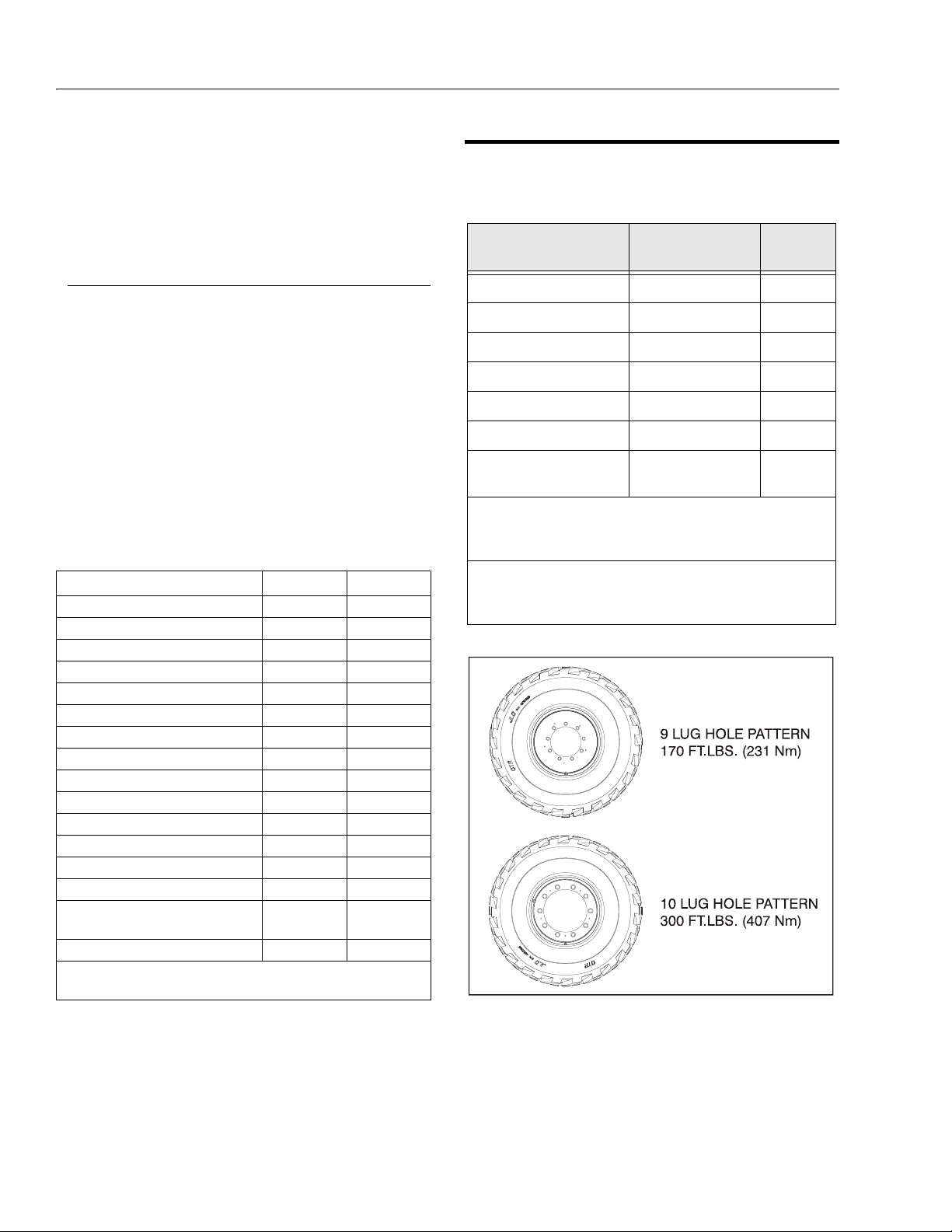
SECTION 1 - SPECIFICATIONS
Figure 1-1. 600S Lug Torques
Platform Rotate: Platform level and completely rotated
one direction. Rotate the opposite direction, Record Time.
Rotate the other direction, Record Time.
Articulating Jib: Platform level and centered with the
boom. Start with the Jib down. Jib Up, Record Time. Jib
Down, Record Time.
Te s t No te s
1. Stop watch should be started with the function, not
with the controller or switch.
2. All speed tests are run from the platform. These
speeds do not reflect the ground control operation.
3. The platform speed knob control must be at full
speed (turned clockwise completely).
4. Function speeds may vary due to cold, thick hydraulic oil. Test should be run with the oil temperature
above 100° F (38° C).
5. Some flow control functions may not work with the
speed knob clicked into the creep position.
Table 1-1. Function Speeds (In Seconds)
Function 600S 600A
Lift Up 46-60 26-32
Lift Down 33-43 26-32
Swing Right & Left* 79-101 79-101
Telescope Out 50-67 35-50
Telescope In 25-33 22-30
Platform Rotate Right & Lef t** 16-25 16-25
Jib Up 22-34 22-34
Jib Down 16-26 16-26
Lower Lift Up N.A. 37-50
Lower Lift Down N.A. 28-38
Lower Telescope Out N.A. 15-23
Lower Telescope In N.A. 09-15
Drive Forward & Reverse (2WD) 28-33 35-42
Drive Forward & Reverse (4WD) 31-37 31-37
Drive Above Horizontal - Forward &
Reverse (2WD & 4WD)
Drive Horizontal - Forward & Reverse N.A. 84-70
*Max 10% Difference Between Left & Right
**Max 15% Difference Between Left & Right
43-136 43-136
4150130 -E
1.5 TORQUE REQUIREMENTS
Table 1-2. Torque Requirements
Description To r q u e Valu e ( Dr y)
Bearing To Chassis See Note 50/600*
Bearing To Turntable See Note 50/600*
Wire Rope 15 ft. lbs (20 Nm) 150
Wheel Lugs (S Models) see Figure 1-1. 150
Wheel Lugs (A Models) 170 ft. lbs. (231 Nm) 150
Engine Mounting Bolts 165 f t. lbs. (231 Nm) A/R
Engine Manifold Mounting
Bolts
*Check swing bearing bolts for security after first 50 hours of operation and every 600 hours thereaf ter. (See Swing Bearing in Section
3.)
NOTE: When maintenance becomes necessary or a fastener
has loosened, refer to the Torque Chart to determine
proper torque value.
30 ft. lbs. (42 Nm) A/ R
Interval
Hours
1-4 – JLG Lift – 3120840
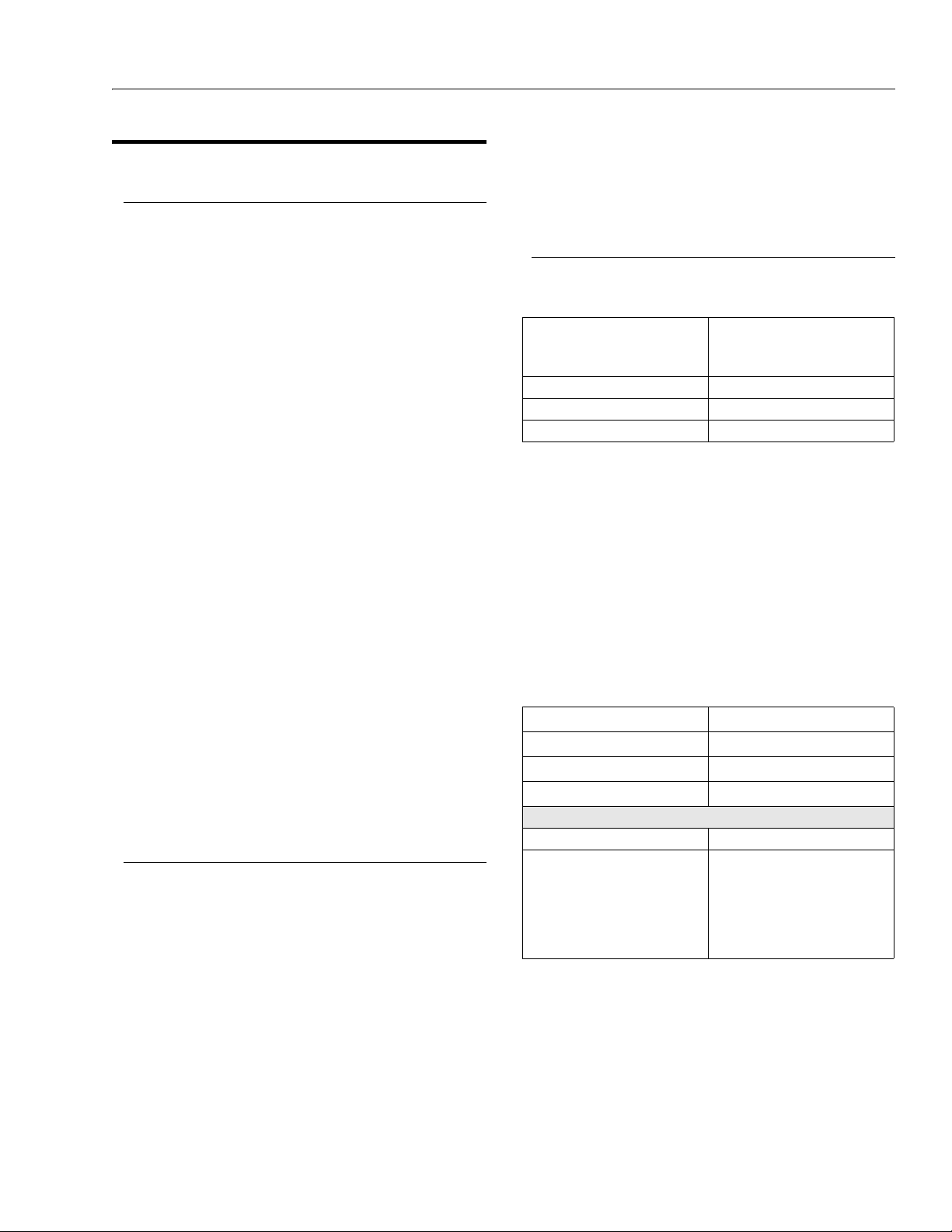
SECTION 1 - SPECIFICATIONS
1.6 LUBRICATION
Deutz F4M1011F Engine
Single Viscosity Oil (CD-SE, CD-SF).
When Outside Temperature is
Consistently
-20°F. to +25°F. (-29°C. to +4°C.) *10W
+5°F. to +50°F. (+15°C. to +10°C.) 20W-20
+40°F. to +85°F. (+4°C. to +30°C.) 30
Above 75°F. (24°C.) 40
Multi Viscosity Oil (CD-SE, CD-SF)
*This viscosity can be used at colder temperatures with
engine oil preheating.
When Outside
Tem pe ra t ur e is
Consistently
-40°F. to +75°F. (-40°C. to
+24°C.)
-15°F. to +70°F. (-26°C. to
+21°C.)
-15°F. to +85°F. (-26°C. to
+30°C.)
Above -5°F. (-21°C.) 15W-40
-5°F. to +75°F. (-21°C. to
+24°C.)
*This viscosity can be used at colder temperatures with
engine oil preheating.
NOTE: Crankcase oil should be MIL-L2104B/MIL-L2104C or
have properties of API classification CC/CD grades.
Use SAE Viscosity
Number
Use SAE Viscosity Number
*5W-30 (Synthetic)
10W-30
10W-40
15W-30
Continental TMD27 Engine
Single Viscosity Oils (CC-CD).
When Outside
Tem pe ra t ur e is
Consistently
+32°F. to +77°F. (+0°C. to
+25°C.)
Above +77°F. (+25°C.) 30
Below +32°F. (+0°C.) 10W
Multi Viscosity Oil (CC-CD)
*Not recommended for severe service, including high RPM
operation
Use SAE Viscosity Number
20
When Outside
Te m pe r at u re is
Consistently
Below +32°F. (+0°C.) 10W-30
Use SAE Viscosity Number
Hydraulic Oil
Table 1-3. Hydraulic Oil
HYDRAULIC SYSTEM
OPERATING
TEMPERATURE RANGE
-18° C to +83° C 10W
-18° C to +99° C 10W-20, 10W-30
+10° C to +210° C 20W-20
NOTE: Hydraulic oils must have anti-wear qualities at least
to API Service Classification GL-3, and sufficient
chemical stability for mobile hydraulic system service. JLG Industries recommends Mobilfluid 424
hydraulic oil, which has an SAE viscosity index of
152.
NOTE: When temperatures remain below 20° F (-7 degrees
C), JLG Industries recommends the use of Mobil
DTE 13M.
Table 1-4. Mobil DTE 13M Specs
ISO Viscosity Grade #32
Specific Gravity 0.877
Pour Point, Max -40°F (-40°C)
Flash Point, Min. 330°F (166°C)
at 40° C 33cSt
at 100° C 6.6 cSt
at 100° F 169 SUS
at 210° F 48 SUS
cp at -20° F 6,200
Viscosity Index 140
Aside from JLG recommendations, it is not advisable to
mix oils of different brands or types, as they may not contain the same required additives or be of comparable viscosities. If use of hydraulic oil other than Mobilfluid 424 is
desired, contact JLG Industries for proper recommendations.
SAE VISCOSITY GRADE
Viscosity
3120840 – JLG Lift – 1-5

SECTION 1 - SPECIFICATIONS
Lubrication Specifications
Table 1-5. Lubrication Specifications
KEY SPECIFICATIONS
MPG
EPGL
HO
EO
NOTE: Refer to Lubrication Chart, for specific lubrication
procedures.
Multipurpose Grease having a minimum dripping point of 350° F. Excellent water resistance and adhesive
qualities, and being of extreme pressure type.
(Timken OK 40 pounds minimum.)
Extreme Pressure Gear Lube (oil)
meeting API service classification
GL-5 or MIL- Spec MIL-L-2105
Hydraulic Oil. API service classification GL-3, e.g. Mobilfluid 424.
Engine (crankcase) Oil. Gas - API SF,
SH, SG class, MIL-L-2104. Diesel API CC/CD class, MIL-L-2104B/MILL-2104C.
1.7 PRESSURE SETTINGS
Rexroth Valve (S Models)
Main Relief - 207 Bar.
Upper Boom Lift Down - 103 Bar.
Swing - 117 Bar.
Steer - 124 Bar.
Steer Reliefs - 4WS Front & Rear - 172 Bar.
Platform Level Forward - 193 Bar.
Backward - 124 Bar.
Articulating Jib Boom Up - 103 Bar.
Down - 83 Bar.
Rexroth Valve (A Models)
Main Relief - 207 Bar.
Upper Boom Lift Down - 83 Bar.
Swing - 117 Bar.
Platform Level Forward - 193 Bar.
Backward - 124 Bar.
Steer - 124 Bar.
Steer Reliefs - 4WS Front & Rear - 172 Bar.
Articulating Jib Boom Up - 103 Bar.
Down - 83 Bar.
1-6 – JLG Lift – 3120840

SECTION 1 - SPECIFICATIONS
1.8 CYLINDER SPECIFICATIONS
Table 1-6. Cylinder Specifications (S Models)
DESRIPTON BORE STROKE ROD DIA.
600SJ 660SJ 600S 600SJ 660SJ 600S 600SJ 660SJ 600S
Lift 6.00
Tel e sc op e 3. 5
Steer 2.5
Lockout (2wd) 4
Master 3.5
Slave Level 3.5
Lift (Ar ticulating
Jib Boom)
(152.4)
(88.9)
(63.5)
(101.6)
(88.9)
(88.9)
(76.2)
DESRIPTON BORE STROKE ROD DIA.
Lower Lift 6.5
To we r T el es c op e 3
Upright Level 6
Upper Lift 4
Upper Telescope 3
Steer (2WD/2WSl 2.5
Steer (4WD/2WS) 2.5
Lockout (2WD) 3.5
Lockout (4WD 3.5
Master 3.5
Slave 3.5
Lift (Ar ticulating Jib Boom) 3
6.00
(152.4)
3.5
(88.9)
2.5
(63.5)
4
(101.6)
3.5
(88.9)
3.5
(88.9)
3
3
(76.2)
6.00
(152.4)
3.5
(88.9)
2.5
(63.5)
4
(101.6)
3
(76.2)
3
(76.2)
N/A 25.5
143.1875
44.6875
(1135.1)
(3637)
10.75
(273.1)
3.875
(98.4)
13.0625
(331.8)
13.0625
(331.8)
(647.7)
44.6875
(1135.1)
168.4375
(4278.3)
10.75
(273.1)
3.875
(98.4)
13.0625
(331.8)
13.0625
(331.8)
25.5
(647.7)
44.6875
(1135.1)
177.75
(4514.9)
10.75
(273.1)
3.875
(98.4)
8.5
(215.9)
8.5
(215.9)
N/A 1.5
3
(76.2)
2.5
(63.5)
1.25
(31.8)
1.5
(38.1)
1.5
(38.1)
1.5
(38.1)
(38.1)
3
(76.2)
2.5
(63.5)
1.25
(31.8)
1.5
(38.1)
1.5
(38.1)
1.5
(38.1)
1.5
(38.1)
3
(76.2)
2.5
(63.5)
1.25
(31.8)
1.5
(38.1)
1.5
(38.1)
1.5
(38.1)
N/A
Table 1-7. Cylinder Specifications (A Models)
600AJ 600A 600AJ 600A 600AJ 600A
(165.1)
(76.2)
(152.4)
(101.6)
(76.2)
(63.5)
(63.5)
(88.9)
(88.9)
(88.9)
(88.9)
(76.2)
6.5
(165.1)
3
(76.2)
6
(152.4)
4
(101.6)
3
(76.2)
2.5
(63.5)
2.5
(63.5)
3.5
(88.9)
3.5
(88.9)
3
(76.2)
3
(76.2)
N/A 25.5
34.0625
(865.2)
63.75
(1619.3)
34.625
(879.5)
36.625
(930.3)
134.375
(3413.1)
8.812
(204.7)
10.75
(273.1)
3.875
(98.4)
3.875
(98.4)
13.0625
(331.8)
13.0625
(331.8)
(647.7)
34.0625
(865.2)
63.75
(1619.3)
34.625
(879.5)
36.625
(930.3)
177.75
(4514.9)
8.812
(204.7)
10.75
(273.1)
3.875
(98.4)
3.875
(98.4)
8.5
(215.9)
8.5
(215.9)
N/A 1.5
2.5
(63.5)
2
(50.8)
3
(76.2)
2.5
(63.5)
2
(50.8)
1.25
(31.8)
1.25
(31.8)
2.5
(63.5)
2.5
(63.5)
1.5
(38.1)
1.5
(38.1)
(38.1)
2.5
(63.5)
2
(50.8)
3
(76.2)
2.5
(63.5)
2
(50.8)
1.25
(31.8)
1.25
(31.8)
2.5
(63.5)
2.5
(63.5)
1.5
(38.1)
1.5
(38.1)
N/A
3120840 – JLG Lift – 1-7
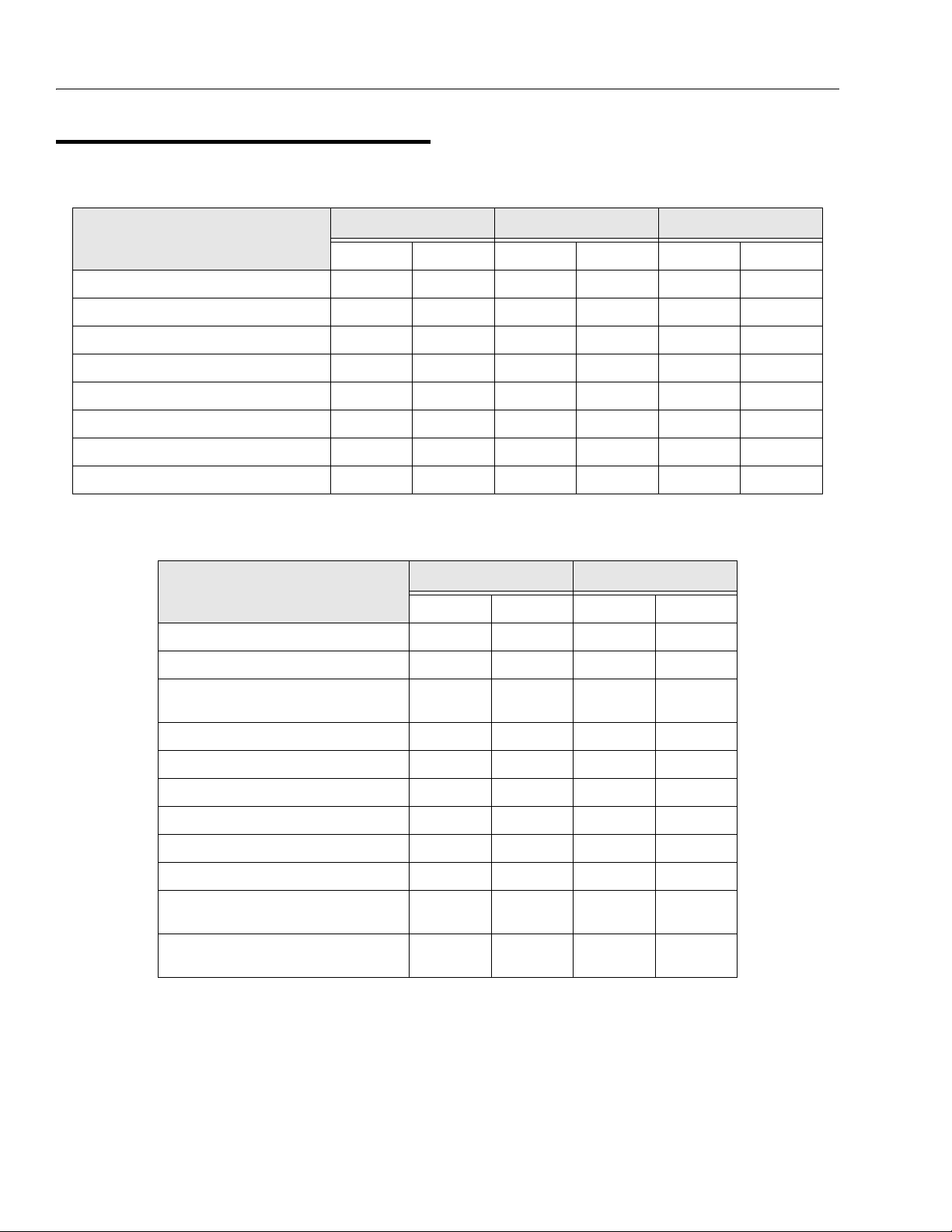
SECTION 1 - SPECIFICATIONS
1.9 MAJOR COMPONENT WEIGHTS
Table 1-8. Major Component Weights (S Models)
600SJ 660SJ 600S
LB. KG. LB. KG. LB. KG.
Platform Control Console 250 113 250 113 250 113
Platform Level Cylinder 60 27 60 27 46 21
Main Boom (Includes Lif t Cyl., Rotator, and Suppor t) 3483 1580 3783 1716 3527 1600
Turntable Complete (including engine) 7915 3590 90 65 4112 7315 3318
Chassis Complete (w/pneumatic tires) 11300 5126 11775 5341 10400 4718
Chassis Complete (w/foam-filled tires) 12580 5707 13055 5922 11680 5300
Machine Complete (GVW) - 2WD w/pneumatic tires 23500 10660 25500 11567 22000 9979
Machine Complete (GVW) - 4WD w/pneumatic tires 23980 10877 25910 11753 22510 1021 1
Table 1-9. Major Component Weights (A Models)
600AJ 600A
LB. KG. LB. KG.
Platform Control Console 250 113 250 113
Platform Level Cylinder 60 27 46 21
Main Boom (Includes Lift Cyl., Rotator, and Support)
Upright including Master Cylinder 547 248 547 2 48
Upright Level Cylinder 316 143 316 143
Tower Boom Complete 1218 553 1218 553
Turntable Complete (including engine) 9740 4418 9240 4191
Chassis Complete (w/pneumatic tires) 6834 310 0 6834 3100
Chassis Complete (w/foam-filled tires) 7918 359 2 7918 3592
Machine Complete (GVW) - 2WD w/pneumatic
tires
Machine Complete (GVW) - 4WD w/pneumatic
tires
1685 764 1832 831
22100 10025 20700 9390
22295 10113 21150 9594
1-8 – JLG Lift – 3120840
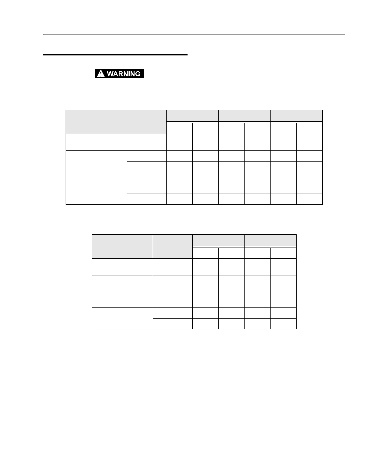
1.10 CRITICAL STABILITY WEIGHTS
SECTION 1 - SPECIFICATIONS
DO NOT REPLACE ITEMS CRITICAL TO STABILITY WITH
ITEMS OF DIFFERENT WEIGHT OR SPECIFICATION (FOR
Table 1-10. Critical Stability Weights (S Models)
Tire and Wheel (Ballasted
Only)
Engine Deutz 534 242 534 242 534 242
Counterweight Weight 3500 1588 4650 2109 2900 1315
Platform 6 f t. (1.83 M) 205 93 205 93 205 93
Size (15 - 19.5) 253 115 253 115 253 115
Continental 558 253 558 253 558 253
8 ft. (2.44 M) 230 105 230 105 230 105
Table 1-11. Critical Stability Weights (A Models)
EXAMPLE: BATTERIES, FILLED TIRES, COUNT
ENGINE & PLATFORM) DO NOT MODIFY UNIT IN ANY WAY TO
AFFECT STABILITY.
600SJ 660SJ 600S
LB. KG. LB. KG. LB. KG.
600AJ 600A
ERWEIGHT,
LB. KG. LB. KG.
Tire and Wheel (Ballasted
Only)
Engine Deutz 534 242 534 242
Counterweight Weight 6200 2812 5700 2586
Platform 6 f t. (1.83 M) 205 93 205 93
Size (14-17.5) 165 75 165 75
Continental 558 253 558 253
8 ft. (2.44 M) 230 105 230 105
3120840 – JLG Lift – 1-9
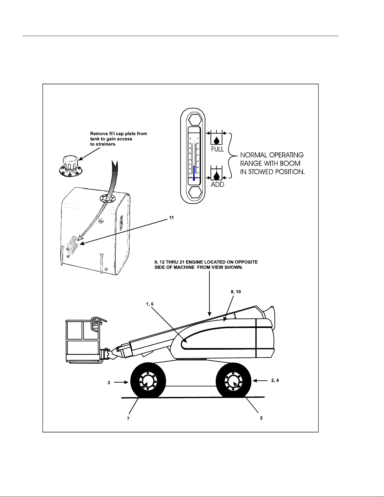
SECTION 1 - SPECIFICATIONS
Figure 1-2. Lubrication Point Location - S Models
1-10 – JLG Lift – 3120840
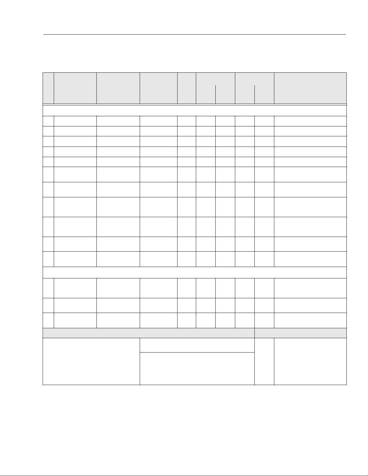
Components
Lubrication
Swing Bearing
1
Steer Spindles (2WS)*
2
Steer Spindles (4WS)*
3
Steer Spindles (4WD)*
4
Wheel Bearings
5
Swing Drive Hub
6
Wheel Drive Hub
7
Hydraulic Return Filter
8
Hydraulic Charge Filter
9
Hydraulic Oil
1
0
Suction Strainers (in tank)
1
1
SECTION 1 - SPECIFICATIONS
Table 1-12. Lubrication Chart - S Models
Interval Hours
Number/Type
Lube Points
2 Grease Fittings A/R MPG X Remote Access
8 Grease Fittings A/R MPG X
2 Grease Fittings A/R MPG X
4 Grease Fittings A/R MPG X
Repack A/R MPG X
Level/Fill Plug 0.5 liters (1/2 Full) EPGL X Check level every 150 hrs/change 1200
Level/Fill Plug 0.5 liters (1/2 Full) EPGL X Check level every 150 hrs/change 1200
N/A N/A N/A X Change after first 50 hrs. and every 300
N/A N/A N/A X Change after first 50 hrs. and every 300
Fill Cap 116 liters Tank
2 N/A N/A X Remove and clean at time of hydraulic oil
Capacity Lube
139 liters System
3
Months
150 hrs
6
Months
300 hrs
1 Year
600 hrs
2 Years
1200
hrs
Comments
hours
hours
hrs. thereafter or as indicated by Condition
Indicator.
hrs. thereafter or as indicated by Condition
Indicator.
HO X Check level daily/change 1200 hours
change.
Engines
Oil Change w/Filter - Deutz
1
2
Fuel Filter - Deutz
1
3
Air Filter - Deutz
1
4
NOTES: KEY TO LUBRICANTS
Lubrication intervals are based on ma chine operation under
normal conditions. For machin es used in multi shift operatio ns
and/or exposed to hostile en vironments or conditions, lubrication frequencies must be increased accordingly.
Fill Cap/Spin-on Ele-
ment
10.5 liters Crankcase
**4.5 liters Cooler
EO X Check level daily/Change in accordance
with engine manual.
Replaceable Element N/A N/A X
Replaceable Element N/A N/A X Or as indicated by Condition Indicator.
* Machines after S /N 38047 will have composite bushing s and no grease
fittings.
** When changing oil in the Deutz oil cooled engine, drain both the crankcase and the cooler. When refilling it is acceptable to over fill the crankcase
(16 liters, capacity of both crankcase and cooler combined). Star t engine,
allow the engine to run until the thermostat opens (approximately 105
degrees C) cooler will fill up within minutes; shut down and wait for approximately two minutes. Check oil level, fill oil to max marking on the dipstick.
EO
Engine Oil
EPGL
Extreme Pressure Gear Lube
HO
Hydraulic Fluid (Mobil #424 or equiva-
MPG
lent)
Multi-Purpose Grease
3120840 – JLG Lift – 1-11
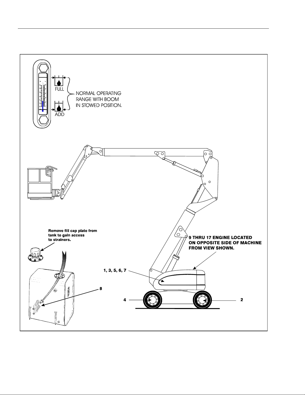
SECTION 1 - SPECIFICATIONS
Figure 1-3. Lubrication Point Location - A Models
1-12 – JLG Lift – 3120840
 Loading...