


JLG 26MRT Service Manual

SERVICE & MAINTENANCE
Model
26MRT
3120892
April 11, 2000
AUSTRALIAN OFFICE
JLG INDUSTRIES, INC.
P.O. Box 5119
11 Bolwarra Road
Port Macquarie, Australia
Telephone: 065 811111
Fax: 065 810122
EUROPEAN OFFICE
JLG INDUSTRIES (EUROPE)
Kilmartin Place,
Tannochside Park
Uddingston, Scotland, G71 5PH
Telephone: 01698 811005
Main Fax: 01698 811055
Parts Fax: 01698 811455
CORPORATE OFFICE
JLG INDUSTRIES, INC.
1 JLG Drive
McConnellsburg, PA.
17233-9533
USA
Telephone: (717) 485-5161
Fax: (717) 485-6417


INTRODUCTION - MAINTENANCE SAFETY PRECAUTIONS
SECTION A. INTRODUCT ION - MAINT ENA NCE SA FETY
PRECAUTIONS
A.A GENERAL
This section co nta ins the ge ne ra l s afet y pre cau tion s
which must b e ob serve d d uring mai ntena nce o f the
aerial platform. It i s of ut most i mport ance t hat m aintenance personnel pay strict attention to these warnings and precautions to avoid possible injury to
themselves or others, or damage to the equipment.
A maintenance prog ra m mus t be follo we d to e nsu re
that the machine is safe to operate.
MODIFICATION OF THE MACHINE WITHOUT CERTIFICATION BY A RESPONSIBLE AUTHORITY THAT THE
MACHINE IS AT LEAST AS SAFE AS ORIGINALLY
MANUFACTURED, IS A SAFETY VIOLATION.
The specific precautions to be observed du ring
maintenance are inserted at the appropriate point in
the manual. The se precaution s are, for the m ost
part, those that apply when servicing hydraulic and
larger machine component parts.
Your safety, and that of others, is the first consideration when engaging in the maintenance of equipment. Always be conscious of weight. Never attempt
to move heavy parts without the aid of a mechanic al
device. Do not allow heavy objects to rest in an
unstable position. When raising a portion of the
equipment, ensure that adequate support is provided.
SINCE THE MACHINE MANUFACTURER HAS NO
DIRECT CONTROL OVER THE FIELD INSPECTION
AND MAINTENANCE, SAFETY IN THIS AREA RESPONSIBILITY OF THE OWNER/OPERATOR.
A.B HYDRAULIC SYSTEM SAFETY
It should be noted that the machines hydraulic systems operate at extremely high potentially dangerous pressures. Every effort should be made to
relieve any syst em pressu re pri or to disc onnecting
or removing any portion of the system.
Relieve system pressure by cycling the applicable
control several times with the engine stopped and
ignition on, to direct any line pressure back into the
reservoir. Pressure feed lines to system components
can then be disconnected with minimal fluid loss.
A.C MAINTENANCE
FAILURE TO COMPLY WITH SAFETY PRECAUTIONS
LISTED IN T HIS SECTIO N MAY RESULT IN MACHINE
DAMAGE, PERSONNEL INJURY OR DEATH AND IS A
SAFETY VIOLATION.
• NO SMOKING IS MANDATORY. NEVER REFUEL DURING ELECTRICAL STORMS. ENSU RE TH AT FUEL CAP
IS CLOSED AND SECURE AT ALL OTHER TIMES.
• REMOVE ALL RINGS, WATCHES AND JEWELRY
WHEN PERFORMING ANY MAINTENANCE.
• DO NOT WEAR LONG HAIR UNRESTRAINED, OR
LOOSE-FITTING CLOTHING AND NECKTIES WHICH
ARE APT TO BECOME CAUGHT ON OR ENTANGLED
IN EQUIPMENT.
• OBSERVE AND OBEY ALL WARNINGS AND CAUTIONS ON MACHINE AND IN SERVICE MANUAL.
• KEEP OIL, GREASE, WATER, ETC. WIPED FROM
STANDING SURFACES AND HAND HOLDS.
• USE CAUTION WHEN CHECKING A HOT, PRESSURIZED COOLANT SYSTEM.
• NEVER WORK UNDER AN ELEVATED BOOM UNTIL
BOOM HAS BEEN SAFELY RESTRAINED FROM ANY
MOVEMENT BY BLOCKING OR OVERHEAD SLING,
OR BOOM SAFETY PROP HAS BEEN ENGAGED.
• BEFORE MAKING ADJUSTMENTS, LUBRICATING OR
PERFORMING ANY OTHER MAINTENANCE, SHUT
OFF ALL POWER CONTROLS.
• BATTERY SHOULD ALWAYS BE DISCONNECTED
DURING REPLACEMENT OF ELECTRICAL COMPONENTS.
• KEEP ALL SUPPORT EQUIPMENT AND ATTACHMENTS STOWED IN THEIR PROPER PLACE.
• USE ONLY APPROVED, NONFLAMMABLE CLEANING
SOLVENTS.
3120892 – JLG Sizzor – a

INTRODUCTION - MAINTENANCE SAFETY PRECAUTIONS
REVISON LOG
Original Issue - Apri l 11, 2000
(This manual split from manual 3120844)
b – JLG Sizzor – 3120892

TABLE OF CONTENTS
TABLE OF CONTENTS
SUBJECT - SECTION, PARAGRAPH PAGE NO.
SECTION A - INTRODUCTION - MAINTENANCE SAFE TY PRECAUTIONS
A.A General . . . . . . . . . . . . . . . . . . . . . . . . . . . . . . . . . . . . . . . . . . . . . . . . . . . . . . . . . . . . . . . . . . . . . .a
A.B Hydraulic System Safety. . . . . . . . . . . . . . . . . . . . . . . . . . . . . . . . . . . . . . . . . . . . . . . . . . . . . . . . .a
A.C Maintenance . . . . . . . . . . . . . . . . . . . . . . . . . . . . . . . . . . . . . . . . . . . . . . . . . . . . . . . . . . . . . . . . . .a
SECTION 1 - SPECIFI C ATIONS
1.1 Capacities . . . . . . . . . . . . . . . . . . . . . . . . . . . . . . . . . . . . . . . . . . . . . . . . . . . . . . . . . . . . . . . . . . . .1-1
1.2 Component Data. . . . . . . . . . . . . . . . . . . . . . . . . . . . . . . . . . . . . . . . . . . . . . . . . . . . . . . . . . . . . . .1-1
1.3 Performance Data . . . . . . . . . . . . . . . . . . . . . . . . . . . . . . . . . . . . . . . . . . . . . . . . . . . . . . . . . . . . . .1-1
1.4 Torque Requirements . . . . . . . . . . . . . . . . . . . . . . . . . . . . . . . . . . . . . . . . . . . . . . . . . . . . . . . . . . .1-2
1.5 Lubrication. . . . . . . . . . . . . . . . . . . . . . . . . . . . . . . . . . . . . . . . . . . . . . . . . . . . . . . . . . . . . . . . . . . .1-2
1.6 Cylinder Specifications . . . . . . . . . . . . . . . . . . . . . . . . . . . . . . . . . . . . . . . . . . . . . . . . . . . . . . . . . . 1-3
1.7 Pressure Settings . . . . . . . . . . . . . . . . . . . . . . . . . . . . . . . . . . . . . . . . . . . . . . . . . . . . . . . . . . . . . .1-3
1.8 Serial Number Locations. . . . . . . . . . . . . . . . . . . . . . . . . . . . . . . . . . . . . . . . . . . . . . . . . . . . . . . . .1-3
1.9 Limit Switches . . . . . . . . . . . . . . . . . . . . . . . . . . . . . . . . . . . . . . . . . . . . . . . . . . . . . . . . . . . . . . . . .1-3
1.10 Major Component Weights. . . . . . . . . . . . . . . . . . . . . . . . . . . . . . . . . . . . . . . . . . . . . . . . . . . . . . .1-3
1.11 Critical Stability Weights . . . . . . . . . . . . . . . . . . . . . . . . . . . . . . . . . . . . . . . . . . . . . . . . . . . . . . . . .1-3
SECTION 2 - PROCEDURES
2.1 General . . . . . . . . . . . . . . . . . . . . . . . . . . . . . . . . . . . . . . . . . . . . . . . . . . . . . . . . . . . . . . . . . . . . . .2-1
2.2 Servicing and Maintenance Guidelines . . . . . . . . . . . . . . . . . . . . . . . . . . . . . . . . . . . . . . . . . . . . .2-1
2.3 Lubrication Information . . . . . . . . . . . . . . . . . . . . . . . . . . . . . . . . . . . . . . . . . . . . . . . . . . . . . . . . . .2-2
2.4 Cylinders - Theory of Operation . . . . . . . . . . . . . . . . . . . . . . . . . . . . . . . . . . . . . . . . . . . . . . . . . . . 2-3
2.5 Valves - Theory of Operation. . . . . . . . . . . . . . . . . . . . . . . . . . . . . . . . . . . . . . . . . . . . . . . . . . . . . .2-3
2.6 Component Functional Description . . . . . . . . . . . . . . . . . . . . . . . . . . . . . . . . . . . . . . . . . . . . . . . .2-4
2.7 Wear Pads . . . . . . . . . . . . . . . . . . . . . . . . . . . . . . . . . . . . . . . . . . . . . . . . . . . . . . . . . . . . . . . . . . . .2-4
2.8 Cylinder Checking Procedures. . . . . . . . . . . . . . . . . . . . . . . . . . . . . . . . . . . . . . . . . . . . . . . . . . . .2-4
2.9 Lift Cylinder Removal and Installation. . . . . . . . . . . . . . . . . . . . . . . . . . . . . . . . . . . . . . . . . . . . . . .2-5
2.10 Lift Cylinder Repair . . . . . . . . . . . . . . . . . . . . . . . . . . . . . . . . . . . . . . . . . . . . . . . . . . . . . . . . . . . . .2-5
2.11 Steer Cylinder Repair . . . . . . . . . . . . . . . . . . . . . . . . . . . . . . . . . . . . . . . . . . . . . . . . . . . . . . . . . . .2-10
2.12 Tilt Alarm Switch Adjustment (If Equipped) . . . . . . . . . . . . . . . . . . . . . . . . . . . . . . . . . . . . . . . . .2-12
2.13 Limit Switch Adjustment . . . . . . . . . . . . . . . . . . . . . . . . . . . . . . . . . . . . . . . . . . . . . . . . . . . . . . . . .2-13
2.14 Pressure Setting Procedures . . . . . . . . . . . . . . . . . . . . . . . . . . . . . . . . . . . . . . . . . . . . . . . . . . . . .2-13
2.15 Drive Axle Repair. . . . . . . . . . . . . . . . . . . . . . . . . . . . . . . . . . . . . . . . . . . . . . . . . . . . . . . . . . . . . . .2-14
2.16 Brake Repair . . . . . . . . . . . . . . . . . . . . . . . . . . . . . . . . . . . . . . . . . . . . . . . . . . . . . . . . . . . . . . . . . .2-23
2.17 Throttle Checks and Adjustments. . . . . . . . . . . . . . . . . . . . . . . . . . . . . . . . . . . . . . . . . . . . . . . . . .2-26
2.18 Control Card Setup and Test Procedures. . . . . . . . . . . . . . . . . . . . . . . . . . . . . . . . . . . . . . . . . . .2-26
2.19 Valve Driver Card Setup Procedure . . . . . . . . . . . . . . . . . . . . . . . . . . . . . . . . . . . . . . . . . . . . . . . .2-29
2.20 Preventive Maintenance and Inspection Schedule. . . . . . . . . . . . . . . . . . . . . . . . . . . . . . . . . . . . .2-31
SECTION 3 - TROU BL ESHOOTING
3.1 General . . . . . . . . . . . . . . . . . . . . . . . . . . . . . . . . . . . . . . . . . . . . . . . . . . . . . . . . . . . . . . . . . . . . . .3-1
3.2 Troubleshooting Information. . . . . . . . . . . . . . . . . . . . . . . . . . . . . . . . . . . . . . . . . . . . . . . . . . . . . .3-1
3.3 Hydraulic Circuit Checks. . . . . . . . . . . . . . . . . . . . . . . . . . . . . . . . . . . . . . . . . . . . . . . . . . . . . . . . .3-1
3120892 – JLG Sizzor – i

TABLE OF CONTENTS
LIST OF FIGURES
FIGURE NO. TITLE PAGE NO.
1-1. Lubrication Diagram . . . . . . . . . . . . . . . . . . . . . . . . . . . . . . . . . . . . . . . . . . . . . . . . . . . . . . . . . . . .1-4
1-2. Serial Number Locations. . . . . . . . . . . . . . . . . . . . . . . . . . . . . . . . . . . . . . . . . . . . . . . . . . . . . . . . .1-5
1-3. Torque Chart . . . . . . . . . . . . . . . . . . . . . . . . . . . . . . . . . . . . . . . . . . . . . . . . . . . . . . . . . . . . . . . . . .1-6
2-1. Barrel Support. . . . . . . . . . . . . . . . . . . . . . . . . . . . . . . . . . . . . . . . . . . . . . . . . . . . . . . . . . . . . . . . .2-6
2-2. Cap Screw Removal . . . . . . . . . . . . . . . . . . . . . . . . . . . . . . . . . . . . . . . . . . . . . . . . . . . . . . . . . . . .2-6
2-3. Rod Support . . . . . . . . . . . . . . . . . . . . . . . . . . . . . . . . . . . . . . . . . . . . . . . . . . . . . . . . . . . . . . . . . .2-6
2-4. Tapered Bushing Removal . . . . . . . . . . . . . . . . . . . . . . . . . . . . . . . . . . . . . . . . . . . . . . . . . . . . . . .2-6
2-5. Rod Seal Installation . . . . . . . . . . . . . . . . . . . . . . . . . . . . . . . . . . . . . . . . . . . . . . . . . . . . . . . . . . . .2-7
2-6. Poly-Pak Seal Installation . . . . . . . . . . . . . . . . . . . . . . . . . . . . . . . . . . . . . . . . . . . . . . . . . . . . . . . .2-8
2-7. Wiper Seal Installation. . . . . . . . . . . . . . . . . . . . . . . . . . . . . . . . . . . . . . . . . . . . . . . . . . . . . . . . . . .2-8
2-8. Head Seal Kit Installation . . . . . . . . . . . . . . . . . . . . . . . . . . . . . . . . . . . . . . . . . . . . . . . . . . . . . . . .2-8
2-9. Piston Seal Kit. . . . . . . . . . . . . . . . . . . . . . . . . . . . . . . . . . . . . . . . . . . . . . . . . . . . . . . . . . . . . . . . .2-8
2-10. Tapered Bushing Installation . . . . . . . . . . . . . . . . . . . . . . . . . . . . . . . . . . . . . . . . . . . . . . . . . . . . .2-9
2-11. Rod Assembly Installation. . . . . . . . . . . . . . . . . . . . . . . . . . . . . . . . . . . . . . . . . . . . . . . . . . . . . . . .2-9
2-12. Ste e r Cyl inder Assembly. . . . . . . . . . . . . . . . . . . . . . . . . . . . . . . . . . . . . . . . . . . . . . . . . . . . . . . . .2 -10
2-13. Tilt Switch Leveling - Manual Adjustment . . . . . . . . . . . . . . . . . . . . . . . . . . . . . . . . . . . . . . . . . . . .2-12
2-14. Tilt Switch Leveling - Voltmeter Adjustment . . . . . . . . . . . . . . . . . . . . . . . . . . . . . . . . . . . . . . . . . .2-13
2-15. Valve Components . . . . . . . . . . . . . . . . . . . . . . . . . . . . . . . . . . . . . . . . . . . . . . . . . . . . . . . . . . . . .2-14
2-16. Drive Axle Assembly . . . . . . . . . . . . . . . . . . . . . . . . . . . . . . . . . . . . . . . . . . . . . . . . . . . . . . . . . . . .2-16
2-17. Carrier Section. . . . . . . . . . . . . . . . . . . . . . . . . . . . . . . . . . . . . . . . . . . . . . . . . . . . . . . . . . . . . . . . .2-21
2-18. Ri ng G ear and Pinion Tooth Contact Patte rn . . . . . . . . . . . . . . . . . . . . . . . . . . . . . . . . . . . . . . . . .2-22
2-19. Ring Gear Pattern Interpretation. . . . . . . . . . . . . . . . . . . . . . . . . . . . . . . . . . . . . . . . . . . . . . . . . . .2-23
2-20. Brake Assembly. . . . . . . . . . . . . . . . . . . . . . . . . . . . . . . . . . . . . . . . . . . . . . . . . . . . . . . . . . . . . . . .2-25
2-21. ADDCO Adjustments (Gasoline/Dual Fuel Engine) . . . . . . . . . . . . . . . . . . . . . . . . . . . . . . . . . . . .2-27
2-22. ADDCO Adjustments (Diesel Engine). . . . . . . . . . . . . . . . . . . . . . . . . . . . . . . . . . . . . . . . . . . . . . .2-28
2-23. Valve Driver Card. . . . . . . . . . . . . . . . . . . . . . . . . . . . . . . . . . . . . . . . . . . . . . . . . . . . . . . . . . . . . . .2-29
3-1. Electrical Schematic - Yanmar (Sheet of 1 of 2) . . . . . . . . . . . . . . . . . . . . . . . . . . . . . . . . . . . . . .3-10
3-2. Electrical Schematic - Yanmar (Sheet of 2 of 2) . . . . . . . . . . . . . . . . . . . . . . . . . . . . . . . . . . . . . .3-11
3-3. Electrical Schematic - Da ihatsu (Sheet 1 of 2) . . . . . . . . . . . . . . . . . . . . . . . . . . . . . . . . . . . . . . . .3-12
3-4. Electrical Schematic - Da ihatsu (Sheet 2 of 2) . . . . . . . . . . . . . . . . . . . . . . . . . . . . . . . . . . . . . . . .3-13
3-5. Hydraulic Schematic (Sheet 1 of 2) . . . . . . . . . . . . . . . . . . . . . . . . . . . . . . . . . . . . . . . . . . . . . . . .3-14
3-6. Hydraulic Schematic (Sheet 2 of 2) . . . . . . . . . . . . . . . . . . . . . . . . . . . . . . . . . . . . . . . . . . . . . . . .3-15
LIST OF TABLES
TABLE NO. TITLE PAGE NO.
1-1 Hydraulic Oil . . . . . . . . . . . . . . . . . . . . . . . . . . . . . . . . . . . . . . . . . . . . . . . . . . . . . . . . . . . . . . . . . .1-2
1-2 Lubrication Specifications. . . . . . . . . . . . . . . . . . . . . . . . . . . . . . . . . . . . . . . . . . . . . . . . . . . . . . . .1-3
1-3 Cylinder Specificat ions . . . . . . . . . . . . . . . . . . . . . . . . . . . . . . . . . . . . . . . . . . . . . . . . . . . . . . . . . .1-3
1-4 Major Component Weights. . . . . . . . . . . . . . . . . . . . . . . . . . . . . . . . . . . . . . . . . . . . . . . . . . . . . . .1-3
1-5 Critical Stability Weights . . . . . . . . . . . . . . . . . . . . . . . . . . . . . . . . . . . . . . . . . . . . . . . . . . . . . . . . .1-3
1-6 Lubrication Chart . . . . . . . . . . . . . . . . . . . . . . . . . . . . . . . . . . . . . . . . . . . . . . . . . . . . . . . . . . . . . . .1-4
2-1 Cylinder Component To r que Specificat ions. . . . . . . . . . . . . . . . . . . . . . . . . . . . . . . . . . . . . . . . . .2-9
2-2 Holding Valve Torque Specifications . . . . . . . . . . . . . . . . . . . . . . . . . . . . . . . . . . . . . . . . . . . . . . .2-9
2-3 Preventive Maintenanc e and Safety Inspect ion . . . . . . . . . . . . . . . . . . . . . . . . . . . . . . . . . . . . . . .2-32
3-1 Elevation System Troubleshooting. . . . . . . . . . . . . . . . . . . . . . . . . . . . . . . . . . . . . . . . . . . . . . . . .3-2
3-2 Chassis Troubleshooting . . . . . . . . . . . . . . . . . . . . . . . . . . . . . . . . . . . . . . . . . . . . . . . . . . . . . . . .3-4
3-3 Hydraulic System Troubleshooting. . . . . . . . . . . . . . . . . . . . . . . . . . . . . . . . . . . . . . . . . . . . . . . . .3-7
3-4 Electrical System Troubleshooting. . . . . . . . . . . . . . . . . . . . . . . . . . . . . . . . . . . . . . . . . . . . . . . . .3-8
ii – JLG Sizzor – 3120892

SECTION 1 - SPECIFICATIONS
SECTION 1. SPECIFICATIONS
1.1 CAPACITIES
Hydraulic Oil Tank
56.8 liters (15.0 gallons)
Hydraulic System (Including Tank)
Approximately 68.1 liters (18.0 gallons)
Fue l Tank
29.5 liters (7.8 gallons)
Drive Axle
6.4 liters (3 pints)
1.2 COMPONENT DATA
Engine
Daihatsu Gasoline/LP
3 cylinder, liquid-cooled
21 horsepower @ 3,000 rpm
Idle - 1,500 rpm
Mid Engine - 2,000 rpm
High Engine - 3,000 rpm
Alternator - 14 Amp
Cooling System Capacit y
Drive Pump
Closed loop piston type
Output - 56.8 lpm (15 gpm) @ 3,000 rpm
Displacement - 19.0 cm3/rev. (1.16 in.3/rev.)
Lift/Steer Pump
Gear type
Output - 11.7 lpm (3.1 gpm) @ 3,000 rpm.
Displacement - 4.0 cm3/rev. (0.24 in.3/rev.).
Steer/Drive System
Steer (Front) Tires - Dico Multi-Trac C/S 26 x 12.00 - 12
NHS; 6 ply; inflate to 2.8 bar (40 psi).
Toe-In - Adjust to 6.4 mm (.25 in) overall.
Drive (Rear) Tires - Dico Tru-Power TL 26 x 12.00 - 12
NHS; 6 ply; inflate to 2.8 bar (40 psi).
Drive Brake - Mico hydraulic multi-disc.
Drive Motor - Eaton 2000 Series; 13 1 cm3/rev. (8.0 in.3/
rev.).
Drive Axle - Dana Model 44 rigid semi-float, no spin axle
assembly; 5.89 ratio; oil capacity - 1.4 liters (3 pints).
Hydraulic Filter - Inline
Return - Bypass Type
10 Microns Nominal
Engine - 1.8 liters (1.9 quarts)
Crankcase Capacity - 3.0 liters (3.2 quarts)
Yanmar Diesel
3 cylinder, liquid-cooled
22 horsepower @ 3,000 rpm
Idle - 1,200 rpm
Mid Engine - 2,000 rpm
High Engine - 3,000 rpm
Alternator - 40 Amp
Cooling System Capacit y
0.9 liters (1.0 quarts) - engine
Crankcase Capacity - 2.4 liters (2.5 quarts)
Platform Size
Standard - 1.4 m x 2.2 m (54 in. x 88 in.)
1.3 PERFORMANCE DATA
Travel Speed
Maximum Speed - 7.2 kmh (4.5 mph)
Elevated Speed - 1.1 kmh (0.7 mph)
Gradeability
35%
Turning Radius
Inside - 2.5 m (8 f t . 1 in.)
Outside - 4.7 m (15 ft. 4 in.)
3120892 – JLG Sizzor – 1-1
SECTION 1 - SPECIFICATIONS
Lift
Up - 34-42 seconds
Down - 31-39 seconds
Platform Capacity
Standard - 455 kg (1,000 lb.)
Manual Platform Extension Capacity
115 kg (250 lb.)
Machine Weight
Approximately 2359 kg (5,200 lb.)
Wheelbase
2.0 m (78.0 in.)
Machine Height (Platform Fully Elevated)
7.9 m (26 ft.)
Machine Height (Platform Lowered)
2.3 m (89.0 in.)
Platform Railing Height
1.0 m (39.5 in.)
1.5 LUBRICATION
Hydraulic Oil
Table 1-1. Hydraulic Oil
HYDRAULIC SYSTEM OPERATING
TEMPERATURE RANGE
0 to +23 degrees F
(-18 to -5 degrees C)
0 to +210 degrees F
(-18 to +100 degrees C)
+50 to +210 degrees F
(+10 to +100 degrees C)
NOTE: Hydraulic oils must have anti-wear qualities at least
to API Service Classification GL-3, and sufficient
chemical stability for mobile hydraulic system service. JLG Industries recommends Mobilfluid 424
hydraulic oil, which has an SAE viscosity of 10W-30
and a viscosity index of 152.
Aside from JLG recom men da tion s , it is not advisabl e
to mix oils of different brands or types, as they may
not contain the same required additives or be of
comparable visc osities. If use of hydraulic oil other
than Mobilfluid 424 is desired, contact JLG Industries for proper recommendations.
SAE VISCOSITY GRADE
10W
10W-20,10W-30
20W-20
Machine Length
2.7 m (105.0 in.)
Machine Width
1.8 m (69.0 in.)
Ground Clearance
14.0 cm (5.5 in.)
Maximum Tire Load
921 kg (2,030 lb.) @ 1.3 bar (19 psi)
1.4 TORQUE REQUIREMENTS
All wheel lug nuts should be torqued to 122 Nm (90 ft lb)
every 150 hours.
NOTE: When maintenance becomes necessary or a fas-
tener has l oosen ed, re fer to the To rque Char t i n this
section to determine proper torque value.
1-2 – JLG Sizzor – 3120892

SECTION 1 - SPECIFICATIONS
Lubrication Specifications
1.6 CYLINDER SPECIFICATIONS
Table 1-2. Lubrication Specifications
KEY SPECIFICATIONS
MPG Multipurpose Grease having a minimum dripping
point of 350 degress F. Excellent water resistance
and adhesive qualities, and being of extreme pres-
sure type. (Timken OK 40 pounds minimum.)
EPGL Extreme Pressure Gear Lube (oil) meeting API ser-
vice classification GL-5 or MIL-Spec MIL-L-2105.
EO Engin e (crankcase) Oil. Gas - A PI SF/SG class, MIL-
L-2104. Diesel - API CC/CD class, MIL-L-2104B/
MIL-L-2104C.
HO Hydraulic Oil. API service classification GL-3, e.g.
Mobil 424.
NOTE: All dimensions are given in inches (in), with the met-
ric equivalent, centimeters (cm), given in parentheses.
1.8 SERIAL NUMBER LOCATIONS
For machine identification, a serial number plate is affixed
to the machine. The plate is l ocated o n the re ar center of
the machine frame, just below the middle step of the ladder. In addition, if the serial number plate is damaged or
missing, the machine serial number is stamped on the
right front frame rail, adjacent to the sizzor arms.
1.9 LIMIT SWITCHES
The machine is equipped with the following limit switches:
Tilt Alarm (Optional) - 5° - Illuminates a light on the platform and sounds an alarm when the machine is 5° out of
level in any direction.
High Drive Cut-Out - High drive speed is cut out when the
platform is raised above the stowed position.
1.10 MAJOR COMPONENT WEIGHTS
Table 1-4. Major Component Weights
Table 1-3. Cylinder Specifications
Description Bore Stroke Rod Dia.
Lift Cylinder 4.00
(10.2)
Steer Cylinder
(DoubleRrod)
2.00
(5.1)
39.75
(101.0)
2.69
(6.83)
1.7 PRESSURE SETTINGS
Main Relief - 145 bar (2100 psi)
Steer Relief - 103 bar (1500 psi)
Lift Up Relief - 145 bar (2100 psi)
Lift Down Relief - 62 bar (900 psi)
2.50
(6.4)
1.25
(3.18)
Component lb kg
Platform 382 173
Manual Platform Extension 221 100
Arm Assembly (Includes Lift Cylinder) 1618 734
Chassis - w/Standard Tires 2979 1351
1.11 CRITICAL STABILITY WEIGHTS
DO NOT REPLACE ITE MS CRITICAL TO STABILITY, SUCH AS
ENGINES, AXLES OR TIRES, WITH ITE MS OF DIFFERENT
WEIGHT OR SPECIFICATION. DO NOT MODIFY UNIT IN ANY WAY
TO AFFECT STABILITY.
Table 1-5. Critical Stability Weights
Component lb kg
Tire and Wheel Assembly - Std (each) 50 23
Daihatsu Gasoline/LP Engine 132 60
Yanmar Diesel Engine 183 81
Dana Drive Axle 130 59
3120892 – JLG Sizzor – 1-3

SECTION 1 - SPECIFICATIONS
Figure 1-1. Lubrication Diagram
Table 1-6. Lubrication Chart
INDEX
NO
1 Wheel Bearings 2- Front Wheels MPG - repack 1200
2 Hydraulic Oil Fill Cap/Drain Plug HO - Check HO Level
3 Hydraulic Return Filter N/A N/A 50/300
4 Charge Pump Filter N/A N/A 50/300
5 Crankcase - Vanguard Gasoline/LP
6 Crankcase - Yanmar Diesel Engine FillCap/Drain Plug EO - Check EO Level
7 Rear Axle FillCap/Drain Plug EPGL - Check EPGL Level
KEY TO LUBRICANTS:
EO - Engine Oil
EPGL - Extreme Pressure Gear Lubricant
HO - Hydraulic Oil - Mobilfluid 424
MPG - Multi-purpose Grease
COMPONENT NUMBER/TYPE LUBE POINTS LUBE METHODS
HO - Change HO
FillCap/Drain Plug EO - Check EO Level
Engine
EO - Change EO
EO - Change EO
EPGL - Change EPGL
NOTE: 1. B e sure to lu bricate like items on each side.
2. Recommended lubricating intervals are based
on maching operations under normal conditions.
For machines used in multi-shift operations and/or
exposed to hostile environments or conditions,
lubrication frequencies must be increased accordingly.
3. Operate hydraulic functions through one complete cycle before checking hydraulic oil level in
tank. Oil sh oul d b e vis ible i n AD D s ight wi ndow o n
TO AVOID PERSONAL INJURY, USE SAFETY PROP FOR ALL
MAINTENANCE REQUIREING PLATFORM TO BE ELEVATED.
hydraulic tank. If oil is not visible, add oil until oil is
visible in both ADD and FULL sight windows on
tank. Do not overfill tank.
INTERVAL
HOURS
Daily/1200
Daily/50/30 0
Daily/50/30 0
150/1200
1-4 – JLG Sizzor – 3120892

SECTION 1 - SPECIFICATIONS
Figure 1-2. Serial Number Locati ons
3120892 – JLG Sizzor – 1-5

SECTION 1 - SPECIFICATIONS
Figure 1-3. Torque Chart
1-6 – JLG Sizzor – 3120892

SECTION 2. PROCEDURES
SECTION 2 - PROCEDURES
2.1 GENERAL
This section provides information necessary to per form
maintenance on the scissor lif t. Description s, techni ques
and specific procedures are designed to provide the safest and most ef fici ent main tenance for use b y person nel
responsible for ensuring the correct installation and operation of machine components an d systems.
WHEN AN ABNORMAL CONDITION IS NOTED AND PROCEDURES
CONTAINED HEREIN DO NOT SPECIFICALLY RELATE TO THE
NOTED IRREGULARITY, WORK SHOULD BE STOPPED AND
TECHNICALLY QUALIFIED GUIDAN CE OBTAINED BEFORE
WORK IS RESUMED.
The maintenance procedures included consist of servicing and component removal and installation, disassembly
and assembly, inspection, lubrication and cleaning. Information on any special tools or test equipment is also provided where applicable.
2.2 SERVICING AND MAINTENANCE
GUIDELINES
General
The following inf ormation is prov ided to a ssist you in t he
use and application of servicing and maintenance procedures contained in this chapter.
Safety and Workmanship
Your s afety, and that of others, is the first conside ration
when engaging in the maintenance of equipment. Always
be conscious of weight. Never atte mpt to move heavy
parts without the aid of a mechanical device. Do not allow
heavy objects to rest in an unstable position. When raising
a portion of the equipment, ensure that ad equate support
is provided.
and fittings themselves. As soon as a line or component is disconnected, cap or cover all openings to
prevent entry of foreign matter.
3. Clean and inspect all parts during servicing or maintenance, and assure that all passages and openings
are unobstructed. Cover all parts to keep them
clean. Be sure all parts are clean before they are
installed. New parts should remain in their containers until they are ready to be used.
Components Removal and Installation
4. Use adjustable lifting devices, whenever possible, if
mechanical assistance is required. All slings (chains,
cables, etc.) should be parallel to each other and as
near perpend icular as possibl e to top of par t being
lifted.
5. Should it be necessary to remove a c omponent on
an angle, keep in mind that the capacity of an eyebolt or similar bracket lessens, as th e an gle between
the supporting structure and the component
becomes less than 90°.
6. If a part resists removal, check to see whether all
nuts, bolts, ca bles, br acke ts, wir ing, et c., have been
removed and that no adjacent parts are interfering.
Component Disassembly and Reassembly
When disassembling or r e assembling a comp on ent, complete the procedural steps in sequence. Do not part ially
disassemble or assemble one part, then start on another.
Always recheck your work to assure that nothing has been
overlooked. Do not make any adjustments, ot her than
those recommended, without obtaining proper approval.
Pressure-Fit Parts
When assembling pressure-fit parts, use an “anti-seize” or
molybdenum disulfid e base co mpound to l ubricate the
mating surface.
Cleanliness
1. The most important single item in preserving the
long service life of a machine is to keep dirt and foreign materials out of the vital components. Precautions have been taken to safeguard against this.
Shields, covers, seals, and filters are provided to
keep air, fuel, and oil supplies clean; however, these
items must be maintained on a scheduled basis in
order to function properly.
2. At any time when air, fuel, or oil lines are disconnected, clear adjacent areas as well as the openings
Bearings
1. When a bearing is removed, cover it to keep out dirt
and abrasives. Clean bearings in nonflammable
cleaning solvent and allow to drip dry. Compressed
air can be used but do not spin the bearing.
2. Discard bearings if the races and balls (or rollers)
are pitted, scored, or burned.
3. If a bearing is found to be serviceable, apply a light
coat of oil and wrap it in clean (waxed) paper. Do not
unwrap reusable or new bearings until they are
ready to install.
3120892 – JLG Sizzor – 2-1

SECTION 2 - PROCEDURES
4. Lubricate new or used serviceable bearings before
installation. When pressing a bearing into a retainer
or bore, apply pressure to the outer race. If the bearing is to be in sta lled on a sh aft, apply pres su re to the
inner race.
Gaskets
Check that holes in gaskets align with openings in the
mating parts. If it becomes necessary to hand-fabricate a
gasket, use gasket material or stock of eq uivalent material
and thickness. Be sure to cut holes in the right location, as
blank gaskets can cause serious system damage.
Bolt Usage and Torque Applica tion
1. Use bolts of proper length. A bolt which is too long
will bottom before the head is tight against its related
part. If a bolt is too short, there will not be enough
thread area to engage and hold the part properly.
When replacing bolts, use only those having the
same specifications of the original, or one which is
equivalent.
2. Unless specific torque requirements are given within
the text, standard torque values should be used on
heat-treated bolts, studs, and steel nuts, in accordance with recommended shop practices.
Hydraulic Lines and Electrical Wiring
Clearly mark or tag hyd rau lic lines and electrical wiring, as
well as their receptacles, when disco nnec ting or removing
them from the unit. This will assure that they are correctly
reinstalled.
Hydraulic System
1. Keep the system clean. If evidence of metal or rubber particles is found in the hydraulic system, drain
and flush the entire system.
2. Disassemble and reassemble parts on clean work
surface. Clean all metal parts with non-flammable
cleaning solvent. Lubricate components, as
required, to aid assembly.
Lubrication and Servicing
Components and assemblies requiring lubricat ion and
servicing are shown in Section 1.
2.3 LUBRICATION INFORMATION
Hydraulic System
1. The primary enemy of a hydraulic system is contamination. Contaminants enter the system by various
means, e.g., using inad equate h ydra ulic oil, a llowin g
moisture, grease, filings, sealing c om po nents, sand,
etc., to enter when performing maintenance, or by
permitting the pump to cavitate due to insufficient
system warm-up or leaks in the p ump supply (suction) lines.
2. The design and manufacturing tolerances of the
component working parts are very close, therefore,
even the smallest amount of dirt or foreign matter
entering a system can cause wear or damage to the
components and generally results in faulty operation. Every precaution must be taken to keep
hydraulic oil clean, including reserve oil in storage.
Hydraulic system filters should be checked,
cleaned, and/or replaced as necessary, at the specified intervals required in the Lubrication Chart in
Section 1 and the Preventive Maintenance and
Inspection Chart in this section. Always examine filters for evidence of metal particles.
3. Cloudy oils indicate a high moisture content which
permits organic gr owth, resulting in oxidation or corrosion. If this condition occurs, the system must be
drained, flushed, and refilled with clean oil.
4. It is not advisable to mix oils of different brands or
types, except as recommended, as they may not
contain the same required additives or be of comparable viscositie s. Good grade mineral oils, w ith viscosities suited to the ambient temperatures in which
the machine is operating, are recommended for use.
Lubrication
Service applicable components with the amount, type,
and grade of lubricant recommended in this manu al, at
the specified intervals. When recommended lubricants are
not available, consult your local supplier for an equivalent
that meets or exceeds the specifications listed.
Batteries
Clean batteries, using a non-metallic brush and a solution
of baking soda and water. Rinse with clean water. After
cleaning, thoroughly dry batteries and coat terminals with
an anti-corrosion compound.
NOTE: Met al p articl e s m ay appea r in th e oi l or f i lt er s o f n ew
machines due to the wear-in of meshing components.
Hydraulic Oil
1. Refer to Section1 for recommendations for viscosity
ranges.
2. JLG recommends Mobilfluid 424, which has an SAE
viscosity of 10W-30 and a viscosity index of 152.
2-2 – JLG Sizzor – 3120892

SECTION 2 - PROCEDURES
NOTE: Start-up of hydraulic system with oil temperatures
below -26° C (-15° F). is not recommended. If it is
necessar y to sta r t the sy ste m in a sub- zero envi ron ment, it will be necessary to heat the oil with a low
density, 100VAC heater to a minimum temperature
of -26° C (-15° F).
3. The only exception to the above is to drain and fill
the system with Mobil DTE 11 oil or its equivalent.
This will allow start up at temperatures down to -29°
C (-20 ° F). However, use of this oil will give poor
performance at temperatures above 49° C (120° F).
Systems using DTE 11 oil should not be operated at
temperatures above 94°C (200°F). under any condition.
Changing Hydraulic Oil
1. Use of any of the recommended crankcase or
hydraulic oils eliminates the need for changing the
oil on a regular basis. However, filter elements must
be changed after the first 50 hours of operation and
every 300 hours thereafter. If it is necessary to
change the oil, use only those oils meeting or
exceeding the specifications appearing in this manual. If unable to obtain the same type of oil supplied
with the machine, consult local supplier for assistance in selecting the proper equivalent. Avoid mixing petroleum and synthetic base oils. JLG
Industries recommends changing the hydraulic oil
every two years.
2. Use every precaution to keep the hydraulic oil clean.
If the oil must be poured from the original container
into another, be sure to clean all possible contaminants from the service container. Always clean the
mesh element of the filter and replace the cartridge
any time the system oil is changed.
3. While the unit is shut dow n, a good preventive maintenance measure is to make a thorough inspection
of all hydraulic components, lines, fittings, etc., as
well as a functional check of each system, before
placing the machine back in service.
Lubrication Specifications
Specified lubricants, as recommended by the component
manufacturers, are always the best choice, howe ver,
multi-purpose greases usually have the qualities which
meet a variety of single purpose gre ase requirements.
Should any question arise regarding the use of greases in
maintenance stock, consult your local supplier for evaluation.
2.4 CYLINDERS - THEORY OF OPERATION
Cylinders are of the double acting type. The Lift and Steer
systems incorporate double acting cylinders. A double
acting cylinder is one that requires oil flow to operate the
cylinder rod in both directions. Directing oil (by actuating
the corresponding control valve to the piston side of the
cylinder) forces the piston t o travel t oward the rod end of
the barrel, extending the cylinder rod (piston attached to
rod). When the oil flow is stopped, movement of the rod
will stop. By directing oil to the rod side of the cylinder, the
piston will be forced in the opposite direction and the cylinder rod will retract.
A holding valve is used in the Lift circuit to prevent retraction of the cylinder rod should a hydraulic line rupture or a
leak develop between the c ylinder and it s relate d control
valve.
2.5 VALVES - THEORY OF OPERATION
Solenoid Control Valves (Bang-Bang)
Control valves us ed are four-way thre e-positi on solen oid
valves of the sliding spool de sign. When a cir cuit is activated and the control valve solenoid energizes, the spool
is shifted and the corresponding work port opens to permit oil fl ow t o the co mpone nt in th e s elec ted circ uit, wi th
the opposite work port opening to reservoir. Once the circuit is deactivated (control returned to neutral), the valve
spool returns to neutral (center) and oil flow is then
directed through the valve body and returns to reservoir. A
typical control valve consists of the valve body, sliding
spool, and two solenoid assemblies. The spool is
machine fitted in the bore of the valve body. Lands on the
spool divide the bore into various chambers, which, when
the spool is shifted, align with corresponding ports in the
valve body open to common flow. At the same time other
ports would be blocked t o flow. The spool is springloaded to center position, therefore when the control is
released, the spool automatically returns to neutral, prohibiting any flow through the circuit.
Proportional Control Valves
The proportional contr ol valves provide a po wer output
matching that required by th e load. A sma ll line connec ted
to a load sensing port feeds load pressure back to a
sequence valve. The sequence valve senses the difference between the load and pump outlet pressure, and
varies the pump displacement to keep the difference constant. This differential pressure is applied across the
valve’s meter-in spool, with the effect that pump flow is
determined by the degree of spool opening, independent
of load pressure. Return lines are connected together,
simplifying routing of return flow and to help reduce cavitation. Load sensing lines connect through shuttl e valves
to feed the highest load signal back to the sequence
valve. Integral actuator port relief valves, anti-cavitation
check valves, and load check valves are standard.
3120892 – JLG Sizzor – 2-3

SECTION 2 - PROCEDURES
Relief Valves
Main relief valves are installed at various points within the
hydraulic system to protect associat ed systems a nd components against excessive pressure. Excessive pressure
can be developed when a cylinder reaches its limit of
travel and the flow of pressurized fluid continues from the
system control. The relief valve provides an alternate path
for the continuing flow from the pump, thus preventing
rupture of the cylinder, hydraulic line or fitting. Complete
failure of the system pump is also avoided by relieving circuit pressure. The relief v alve is installe d in the circuit
between the pump outlet (pressure line) and the cyli nder
of the circuit, generally as an integral part of the system
valve bank. Relief pressures are set sl ightly higher than
the load requirement, with the valve dive rting excess
pump delivery back to the reservoir when operating pressure of the component is reached.
Crossover Relief Valves
Crossover relief valves are used in circuits where the actuator requir es an ope ratin g pressur e lowe r than th at supplied to the system. When the circuit is activated and the
required pres sure at th e actua tor is dev elop ed, the cross over relief diverts excess pump flow to the reservoir. Individual, integral reliefs are provided for each side of the
circuit.
2.7 WEAR PADS
Sliding Pads
The original thickness of the sliding pads is 51 mm (2 in).
Replace sliding pads when worn to 48 mm (1.875 in).
2.8 CYLINDER CHECKING PROCEDURES
NOTE: Cylinder checks must be performed any time a cylin-
der component is repl ac ed or when improper system
operation is suspected.
Cylinder w/o Counterbalance Valves - Steer
Cylinder
OPERATE FUNCTIONS FROM GROUND CONTROL STATION
ONLY.
DO NOT FULLY EXTEND CYLINDER TO END OF STROKE.
RETRACT CYLINDER SLIGHTLY TO AVOID TRAPPING PRESSURE.
1. Using all applicable safety precautions, activate
motor and fully extend cylinder to be checked. Shut
down motor.
2.6 COMPONENT FUNCTIONAL
DESCRIPTION
Hydraulic Pump
The machine is equipped with two hydraulic pumps, a
function pump and a drive pump. The function pump is a
single-section gear pump that controls the lift and steer
functions and provides an output of 11.7 lpm (3.1 gpm).
The drive pump is a single-section piston pump t hat controls the drive function and provides an output of 56.8 lpm
(15 gpm).
Lift Cylinder Counterbalance/Manual
Descent Valve
The lift cylinder counterbalance/manual descent valve is
located on top of the lift cylinder. The counterbalance
valve is used to hold the platform in place when raised. A
cable is connected to the valve which, when pulled, manually opens the lift down port and allows the platform to be
lowered in the event hydraulic power is lost.
2. Carefully disconnect hydrau lic ho se from retrac t port
of cylinder. There will be initial weeping of hydraulic
fluid which can be caught in a suitable container.
After the initial discharge, there should be no further
leakage from the retract port.
3. Activate motor and activate cylinder extend function.
Check retract port for leakage.
4. If cylinder leakage is 6-8 drops per minute or more,
piston seals are defective and must be replaced. If
cylinder retract port leakage is less than 6-8 drops
per minute, carefully reconnect hose to retract port
and retract cylinder.
5. With cylinder fully retracted, shut down motor and
carefully disconnect hydraulic hose from cylinder
extend port.
6. Activate motor and activate cylinder retract function.
Check extend port for leakage.
7. If cylinder leakage is 6-8 drops per minute or more,
piston seals are defective and must be replaced. If
extend port leakage is less than 6-8 drops per
minute, carefully reconnect hose to extend port,
then activate cylinder through one complete cycle
and check for leaks.
2-4 – JLG Sizzor – 3120892

SECTION 2 - PROCEDURES
Cylinders w/Single Counterbalance Valves Lift Cylinder
OPERATE ALL FUNCTIONS FROM GROUND CONTROL STATION
ONLY.
1. Using all applicable safety precautions, activate
hydraulic system.
WHEN WORKING ON THE LIFT CYLINDER, RAISE THE PLATFORM COMPLETELY AND SUPPORT THE PLATFORM USING A
SUITABLE OVERHEAD LIFTING DEVICE.
DO NOT FULLY EXTEND LIFT CYLINDER TO END OF STROKE.
RETRACT CYLINDER SLIGHTLY TO AVOID TRAPPING PRESSURE.
2. Raise platform completely then retract cylinder
slightly to avoid trapping pressure. Place a suitable
overhead lifting device approximately 1 inch (2.5
cm) below the platform.
3. Shut down hydraulic system and allow machine to
sit for 10-15 minutes. Carefully remove hydraulic
hoses from cylinder port block.
4. There wi ll be init ial we epin g of hyd raul ic fl uid, w hich
can be caught in a suitable container. After the initial
discharge, there should not be any further leakage
from the ports. If leakage continues at a rate of 6-8
drops per minute or more, the counterbalance valve
is defective and must be replaced.
3. Retract the lift cylinder rod completely.
4. Tag and disconnect the hydraulic lines, then cap the
lift cylinder hydraulic lines and ports.
5. Remove the bolt and locknut securing the barrel end
attach pin to the lower arm assembly. Using a suitable brass drift, drive out the barrel end attach pin
from the arm assembly.
6. Carefully remove the cylinder from the scissor lift
and place in a suitable work area.
Installation
1. Install lift cylinder in place using suitable slings,
aligning barrel end attach pin mounting holes on
lower arm assembly .
2. Using a suitable drift, drive the barrel end attach pin
through the mounting holes in the lift cylinder and
the lower arm assembly. Secure in place with the
bolt and locknut.
3. Remove cylinder port plugs and hydraulic line caps
and correctly attach lines to cylinder ports.
4. Extend the cylinder rod until the attach pin hole
aligns with those in the upper arm assembly. Using
a suitable drift, drive the cylinder rod attach pin
through the aligned holes, taking care to align the
pin retaining hole with the hole in arm assembly.
Secure the pin in place with the bolt and locknut.
5. Lower platform to stowed position and shut down
motor. Check hydraulic fluid level and adjust
accordingly.
5. If no repairs are necessary or when repairs have
been made, carefully reconnect hydraulic hoses to
the appropriate ports.
6. Remove lifting device from platform, activate hydraulic system and run cylinder through one complete
cycle to check for leaks.
2.9 LIFT CYLINDER REMOVAL AND
INSTALLATION
2.10 LIFT CYLINDER REPAIR
Disassembly
DISASSEMBLY OF THE CYLINDER SHOULD BE PERFORMED ON
A CLEAN WORK SURFACE IN A DIRT FREE WORK AREA.
1. Connect a suitable auxiliary hydraulic power source
to the cylinder port block fitting.
Removal
1. Place the machine on a flat and level surface. Start
the motor and raise the platform. Shut down the
engine and attach a suitable lifting device to the platform.
2. Remove the bolt and locknut securing the cylinder
rod attach pin to the upper inner arm assembly.
Using a suitable brass drift, drive out the rod end
attach pin from the arm assembly.
3120892 – JLG Sizzor – 2-5
DO NOT FULLY EXTEND CYLINDER TO END OF STROKE.
RETRACT CYLINDER SLIGHTLY TO AVOID TRAPPING PRESSURE.
2. Operate the hydraulic power source and extend the
cylinder. Shut down and disconnect the power
source. Adequately support the cylinder rod, if necessary.
SECTION 2 - PROCEDURES
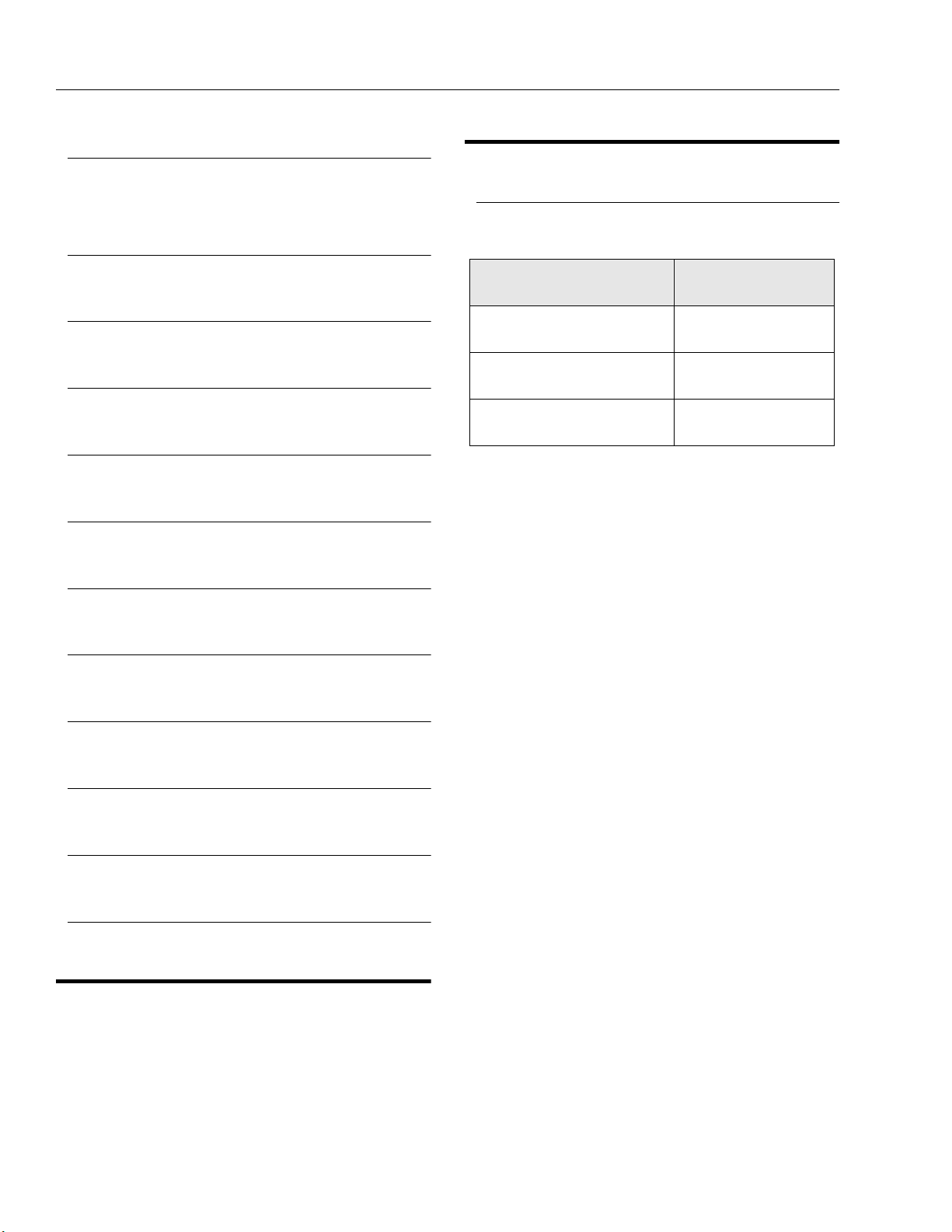
Figure 2-1. Barrel Support
Figure 2-2. Cap Screw Removal
3. If applicable, remove the cartridge-type holding
valve and fittings from the cylinder port block. Discard o-rings.
4. Place the cylinder barrel into a suitable holding fixture.
5. To aid in realignment, mark cylinder head and barrel
with a center punch. Using an allen wrench, loosen
the eight (8) cylinder head retainer cap screws and
remove cap screws from cylinder barrel.
8. W ith the barrel clamped securely, apply pressure to
the rod pulling device and carefully withdraw the
complete rod assembly from the cylinder barrel.
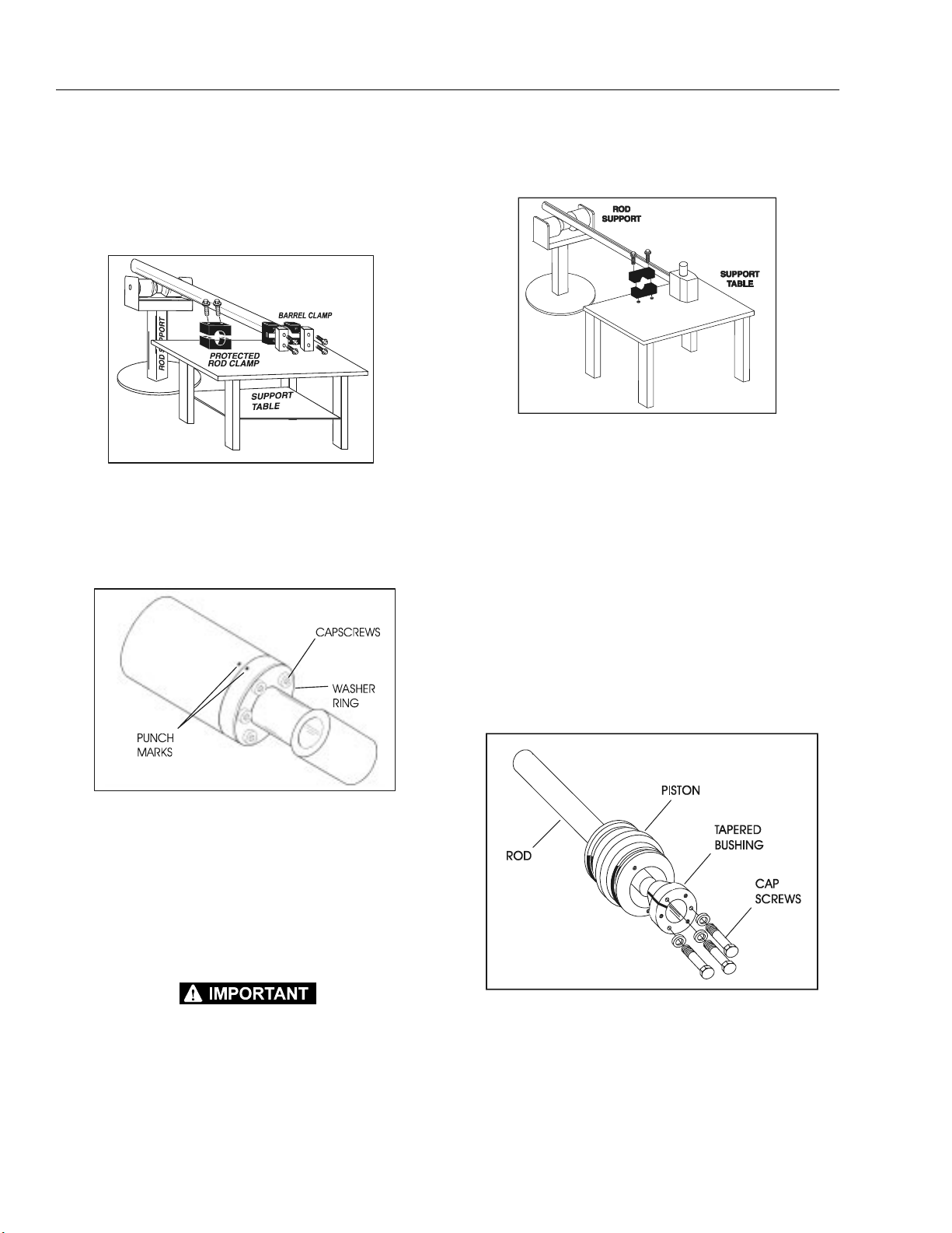
Figure 2-3. Rod Support
9. Using suitable protection, clamp the cylinder rod in
a vise or similar holding fixture as close to the piston
as possible.
10. If applicable, loosen and remove the nut which
attaches the piston to the rod, then remove the piston from the rod.
6. If applicable, using a suitable spanner wrench,
loosen the spanner nut retainer and remove the
spanner nut from the cylinder barrel.
7. Attach a suitable pulling device to the cylinder rod
port block or cylinder rod end, as applicable.
EXTREME CARE SHOULD BE TAKEN WHEN REMOVING THE
CYLINDER ROD, HEAD, A ND PISTON. AVOID PULLING TH E ROD
OFF-CENTER, WHICH COULD CAUSE DAMAGE TO THE PISTON
AND CYLINDER BARREL SURFACES.
11. If applicable, loosen and remove the cap screw(s)
securing the tapere d bushing to the piston.
12. Insert the capscrew(s) in the threaded holes in the
outer piece of the tapered bushing. Progressively
tighten the cap screw(s) until the b ushing is loose
on the piston, then remove the bushing from the piston.
Figure 2-4. Tapered Bushing Removal
13. Screw the piston counter-clockwise, by hand, and
remove the piston from the cylinder rod.
14. Remove and discard the piston o-rings, back-up
rings, guidelock rings and hydrolock seals.
2-6 – JLG Sizzor – 3120892

SECTION 2 - PROCEDURES
15. If applicable, remove th e pis t on spacer from the rod.
16. Remove the rod from the holding fixture. Remove
the cylinder head and retainer plate from the rod.
Cleaning and Inspection
1. Clean all parts thoroughly in an approved cleaning
solvent.
2. Inspect the cylinder rod for scoring, tap e rin g, ova lity,
or other damage. If necessary, dress rod with
Scotch Brite or equivalent. Replace rod if necessary.
3. Inspect threaded portion of rod for damage. Dress
threads as necessary.
4. Inspect inner surface of cylinder barrel tube for scoring or other damage. Check inside diameter for
tapering or ovality. Replace if necessary.
5. Inspect threaded portion of barrel fo r damage. Dress
threads as necessary.
6. Inspect piston surface for dama ge and scoring and
for distortion. Dress piston surface or replace piston
as necessary.
7. Inspect threaded portion of piston for damage.
dress threads as necessary.
8. Inspect seal and o-ring grooves in piston for burrs
and sharp edges. Dress applicable surfaces as necessary.
NOTE: Install the cylinder pin into the Gar-Max bearing dry.
Lubrication is not required with chrome pins and
bearings.
14. Inspect travel limiting collar or spacer for burrs and
sharp edges. If necessary, dress inside diameter
surface with Scotch Brite or equivalent.
15. If app licable, i nspect port block fitt ings and hol ding
valve. Replace as necessary.
16. Inspect the oil ports for blockage or the presence of
dirt or other foreign material. Repair as necessary.
17. If applicable, inspect piston rings for cracks or other
damage. Replace as necessary.
Assembly
NOTE: Prior to cylinder assembly, ensure that the proper
cylinder seal kit is used.
Apply a light film of hydraulic oil to all components
prior to assembly.
1. Using a special tool, pictured in the fo llowin g illustration, install a new rod seal into the applicable cylinder head gland groove. Refer to the following
illustration for the proper tool size.
9. Inspect cylinder head inside diameter for scoring or
other damage and for ovality and tapering. Replace
as necessary.
10. Inspect threaded portion of head for damage. Dress
threads as necessary.
11. Inspect seal and o-ring grooves in head for burrs
and sharp edges. Dress applicable surfaces as necessary.
12. Inspect cylinder head outside diameter for scoring
or other damage and ovality and tapering. Replace
as necessary.
13. If applicable, inspect rod and barrel bearings for
signs of correct lubrication and excessive wear. If
necessary, replace bearings as follows:
a. Thoroughly clean steel bushing hole of burrs,
dirt, etc. to facilitate bearing installation.
b. Inspect steel bushing f or w ear or o ther da mage.
If steel bushing is worn or damaged, rod or barrel (as applicable) must be replaced.
c. Lubricate inside of steel bushing with WD-40
prior to bearing installation.
d. Using arbor of the correct size, carefully press
the bearing into the steel bushing.
Figure 2-5. Rod Seal Installation
WHEN INSTALLING NEW “POLY-PAK” TYPE PISTON SEALS,
ENSURE SEALS ARE INSTALLED PROPERLY. REFER TO FIGURE
2-9., PISTON SEAL KIT FOR CORRECT SEAL ORIENTATION.
IMPROPER SEAL INSTALLATION COULD RESULT IN CYLINDER
LEAKAGE AND IMPROPER CYLINDER OPERATION.
3120892 – JLG Sizzor – 2-7
 Loading...