

Service and Maintenance Manual
Models
X17JP - X500AJ
X20JP - X600AJ
P/N - 3121623
October 21, 2013


TABLE OF CONTENTS
SECTION NO. TITLE PAGE NO.
SECTION A - INTRODUCTION - MAINTENANCE SAFETY PRECAUTIONS
A General . . . . . . . . . . . . . . . . . . . . . . . . . . . . . . . . . . . . . . . . . . . . . . . . . . . . . . . . . . . . . . . . . . . . . .A-1
B Hydraulic System Safety . . . . . . . . . . . . . . . . . . . . . . . . . . . . . . . . . . . . . . . . . . . . . . . . . . . . . . . . .A-1
C Maintenance . . . . . . . . . . . . . . . . . . . . . . . . . . . . . . . . . . . . . . . . . . . . . . . . . . . . . . . . . . . . . . . . . .A-1
SECTION 1 - SPECIFICATIONS
1.1 Capacities . . . . . . . . . . . . . . . . . . . . . . . . . . . . . . . . . . . . . . . . . . . . . . . . . . . . . . . . . . . . . . . . . . . . 1-1
1.2 Tracks . . . . . . . . . . . . . . . . . . . . . . . . . . . . . . . . . . . . . . . . . . . . . . . . . . . . . . . . . . . . . . . . . . . . . . .1-2
1.3 Power source. . . . . . . . . . . . . . . . . . . . . . . . . . . . . . . . . . . . . . . . . . . . . . . . . . . . . . . . . . . . . . . . . .1-3
HONDA ENGINE IGX440 . . . . . . . . . . . . . . . . . . . . . . . . . . . . . . . . . . . . . . . . . . . . . . . . . . . 1-4
HATZ ENGINE 1B40 . . . . . . . . . . . . . . . . . . . . . . . . . . . . . . . . . . . . . . . . . . . . . . . . . . . . . . . 1-5
PERKINS ENGINE 402D . . . . . . . . . . . . . . . . . . . . . . . . . . . . . . . . . . . . . . . . . . . . . . . . . . . . 1-5
1.4 Specifications and Performance Data. . . . . . . . . . . . . . . . . . . . . . . . . . . . . . . . . . . . . . . . . . . . . . .1-6
Dimensional Data . . . . . . . . . . . . . . . . . . . . . . . . . . . . . . . . . . . . . . . . . . . . . . . . . . . . . . . . . . . . . . 1-6
1.5 Function speeds . . . . . . . . . . . . . . . . . . . . . . . . . . . . . . . . . . . . . . . . . . . . . . . . . . . . . . . . . . . . . . .1-7
1.6 Pressure setting PSI (BAR) . . . . . . . . . . . . . . . . . . . . . . . . . . . . . . . . . . . . . . . . . . . . . . . . . . . . . . .1-8
1.7 Major components weights. . . . . . . . . . . . . . . . . . . . . . . . . . . . . . . . . . . . . . . . . . . . . . . . . . . . . . .1-9
1.8 Lubrification . . . . . . . . . . . . . . . . . . . . . . . . . . . . . . . . . . . . . . . . . . . . . . . . . . . . . . . . . . . . . . . . . . .1-10
1.9 Serial number location . . . . . . . . . . . . . . . . . . . . . . . . . . . . . . . . . . . . . . . . . . . . . . . . . . . . . . . . . .1-12
SECTION 2 - GENERAL
2.1 Machine Preparation, Inspection, and Maintenance . . . . . . . . . . . . . . . . . . . . . . . . . . . . . . . . . . .2-1
General. . . . . . . . . . . . . . . . . . . . . . . . . . . . . . . . . . . . . . . . . . . . . . . . . . . . . . . . . . . . . . . . . . 2-1
Preparation, Inspection, and Maintenance . . . . . . . . . . . . . . . . . . . . . . . . . . . . . . . . . . . . . . 2-1
Pre-Start Inspection . . . . . . . . . . . . . . . . . . . . . . . . . . . . . . . . . . . . . . . . . . . . . . . . . . . . . . . . 2-1
Pre-Delivery Inspection and Frequent Inspection . . . . . . . . . . . . . . . . . . . . . . . . . . . . . . . . . 2-1
Annual Machine Inspection . . . . . . . . . . . . . . . . . . . . . . . . . . . . . . . . . . . . . . . . . . . . . . . . . . 2-1
Preventative Maintenance . . . . . . . . . . . . . . . . . . . . . . . . . . . . . . . . . . . . . . . . . . . . . . . . . . . 2-1
2.2 Service and Guidelines . . . . . . . . . . . . . . . . . . . . . . . . . . . . . . . . . . . . . . . . . . . . . . . . . . . . . . . . . .2-2
General. . . . . . . . . . . . . . . . . . . . . . . . . . . . . . . . . . . . . . . . . . . . . . . . . . . . . . . . . . . . . . . . . . 2-2
Safety and Workmanship . . . . . . . . . . . . . . . . . . . . . . . . . . . . . . . . . . . . . . . . . . . . . . . . . . . 2-2
Cleanliness. . . . . . . . . . . . . . . . . . . . . . . . . . . . . . . . . . . . . . . . . . . . . . . . . . . . . . . . . . . . . . . 2-2
Components Removal and Installation . . . . . . . . . . . . . . . . . . . . . . . . . . . . . . . . . . . . . . . . . 2-2
Component Disassembly and Reassembly . . . . . . . . . . . . . . . . . . . . . . . . . . . . . . . . . . . . . 2-3
Pressure-Fit Parts. . . . . . . . . . . . . . . . . . . . . . . . . . . . . . . . . . . . . . . . . . . . . . . . . . . . . . . . . . 2-3
Bearings. . . . . . . . . . . . . . . . . . . . . . . . . . . . . . . . . . . . . . . . . . . . . . . . . . . . . . . . . . . . . . . . . 2-3
Gaskets . . . . . . . . . . . . . . . . . . . . . . . . . . . . . . . . . . . . . . . . . . . . . . . . . . . . . . . . . . . . . . . . . 2-3
Bolt Usage and Torque Application . . . . . . . . . . . . . . . . . . . . . . . . . . . . . . . . . . . . . . . . . . . 2-3
Hydraulic Lines and Electrical Wiring . . . . . . . . . . . . . . . . . . . . . . . . . . . . . . . . . . . . . . . . . . 2-3
Hydraulic System. . . . . . . . . . . . . . . . . . . . . . . . . . . . . . . . . . . . . . . . . . . . . . . . . . . . . . . . . . 2-3
Lubrication . . . . . . . . . . . . . . . . . . . . . . . . . . . . . . . . . . . . . . . . . . . . . . . . . . . . . . . . . . . . . . . 2-3
Battery . . . . . . . . . . . . . . . . . . . . . . . . . . . . . . . . . . . . . . . . . . . . . . . . . . . . . . . . . . . . . . . . . . 2-3
Lubrication and Servicing . . . . . . . . . . . . . . . . . . . . . . . . . . . . . . . . . . . . . . . . . . . . . . . . . . . 2-3
2.3 Lubrication and Information . . . . . . . . . . . . . . . . . . . . . . . . . . . . . . . . . . . . . . . . . . . . . . . . . . . . . .2-3
Hydraulic System. . . . . . . . . . . . . . . . . . . . . . . . . . . . . . . . . . . . . . . . . . . . . . . . . . . . . . . . . . 2-3
Hydraulic Oil . . . . . . . . . . . . . . . . . . . . . . . . . . . . . . . . . . . . . . . . . . . . . . . . . . . . . . . . . . . . . 2-4
Changing Hydraulic Oil . . . . . . . . . . . . . . . . . . . . . . . . . . . . . . . . . . . . . . . . . . . . . . . . . . . . . 2-4
Lubrication Specifications . . . . . . . . . . . . . . . . . . . . . . . . . . . . . . . . . . . . . . . . . . . . . . . . . . . 2-4
2.4 Cylinder Drift Test . . . . . . . . . . . . . . . . . . . . . . . . . . . . . . . . . . . . . . . . . . . . . . . . . . . . . . . . . . . . . .2-4
Cylinder Drift . . . . . . . . . . . . . . . . . . . . . . . . . . . . . . . . . . . . . . . . . . . . . . . . . . . . . . . . . . . . . 2-4
2.5 Pins and Composite Bearing Repair Guidelines . . . . . . . . . . . . . . . . . . . . . . . . . . . . . . . . . . . . . .2-5
2.6 Welding on JLG Equipment . . . . . . . . . . . . . . . . . . . . . . . . . . . . . . . . . . . . . . . . . . . . . . . . . . . . . .2-5
Do the Following When Welding on JLG Equipment . . . . . . . . . . . . . . . . . . . . . . . . . . . . . . 2-5
Do NOT Do the Following When Welding on JLG Equipment . . . . . . . . . . . . . . . . . . . . . . . 2-5
3121448 – JLG Lift – i

TABLE OF CONTENTS
SECTION NO. TITLE PAGE NO.
SECTION 3 - CHASSIS & TURNTABLE
3.1 RUBBER TRACK MAINTENANCE. . . . . . . . . . . . . . . . . . . . . . . . . . . . . . . . . . . . . . . . . . . . . . . . . . 3-1
Checking track tension . . . . . . . . . . . . . . . . . . . . . . . . . . . . . . . . . . . . . . . . . . . . . . . . . . . . . 3-1
Operations for loosening/tightening the track. . . . . . . . . . . . . . . . . . . . . . . . . . . . . . . . . . . . 3-1
Checking The Rubber Tracks . . . . . . . . . . . . . . . . . . . . . . . . . . . . . . . . . . . . . . . . . . . . . . . . 3-2
Replacing The Rubber Tracks. . . . . . . . . . . . . . . . . . . . . . . . . . . . . . . . . . . . . . . . . . . . . . . . 3-3
Installing the rubber track . . . . . . . . . . . . . . . . . . . . . . . . . . . . . . . . . . . . . . . . . . . . . . . . . . . 3-3
Checking tightness of nuts and bolts . . . . . . . . . . . . . . . . . . . . . . . . . . . . . . . . . . . . . . . . . . 3-4
3.2 UNDERCARRIGE COMPONENTS . . . . . . . . . . . . . . . . . . . . . . . . . . . . . . . . . . . . . . . . . . . . . . . . . 3-8
Replacement roller lower wheel and tracks adjuster . . . . . . . . . . . . . . . . . . . . . . . . . . . . . . 3-8
Replacement sprocket and gear motor . . . . . . . . . . . . . . . . . . . . . . . . . . . . . . . . . . . . . . . . 3-8
3.3 AXLE EXTENSION REMOVAL. . . . . . . . . . . . . . . . . . . . . . . . . . . . . . . . . . . . . . . . . . . . . . . . . . . . . 3-10
3.4 TRACK DRIVE - BONFIGLIOLI (2T700C2K032002) . . . . . . . . . . . . . . . . . . . . . . . . . . . . . . . . . . . .3-11
3.5 SWING DRIVE (IMO) . . . . . . . . . . . . . . . . . . . . . . . . . . . . . . . . . . . . . . . . . . . . . . . . . . . . . . . . . . . . 3-24
3.6 HONDA ENGINE IGX440 . . . . . . . . . . . . . . . . . . . . . . . . . . . . . . . . . . . . . . . . . . . . . . . . . . . . . . . .3-32
3.7 HATZ ENGINE . . . . . . . . . . . . . . . . . . . . . . . . . . . . . . . . . . . . . . . . . . . . . . . . . . . . . . . . . . . . . . . . .3-69
3.8 PERKINS ENGINE. . . . . . . . . . . . . . . . . . . . . . . . . . . . . . . . . . . . . . . . . . . . . . . . . . . . . . . . . . . . . . 3-97
3.9 ENGINE REMOVAL . . . . . . . . . . . . . . . . . . . . . . . . . . . . . . . . . . . . . . . . . . . . . . . . . . . . . . . . . . . . .3-127
3.11 CHANGING THE ELECTRIC MOTOR . . . . . . . . . . . . . . . . . . . . . . . . . . . . . . . . . . . . . . . . . . . . . . .3-128
SECTION 4 - BOOM & PLATFORM
4.1 BOOM MAINTENANCE. . . . . . . . . . . . . . . . . . . . . . . . . . . . . . . . . . . . . . . . . . . . . . . . . . . . . . . . . . 4-1
Removal of the Boom Assembly . . . . . . . . . . . . . . . . . . . . . . . . . . . . . . . . . . . . . . . . . . . . . . 4-1
Disassembly of the Main Boom. . . . . . . . . . . . . . . . . . . . . . . . . . . . . . . . . . . . . . . . . . . . . . . 4-1
Inspection . . . . . . . . . . . . . . . . . . . . . . . . . . . . . . . . . . . . . . . . . . . . . . . . . . . . . . . . . . . . . . . 4-3
Assembly of the Main Boom . . . . . . . . . . . . . . . . . . . . . . . . . . . . . . . . . . . . . . . . . . . . . . . . . 4-3
Installation of the Boom Assembly . . . . . . . . . . . . . . . . . . . . . . . . . . . . . . . . . . . . . . . . . . . . 4-4
4.2 BOOM DISASSEMBLY X20JP - X600AJ . . . . . . . . . . . . . . . . . . . . . . . . . . . . . . . . . . . . . . . . . . . . . 4-6
4.3 INSPECTION . . . . . . . . . . . . . . . . . . . . . . . . . . . . . . . . . . . . . . . . . . . . . . . . . . . . . . . . . . . . . . . . . .4-10
Checking wear and deformation of ropes and pulleys . . . . . . . . . . . . . . . . . . . . . . . . . . . . . 4-10
Assembly . . . . . . . . . . . . . . . . . . . . . . . . . . . . . . . . . . . . . . . . . . . . . . . . . . . . . . . . . . . . . . . . 4-10
Installation . . . . . . . . . . . . . . . . . . . . . . . . . . . . . . . . . . . . . . . . . . . . . . . . . . . . . . . . . . . . . . . 4-12
Three month inspection. . . . . . . . . . . . . . . . . . . . . . . . . . . . . . . . . . . . . . . . . . . . . . . . . . . . . 4-13
4.4 ROPES TENSION ADJUSTMENT PROCEDURE . . . . . . . . . . . . . . . . . . . . . . . . . . . . . . . . . . . . . . 4-13
4.5 ROTARY ACTUATOR . . . . . . . . . . . . . . . . . . . . . . . . . . . . . . . . . . . . . . . . . . . . . . . . . . . . . . . . . . .4-15
4.6 PLATFORM REMOVAL/INSTALLATION . . . . . . . . . . . . . . . . . . . . . . . . . . . . . . . . . . . . . . . . . . . . . 4-23
4.7 LOAD CELL AND FOOTSWITCH REMOVAL/INSTALLATION . . . . . . . . . . . . . . . . . . . . . . . . . . . .4-24
SECTION 5 - HYDRAULICS
5.1 CYLINDER REPAIR . . . . . . . . . . . . . . . . . . . . . . . . . . . . . . . . . . . . . . . . . . . . . . . . . . . . . . . . . . . . .5-1
5.2 REPLACEMENT HYDRAULIC PUMP . . . . . . . . . . . . . . . . . . . . . . . . . . . . . . . . . . . . . . . . . . . . . . .5-20
5.3 FUNCTION PUMP . . . . . . . . . . . . . . . . . . . . . . . . . . . . . . . . . . . . . . . . . . . . . . . . . . . . . . . . . . . . . .5-21
5.4 HYDRAULIC COMPONENT START-UP PROCEDURES AND RECOMMENDATIONS. . . . . . . . . .5-33
5.5 PRESSURE SETTING PROCEDURE . . . . . . . . . . . . . . . . . . . . . . . . . . . . . . . . . . . . . . . . . . . . . . . 5-35
SECTION 6 - JLG CONTROL SYSTEM
6.1 Introduction . . . . . . . . . . . . . . . . . . . . . . . . . . . . . . . . . . . . . . . . . . . . . . . . . . . . . . . . . . . . . . . . . . .6-1
6.2 PLATFORM/REMOTE CONTROL STATION LCD DISPLAY . . . . . . . . . . . . . . . . . . . . . . . . . . . . . .6-2
6.3 CANBUS COMMUNICATIONS . . . . . . . . . . . . . . . . . . . . . . . . . . . . . . . . . . . . . . . . . . . . . . . . . . . .6-10
Can-Bus diagnostic . . . . . . . . . . . . . . . . . . . . . . . . . . . . . . . . . . . . . . . . . . . . . . . . . . . . . . . . 6-13
Module flashing code . . . . . . . . . . . . . . . . . . . . . . . . . . . . . . . . . . . . . . . . . . . . . . . . . . . . . . 6-18
6.4 CALIBRATION REQUIREMENT. . . . . . . . . . . . . . . . . . . . . . . . . . . . . . . . . . . . . . . . . . . . . . . . . . . .6-22
6.5 PLATFORM REMOTE CONTROL SERVICE . . . . . . . . . . . . . . . . . . . . . . . . . . . . . . . . . . . . . . . . . . 6-23
6.6 MENU INPUT. . . . . . . . . . . . . . . . . . . . . . . . . . . . . . . . . . . . . . . . . . . . . . . . . . . . . . . . . . . . . . . . . .6-26
6.7 LANGUAGE . . . . . . . . . . . . . . . . . . . . . . . . . . . . . . . . . . . . . . . . . . . . . . . . . . . . . . . . . . . . . . . . . . . 6-33
6.8 MENU ERRORS. . . . . . . . . . . . . . . . . . . . . . . . . . . . . . . . . . . . . . . . . . . . . . . . . . . . . . . . . . . . . . . . 6-34
6.9 RAMPS . . . . . . . . . . . . . . . . . . . . . . . . . . . . . . . . . . . . . . . . . . . . . . . . . . . . . . . . . . . . . . . . . . . . . .6-44
ii – JLG Lift – 3121448

TABLE OF CONTENTS
SECTION NO. TITLE PAGE NO.
6.10 CURRENTS . . . . . . . . . . . . . . . . . . . . . . . . . . . . . . . . . . . . . . . . . . . . . . . . . . . . . . . . . . . . . . . . . . .6-46
6.11 WORKING HOURS . . . . . . . . . . . . . . . . . . . . . . . . . . . . . . . . . . . . . . . . . . . . . . . . . . . . . . . . . . . . . 6-49
6.12 MACHINE SETUP . . . . . . . . . . . . . . . . . . . . . . . . . . . . . . . . . . . . . . . . . . . . . . . . . . . . . . . . . . . . . .6-52
6.13 JOYSTICK . . . . . . . . . . . . . . . . . . . . . . . . . . . . . . . . . . . . . . . . . . . . . . . . . . . . . . . . . . . . . . . . . . . .6-69
6.14 CALIBRATING JOYSTICK . . . . . . . . . . . . . . . . . . . . . . . . . . . . . . . . . . . . . . . . . . . . . . . . . . . . . . . .6-70
6.15 LITHIUM SYSTEM FAULT CODES . . . . . . . . . . . . . . . . . . . . . . . . . . . . . . . . . . . . . . . . . . . . . . . . .6-71
SECTION 7 - BASIC ELECTRICAL INFORMATION & SCHEMATICS
7.1 DESCRIPTION FOR MODELS X17JP/X500AJ - X600AJ . . . . . . . . . . . . . . . . . . . . . . . . . . . . . . . .7-1
7.2 HOW TO READ THE WIRING DIAGRAMS . . . . . . . . . . . . . . . . . . . . . . . . . . . . . . . . . . . . . . . . . . .7-2
7.3 A - PHOTOCELLS - SAFETY EXCLUSION . . . . . . . . . . . . . . . . . . . . . . . . . . . . . . . . . . . . . . . . . . .7-3
7.4 B - SLEW PROXIMITY - 1° ARM SWITCH - STABILIZERS PRESSURE SENSOR . . . . . . . . . . . . .7-4
7.5 C - OUTRIGGERS SWITCHES . . . . . . . . . . . . . . . . . . . . . . . . . . . . . . . . . . . . . . . . . . . . . . . . . . . .7-5
7.6 D - CAN NETWORK - CYLINDERS POSITION SENSORS - MODEM. . . . . . . . . . . . . . . . . . . . . . .7-6
7.7 E - ROPES SWITCH - JIB POSITION SWITCH - PEDAL - LOAD CELL . . . . . . . . . . . . . . . . . . . . . 7-7
7.8 F - GROUND POSITION CONTROL BOX . . . . . . . . . . . . . . . . . . . . . . . . . . . . . . . . . . . . . . . . . . . . 7-8
7.9 G - AERIAL SAFETY LINE . . . . . . . . . . . . . . . . . . . . . . . . . . . . . . . . . . . . . . . . . . . . . . . . . . . . . . . .7-9
7.10 H - EMERGENCY DESCEND ELECTRO VALVES - WIDENING CYLINDER SENSOR
OPTIONAL . . . . . . . . . . . . . . . . . . . . . . . . . . . . . . . . . . . . . . . . . . . . . . . . . . . . . . . . . . . . . . . . . . . .7-10
7.11 I - GROUND PART: TRACKS - UNDERCARRIAGE WIDENING - 2° SPEED - PROPORTIONAL
ELECTRO VALVES . . . . . . . . . . . . . . . . . . . . . . . . . . . . . . . . . . . . . . . . . . . . . . . . . . . . . . . . . . . . .7-11
7.12 J - GROUND PART: OUTRIGGERS - ELECTRIC DIVERTER . . . . . . . . . . . . . . . . . . . . . . . . . . . . .7-12
7.13 K - AERIAL PART: BASKET LEVELLING - BASKET ROTATION - JIB - PROPORTIONAL
ELECTRO VALVE. . . . . . . . . . . . . . . . . . . . . . . . . . . . . . . . . . . . . . . . . . . . . . . . . . . . . . . . . . . . . . . 7-13
7.14 L - AERIAL PART: 1° CYLINDER - 2° CYLINDER - EXTENSION - ROTATION. . . . . . . . . . . . . . . . .7-14
7.15 M - ENGINE DIESEL VERSIONS: RPM REGULATION SYSTEM . . . . . . . . . . . . . . . . . . . . . . . . . .7-15
7.16 N - ENGINE DIESEL PERKINS 2 CYLINDERS: SENSOR AND ELECTRO STOP . . . . . . . . . . . . .7-16
7.17 O - ENGINE DIESEL PERKINS 2 CYLINDERS: START AND SPARKS. . . . . . . . . . . . . . . . . . . . . .7-17
7.18 P - ENGINE DIESEL HATZ 1 CYLINDER. . . . . . . . . . . . . . . . . . . . . . . . . . . . . . . . . . . . . . . . . . . . .7-18
7.19 Q - ENGINE GASOLINE HONDA 1 CYLINDER. . . . . . . . . . . . . . . . . . . . . . . . . . . . . . . . . . . . . . . .7-19
7.20 R - 12 VOLT POWER SUPPLY . . . . . . . . . . . . . . . . . . . . . . . . . . . . . . . . . . . . . . . . . . . . . . . . . . . .7-20
7.21 S - 120/230 VOLT LINE . . . . . . . . . . . . . . . . . . . . . . . . . . . . . . . . . . . . . . . . . . . . . . . . . . . . . . . . . .7-21
7.22 T - COMPONENTS LOCATION . . . . . . . . . . . . . . . . . . . . . . . . . . . . . . . . . . . . . . . . . . . . . . . . . . . .7-22
7.23 U - COMPONENTS ABBREVIATION MEANING . . . . . . . . . . . . . . . . . . . . . . . . . . . . . . . . . . . . . . .7-23
7.26 V - CONNECTORS LAYOUT . . . . . . . . . . . . . . . . . . . . . . . . . . . . . . . . . . . . . . . . . . . . . . . . . . . . . . 7-26
7.35 Y - LITHIUM BATTERY SYSTEM 48 VOLT X17JP - X500AJ . . . . . . . . . . . . . . . . . . . . . . . . . . . . . .7-35
7.45 Z - LITHIUM BATTERY SYSTEM 72 VOLT X20JP - X600AJ . . . . . . . . . . . . . . . . . . . . . . . . . . . . . .7-45
3121448 – JLG Lift – iii

1.1 CAPACITIES
MACHINE TYPE DRIBE HUB DRIVE CAPACITIES
X17JP
X500AJ
X20JP
X600AJ
SECTION 1 - SPECIFICATIONS
SECTION 1. SPECIFICATIONS
Table 1-1. DRIVE HUB CAPACITIES
BONFIGLIOLI
700C2K I:32 + MAG12 VP
BONFIGLIOLI
7C 00/2 2 K A A 36 G016VP30 LA
Table 1-2. HYDRAULIC & FUEL TANK CAPACITIES
AUTO
2 SPEED
2 SPEED 0,32 L (0,08 gal)
0,4 L (0.10 gal)
MACHINE
X17JP / X500AJ 10,56 gal (40 L) 1.55 gal (5.9 L) 1.3 gal (5 L)
X20JP / X600AJ 10,56 gal (40 L) 1.55 gal (5.9 L) 2.6 gal (10 L)
HYDRAULIC OIL TANK
CAPACITY
GASOLINE DIESEL
FUEL TANK
3121623 – JLG Lift – 1-1

SECTION 1 - SPECIFICATIONS
1.2 TRACKS
Machine
Model
Typ e Part Number
LOW PROFILE BLACK
COLOR
053715L0
Table 1-3. Track Specifications
Rubber Belt Track Undercar-
Dimen-
sions
riage
Drawing
Model
X17JP
X500AJ
X20JP
X600AJ
LOW PROFILE NO
MARKING
LOW PRO-
FILE BLACK
COLOR
053715LB
257215L0
Cm
180X37X
72
Cm
200X48X
66
PT9
PT10
LOW PROFILE NO
MARKING
257215LB
1-2 – JLG Lift – 3121623
MODEL
X17JP-X500AJ
X20JP-X600AJ
1.3 POWER SOURCE
SECTION 1 - SPECIFICATIONS
Table 1-4. Ground bearing pressure
PRESSURES AND REACTIONS TO THE GROUND
ON TRACKS
Maximum ground bearing
pressure
[daN/cm²] - [PSI]
0,67 daN/cm² 9,7 PSI 1731 daN 3892 lbf 2,45 daN/cm² 35.5 PSI
0,64 daN/cm² 9,2 PSI 2150 daN 4833 lbf 3,04 daN/cm² 45 PSI
Maximum ground
bearing pressure
on each pad
[daN] - [lbf]
ON OUTRIGGER
Maximum ground bearing
pressure
[daN/cm²] - [PSI]
Table 1-5. Power configuration
X17JP X20JP
Gasoline Engine Honda iGX440
15 hp (11.1 kW)
Diesel Engine Hatz 1B40
10 hp (7.46 kW)
Electric Motor 90Ah 48V Lithium-Ion 90Ah 70V Lithium-Ion
AC Electric Motor 110V 50 Hz (2,2 KW)
120V 60 Hz (1.2 kW)
230V 50 Hz (2.2 kW)
230V 60 Hz (2.2 kW)
NOTE: RPM Tolerances are ± 50.
Perkins 402.05
14 hp (10.44 Kw)
3121623 – JLG Lift – 1-3

SECTION 1 - SPECIFICATIONS
HONDA ENGINE iGX440
Table 1-6. SPECIFICATIONS HONDA ENGINE iGX440
Model iGX440U
Description code GCAWK
Type 4-stroke, overhead camshaft, single cylinder, inclined by 15°
Displacement
Bore x stroke 88.0 x 72.1 mm (3.46 x 2.84 in)
Maximum horsepower
Recommended maximum operation bhp
Maximum torque
11.2 kW (15.2 HP) / 3,600 min
8.0 kW (10.8 HP) / 3,600 min
29.8 N·m (3.0 kgf·m, 22 lbf·ft)/2,500 min
Compression ratio 8.1 : 1
Minimum fuel consumption 328 g/kW·h (241 g/HP·h, 0.53 lb/HP·h)
Ignition system CDI
Ignition timing (at no load)
10° B.T.D.C./1,400 min
13° B.T.D.C./3,600 min
Spark plug BKR7E-E (NGK), K22PR-UR (DENSO)
Lubrication system Forced splash type
Oil capacity 1.10 l (1.16 US qt, 0.97 lmp qt)
Cooling system Forced air
Starting system Recoil and starter motor
Stopping system Ignition primary circuit open
Carburetor Horizontal type batter fly valve
Air cleaner Dual element type
Governor STR (Self Tuning Regulator) governor
Fuel used Unleaded gasoline with a pump octane rating 86 or higher
438 cm
3
(26.7cu-in)
-1
-1
-1
(rpm)
-1
(rpm)
(rpm)
(rpm)
-1
(rpm)
1-4 – JLG Lift – 3121623

SECTION 1 - SPECIFICATIONS
HATZ ENGINE 1B40
Table 1-7. SPECIFICATIONS HATZ ENGINE 1B40
Typ e 1B40
Design Air-cooled four-stroke diesel engine
Combustion system Direct injection
Number of cylinders 1
Bore / stroke 88 / 76 mm
Displacement
Lubricating oil capacity without oil sump with oil
sump
Difference between “max” and “min” levels without
oil sump with oil sump
1.5
3.2
0.8
2.2
Lubricating oil consumption (after running in) 1% of fuel consumption at full load max.)
Lubricating oil pressure (oil temperature 100 °C) 2.5 bars at 3000 r.p.m. (approx.)
Direction of rotation, power take-off end anti-clockwise
Valve clearance 10 - 30 °C
Inlet and exhaust valve
Max. tilt angle in operation, in direction
Weight (incl. fuel tank, air-cleaner, exhaust silencer,
Flywheel 25° down
or automatically
55 kg approx.
recoil starter and electric starter)
Battery capacity max. 12 V / 60 Amp/h
3
462 cm
1)
l, approx.
1)
l, approx.
1)
l, approx.
1)
l, approx.
0.10 mm
2)
3)
all other directions 35°
3)
PERKINS ENGINE 402D
Table 1-8. SPECIFICATIONS PERKINS ENGINE 402D
Ty pe
Maximum Operating Speed (rpm)
Cylinders and Arrangement
Bore 67 mm (2.64 inch)
Stroke 72 mm (2.83 inch)
Displacement 0.507 L (30.939 in3)
Aspiration
Compression Ratio 23.5:1
Firing Order 1-2
Rotation that is viewed from the flywheel
Valve Lash Setting (Inlet) 0.20 mm (0.008 inch)
Valve Lash Setting (Exhaust)
Injection Indirect
402D-05 Engine
3600 rpm
In-Line two cylinder
(1)
NA
Counterclockwise
0.20 mm (0.008 inch)
3121623 – JLG Lift – 1-5

SECTION 1 - SPECIFICATIONS
1.4 SPECIFICATIONS AND PERFORMANCE DATA
Reach Specifications
Table 1-9. Reach Specifications
Max working Height
(inclusive operator)
Max Height (basket floor) 14,96 m 18,05 m 49' 06" 59' 19"
Horizontal Outreach 7 m 9.20 m 22' 95" 30' 17"
Up & Over Height 15'
Swing (non continuous) 360°
Jib - overall length 1,68 m 1,68 m 1,68 m 1,68 m
Gradeability 36,4%
Ground slope limit stabilization 12° 15° 12° 15°
Limit Approach / Depart angles
Dimensional Data
X17JP
CE
16.96 m 20.05 m NA NA
(7.80 m)
Table 1-10. SPECIFICATIONS PERKINS ENGINE 402D
X20JP
CE
18'.01"
(8.20 m)
X500AJ
ANSI
(7.80 m)
Front 20° /
Rear 20°
15'
X600AJ
ANSI
18'.01"
(8.20 m)
X17JP/
X500AJ
P la tf or m siz e (s ta nd ar d 2 p er so ns ) 0.69 m x 1.34 m
Pla t fo r m siz e (n a r ro w o ne p e rso n ) 0.62 m x 0.79 m
Stowed width (with std. 2P platform) 1,34 m
Stowed width (without platform) 0.80 m
Stowed height (on tracks) 2 m 1.99 m
Stowed length (on tracks) 4.53 m 5 m
O ut ri gg er f oo tp rin t 2.89 m x 2,88 m 2.92 m x 2.93 m
Gross machine weight:
Gasoline
Diesel
Lithium battery
1-6 – JLG Lift – 3121623
2230 Kg
2230 Kg
2300 Kg
X20JP/
X600AJ
2840 Kg
2880 Kg
2990 Kg

1.5 FUNCTION SPEEDS
SECTION 1 - SPECIFICATIONS
Table 1-11. Functions speed (in seconds)
FUNCTIONS SPEED RANGE
FUN CT IO N TIM E S ec
X 17 JP
X500AJ
TELESCOPE EXTEND 15" - 20" 21" - 28"
TELESCOPE RETRACT 16" - 22" 16" - 20"
TOWER BOOM UP 21" - 24" 30" - 35"
TOWER BOOM DOWN 19" - 22" 30" - 35"
UPPER BOOM UP 25" - 29" 35" - 40"
UPPER BOOM DOWN 24" - 30" 35" - 40"
BASKET ROTATE RIGTH 7" - 10" 7" - 10"
BASKET ROTATE LEFT 7" - 10" 7" - 10"
SWING LEFT 40" - 45" 45" - 50"
SWING RIGTH 40" - 45" 45" - 50"
JIB UP 7" - 10" 7" - 10"
JIB DOWN 7" - 10" 7" - 10"
BASKET LEVEL UP 40" - 58" 33" - 55"
BASKET LEVEL DOWN 35" - 52" 37" - 50"
DRIVE SPEED TO BE
COMPLETED
TIM E S ec
X20JP
X600AJ
TO BE
COMPLETED
Machine Orientation When Doing Speed Tests
Lift: Boom Retracted. Telescope Retracted. Lift Up,
Record Time, Lift Down, Record Time.
Swing: Machine stabilized, upper Boom at Full Elevation.
Telescope Retracted. Swing the Turntable to the end stop.
Swing the Opposite Direction, Record Time.
Te l es c o pe : Boom at Full Elevation; Telescope Retracted;
Telescope Out, Record Time. Telescope In, Record Time.
Drive: Test to be done on a smooth level surface. Drive
Select Switch should be set at 2WD High Engine. Start
approximately 25 ft. (7.62 m) from starting point so that
the unit is at maximum speed when starting the test.
Platform Rotate: Platform level and completely rotated
one direction. Rotate the opposite direction, Record Time.
Rotate the other direction, Record Time.
Articulating Jib: Platform level and centered with the
boom. Start with the Jib down. Jib Up, Record Time. Jib
Down, Record Time.
Lower Lift: Upper Boom horizontal. Telescoped In. Lower
Lift Up, Record Time. Lower Lift Down, Record Time.
TE S T N OT E S
1. Stop watch should be started with the function, not
with the controller or switch.
2. All speed tests are run from ground with remote control connected on the basket.
3. Function speeds may vary due to cold, thick hydraulic oil. Test should be run with the oil temperature
above 100° F (38° C).
3121623 – JLG Lift – 1-7

SECTION 1 - SPECIFICATIONS
1.6 PRESSURE SETTINGS - PSI (BAR)
Table 1-12. Pressure settings
UNDERCARRIAGE
Model
X14JP-X500 AJ
X20JP-X600AJ
Table 1-13. Pressure settings
Model Automatic reductions drive speed
X17JP - X500AJ
X20JP - X600AJ
Left and Right
Control Valve
Bar PSI Bar PSI
165 2393 185 2045
Bar PSI
26 380
NA NA
TOWER
Control Valve
1-8 – JLG Lift – 3121623

1.7 MAJOR COMPONENT WEIGHTS
SECTION 1 - SPECIFICATIONS
Table 1-14. Weight components
3121623 – JLG Lift – 1-9

SECTION 1 - SPECIFICATIONS
1.8 LUBRICATION
Figure 1-1.
1-10 – JLG Lift – 3121623

Table 1-15.
SECTION 1 - SPECIFICATIONS
* Readily biodegradable classification indicates one of the
following: CO2 Conversion > 60% per EPA 560/6-82-003 /
CO2 Conversion > 80% per CEC-L-33-A-93
** Virtually Non-toxic classification indicates an LC50 >
5000 per OECD 203
*** Fire Resistant classification indicates Factory Mutual
Research Corp. (FMRC) Approval
Flash point (C.O.C) for 68-46-32-22: 210°C
3121623 – JLG Lift – 1-11
SECTION 1 - SPECIFICATIONS
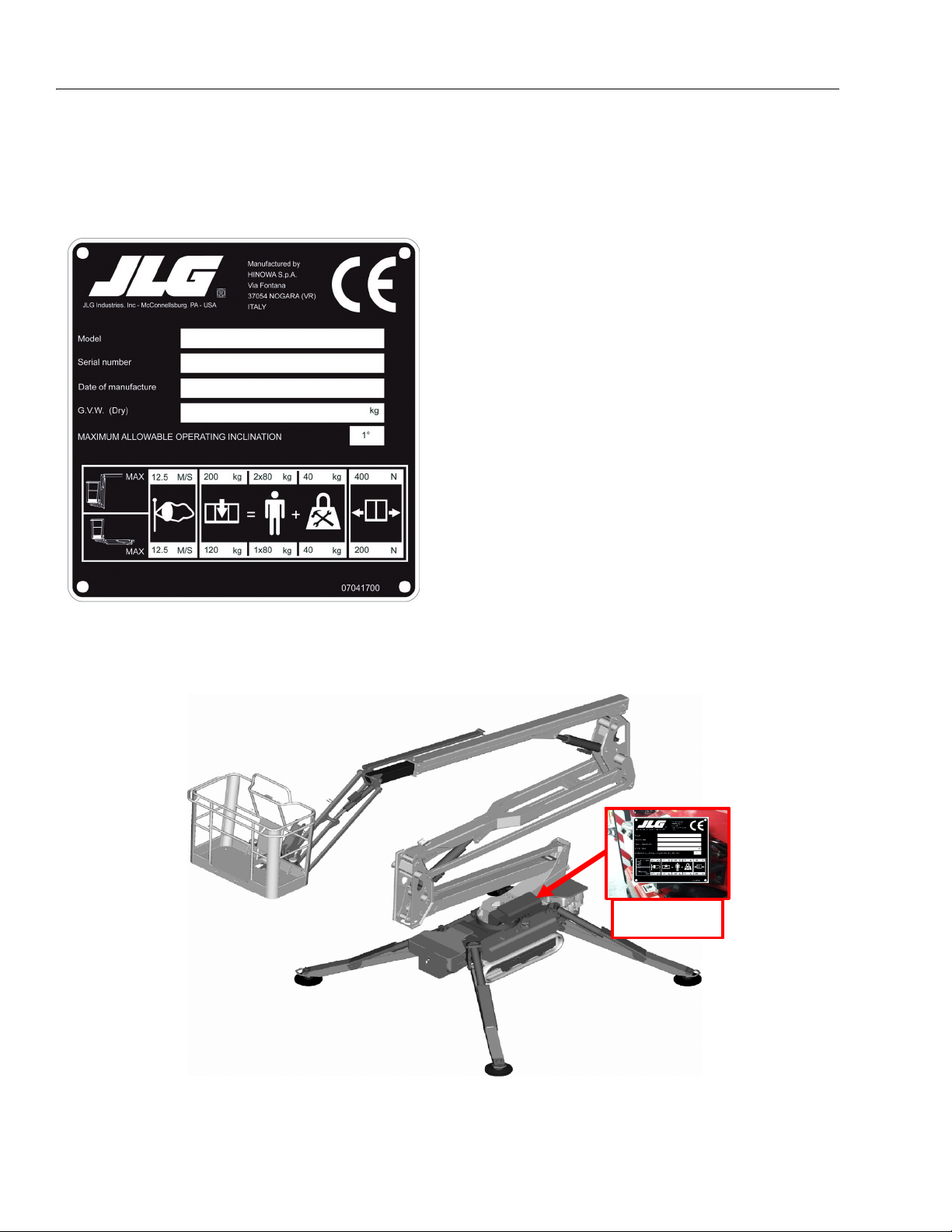
1.9 SERIAL NUMBER LOCATION
A serial number plate is affixed on to the frame a frame.
The following illustration showing the position.
Figure 1-2. Plate
SER IAL NU M BER
PLA T E L OC AT I ON
1-12 – JLG Lift – 3121623

NOTES:
SECTION 1 - SPECIFICATIONS
3121623 – JLG Lift – 1-13

SECTION 2. GENERAL
SECTION 2 - GENERAL
2.1 MACHINE PREPARATION, INSPECTION, AND MAINTENANCE
General
This section provides the necessary information needed
by those personnel that are responsible to place the
machine in operation readiness and maintain its safe
operating condition. For maximum service life and safe
operation, ensure that all the necessary inspections and
maintenance have been completed before placing the
machine into service.
Preparation, Inspection, and Maintenance
It is important to establish and conform to a comprehensive inspection and preventive maintenance program. The
following table outlines the periodic machine inspections
and maintenance recommended by JLG Industries, Inc.
Consult your national, regional, or local regulations for further requirements for aerial work platforms. The frequency
of inspections and maintenance must be increased as
environment, severity and frequency of usage requires.
Pre-Start Inspection
It is the User’s or Operator’s primary responsibility to perform a Pre-Start Inspection of the machine prior to use
daily or at each change of operator. Reference the Operator’s and Safety Manual for completion procedures for the
Pre-Start Inspection. The Operator and Safety Manual
must be read in its entirety and understood prior to performing the Pre-Start Inspection.
Pre-Delivery Inspection and Frequent Inspection
The Pre-Delivery Inspection and Frequent Inspection shall
be performed by a qualified JLG equipment mechanic.
JLG Industries, Inc. recognizes a qualified JLG equipment
mechanic as a person who, by possession of a recognized degree, certificate, extensive knowledge, training, or
experience, has successfully demonstrated the ability and
proficiency to service, repair, and maintain the subject
JLG product model.
The Pre-Delivery Inspection and Frequent Inspection procedures are performed in the same manner, but at different times. The Pre-Delivery Inspection shall be performed
prior to each sale, lease, or rental delivery. The Frequent
Inspection shall be accomplished for each machine in service for 3 months or 150 hours (whichever comes first);
out of service for a period of more than 3 months; or when
purchased used. The frequency of this inspection must be
increased as environment, severity and frequency of
usage requires.
Reference the JLG Pre-Delivery and Frequent Inspection
Form and the Inspection and Preventative Maintenance
Schedule for items requiring inspection during the performance of these inspections. Reference the appropriate
areas of this manual for servicing and maintenance procedures.
Annual Machine Inspection
The Annual Machine Inspection must be performed by a
Factory-Certified Service Technician on an annual basis,
no later than thirteen (13) months from the date of the
prior Annual Machine Inspection. JLG Industries, Inc. recognizes a Factory-Certified Service Technician as a person who has successfully completed the JLG Service
Training School for the subject JLG product model. Reference the machine Service and Maintenance Manual and
appropriate JLG inspection form for performance of this
inspection.
Reference the JLG Annual Machine Inspection Form and
the Inspection and Preventative Maintenance Schedule for
items requiring inspection during the performance of this
inspection. Reference the appropriate areas of this manual for servicing and maintenance procedures.
For the purpose of receiving safety-related bulletins, it is
important that JLG Industries, Inc. has updated ownership
information for each machine. When performing each
Annual Machine Inspection, notify JLG Industries, Inc. of
the current machine ownership.
Preventative Maintenance
In conjunction with the specified inspections, maintenance shall be performed by a qualified JLG equipment
mechanic. JLG Industries, Inc. recognizes a qualified JLG
equipment mechanic as a person who, by possession of a
recognized degree, certificate, extensive knowledge, training, or experience, has successfully demonstrated the
ability and proficiency to service, repair, and maintain the
subject JLG product model.
Reference the Preventative Maintenance Schedule and
the appropriate areas of this manual for servicing and
maintenance procedures. The frequency of service and
maintenance must be increased as environment, severity
and frequency of usage requires.
3121623 – JLG Lift – 2-1

SECTION 2 - GENERAL
Table 2-1. Inspection and Maintenance
Type Frequency
Pre-Start
Inspection
Pre-Delivery
Inspection
Frequent
Inspection
Annual Machine
Inspection
Preventative
Maintenance
Prior to use each day; or
At each Operator change.
Prior to each sale, lease, or
rental delivery.
In service for 3 months or 150 hours,
whichever comes first; or
Out of service for a period of more than
3 months; or
Purchased used.
Annually, no later than 13 months from
the date of the prior inspection.
At intervals as specified in the Service
and Maintenance Manual.
2.2 SERVICE AND GUIDELINES
General
The following information is provided to assist you in the
use and application of servicing and maintenance procedures contained in this book.
Safety and Workmanship
Your safety, and that of others, is the first consideration
when engaging in the maintenance of equipment. Always
be conscious of weight. Never attempt to move heavy
parts without the aid of a mechanical device. Do not allow
heavy objects to rest in an unstable position. When raising
a portion of the equipment, ensure that adequate support
is provided.
Cleanliness
1. The most important single item in preserving the
long service life of a machine is to keep dirt and foreign materials out of the vital components. Precautions have been taken to safeguard against this.
Shields, covers, seals, and filters are provided to
keep air, fuel, and oil supplies clean; however, these
items must be maintained on a scheduled basis in
order to function properly.
Primary
Responsibility
User or Operator User or Operator Operator and Safety Man-
Owner, Dealer, or
User
Owner, Dealer, or
User
Owner, Dealer, or
User
Owner, Dealer, or
User
2. At any time when air, fuel, or oil lines are disconnected, clear adjacent areas as well as the openings
and fittings themselves. As soon as a line or component is disconnected, cap or cover all openings to
prevent entry of foreign matter.
3. Clean and inspect all parts during servicing or maintenance, and assure that all passages and openings
are unobstructed. Cover all parts to keep them
clean. Be sure all parts are clean before they are
installed. New parts should remain in their containers until they are ready to be used.
Service
Qualification
Qualified JLG
Mechanic
Qualified JLG
Mechanic
Factory-Certified
Service Techni-
cian
Qualified JLG
Mechanic
Reference
ual
Service and Maintenance
Manual and applicable JLG
inspection form.
Service and Maintenance
Manual and applicable JLG
inspection form.
Service and Maintenance
Manual and applicable JLG
inspection form.
Service and Maintenance
Manual
Components Removal and Installation
1. Use adjustable lifting devices, whenever possible, if
mechanical assistance is required. All slings (chains,
cables, etc.) should be parallel to each other and as
near perpendicular as possible to top of part being
lifted.
2. Should it be necessary to remove a component on
an angle, keep in mind that the capacity of an eyebolt or similar bracket lessens, as the angle between
the supporting structure and the component
becomes less than 90 degrees.
3. If a part resists removal, check to see whether all
nuts, bolts, cables, brackets, wiring, etc., have been
removed and that no adjacent parts are interfering.
2-2 – JLG Lift – 3121623

SECTION 2 - GENERAL
Component Disassembly and Reassembly
When disassembling or reassembling a component, complete the procedural steps in sequence. Do not partially
disassemble or assemble one part, then start on another.
Always recheck your work to assure that nothing has been
overlooked. Do not make any adjustments, other than
those recommended, without obtaining proper approval.
Pressure-Fit Parts
When assembling pressure-fit parts, use an anti-seize or
molybdenum disulfide base compound to lubricate the
mating surface.
Bearings
1. When a bearing is removed, cover it to keep out dirt
and abrasives. Clean bearings in nonflammable
cleaning solvent and allow to drip dry. Compressed
air can be used but do not spin the bearing.
2. Discard bearings if the races and balls (or rollers)
are pitted, scored, or burned.
3. If bearing is found to be serviceable, apply a light
coat of oil and wrap it in clean (waxed) paper. Do not
unwrap reusable or new bearings until they are
ready to install.
4. Lubricate new or used serviceable bearings before
installation. When pressing a bearing into a retainer
or bore, apply pressure to the outer race. If the bearing is to be installed on a shaft, apply pressure to the
inner race.
Hydraulic Lines and Electrical Wiring
Clearly mark or tag hydraulic lines and electrical wiring, as
well as their receptacles, when disconnecting or removing
them from the unit. This will assure that they are correctly
reinstalled.
Hydraulic System
1. Keep the system clean. If evidence of metal or rubber particles are found in the hydraulic system, drain
and flush the entire system.
2. Disassemble and reassemble parts on clean work
surface. Clean all metal parts with non-flammable
cleaning solvent. Lubricate components, as
required, to aid assembly.
Lubrication
Service applicable components with the amount, type,
and grade of lubricant recommended in this manual, at
the specified intervals. When recommended lubricants are
not available, consult your local supplier for an equivalent
that meets or exceeds the specifications listed.
Battery
Clean battery, using a non-metallic brush and a solution of
baking soda and water. Rinse with clean water. After
cleaning, thoroughly dry battery and coat terminals with
an anti corrosion compound.
Lubrication and Servicing
Components and assemblies requiring lubrication and
servicing are shown in the Lubrication Chart in Section 1.
Gaskets
Check that holes in gaskets align with openings in the
mating parts. If it becomes necessary to hand-fabricate a
gasket, use gasket material or stock of equivalent material
and thickness. Be sure to cut holes in the right location, as
blank gaskets can cause serious system damage.
Bolt Usage and Torque Application
1. Use bolts of proper length. A bolt which is too long
will bottom before the head is tight against its related
part. If a bolt is too short, there will not be enough
thread area to engage and hold the part properly.
When replacing bolts, use only those having the
same specifications of the original, or one which is
equivalent.
2. Unless specific torque requirements are given within
the text, standard torque values should be used on
heat-treated bolts, studs, and steel nuts, in accordance with recommended shop practices. (See
Torque Chart Section 1.)
3121623 – JLG Lift – 2-3
2.3 LUBRICATION AND INFORMATION
Hydraulic System
1. The primary enemy of a hydraulic system is contamination. Contaminants enter the system by various
means, e.g., using inadequate hydraulic oil, allowing
moisture, grease, filings, sealing components, sand,
etc., to enter when performing maintenance, or by
permitting the pump to cavitate due to insufficient
system warm-up or leaks in the pump supply (suction) lines.
2. The design and manufacturing tolerances of the
component working parts are very close, therefore,
even the smallest amount of dirt or foreign matter
entering a system can cause wear or damage to the
components and generally results in faulty operation. Every precaution must be taken to keep
hydraulic oil clean, including reserve oil in storage.
Hydraulic system filters should be checked,
cleaned, and/or replaced as necessary, at the speci-

SECTION 2 - GENERAL
fied intervals required in the Lubrication Chart in
Section 1. Always examine filters for evidence of
metal particles.
3. Cloudy oils indicate a high moisture content which
permits organic growth, resulting in oxidation or corrosion. If this condition occurs, the system must be
drained, flushed, and refilled with clean oil.
4. It is not advisable to mix oils of different brands or
types, as they may not contain the same required
additives or be of comparable viscosities. Good
grade mineral oils, with viscosities suited to the
ambient temperatures in which the machine is operating, are recommended for use.
NOTE: Metal particles may appear in the oil or filters of new
machines due to the wear-in of meshing components.
Hydraulic Oil
Refer to Section 1 for recommendations for viscosity
ranges.
Changing Hydraulic Oil
1. Filter elements must be changed after the first 50
hours of operation and every 300 hours (unless
specified otherwise) thereafter. If it is necessary to
change the oil, use only those oils meeting or
exceeding the specifications appearing in this manual. If unable to obtain the same type of oil supplied
with the machine, consult local supplier for assistance in selecting the proper equivalent. Avoid mixing petroleum and synthetic base oils. JLG
Industries recommends changing the hydraulic oil
annually.
2. Use every precaution to keep the hydraulic oil clean.
If the oil must be poured from the original container
into another, be sure to clean all possible contaminants from the service container. Always clean the
mesh element of the filter and replace the cartridge
any time the system oil is changed.
Lubrication Specifications
Specified lubricants, as recommended by the component
manufacturers, are always the best choice, however,
multi-purpose greases usually have the qualities which
meet a variety of single purpose grease requirements.
Should any question arise, regarding the use of greases in
maintenance stock, consult your local supplier for evaluation. Refer to Section 1 for an explanation of the lubricant
key designations appearing in the Lubrication Chart.
2.4 CYLINDER DRIFT TEST
Maximum acceptable cylinder drift is to be measured
using the following methods.
Cylinder Drift
Table 2-2. Cylinder Drift
CYLINDER BORE
DIAMETER
inches mm inches mm
2,17 55 0.020 0.53
2.36 60 0.021 0.54
2,56 65 0.029 0.74
2,95 75 0.013 0.35
3,15 80 0.011 0.29
3,94 100 0.007 0.20
4.52 115 0.005 0.15
Drift is to be measured at the cylinder rod with a calibrated
dial indicator. The cylinder oil must be at ambient temperature and temperature stabilized.
The cylinder must have the normal load, which is the normal platform load applied.
If the cylinder passes this test, it is acceptable.
MAX ACCEPTABLE DRIF
IN 1 MINUTES
3. While the unit is shut down, a good preventive main-
tenance measure is to make a thorough inspection
of all hydraulic components, lines, fittings, etc., as
well as a functional check of each system, before
placing the machine back in service.
2-4 – JLG Lift – 3121623

SECTION 2 - GENERAL
2.5 PINS AND COMPOSITE BEARING REPAIR GUIDELINES
Filament wound bearings.
1. Pinned joints should be disassembled and
inspected if the following occurs:
a. Excessive sloppiness in joints.
b. Noise originating from the joint during operation.
2. Filament wound bearings should be replaced if any
of the following is observed:
a. Frayed or separated fibers on the liner surface.
b. Cracked or damaged liner backing.
c. Bearings that have moved or spun in their hous-
ing.
d. Debris embedded in liner surface.
3. Pins should be replaced if any of the following is
observed (pin should be properly cleaned prior to
inspection):
a. Detectable wear in the bearing area.
b. Flaking, pealing, scoring, or scratches on the pin
surface.
c. Rusting of the pin in the bearing area.
2.6 WELDING ON JLG EQUIPMENT
NOTE: This instruction applies to repairs, or modifications to the
machine and to welding performed from the machine on
an external structure, or component,
Do the Following When Welding on JLG Equipment
• Disconnect the battery.
• Disconnect the moment pin connection (where fitted)
• Ground only to structure being welded.
Do NOT Do the Following When Welding on JLG Equipment
• Ground on frame and weld on any other area than the
chassis.
• Ground on turntable and weld on any other area than
the turntable.
• Ground on the platform/support and weld on any other
area than the platform/support.
• Ground on a specific boom section and weld on any
other area than that specific boom section.
• Allow pins, wear pads, wire ropes, bearings, gearing,
seals, valves, electrical wiring, or hoses to be between
the grounding position and the welded area.
4. Re-assembly of pinned joints using filament wound
bearings.
a. Housing should be blown out to remove all dirt
and debris...bearings and bearing housings
must be free of all contamination.
b. Bearing / pins should be cleaned with a solvent
to remove all grease and oil...filament wound
bearing are a dry joint and should not be lubricated unless otherwise instructed (i.e. sheave
pins).
c. Pins should be inspected to ensure it is free of
burrs, nicks, and scratches which would damage the bearing during installation and operation.
FAILURE TO COMPLY WITH THE ABOVE REQUIREMENTS MAY
RESULT IN COMPONENT DAMAGE (I.E. ELECTRONIC MODULES,
SWING BEARING, COLLECTOR RING, BOOM WIRE ROPES ETC.)
3121623 – JLG Lift – 2-5

SECTION 2 - GENERAL
NOTES:
2-6 – JLG Lift – 3121623

SECTION 3 - CHASSIS & TURNTABLE
A
SECTION 3. CHASSIS & TURNTABLE
3.1 RUBBER TRACK MAINTENANCE
Checking track tension
Stop the machine on firm, level surface. Lift the machine into
safe conditions and place stable supports under the undercarriage frame for total support. Parallel with the central
roller of the under-carriage, measure distance (A) from the
bottom of the roller to the rigid inside of the rubber belt.
Track tension is normal if measurement (A) is between 10
and 15 mm.
If track tension is not within the measurements specified
above, loose or too taught, follow the procedures illustrated
in the paragraph below.
Figure 3-1.
4. When correct track tension has been obtained, turn
valve (1) in a clockwise direction and tighten it.
Clean all traces of grease.
Figure 3-2.
5. To tighten the track, connect a grease gun to
greaser (2) and add grease until belt tension is
within the specified values.
Operations for loosening/tightening the track
The grease contained in the hydraulic track is pressurised.
For this reason, do not loosen the greasing valve (1) by
more than 1 turn; if the valve is loosened too much, it risks
being expelled under the effect of the pressure of the
grease, putting the safety of the operator at risk. Never
loosen greaser (2).
When gravel or mud are blocked between the toothed wheel
and the track links, remove it before loosening.
1. Remove the screws and take of adjustment access
lid 3.
2. To loosen the track, slowly unscrew valve 1 in an
anti-clockwise direction for no more than one turn.
One turn of valve 1 is sufficient to loosen the track.
3. If the grease does not start to drain, turn the track
slowly.
IT IS NOT NORMAL IF THE TRACK REMAINS
TAUGHT AFTER HAVING TURNED VALVE (1) IN AN
ANTI-CLOCKWISE DIRECTION OR IF THE TRACK IS
STILL LOOSE AFTER HAVING PUT GREASE INTO
GREASER (2). NEVER TRY TO REMOVE THE TRACKS
OR DISASSEMBLE THE TRACK-TENSIONED CYLINDER BECAUSE THE GREASE PRESSURE INSIDE THE
TRACK IS VERY DANGEROUS.
3121623 – JLG Lift – 3-1

SECTION 3 - CHASSIS & TURNTABLE
PATTERN
WHEEL SIDE
SPROCKET
HOLE
METAL CORE
STEEL WIRE
g
WORN PARTS
CRACK
Checking The Rubber Tracks
Figure 3-3. Rubber Track Structure
The structure of the rubber track is illustrated in Figure 3-3.
The steel ropes and the metal core are imbedded into the
rubber. The carved profiles are used to give traction when
moving over loose land. They are situated in the lower part
resting on the ground, while the wheel guides situated inside
the track, prevent the track from escaping from the guide
rollers.
CAUSES OF DAMAGE
1. Breakage of the steel ropes
Excessive tension causes the steel ropes to break in
the following conditions:
a. when stones or foreign bodies accumulate
between the track and the under-carriage
frame;
b. when the track escapes from its guide;
c. in the case of strong friction such as rapid
direction changes.
2. Wear and breakage of the metal cores
As for breakage of the steel ropes, stated above,
excessive tension may cause the metal cores to
bend or break, as may the following causes:
a. incorrect contact between toothed wheel and
track;
b. breakage of internal rollers;
c. functioning on sandy land.
3. Separation of the metal cores
Figure 3-4.
a. The metal core acts as a type of adhesive of
the rubber between the core itself and the
steel ropes. Separation may be caused by
excessive tension as breakage of the ropes
for the following reasons:
b. The metal cores have been wound by the
worn toothed wheel as indicated in the figure.
When this wear and abrasion is detected, the
toothed wheel must be replaced as soon as
possible.
c. If it breaks, as stated in item 2, "Wear and
breakage of the metal cores", the track must
be replaced because this damage leads to a
complete loss of functions.
4. Abrasion and fatigue cracks
a. The cracks at the base of the carved profile
occur due to bending fatigue of the rubber
caused by the toothed wheel and the tracktensioning wheel.
b. The cracks and bends on the edge of the rub-
ber are due to manoeuvres with the track in
presence of cement kerbs and edges.
Figure 3-5.
c. The cracks and abrasions in the rubber on the
tracks of the roller guide originate from fatigue
from the compression of the rubber by the
weight of the wheel, together with functioning
on sandy land, or repeated and abrupt
changes of direction.
d. Abrasion of the carved profiles may occur
especially if slewing on concrete surfaces or
on gravel or hard surfaces are carried out.
e. The damage indicated in paragraphs a, b,
and c above, must not be considered fatal for
the track and, even if in presence of gradual
3-2 – JLG Lift – 3121623

SECTION 3 - CHASSIS & TURNTABLE
4
5
6
5
20
2
0
2
B
H
1
9
and progressive damage, they allow the track
to continue working. The development of the
damage indicated in point 3 leads to the
exposure of the metal cores and if they are
exposed for more than half of the track circumference, it means that it is time to replace
them. It can however still be used.
5. Cracks due to external factors
Cracks on external track surfaces (those in contact
with the ground) are often due to contact with
gravel, sharp stones, sharp materials, nails, glass,
which cause cuts. From the rubber properties point
of view, this is inevitable although it does depend on
service conditions. Cracks on the internal surface of
the circumference and on the edge of the rubber
originate from contact of the belt with the structure
of the undercarriage or with sharp concrete edges.
The increase in cracks is relatively small. Even if it
does not appear to be in good condition the track
can be used in heavy duty conditions.
Replacing The Rubber Tracks
THE GREASE CONTAINED IN THE HYDRAULIC
TRACK IS PRESSURISED. FOR THIS REASON, DO NOT
LOOSEN THE GREASING VALVE (1) BY MORE THAN 1
TURN; IF THE VALVE IS LOOSENED TOO MUCH, IT
RISKS BEING EXPELLED UNDER THE EFFECT OF
THE PRESSURE OF THE GREASE, PUTTING THE
SAFETY OF THE OPERATOR AT RISK. NEVER
LOOSEN GREASER (2).
4. If the grease does not start to drain, turn the track
slowly.
5. Insert three steel pipes (4) inside the track in the
space between the rollers. Turn the driving wheel
backwards (5) in a way that the steel pipes proceed
with the track and engage on the track-tensioning
wheel. Apply force (6) laterally to allow the track to
run and lift it from the track-tensioning wheel.
Figure 3-7.
Installing The Rubber Track
ENSURE SAFE CONDITIONS WITH THE MACHINE
LIFTED TO PROCEED WITH MOUNTING THE
TRACKS.
When gravel or mud are blocked between the toothed wheel
and the track links, remove it before loosening.
Removing The Rubber Track
1. Check that the grease contained in the hydraulic cyl-
inder has been removed.
2. Engage the track links with the toothed wheel and
1. Stop the machine on solid, level land, lift it and sup-
port it in safe conditions, using the outriggers.
position the other end of the track on the track-tensioning wheel.
3. Turn the driving wheel in reverse (7) pushing the
track plate inside the frame (8).
4. Position the track using a steel pipe and turn the
driving wheel again.
5. Ensure that the track links are correctly engaged in
the toothed wheel and in the track-tensioning wheel.
Figure 3-6.
2. Remove the screws and take of adjustment access
6. Adjust track tension (see paragraph -Operations for
loosening/tightening the track).
7. Rest the tracked under-carriage on the ground.
lid 3.
3. To loosen the track, slowly unscrew valve 1 in an
anti-clockwise direction for no more than one turn.
One turn of valve 1 is sufficient to loosen the track.
3121623 – JLG Lift – 3-3

SECTION 3 - CHASSIS & TURNTABLE
8
7
52
0
20
2
B
H1
9
Figure 3-8.
Checking tightness of nuts and bolts
Depending on the use of the platform, it is indispensable to
check the parts and the nuts and bolts in general, which are
subject to loosening.
Pay particular attention to the frame components, such as
track-tensioning wheels, traversing geared motors, driving
wheels and guide rollers. Check that they are tightened sufficiently as indicated in the following table.
The values indicated are to be applied unless otherwise
stated in this manual.
3-4 – JLG Lift – 3121623

Size TPI Bolt Dia
Tensile
Stress Area
Clamp Load
See Note 4
Clamp Load
See Note 4
In Sq In LB IN-LB [N.m] IN-LB [N.m] IN-LB [N.m] LB IN-LB [N.m] IN-LB [N.m] IN-LB [N.m]
4 40 0,1120 0,00604
48 0,1120 0,00661
6 32 0,1380 0,00909
40 0,1380 0,01015
8 32 0,1640 0,01400
36 0,1640 0,01474
10 24 0,1900 0,01750
32 0,1900 0,02000
1/4 20 0,2500 0,0318 2860 122 14 114 13 2860 143 16 129 15
28 0,2500 0,0364 3280 139 16 131 15 3280 164 19 148 17
In Sq In LB FT-LB [N.m] FT-LB [N.m] FT-LB [N.m] LB FT-LB [N.m] FT-LB [N.m] FT-LB [N.m]
5/16 18 0,3125 0,0524 4720 20 25 20 25 20 25 4720 25 35 20 25 20 25
24 0,3125 0,0580 5220 25 35 20 25 20 25 5220 25 35 25 35 20 25
3/8 16 0,3750 0,0775 7000 35 50 35 50 35 50 7000 45 60 40 55 35 50
24 0,3750 0,0878 7900 40 55 40 55 35 50 7900 50 70 45 60 35 50
7/16 14 0,4375 0,1063 9550 60 80 55 75 50 70 9550 70 95 65 90 50 70
20 0,4375 0,1187 10700 65 90 60 80 60 80 10700 80 110 70 95 60 80
1/2 13 0,5000 0,1419 12750 90 120 85 115 80 110 12750 105 145 95 130 80 110
20 0,5000 0,1599 14400 100 135 95 130 90 120 14400 120 165 110 150 90 120
9/16 12 0,5625 0,1820 16400 130 175 125 170 115 155 16400 155 210 140 190 115 155
18 0,5625 0,2030 18250 145 195 135 185 130 175 18250 170 230 155 210 130 175
5/8 11 0,6250 0,2260 20350 180 245 170 230 160 220 20350 210 285 190 260 160 220
18 0,6250 0,2560 23000 205 280 190 260 180 245 23000 240 325 215 290 180 245
3/4 10 0,7500 0,3340 30100 320 435 300 280 380 30100 375 510 340 460 280 380
16 0,7500 0,3730 33600 355 485 335 455 315 430 33600 420 570 380 515 315 430
7/8 9 0,8750 0,4620 41600 515 700 485 660 455 620 41600 605 825 545 740 455 620
14 0,8750 0,5090 45800 570 775 535 730 500 680 45800 670 910 600 815 500 680
1 8 1,0000 0,6060 51500 730 995 685 930 645 875 51500 860 1170 775 1055 645 875
12 1,0000 0,6630 59700 845 1150 795 1080 745 1015 59700 995 1355 895 1215 745 1015
1 1/8 7 1,1250 0,7630 68700 1095 1490 1030 1400 965 1310 68700 1290 1755 1160 1580 965 1310
12 1,1250 0,8560 77000 1225 1665 1155 1570 1085 1475 77000 1445 1965 1300 1770 1085 1475
1 1/4 7 1,2500 0,9690 87200 1545 2100 1455 1980 1365 1855 87200 1815 2470 1635 2225 1365 1855
12 1,2500 1,0730 96600 1710 2325 1610 2190 1510 2055 96600 2015 2740 1810 2460 1510 2055
1 3/8 6 1,3750 1,1550 104000 2025 2755 1905 2590 1785 2430 104000 2385 3245 2145 2915 1785 2430
12 1,3750 1,3150 118100 2300 3130 2165 2945 2030 2760 118100 2705 3680 2435 3310 2030 2760
1 1/2 6 1,5000 1,4050 126500 2690 3660 2530 3440 2370 3225 126500 3165 4305 2845 3870 2370 3225
12 1,5000 1,5800 142200 3020 4105 2845 3870 2665 3625 142200 3555 4835 3200 4350 2665 3625
4. CLAMP LOAD LISTED FOR SHCS IS SAME AS GRADE 8 OR CLASS 10.9 AND DOES NOT REPRESENT FULL STRENGTH CAPABILITY OF SHCS. IF HIGHER LOAD IS REQUIRED, ADDITIONAL TESTING IS REQUIRED.
SOCKET HEAD CAP SCREWS
Torque
(Dry)
K = .20
Torque
(Loctite® 242
TM
or 271
TM
OR Vibra-TITE
TM
111 or
140 OR Precoat 85®
K=0.18
Torque
(Loctite® 262
TM
or Vibra-
TITE
TM
131) K=0.15
Zinc Yellow Chromate Fasteners (Ref 4150707)*Magni Coating (Ref 4150701)*
Torque
(Dry) K = .17
Torque
(Loctite® 242
TM
or 271
TM
OR Vibra-TITE
TM
111 or
140 OR Precoat 85®
K=0.16
Torque
(Loctite® 262
TM
or Vibra-
TITE
TM
131) K=0.15
2. ALL TORQUE VALUES ARE STATIC TORQUE MEASURED PER STANDARD AUDIT METHODS TOLERANCE = ±10%
NOTES: 1. THESE TORQUE VALUES DO NOT APPLY TO CADMIUM PLATED FASTENERS
*3. ASSEMBLY USES HARDENED WASHER OR FASTENER IS PLACED AGAINST PLATED STEEL OR RAW ALUMINUM
SECTION 3 - CHASSIS & TURNTABLE
Figure 3-9.
3121623 – JLG Lift – 3-5

SECTION 3 - CHASSIS & TURNTABLE
Size TPI Bolt Dia
Tensile
Stress Area
Clamp Load Clamp Load
In Sq In LB IN-LB [N.m] IN-LB [N.m] IN-LB [N.m] IN-LB [N.m] LB IN-LB [N.m] IN-LB [N.m] IN-LB [N.m]
4 40 0,1120 0,00604 380 8 0,9 6 0,7
48 0,1120 0,00661 420 9 1,0 7 0,8
6 32 0,1380 0,00909 580 16 1,8 12 1,4
40 0,1380 0,01015 610 18 2,0 13 1,5
8 32 0,1640 0,01400 900 30 3,4 22 2,5
36 0,1640 0,01474 940 31 3,5 23 2,6 1320 43 5
10 24 0,1900 0,01750 1120 43 4,8 32 3,5 1580 60 7
32 0,1900 0,02000 1285 49 5,5 36 4 1800 68 8
1/4 20 0,2500 0,0318 2020 96 10,8 75 9 105 12 2860 143 16 129 15
28 0,2500 0,0364 2320 120 13,5 86 10 135 15 3280 164 19 148 17
In Sq In LB FT-LB [N.m] FT-LB [N.m] FT-LB [N.m] FT-LB [N.m] LB FT-LB [N.m] FT-LB [N.m] FT-LB [N.m]
5/16 18 0,3125 0,0524 3340 17 23 13 18 19 26 16 22 4720 25 35 20 25 20 25
24 0,3125 0,0580 3700 19 26 14 19 21 29 17 23 5220 25 35 25 35 20 25
3/8 16 0,3750 0,0775 4940 30 41 23 31 35 48 28 38 7000 45 60 40 55 35 50
24 0,3750 0,0878 5600 35 47 25 34 40 54 32 43 7900 50 70 45 60 35 50
7/16 14 0,4375 0,1063 6800 50 68 35 47 55 75 45 61 9550 70 95 65 90 50 70
20 0,4375 0,1187 7550 55 75 40 54 60 82 50 68 10700 80 110 70 95 60 80
1/2 13 0,5000 0,1419 9050 75 102 55 75 85 116 68 92 12750 105 145 95 130 80 110
20 0,5000 0,1599 10700 90 122 65 88 100 136 80 108 14400 120 165 110 150 90 120
9/16 12 0,5625 0,1820 11600 110 149 80 108 120 163 98 133 16400 155 210 140 190 115 155
18 0,5625 0,2030 12950 120 163 90 122 135 184 109 148 18250 170 230 155 210 130 175
5/8 11 0,6250 0,2260 14400 150 203 110 149 165 224 135 183 20350 210 285 190 260 160 220
18 0,6250 0,2560 16300 170 230 130 176 190 258 153 207 23000 240 325 215 290 180 245
3/4 10 0,7500 0,3340 21300 260 353 200 285 388 240 325 30100 375 510 340 460 280 380
16 0,7500 0,3730 23800 300 407 220 298 330 449 268 363 33600 420 570 380 515 315 430
7/8 9 0,8750 0,4620 29400 430 583 320 434 475 646 386 523 41600 605 825 545 740 455 620
14 0,8750 0,5090 32400 470 637 350 475 520 707 425 576 45800 670 910 600 815 500 680
1 8 1,0000 0,6060 38600 640 868 480 651 675 918 579 785 51500 860 1170 770 1045 645 875
12 1,0000 0,6630 42200 700 949 530 719 735 1000 633 858 59700 995 1355 895 1215 745 1015
1 1/8 7 1,1250 0,7630 42300 800 1085 600 813 840 1142 714 968 68700 1290 1755 1160 1580 965 1310
12 1,1250 0,8560 47500 880 1193 660 895 925 1258 802 1087 77000 1445 1965 1300 1770 1085 1475
1 1/4 7 1,2500 0,9690 53800 1120 1518 840 1139 1175 1598 1009 1368 87200 1815 2470 1635 2225 1365 1855
12 1,2500 1,0730 59600 1240 1681 920 1247 1300 1768 1118 1516 96600 2015 2740 1810 2460 1510 2055
1 3/8 6 1,3750 1,1550 64100 1460 1979 1100 1491 1525 2074 1322 1792 104000 2385 3245 2145 2915 1785 2430
12 1,3750 1,3150 73000 1680 2278 1260 1708 1750 2380 1506 2042 118100 2705 3680 2435 3310 2030 2760
1 1/2 6 1,5000 1,4050 78000 1940 2630 1460 1979 2025 2754 1755 2379 126500 3165 4305 2845 3870 2370 3225
12 1,5000 1,5800 87700 2200 2983 1640 2224 2300 3128 1974 2676 142200 3555 4835 3200 4350 2665 3625
Values for Zinc Yellow Chromate Fasteners (Ref 4150707)
Torque
(Loctite® 242
TM
or 271
TM
OR Vibra-TITE
TM
111 or
140) K=.18
Torque
(Loctite® 262
TM
or Vibra-
TITE
TM
131)
K=0.15
SAE GRADE 5 BOLTS & GRADE 2 NUTS
Torque
(Dry)
Torque
(Loctite® 262
TM
or Vibra-
TITE
TM
131)
Torque
Lubricated
Torque
(Loctite® 242
TM
or 271
TM
OR Vibra-TITE
TM
111 or
140)
SAE GRADE 8 (HEX HD) BOLTS & GRADE 8 NUTS*
3. * ASSEMBLY USES HARDENED WASHER
NOTES: 1. THESE TORQUE VALUES DO NOT APPLY TO CADMIUM PLATED FASTENERS
Torque
(Dry or Loctite® 263)
K= 0.20
2. ALL TORQUE VALUES ARE STATIC TORQUE MEASURED PER STANDARD AUDIT METHODS TOLERANCE = ±10%
3-6 – JLG Lift – 3121623
Figure 3-10.

il ize the machine on level ground.
Size PITCH
Tensile
Stress
Area
Clamp
Load
Torque
(Dry or Loctite®
263
TM
)
Torque
(Lub)
Torque
(Loctite® 262
TM
OR Vibra-
TITE
TM
131)
Torque
(Loctite®
242
TM
or 271
TM
OR Vibra-
TITE
TM
111 or
140)
Clamp
Load
Torque
(Dry or Loctite®
263
TM
)
K = 0.20
Torque
(Lub OR Loctite®
242
TM
or 271
TM
OR
Vibra-TITE
TM
111 or
140)
K= 0.18
Torque
(Loctite® 262
TM
OR
Vibra-TITE
TM
131)
K=0.15
Clamp Load
See Note 4
Torque
(Dry or Loctite®
263
TM
)
K = .17
Torque
(Lub OR Loctite®
242
TM
or 271
TM
OR Vibra-TITE
TM
111 or 140)
K = .16
Torque
(Loctite® 262
TM
OR Vibra-TITE
TM
131)
K = .15
Sq mm KN [N.m] [N.m] [N.m] [N.m] KN [N.m] [N.m] [N.m] kN [N.m] [N.m] [N.m]
3 0,5 5,03 2,19 1,3 1,0 1,2 1,4 3,13
3.5 0,6 6,78 2,95 2,1 1,6 1,9 2,3 4,22
4 0,7 8,78 3,82 3,1 2,3 2,8 3,4 5,47
5 0,8 14,20 6,18 6,2 4,6 5,6 6,8 8,85
6 1 20,10 8,74 11 7,9 9,4 12 12,5 12,5 13 12 11
7 1 28,90 12,6 18 13 16 19 18,0 25 23 19 18,0 21 20 19
8 1,25 36,60 15,9 26 19 23 28 22,8 37 33 27 22,8 31 29 27
10 1,5 58,00 25,2 50 38 45 55 36,1 70 65 55 36,1 61 58 54
12 1,75 84,30 36,7 88 66 79 97 52,5 125 115 95 52,5 105 100 95
14 2 115 50,0 140 105 126 154 71,6 200 180 150 71,6 170 160 150
16 2 157 68,3
219 164 197 241
97,8
315 280 235 97,8 265 250 235
18 2,5 192 83,5 301 226 271 331 119,5 430 385 325 119,5 365 345 325
20 2,5 245 106,5 426 320 383 469 152,5 610 550 460 152,5 520 490 460
22 2,5 303 132,0 581 436 523 639 189,0 830 750 625 189,0 705 665 625
24 3 353 153,5 737 553 663 811 222,0 1065 960 800 220,0 900 845 790
27 3 459 199,5 1080 810 970 1130 286,0 1545 1390 1160 286,0 1315 1235 1160
30 3,5 561 244,0 1460 1100 1320 1530 349,5 2095 1885 1575 349,5 1780 1680 1575
33 3,5 694 302,0 1990 1490 1790 2090 432,5 2855 2570 2140 432,5 2425 2285 2140
36 4 817 355,5 2560 1920 2300 2690 509,0 3665 3300 2750 509,0 3115 2930 2750
42 4,5 1120 487,0 4090 3070 3680 4290 698,0 5865 5275 4395 698,0 4985 4690 4395
4. CLAMP LOAD LISTED FOR SHCS IS SAME AS GRADE 8 OR CLASS 10.9 AND DOES NOT REPRESENT FULL STRENGTH CAPABILITY OF SHCS. IF HIGHER LOAD IS REQUIRED, ADDITIONAL TESTING IS REQUIRED.
*3. ASSEMBLY USES HARDENED WASHER OR FASTENER IS PLACED AGAINST PLATED STEEL OR RAW ALUMINUM
Spec #4150701Values for Zinc Yellow Chromate Fasteners (Ref 4150707)
CLASS 10.9 METRIC (HEX HEAD) BOLTS
CLASS 10 METRIC NUTS
CLASS 12.9 SOCKET HEAD CAP SCREWS M3 - M5*
CLASS 8.8 METRIC (HEX HEAD) BOLTS
CLASS 8 METRIC NUTS
CLASS 12.9 SOCKET HEAD CAP SCREWS
M6 AND ABOVE*
NOTES: 1. THESE TORQUE VALUES DO NOT APPLY TO CADMIUM PLATED FASTENERS
2. ALL TORQUE VALUES ARE STATIC TORQUE MEASURED PER STANDARD AUDIT METHODS TOLERANCE = ±10%
SECTION 3 - CHASSIS & TURNTABLE
Figure 3-11.
3121623 – JLG Lift – 3-7

SECTION 3 - CHASSIS & TURNTABLE
1
4
5
3
2
1
6
7
11
9
8
12
10
12
11
3.2 UNDERCARRIGE COMPONENTS
a. Fully extend the undercarriage.
b. Remove the tracks (see paragraph 3.1).
c. Remove the key ignition, and a tag with warning
do not start the machine.
Figure 3-12.
Replacement roller lower wheel and tracks adjuster
4. Apply loctite 243 and torque the nuts 2 on the lower
roller at 125Nm.
Replacement sprocket and Gear Motor
Figure 3-14.
Sprocket remove
1. Fully extend the undercarriage.
2. Remove the tracks (see paragraph 3.1).
3. Remove the key ignition, and a tag with warning do
not start the machine.
4. Remove screws 6.
5. Remove the sprocket 7.
Figure 3-13.
Disassembly
1. Remove the nuts 2 on the lower roller.
2. Remove the lower roller 3.
3. Remove the front idler 5.
4. Remove the tracks adjuster 4.
ASSEMBLY
1. Fit the tracks adjuster 4.
2. Instal the front idler 5.
Gear motor remove
1. Remove cover 9.
2. Disconnect and tag the hydraulic hoses from the
gearmotor.
3. Remove the valve 10 to access all the screws 11 (on
single speed versions only).
4. Remove the screws 11.
5. Remove the gearmotor 12.
3. Instal the lower roller 3.
3-8 – JLG Lift – 3121623

SECTION 3 - CHASSIS & TURNTABLE
1
6
7
11
9
8
12
10
12
11
Gear motor installation
1. Fix the screws 11.
2. Instal the valve 10.
3. Connect the Hydraulic hoses
4. Instal the cover 9.
Sprocket installation
1. Instal the sprocket
2. Instal the screws 6
Table 3-1. Final drive torque valves
Machine model Description Torque valve Loctite type+
X17J P - X500AJ Screw TECEI M 10X25
12,9
X20JP - X600AJ Screw TECEI M 10X25
12,9
84 Nm Loctite 243
84 Nm Loctite 243
3121623 – JLG Lift – 3-9

SECTION 3 - CHASSIS & TURNTABLE
1
2
3
5
6
4
7
8
9
9
3.3 AXLE EXTENSION REMOVAL
Figure 3-15.
1. Stabilize the machine on level surface.
2. Extend the undercarriage.
3. Engine and key off.
4. Remove the key ignition, and a tag with warning do not
start the machine.
5. Open the hydraulic cap, and operate the function
undercarriage extend/retract to discharge any residual
pressure in the system.
8. Using a suitable lifting device (minimum 200kg capacity) to remove the track frame.
Figure 3-18.
9. Remove screw and nut 3-6.
10. Remove the pin 4.
11. Disconnect, tag and plug the hydraulic hoses from the
cylinder extension.
12. Remove the cylinder.
Figure 3-16.
6. Remove the cotter pin 1 (figure 3-16)
7. Remove the pin 2.
Figure 3-17.
Figure 3-19.
NOTE: Before to install the undercarriage frame inspect the slide
guides 9.
a. Unscrew the screws 7.
b. Remove the stop slide guides 8.
c. Remove the slide guides 9.
d. Check the thickness of slide guides, if less than
3.5 mm, damage, with deep scratches or with
deformation, replace its. Otherwise clean them
and install by adding Grease GR MU EP1 before
to install the track guides.
e. Use medium strength Loctite (Loctite 243) on
screws 7 and tightening torque of 10 Nm.
3-10 – JLG Lift – 3121623

3.4 TRACK DRIVE - BONFIGLIOLI (2T700C2K032002)
Table 3-2.
MACHINE TYPE SPEED
X17JP - X500AJ
X20JP - X600AJ
700C2K
7002C2K
AUTO TWO
TWO SPEED
SECTION 3 - CHASSIS & TURNTABLE
INFORMATION
FOR ALL ENQUIRIES REGARDING GENERAL INFORMATION ON THE PRODUCT, SPARE PARTS, ASSISTANCE ETC, ALWAYS GIVE THE IDENTIFICATION
DATA STAMPED ON THE ID PLATE.
SPEED
The gearmotor has two plates, one gives data on the
gearbox and the other data on the hydraulic motor.
Product Identification
The data to identify the product are shown on the identification plate attached to it.
The plates must not be removed or damaged during the
life of the product. The following illustration shows how
the data is set out.
Figure 3-20.
3121623 – JLG Lift – 3-11

SECTION 3 - CHASSIS & TURNTABLE
Lifting and handling
If the handling occurs when the product is still
packaged, simply follow the instructions given on the
packaging and/or use normal hoisting means.
NOTE: For the weight of the gearmotor refer to Table 1-14
Figure 3-21.
3-12 – JLG Lift – 3121623

SECTION 3 - CHASSIS & TURNTABLE
TECHNICAL INFORMATIONS
PRODUCT DESCRIPTION
The Bonfiglioli Trasmital gearmotors of the series
decribed in this manual are designed and built for
application as track drive for crawled machines
equipped with open or closed loop hydraulic circuit
depending on the application.
The unit includes:
Planetary gearbox
- 2/3 reduction stages planetary gearbox, with
rotating housing
- Connecting flange to the machine frame
- Connecting flange to the sprocket.
Hydraulic motor
Orbit fixed displacement motor including:
- Brake valve, this valve is installed for drive applications
on tracked vehicles such as mini excavators and similar
with open loop circuits; -Internal brake port directly controlled by the motor supply ports.
Figure 3-22. Hydraulic scheme X17JP - X500AJ
3121623 – JLG Lift – 3-13

SECTION 3 - CHASSIS & TURNTABLE
Figure 3-23. Hydraulic scheme X20JP - X600AJ
3-14 – JLG Lift – 3121623

The illustrations show the parts and the main functions of
the gearmotor.
SECTION 3 - CHASSIS & TURNTABLE
Figure 3-24.
3121623 – JLG Lift – 3-15

SECTION 3 - CHASSIS & TURNTABLE
Legend:
Figure 3-25.
1 M10x1 Filling and draining oil plug
2 M10x1 Level oil plug
P1 - P2 3/8“ G 19 TPI (depth 14 mm) Motor port
Table 3-3.
3-16 – JLG Lift – 3121623

DIRECTION OF ROTATION
When assembling the track drive on the machine and
connecting the hoses, follow instructions shown in
below sketch for proper direction of rotation.
SECTION 3 - CHASSIS & TURNTABLE
Figure 3-26.
Ta b l e 3 - 4 .
3121623 – JLG Lift – 3-17
SECTION 3 - CHASSIS & TURNTABLE
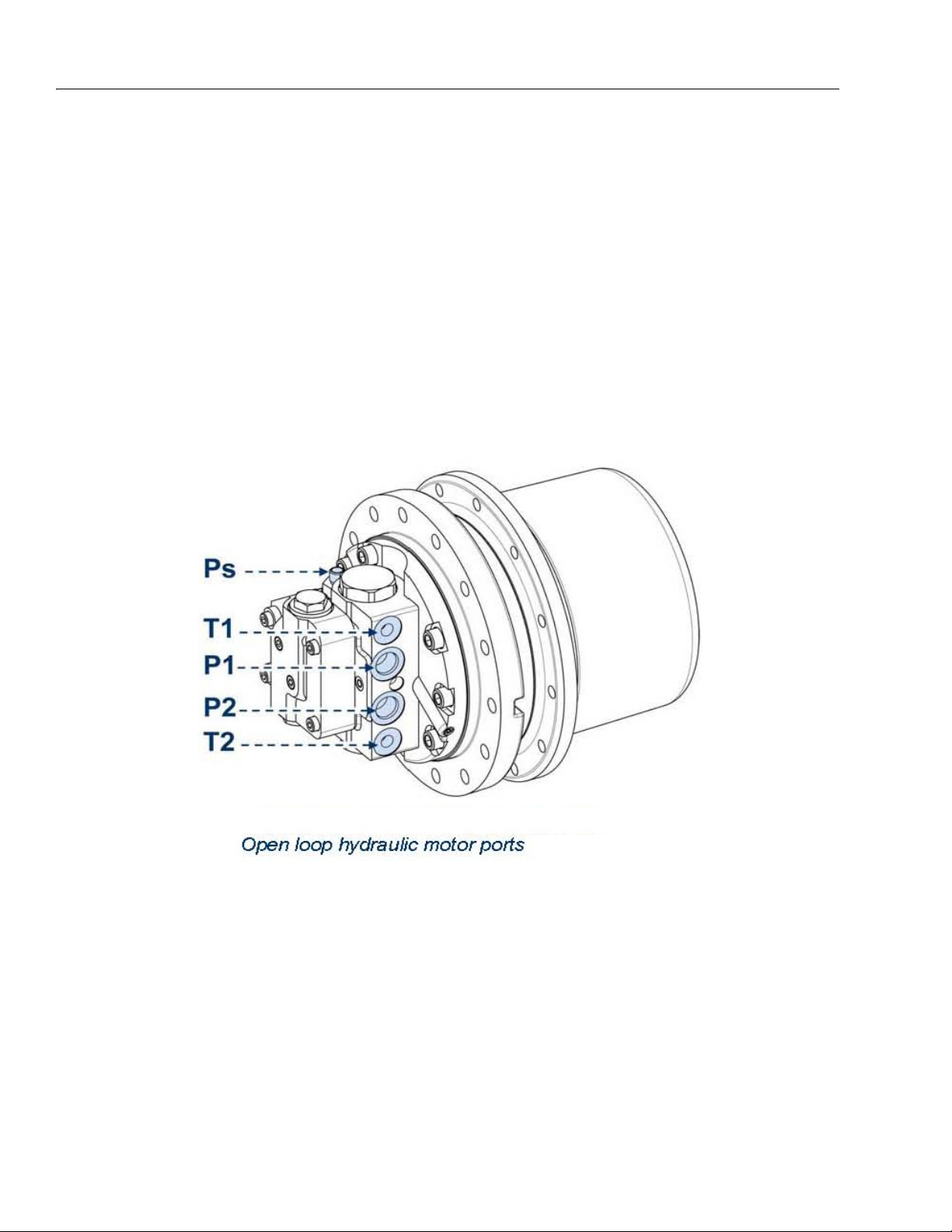
CONNECTION OF THE HYDRAULIC SYSTEM
1. Clean the surface to be connected on the hydraulic
motor.
2. Connect the hoses to the hydraulic motor ports (for
hoses sizes and dimensions refer to the installation
drawing).
Motor open loop hydraulic circuit
a. Service ports: P1-P2
b. Drain port: T1 or T2
c. 2 speed control port: Ps
3-18 – JLG Lift – 3121623

GEARBOX LUBRICATION
The motor and the gearbox have separate lubrication. The
gearbox is lubricated by oil splashing. The recommended oil
type has to be EP characteristics according to
MIL-L-2105 C & API GL5.
For standard working conditions, the recommended oil is:
For heavy duty working conditions (high loads, high duty
cycles or high ambient temperatures), the recommended oil
is:
SECTION 3 - CHASSIS & TURNTABLE
In the following table the most common brands of lubricant
and the types recommended are shown.
DURING THE OPERATION THE OIL TEMPERATURE MUST NOT
EXCEED 85-90° C INTERMITTENT.
IN CASE OF LUBRICATION WITH SYNTHETIC OILS, IS RECOMMENDED TO USE ONLY OILS WITH PAO BASE IF NOT OTHERWISE SPECIFIED WHEN ORDERING. DO NOT MIX TOGETHER
OILS OF DIFFERENT BRANDS OR CHARACTERISTICS. USE OILS
LISTED IN THE TABLE OR SIMILAR PRODUCTS WITH EQUIVALENT CHARACTERISTICS IN ORDER TO NOT MODIFY THE BRAKE
PERFORMANCES (IF PRESENT).
For information about characteristics of lubricating oils and
their proper use, please consult the lubricant suppliers
directly.
3121623 – JLG Lift – 3-19

SECTION 3 - CHASSIS & TURNTABLE
Figure 3-27.
3-20 – JLG Lift – 3121623

SECTION 3 - CHASSIS & TURNTABLE
OIL FILLING
THE GEARBOX IS SUPPLIED WITHOUT OIL; ANYWAY IT HAS
FILLING, DRAINING AND OIL LEVEL PLUGS. BEFORE PUTTING
THE GEARBOX INTO OPERATION, IT IS NECESSARY TO FILL IT
WITH OIL.
Proceed according to the following instructions:
1. Check that the gearbox axis is horizontal. Rotate the
gearbox housing until the drain plug (1A) is on the
bottom of the vertical axis of the end cover.
2. Unscrew the fill and level oil plugs (1A-1B).
3. Add the lubricating oil from the hole (1A) with the
features listed in section "Gearbox lubrication" untill
it flows out from the level hole (1B).
4. Screw the filling and level oil plugs (1A-1B)
5. Run the gearmotor, after a few minutes, stop and
check the oil level.
6. If necessary, refill with lubricant oil.
OIL DRAINING AND REPLACEMENT
1. Check that the gearbox axis is horizontal. Rotate the
gearbox housing until the drain plug (1B) is on the
bottom of the vertical axis of the end cover.
REMOVE THE OIL PLUGS WITH EXTREME CAUTION
BECAUSE AN OVERPRESSURE INSIDE THE UNIT
COULD STRONGLY EXPEL THEM.
2. Unscrew the plugs (1A-1B) and let the oil flow in a
large enough container; in order to facilitate the
draining must be oil still warm.
3. Wait a few minutes until all the oil is drained and
then proceed to screw on the plugs (1A-1B).
4. Proceed with the oil fill-up according to the following
procedures listed in Section "Oil filling".
For further information see the installation drawing.
Tighten the plugs by a torque wrench at a torque shown on
the table in the end of this manual.
DO NOT DISPOSE OF THE OIL IN THE NATURAL ENVIRONMENT
BUT BE CAREFUL TO ELIMINATE IT IN COMPLIANCE WITH THE
RELATIVE RULES AND REGULATIONS THAT GOVERN LOCALLY.
CHECK THE CORRECT OIL LEVEL AFTER FILLING THROUGH THE
APPROPRIATE PLUG.
Oil quantity to fill the gearbox is indicated on the following
table or on the product installation drawing (Indicative
values).
Believe are reported the standard gearbox oil filling draining
sketches.
3121623 – JLG Lift – 3-21

SECTION 3 - CHASSIS & TURNTABLE
NOTE: Oil qt. (l ± 10%): 0,3 l
FILL, LEVEL AND DRAIN OIL PLUG DIMENSIONS ARE INDICATED
ON THE PRODUCT INSTALLATION DRAWING.
For gearboxes with filling and draining oil hub side, refer to
the installation drawing.
3-22 – JLG Lift – 3121623

SECTION 3 - CHASSIS & TURNTABLE
TROUBLESHOOTING
The following table is a guideline to identify the troubles in
the track drive.
Ta b l e 3 - 5 .
Anomalies Causes Remedies
External oil leakage:
From the lifetime seal a) Lifetime damaged a) Replace lifetime seal
From the end cover a) O-ring seal damaged a) Replace O-ring seals
From the plugs of the cover a) Plug seal damaged
b) Plugs or screws loose
From hydraulic motor a) O-ring seals damaged
b) Plugs or screws loose
a) Replace plug seal
b) Tighten the plugs/screws
a) Replace O-ring seals
b) Tighten the plugs/screws
c) Internal motor parts damaged
Too much noise:
Inside the hydraulic motor (mechanical noise)
Hydraulic noise (during the slowing
down of the motor speed)
Inside the gearmotor (reductions) a) Internal damage a) Check the gearbox
Overheating a) Insufficient oil level
Insufficient power a) Internal motor parts damaged
Insufficient braking torque Parking brake malfunctioning
Sprocket locked a) Hydraulic motor locked
a) Internal motor parts damaged a) Check the hydraulic motor
a) Internal motor parts damaged
b) Hydraulic circuit malfunctioning
Other:
b) Hydraulic oil too warm
c) Brake not fully released
b) Malfunctioning valves
a) Motor feed not correct
b)Low volumetric efficiency
b) Parking brake locked
c) Check the hydraulic motor
a) Check the hydraulic motor
b) Check the pressure to the motor
ports is ≥ 3 bar Verify hydraulic circuit
a) Check the oil level and refill if necessary
b) Check the hydraulic circuit
a) Check the hydraulic motor
b) Check valves
a) Check the hydraulic circuit
b) Check the hydraulic motor
a) Check hydraulic motor
b) Check the complete brake release
c) Mechanical components damaged
c) Replace damaged parts
3121623 – JLG Lift – 3-23

SECTION 3 - CHASSIS & TURNTABLE
3.5 SWING DRIVE (IMO)
TECHNICAL DATA – TYPE PLATE
Figure 3-28. Type plate
The type plate is on the housing and contains the following information:
•Manufacturer
• Drawing no./type
• Identification code consisting of:
• Order number, year of manufacture and consecutive
number
•Module
• Web address
Structure and function
BRIEF DESCRIPTION
Slew drives are used for concurrent transmission of axial
and radial forces, as well as transmission of tilting
moments. Slew drives consist of a ball or roller slewing
ring, hydraulic or electric drives, and a completely enclosing housing. Force is transmitted to the mounting structure through bolts. For this purpose through holes or
threads are provided in the inner and outer ring.
Figure 3-29. Slew drive WD-L
1. Connection for options: Potentiometer, permanent
brake or front-end brake
2. Worm shaft
3. Lubricating nipple
4. Ball slewing ring
5. Option: Drive motor
6. Bolted unions for the mounting structure
7. Housing
8. Lubricating nipple
3-24 – JLG Lift – 3121623

TRANSPORTING UNPACKED SLEW DRIVES
SECTION 3 - CHASSIS & TURNTABLE
Attachment:
1. Screw the 3 eye bolts into the 3 threads that are dis-
tributed uniformly on the circumference of the slew
drive.
SCREW IN THE EYE BOLTS TO THE FULL THREAD LENGTH!
IMPROPERLY ATTACHED, UNSUITABLE, OR DAMAGED EYE
BOLTS MAY CAUSE THE SLEW DRIVE TO FALL AND CAUSE LIFETHREATENING INJURIES.
2. Attach lifting gear to the eye bolts.
3. Start the transport.
Figure 3-30. Use suitable lifting gear/never transport
product vertically
Unpacked slew drives can be transported with lifting gear
when using eye bolts under the following conditions
• The lifting gear must be configured appropriately for
the weight of the transport units.
• The ring bolts must be configured appropriately for the
weight of the transport unit.
• The slew drive shall only be transported by itself, without attached parts.
• Maintain the insertion depth prescribed by the manufacturer.
• If insertion depth is not prescribed, then a minimum
insertion depth of 1.5 x the bolt diameter must be
selected.
• Transport within the company shall only be executed
horizontally.
POSITIONING THE SWING DRIVE
4. Determine the main load-carrying zone. The main
load-carrying zone is that area of the slewing ring
that is subject to the highest load, taking all aggressive forces and torques, and all occurring load
cases into account.
5. Arrange the hardness gap of the bearing ring
charged with point load so that it is offset by 90° relative to the main load-carrying zone. The main loadcarrying zone is in the main slewing range.
THE HARDNESS GAP OR THE FILLING PLUG IN A SLEWING RING
CONSTITUTE A ZONE OF DECREASED LOAD-CARRYING CAPACITY. THE SERVICE-LIFE OF THE SLEW DRIVE WILL BE REDUCED
SIGNIFICANTLY, IF THE HARDNESS GAP IS IN THE MAIN SLEWING RANGE. FRACTURE OF BEARING RING FOR EXAMPLE MAY
CAUSE SLEW DRIVE FAILURE. CONSEQUENTLY PLACE THIS
MARKED POINT IN A REDUCED LOAD ZONE IF POSSIBLE.
6. Use a feeler gauge to check whether the support
surface of the slew drive is completely supported by
the mounting structure. If this is not the case, the
support surface of the mounting structure must be
reworked.
Figure 3-31. Always use the full length of the thread
3121623 – JLG Lift – 3-25

SECTION 3 - CHASSIS & TURNTABLE
7.
Figure 3-32. Check the support surface
BOLTING THE SLEW DRIVE
DO NOT USE IMPACT SCREWDRIVERS. USING AN IMPACT
SCREWDRIVER MAY CAUSE IMPERMISSIBLE DEVIATIONS
BETWEEN THE BOLT TIGHTENING FORCES. FAILURE OF THE
BOLTED UNION WITH THE MOUNTING STRUCTURE MAY CAUSE
SEVERE PERSONAL INJURY OR MATERIAL DAMAGE.
MOUNT THE SLEW DRIVE IN UNSTRESSED STATE.
Strictly comply with the procedure specified below to
avoid impermissible deviations between the bolt tightening forces:
FIRST FASTEN THE HOUSING, THEN FASTEN THE
TOOTHED BEARING RING!
8. Use medium strength Loctite (Loctite 243) on
screws.
9. Pretension the bolts, with washers if required, crosswise in 3 steps, 30%, 80%, and 100% of the tightening torque, or the hydraulically applied pretension
force.
10. In this process turn the unscrewed ring several
times. Repeat the procedure for the bearing ring that
has not yet been bolted.
Figure 3-33. Tighten crosswise
Ta b l e 3 - 6 .
Mounting
bolt dimen-
sions
Mounting pretension force
1)
F
M
Strength class 10.9 in
kN lbs
M24 282 63396
M27 367 82505
M30 448 100714
M33 554 124544
M36 653 146800
M42 896 201429
M45 1043 234476
M48 1177 264600
M52 1405 315857
M56 1622 364640
M60 1887 424215
M64 2138 480642
M68 2441 548759
If using a hydraulic bolt-tensioning cylinder the tensioning
forces for the bolt pretension should not exceed 90% of
yield strength.
3-26 – JLG Lift – 3121623

SECTION 3 - CHASSIS & TURNTABLE
1)
FM for hydraulic bolt-tensioning cylinder pretension ed
to 85% of yield strength.
Table 3-7.
Mounting
bolt dimen-
sions
Mounting pretension force
1)
F
M
Strength class 10.9 in
kN lbs
1 – 8 UNC 301 67668
1 1/8 – 7 UNC 379 85203
1 1/4 – 7 UNC 481 108133
1 3/8 – 6 UNC 573 128816
1 1/2 – 6 UNC 697 156692
1 5/8 – 6 UNC 832 187041
1 3/4 – 5 UNC 942 211770
1)
FM for hydraulic bolt-tensioning cylinder pretensioned
to 85% of yield strength.
3. Main load-carrying zone
4. Lower mounting structure
Figure 3-35. Measurement setup
5. Dial gauge
6. Upper mounting structure
7. Slew Drive
8. Lower mounting structure
DETERMINING THE TILTING CLEARANCE
Tilting clearance increases as raceway system wear
increases. To determine the increase in tilting clearance a
basic measurement must be executed in installed status
and prior to first-time operation. This is the only way to
determine changes.
Figure 3-34. Determine tilting clearance
1. Upper mounting structure
2. Tilting direction
Procedure:
Tilting clearance measurement
9. Switch off the system and safeguard it from being
turned on again.
10. Permanently mark the measuring point in the main
load direction on the housing and on the bearing
ring.
11. Attach the dial gauge as shown in Fig. 24.
12. Apply defined tilt torque, at least 50% of max. oper-
ating load, in direction "A".
13. Set dial gauge to zero.
14. Apply defined tilt torque, at least 50% of max. oper-
ating load, in direction "B". The displayed measured
value m1 corresponds to the existing tilting clearance and serves as the base value that will be used
for comparison in later inspections.
15. Log and document all measured values.
• All inspections at a later point in time must be executed
on the same measuring point, with the same loads, at
the same relative position of the bearing rings, and in
the same sequence.
• At pure axial or radial load check the tilting clearance
by applying an additional tilting load.
3121623 – JLG Lift – 3-27

SECTION 3 - CHASSIS & TURNTABLE
MAINTENANCE SCHEDULE
Maintenance tasks are described in the sections below
that are required for optimal and trouble-free operation.
If increased wear is detected during regular inspections,
then reduce the required maintenance intervals according
to the actual indications of wear.
If you have questions concerning maintenance tasks and
intervals, please contact our customer service.
Interval Maintenance task To be executed by
weekly Check seal Qualified person
after 250 operating hours Check tighten bolts Qualified person
Check tilting clearance Qualified person
after every additional
500 operating hours or at
least every 6 months
Check tighten bolts
• Reduce the inspection interval if there is heavy wear or
continuous operation.
Check tilting clearance
• Reduce the inspection interval to 200 operating hours if
the detected increase in tilting clearance is approximately 75% of the permissible tilting clearance increase.
• After further increase reduce the interval between inspections to 50 - 100 hours.
Check circumferential backlash
• Reduce the inspection interval to 200 operating hours if
the detected increase in circumferential backlash is
approximately 75% of the permissible circumferential
backlash increase.
• After further increase reduce the interval between inspections to 50 - 100 hours.
Qualified person
Qualified person
Qualified person
Lubrication
General re-lubrication of slew drives:
• After each cleaning
• Before and after longer periods of standstill, e.g. for
cranes and construction machines during the winter
months.
IMPORTANT
THE MAIN CAUSE FOR SLEWING RING FAILURE IS
INADEQUATE LUBRICATION. THE LUBRICATION
INTERVALS ESSENTIALLY DEPEND ON EXISTING
WORKING AND ENVIRONMENTAL CONDITIONS, AS
WELL AS THE VERSION OF THE SLEW DRIVE. PRECISE LUBRICATION INTERVALS CAN ONLY BE
DETERMINED BY TESTS UNDER NORMAL OPERATING CONDITIONS.
3-28 – JLG Lift – 3121623

If comparable results are not available, the following table
can be used as a guide value:
Work conditions Lubricating interval To be executed by
Dry and clean workshop hall (rotary
tables, robots, etc.)
Severe conditions on open terrain
(cranes, excavators, etc.)
Aggressive climatic conditions,
(ocean, desert, arctic climate,
extremely polluted environment,
operating hours per week
Extreme conditions (tunnel boring
machines, steel works, wind turbines)
The specified values are valid for the following conditions:
• Operating temperature on the slew drive < 70° C (158°
F).
• Circumferential speed < 0.5 m/s (1.64 ft/sec) for SP
slew drives.
• Output speed < 5 rpm for WD slew drives.
• Low to moderate load.
Approx. every 300 operating hours, at
Approx. every 100 to 200 operating
hours, at least every 4 months
Every 50 operating hours, at least
≥70
Continuous lubrication (through cen-
tral lubrication or grease cups)
SECTION 3 - CHASSIS & TURNTABLE
Specialist
least every 6 months
Specialist
Specialist
every
2 months
Specialist
COMPLY WITH THE INSTRUCTIONS IN THE OPERATING MANUAL PROVIDED BY THE MANUFACTURER, FOR LUBRICATION OF OPTIONAL
INTERMEDIATE GEAR UNITS, BRAKES, AND
MOTORS.
IF NECESSARY RE-LUBRICATE PERMANENT
BRAKES. FOR THIS ONLY USE THE SPECIAL GREASE
SHELL RETINAX HDX2.
3121623 – JLG Lift – 3-29

SECTION 3 - CHASSIS & TURNTABLE
MAINTENANCE TASKS
INSPECTING THE MOUNTING BOLTS
IMPORTANT
TO COMPENSATE FOR SETTLING, THE BOLTS MUST
BE RETIGHTENED WITH THE PRESCRIBED TIGHTENING TORQUE. RETIGHTENING MUST BE EXECUTED WITHOUT EXERTING ADDITIONAL
EXTERNAL STRESS ON THE BOLTED UNION.
Figure 3-36. Inspecting the mounting bolts
1. Detached bolt
CHECKING THE TILTING CLEARANCE
Wear in the raceway system results in an increase in tilting
clearance. Consequently it is necessary to check the tilting clearance in accordance with the maintenance intervals.
IF THE MAXIMUM PERMISSIBLE TILTING CLEARANCE INCREASE
IS REACHED, THEN THE SYSTEM MUST BE BROUGHT TO A
STANDSTILL AND THE SLEW DRIVE MUST BE REPLACED IMMEDIATELY, AS SAFE OPERATION CAN NO LONGER BE ENSURED.
Checking the tilting clearance increase dk directly on
the slew drive
The measured value m1 determined at installation serves
as the base value ("Determination of tilting clearance").
• Determine the value mx as described in the "Determining the tilting clearance".
• Subtract the base value m1 from the value mx determined in the inspection measurement:
= mx – m1 ≤ dkperm
d
k
d
perm = 0.45 mm
k
d
perm = 0.0177 in
k
Execution only by a specialist.
• Special tools required:
Torque wrench
Hydraulic clamping fixture
• Replace loose and detached bolts or nuts and washers
with new bolts, nuts and washers.
• Use the same bolt size and bolt quality.
IF A HYDRAULIC CLAMPING FIXTURE WAS USED TO
TIGHTEN THE BOLTS, THEN A HYDRAULIC CLAMPING FIXTURE MUST ALSO BE USED TO CHECK THE
BOLT PRETENSION. ALWAYS USE THE SAME TIGHTENING PROCEDURE AS SPECIFIED FOR INSTALLATION OF THE SLEW DRIVE WHEN CHECKING THE
BOLTED UNION.
Checking the tilting clearance increase dk but not
directly on the slew drive
Proportionally convert the tilting clearance increase each
time a measurement is taken (after the installation measurement) and compare with d
perm.
k
3-30 – JLG Lift – 3121623

LUBRICATING THE SLEW DRIVE
IMPORTANT
REGULARLY LUBRICATE THE SLEW DRIVES TO
PROLONG THEIR SERVICE LIFE AND ENSURE SAFE
OPERATION.
IMPORTANT
ALWAYS USE THE LUBRICANTS SPECIFIED IN THE
ORDER DRAWING. IF USING OTHER LUBRICANTS
PAY ATTENTION TO THE RELATIVE MIX ABILITY
OF THE SUBSTANCES. THE STANDARD LUBRICANTS
USED ARE "R.TECC NORPLEX LKP2" FROM RHENUS,
OR THE GREASE "OPTIMOL LONGTIME PD0" FROM
CASTROL. IF IN DOUBT, OR IF THERE IS NO SPECIFICATION ON THE DRAWING, CONSULT WITH OUR
CUSTOMER SERVICE. USING THE WRONG LUBRICANT MAY CAUSE DAMAGE TO THE SLEW DRIVES
AND REDUCE THE SERVICE LIFE. IN THIS CASE, ANY
WARRANTY SHALL BE EXCLUDED. COMPLY WITH
THE INSTRUCTIONS PROVIDED BY THE LUBRICANT
MANUFACTURER!
SECTION 3 - CHASSIS & TURNTABLE
Figure 3-37. Lubricating the slew drive
1. Fresh lubricant
2. Lubricating nipple, bearing ring
3. Lubricating ring housing
If possible use a central lubrication system to lubricate the
raceway system. In this regard ensure that the hoses are
filled with grease at commissioning and that the storage
tanks are regularly topped up with grease.
An automatic re-lubricating system significantly facilitates re- lubrication for the raceway system and the
toothing. Functional safety as well as wear behavior
are improved.
Comply with the instructions in the operating manual
provided by the respective manufacturer for lubrication of optional intermediate gear units, brakes, and
motors.
If it is evident that moisture has penetrated into the
slew drive, or has been absorbed by the grease, you
must re-lubricate more intensively.
4. In succession, press grease into all lubricating nipples while simultaneously turning the slew drive all
the way through, until a continuous collar of grease
forms under at least one seal.
5. Ensure that old lubricant can escape without
obstruction.
Inspecting the seals
IMPORTANT
DAMAGED SEALS MUST BE REPLACED IMMEDIATELY. IF THERE IS CORROSION DAMAGE OR FUNCTIONAL IMPAIRMENT A CONSEQUENCE OF
DAMAGED SEALS NOT BEING REPLACED AT THE
PROPER TIME, ANY WARRANTY SHALL BE
EXCLUDED. PENETRATING MOISTURE MAY
QUICKLY CAUSE CORROSION IN THE BEARING
RING AND IMPAIRS SAFE OPERATION. NOTE THAT
THE FACTORY-INSTALLED SEAL ONLY OFFERS
PROTECTION AGAINST DUST AND SPLASHING
WATER.
If damage is detected on a seal, contact the customer service organization without delay.
3121623 – JLG Lift – 3-31

SECTION 3 - CHASSIS & TURNTABLE
ENGINE SERIEL NUMBER
3.6 HONDA ENGINE IGX440
SERIAL NUMBER LOCATION
The engine serial number is stamped on the cylinder barrel. Refer to this when ordering parts or making technical
inquiries.
3-32 – JLG Lift – 3121623

SECTION 3 - CHASSIS & TURNTABLE
SPECIFICATIONS
DIMENSIONS AND WEIGHT
Model iGX440U
PTO types S Q V
Overall length 407 mm (16.0 in) 433 mm (17.0 in) 450 mm (17.7 in)
Overall width 505 mm (19.9 in)
Overall height 454 mm (17.9 in)
Maximum angle of inclination 20°
Dry weight 39 kg (86 lbs)
Operating weight 45 kg (99 lbs)
ENGINE
Model iGX440U
Description code GCAWK
Type 4-stroke, overhead camshaft, single cylinder, inclined by 15°
Displacement
438 cm3 (26.7cu-in)
Bore x stroke 88.0 x 72.1 mm (3.46 x 2.84 in)
Maximum horsepower
Recommended maximum operation bhp
Maximum torque
11.2 kW (15.2 PS) / 3,600 min
8.0 kW (10.8 PS) / 3,600 min
29.8 N·m (3.0 kgf·m, 22 lbf·ft)/2,500 min
-1
-1
(rpm)
(rpm)
-1
(rpm)
Compression ratio 8.1 : 1
Minimum fuel consumption 328 g/kW·h (241 g/PS·h, 0.53 lb/PS·h)
Ignition system CDI
Ignition timing (at no load)
10° B.T.D.C./1,400 min
13° B.T.D.C./3,600 min
-1
-1
(rpm)
(rpm)
Spark plug BKR7E-E (NGK), K22PR-UR (DENSO)
Lubrication system Forced splash type
Oil capacity 1.10 l (1.16 US qt, 0.97 lmp qt)
Cooling system Forced air
Starting system Recoil and starter motor
Stopping system Ignition primary circuit open
Carburetor Horizontal type batter fly valve
Air cleaner Dual element type
Governor STR (Self Tuning Regulator) governor
Fuel used Unleaded gasoline with a pump octane rating 86 or higher
Fuel tank capacity 6.5 l (1.72 US gal, 1.43 lmp gal)
3121623 – JLG Lift – 3-33

SECTION 3 - CHASSIS & TURNTABLE
WIRING DIAGRAMS
With starter motor and charge coil (20A) type
3-34 – JLG Lift – 3121623

TROUBLESHOOTING
SELF-DIAGNOSIS AS INDICATED BY THE LED
When the battery is disconnected, self-diagnosis with the
LED is not possible.
The LED for a failure flashes periodically, as shown in the
following figure.
Example: in the case of "2 flashes” the sequence of 0.3
sec. on > 0.3 sec. off > 0.3 sec. on > 1.5 sec. off is
repeated as a cycle.
SECTION 3 - CHASSIS & TURNTABLE
3121623 – JLG Lift – 3-35
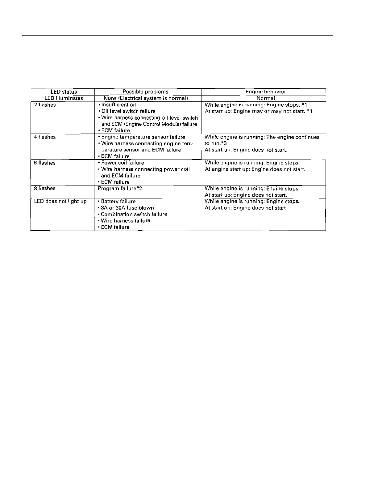
SECTION 3 - CHASSIS & TURNTABLE
*1: The engine may or may not stop, depending on the
program in the EDCM.
*2: Rewriting of the program is needed. Contact your
Honda engine distributor.
*3: If the faulty engine temperature sensor is detected
while engine is running, the engine does not stop and the
LED does not flash.
After the engine is stopped, the engine does not start until
the faulty engine temperature sensor is solved.
3-36 – JLG Lift – 3121623

a. Engine does not start (starter motor equipped type).
SECTION 3 - CHASSIS & TURNTABLE
3121623 – JLG Lift – 3-37

SECTION 3 - CHASSIS & TURNTABLE
b. Engine does not start with LED flashing
3-38 – JLG Lift – 3121623
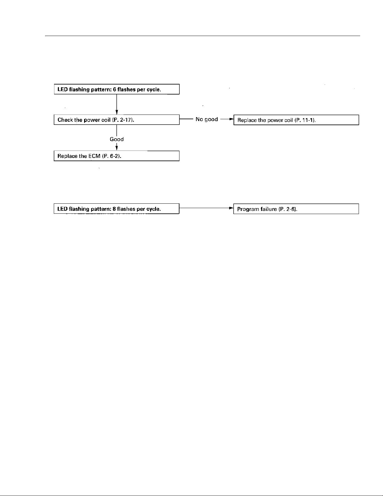
SECTION 3 - CHASSIS & TURNTABLE
3121623 – JLG Lift – 3-39

SECTION 3 - CHASSIS & TURNTABLE
c. LED is lit but engine does not start (starter motor
equipped type) / engine does not start (starter motor
equipped type)
3-40 – JLG Lift – 3121623

SECTION 3 - CHASSIS & TURNTABLE
3121623 – JLG Lift – 3-41
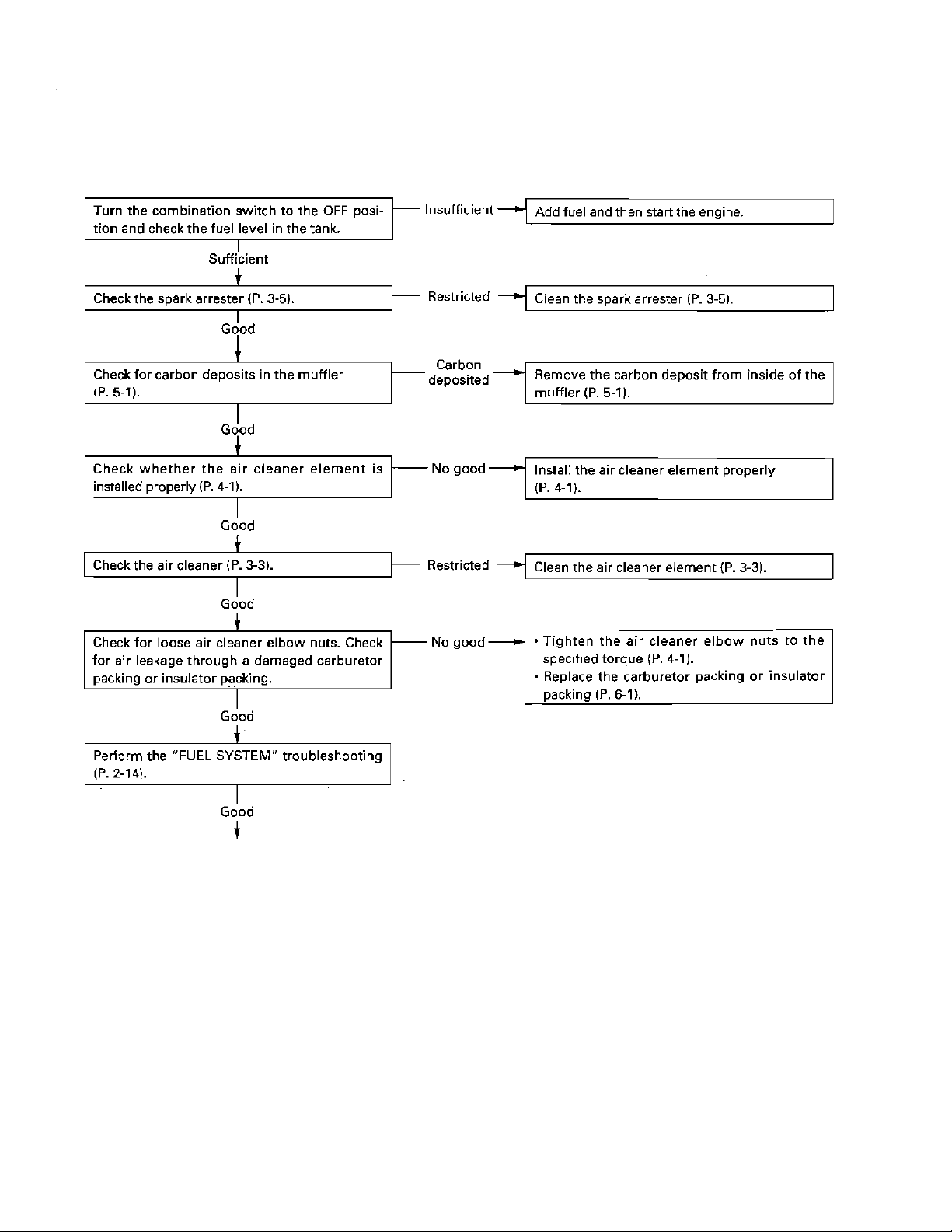
SECTION 3 - CHASSIS & TURNTABLE
d. Engine speed does not increase or engine lacks
power
3-42 – JLG Lift – 3121623

SECTION 3 - CHASSIS & TURNTABLE
3121623 – JLG Lift – 3-43

SECTION 3 - CHASSIS & TURNTABLE
e. Fuel system
3-44 – JLG Lift – 3121623

SECTION 3 - CHASSIS & TURNTABLE
3121623 – JLG Lift – 3-45

SECTION 3 - CHASSIS & TURNTABLE
f. Ignition system
3-46 – JLG Lift – 3121623

COILS AND IGNITION SWITCHES CHECK
P. 2 -1 9
SECTION 3 - CHASSIS & TURNTABLE
3121623 – JLG Lift – 3-47

SECTION 3 - CHASSIS & TURNTABLE
3-48 – JLG Lift – 3121623

SPARK TEST
GASOLINE IS HIGHLY FLAMMABLE AND EXPLOSIVE. YOU CAN
BE BURNED OR SERIOUSLY INJURED WHEN HANDLING FUEL.
KEEP HEAT, SPARKS AND FLAME AWAY. HANDLE FUEL ONLY
OUTDOORS. WIPE UP SPILLS IMMEDIATELY.
DO NOT OPERATE THE STARTER MOTOR FOR MORE THAN 5
SECONDS AT ONE TRY. IF STABLE COMPRESSION IS NOT
OBTAINED WITHIN 5 SECONDS, STOP THE STARTER MOTOR AND
WAIT 10-20 SECONDS TO ALLOW THE STARTER MOTOR TO
COOL, AND REPEAT THE OPERATION AGAIN.
1. Loosen the carburetor drain screw to drain the carburetor througly.
2. Remove the spark plug cap from the spark plug.
3. Remove the spark plug from the cylinder.
4. Crank the engine several times to expel unburnt
gas.
5. Attach the spark plug cap to the spark plug.
6. Ground negative (-) electrode (i. e. threaded part) of
the spark plug against the cylinder side head cover
bolt.
SECTION 3 - CHASSIS & TURNTABLE
With recoil starter type:
Pull the recoil starter to check whether sparks jump
across the electrodes.
With starter motor type:
Turn the combination switch to the "START" position
to check whether sparks jump across the electrodes.
3121623 – JLG Lift – 3-49

SECTION 3 - CHASSIS & TURNTABLE
HARNESS ROUTING
3-50 – JLG Lift – 3121623

SECTION 3 - CHASSIS & TURNTABLE
3121623 – JLG Lift – 3-51
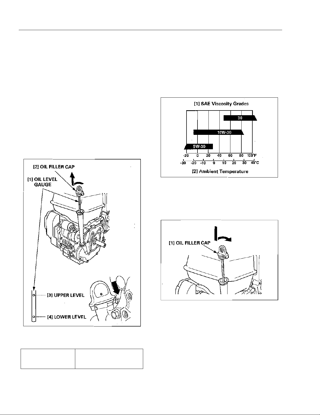
SECTION 3 - CHASSIS & TURNTABLE
ENGINE OIL
Oil level check:
1. Place the engine on a level surface.
2. Turn the oil filler cap counterclockwise 90 degrees to
unlock the cap and remove the oil level gauge from
the oil filler neck. Wipe the oil level gauge clean.
3. Insert the oil level gauge without screwing it into the
oil filler neck. Remove the oil filler cap and check the
oil level shown on the oil level gauge.
4. If the oil level is near or below the lower level mark
on the oil level gauge, fill with the recommended oil
to the upper level mark.
Oil is a major factor affecting performance and service life.
Use 4-stroke automotive detergent oil.
SAE 10W-30 is recommended for general use. Other viscosities shown in the chart may be used when the average temperature in your area is within the recommended
range.
Insert the oil level gauge into the oil filler neck and turn the
oil filler cap clockwise 90 degrees to lock the cap.
Recommended oil
SAE 10W-30
API Service classification
SE, SF or SG
3-52 – JLG Lift – 3121623

SECTION 3 - CHASSIS & TURNTABLE
Oil change:
5. Check the engine on a level surface and remove the
oil filler cap.
6. Remove the oil drain bolt and sealing washer. and
drain the oil into a suitable container.
Please dispose of used motor oil in a manner that is
compatible with the environment. We suggest you
take use oil In a sealed container to your local recycling center or service station for reclamation. Do
not throw it in the trash. pour it into the ground, or
down a drain.
USED ENGINE OIL CONTAINS SUBSTANCES THAT HAVE BEEN
IDENTIFIED AS CARCINOGENIC. IF REPEATEDLY LEFT IN CONTACT WITH THE SKIN FOR PROLONGED PERIODS, IT MAY CAUSE
SKIN CANCER. WASH YOUR HANDS THOROUGHLY WITH SOAP
AND WATER AS SOON AS POSSIBLE AFTER CONTACT WITH
USED ENGINE OIL.
AIR CLEANER
Cleaning:
A dirty air cleaner will restrict air flow to the carburetor,
reducing engine performance. If the engine is operated in
dusty areas, clean the air cleaner more often than specified In the MAINTENANCE SCHEDULE.
1. Remove the air cleaner cover nut and air cleaner
cover.
2. Remove the wing nut, air cleaner elements (paper
element and foam element) and air cleaner elbow
packing, and separate them. Carefully check both
elements for hole, or tear: and replace if damaged.
Check the air cleaner claw packing for deterioration
or damage.
7. Tighten the oil drain bolt and a new sealing washer
to the specified torque.
TORQUE: 45 N·m (4.5 kgf·m, 33 lbf·ft)
8. Refill with the commended oil.
Engine oil capacity 1.10 l (1.16 US qt, 0.97 lmp qt)
9. Check the oil level and, if the oil level is near or
below the lower limit mark on the oil level gauge, fill
with the recommended oil to the upper level mark.
10. Install the oil filler cap.
3. Foam element: Clean the element in warm soapy
water, rinse and allow to dry thoroughly, or clean
with a Nigh flash point solvent and allow to dry thoroughly. Dip the element in clear engine oil and
squeeze out all the excess oil. Excess oil will restrict
3121623 – JLG Lift – 3-53

SECTION 3 - CHASSIS & TURNTABLE
air flow through the form element and may cause
the engine to smoke at startup.
4. Paper element: Tap the element lightly several times
on a hard surface to remove excess dirt or blow
compressed air lightly 207 kPa (2.1 kgf/cm2, 30 psi)
or less) through the falter from the inside out. Never
try to brush the dirt off; brushing will force dirt into
the fibers.
SPARK PLUG
Inspection/cleaning:
If the engine has been running, the engine will be very hot
Allow it to coo! before proceeding.
1. Remove the spark plug cap and remove the spark
plug using spark plug wrench.
2. Visually inspect the spark plug. Discard the plug if
the insulator is cracked of chipped.
5. Wipe dirt from the inside of the air cleaner elbow and
all cleaner cover, using a rag. Be careful to prevent
dirt frond entering the air duct that leads to the carburetor.
6. Install the foam element to the paper element. Install
the air cleaner elbow packing and air cleaner ale'
mints, and tighten the wing nut securely.
Install the air cleaned cover and tighten the air
cleaned cover nut securely.
OPERATING THE ENGINE WITHOUT THE AIR CLEANER ELEMENT
OR WILT THE ELEMENT INSTALLED LOOSELY WITH ALLOW DIRT
TO ENTER THE ENGINE, CAUSING RAPID ENGINE WEAR. INSTALL
THE AIR CLEANER ELEMENT SECURELY.
3. Remove carbon and other deposits with a plus
cleaner or stiff wire brush. Check the sealing washer
for damage.
Spark plug BKR7E-E (NGK) K22PR-UR
(DENSO)
4. Measure the plug gag with a wire-type feeler gauge.
If the measurement is outside the specification,
adjust by bending the side electrode.
3-54 – JLG Lift – 3121623

SECTION 3 - CHASSIS & TURNTABLE
Plug gap 0.7 - 0.8 mm (0.028-0.031 in)
5. Install the spark plug fingerings to beat the washer,
and then tighten with a plug wrench. If reinstalling
the used spark plug, tighten 1/8-1/4 turf after the
spark plug seats. If installing a new spark plug,
tighten 1/2 turn after the spark plug seats.
TORQUE: 18 N·m (1.8 Kgf·m, 13 lfb·ft)
SPARK ARRESTER
Cleaning:
THE ENGINE AND MUFFLER BECOME VERY HOT DURING OPERATION AND THEY REMAIN HOT FOR A WHILE AFTER OPERATION.
BE SURE THAT THE ENGINE IA COOL BEFORE MUFFLER
REMOVAL/INSTALLATION.
A LOOSE SPARK PLUG OWN INCOME VET HOT AND CAN DALES,
THE ENGINE. OVERTIGHTENING CAN DAMAGE THE THREADS IN
THE CYLINDER BLOCK.
6. Install the spark plug cap securely.
1. Remove the spark arrester from the muffler.
2. Clean the carbon deposits. from the spark arrester
screed with a brush.
3. Check the spark arrester screen for damage. If the
gnarl arrester is damaged, replace it.
4. Rainfall the spark arrester to the muffler.
3121623 – JLG Lift – 3-55

SECTION 3 - CHASSIS & TURNTABLE
VALVE CLEARANCE
Inspection/adjustment:
Valve clearance inspection and adjustment must be per
formed with the engine cold.
1. Remove the cylinder head cover.
2. With recoil starter type:
Set the piston at top dead center of the compression
stroke (both' valves fully closed) by pulling the recti
starter slowly. The ''∆'' mark on the starter pulley wit
align with the projection on the fan cover when the
pastor is at top dead center of the compression
stroke.
Without retool starter type:
sit the piston at top dead center of the compression
stroke (both valves fully closed) by turning the cooling fan setting plate. The projection of the cooling
fan will align with the projection on the fan cover
when the piston is at top dead center of the compression stroke.
3. Insert a feeler gauge between the rocker arm and
valve to measure valve clearance.
Valve clearance IN 0.12 ±0.02 mm
EX 0.15 ±0.02 mm
3-56 – JLG Lift – 3121623

SECTION 3 - CHASSIS & TURNTABLE
4. If adjustment is necessary proceed is follows:
a. Hold the tappet adjusting screw using the spe-
cial too and loosen the tappet adjusted screw
lock nut.
b. Turn the tappet adjusting screw to obtain the
specifier clearance.
c. Heighten the tappet adjusting screw lock nut
while holding the rocker arm pivot.
TORQUE: 7.5 N·m (0.75 kgf·m, 5.5 lbf·ft)
Recheck valve clearance after tightening the tappet
adjusting screw lock nut.
5. Install the cylinder head cover.
FUEL TANK
Cleaning:
GASOLINE IS HIGHLY FLAMMABLE END EXPLOSIVE. YOU CAN
RETURNED OR SERIOUSLY INJURED WHEN HANDLING FUEL.
KEEP HEAT, SPARKS AND FLORAL AWAY. HANDLE FUEL ONLY
OUTDOORS. WIPE UP SPILLS IMMEDIATELY.
• After connecting the fuel tube. Check for any sign of
fuel leakage.
1. Drain the fuel from the fuel tank into a suitable container.
Manual fuel vales type:
Drain tie fuel from the carburetor before removing
the fuel tank, proceed as follows:
a. Turn the fuel valve lever to the OFF position.
b. Loosen the drain screw of the carburetor end
drain tie fuel trio a suitable container.
2. Remove the fuel tank, tank stay and auto fuel valve
and disconnect the fuel tube from the auto feel
valve.
3. Disconnect the fuel lube end remove the fuel filter
and oaring from the fuel lank. Wash the fuel filter in
nonflammable or high flash point solvent. Inspect
the fuel filter screen to be sure it is undamaged.
4. Clean the fuel lank with nonflammable or high flash
point solvent and allow to dry thoroughly.
5. Install the fuel filter, O-ring, fuel valve, fuel tube and
fuel tank cap. Connect the fuel tube to the fuel valve
and install the fuel tank.
6. After reassembly check for fuel leaks.
3121623 – JLG Lift – 3-57

SECTION 3 - CHASSIS & TURNTABLE
FUEL TUBE
Inspection:
GASOLINE IS HIGHLY FLAMMABLE AND EXPLOSIVE. YOU CAN
BE BURNED OR SERIOUSLY INJURED WHEN HANDLING FUEL.
KEEP HEATH QUIRK: AND FLAME AWAY. HANDLE FULL ONLY
OUTDOORS. WIPE UP SPILLS IMMEDIATELY.
FUEL STRAINER CUP
Cleaning:
GASOLINE IS HIGHLY FLAMMABLE AND EXPLOSIVE. YOU CAN
BE BURNED OR SERIOUSLY INJURED WHEN HANDLING FUEL.
KEEP HEAT, SPARK AND FLAME AWAY. HANDLE FUEL ONLY
OUTDOORS. WIPE UP SPILLS IMMEDIATELY.
• After installing the fuel strainer cup, check for any sign
of fuel leakage.
• After connecting the fuel tube, check for any sign of
fuel leakage.
Check the fuel line for deterioration, damage or leakage.
Replace the fuel line if necessary.
1. Remove the fuel strainer
2. Remove the fuel cup filter and clean it.
3. Install the fuel cup filter and tighten the fuel strainer
cup to the specified torque.
TORQUE: 3.9 N·m (0.4 kgf·m, 2.9 lbf·ft)
3-58 – JLG Lift – 3121623

AIR CLEANER
REMOVAL/INSTALLATION
MUFFLER
REMOVAL/INSTALLATION
THE ENGINE AND MUFFLER BECOME VERY HOT DURING OPERATION AND THEY REMAIN HOT FOR A WHILE AFTER OPERATION.
BE SURE THE ENGINE IS COOL BEFORE MUFFLER REMOVAL/
INSTALLATION.
Remove the air cleaner.
SECTION 3 - CHASSIS & TURNTABLE
3121623 – JLG Lift – 3-59

SECTION 3 - CHASSIS & TURNTABLE
EXHAUST PIPE/MUFFLER PROTECTOR
INSTALLATION:
1. Attach a new muffler basket and exhaust pipe to the
cylinder head.
2. Move the exhaust pipe all the way to the fuel tank
side and tighten the 8 mm flange nuts.
3. Attach a new muffler gasket B and muffler to the
exhaust pipe. Tighten the I x 14 mm CT bolt on the
muller stay.
7. Keep some clearance between the exhaust slot and
the spark arrester, and tighten the other three bolts
securely.
FUEL CUT SOLENOID
Measure the resistance between the terminals.
Specified resistance
3.8 - 5.8 Ω
4. Tighten the 8 mm flange nuts to install the muffler on
the exhaust pipe.
After tightening the flange nuts. be sure the muffler
gasket and exhaust pipe are closely attached
together.
5. Put the muffler protector on the muffler and then
loosely tighten the bolts in the numbered sequence
as shown.
6. Align the center of the muffler' protector exhaust slot
wit) the reenter of. the spark arrester, and tighten the
6 x 14 mm CT bolt under the echoed! slot securely.
When 12V battery voltage is applied, check that the fuel
cut solenoid operates normally.
Check the extended length of the needle at ON (battery
connected) position and OFF (battery removed) position.
3-60 – JLG Lift – 3121623
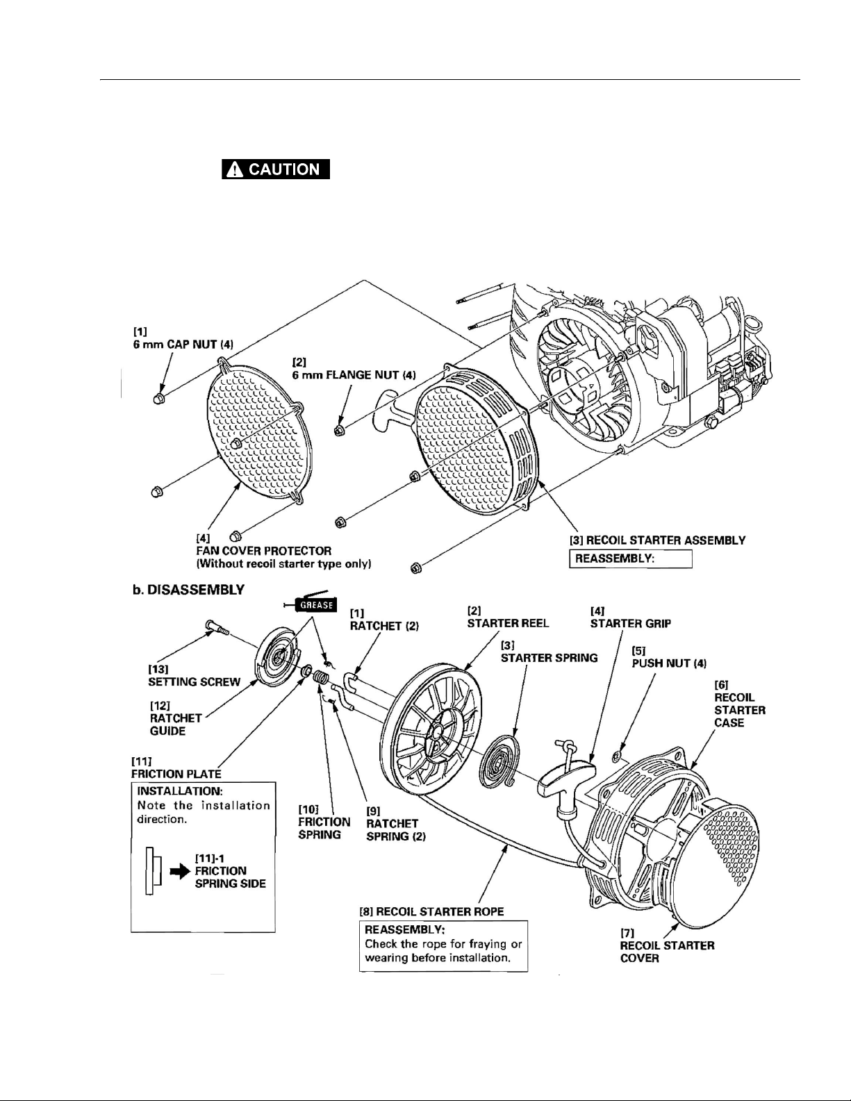
ECOIL STARTER
THE RETURN SPRING MAY BE EJECTED FROM THE HOLDER
WITH ENOUGH FORCE TO INJURE YOU. BE SURE TO RELEASE
THE TENSION ON THE RETURN SPRING BEFORE DISASSEMBLY.
REMOVAL/INSTALLATION
SECTION 3 - CHASSIS & TURNTABLE
REASSEMBLY
8. Insert the starter rope end into the. starter reel and
tie the rope as shown.
3121623 – JLG Lift – 3-61

SECTION 3 - CHASSIS & TURNTABLE
9. Wind the rope onto the reel counterclockwise and
hook the starter rope into the cutout of the starter
reel.
10. Wind the starter spring and install it to the starter reel
by aligning the outer hook to the groove of the reel.
12. Install the ratchet spring and ratchet as shown.
Apply grease to the friction spring and inside of the
ratchet guide. Install the spring end f friction plate,
and then install the ratchet guide by aligning the "
marks of the ratchet guide with the ratchets. Tighten
the setting screw securely.
13. Turn the reel three full turns counterclockwise to presoak the starter spring.
∆"
11. Apply grease to the spring hook and boss of the
starter case. Align the spring inner hook to the case
claw on the case by turning the reel counterclockwise.
3-62 – JLG Lift – 3121623

SECTION 3 - CHASSIS & TURNTABLE
14. Pass the rope through the starter case hole and
started grip and knot the end of the rope as shown.
15. Check the operation of tile ratchet by pulling the
started rope out several times.
RECTIFIER/REGULATOR RECTIFIER
Measure the resistance between the terminals.
• Use a tester that is equivalent to or higher than the performance specified:
Internal resistance: 20 Ω/VDC, 9 Ω/VAC
• Be careful not to touch the metallic part of the tester
probe with your fingers, otherwise correct resistance
value cannot be obtained.
• Read the tester manufacturer's operation instructions
carefully before operating the tester. Follow the instructions of the Service manual. Be sure the tester's battery
is fully charged and check the meter before using the
tester.
• Use the R x 1 scale of a commercially available millimeter that meter shows current flow from negative (-) to
positive (+). If the meter shows current flow in one
direction but not the other, the diode is goad.
3121623 – JLG Lift – 3-63

SECTION 3 - CHASSIS & TURNTABLE
FUSE
1. Check for. a blown fuse; replace if necessary.
2. If the replaced fuse blows out, check the following.
30A FUSE:
a. Check the combination switch.
b. Check the wire harness connecting the combi-
nation switch and ECM (Bl/Y) for open or short
circuit.
c. Check the rectifier or regulator rectifier.
3A FUSE:
d. Check the combination switch.
e. Check the wire harness connecting the combi-
nation swatch and ECM (BI/Y) for open or short
circuit.
3-64 – JLG Lift – 3121623

QUICK TROUBLESHOOTING
1 2
3
5
4
6
6
ON = OK
FLASH = ERROR
HONDA IGX440
SECTION 3 - CHASSIS & TURNTABLE
3121623 – JLG Lift – 3-65

SECTION 3 - CHASSIS & TURNTABLE
FIRST OPERATION
GASOLINE IS HIGHLY FLAMMABLE AND EXPLOSIVE. YOU CANBE
BURNED OR SERIOUSLY INJURED WHEN HANDLING FUEL. KEEP
HEAT, SPARK AND FLAME AWAY. HANDLE FUEL ONLY OUTDOORS. WIPE UP SPILLS IMMEDIATELY
Check fueling from fuel tank to carburetor.
Fuel filter replacement
Lose drain screw.
Let fuel drain.
Pull recoil 3 or 4 times.
Check fuel coming from fuel tank.
If fuel is not coming from fuel tank proceed to replace fuel
filter in fuel tank.
3-66 – JLG Lift – 3121623

SECOND OPERATION IF PROBLEM IS ON
ENGINE
Spark checking
SECTION 3 - CHASSIS & TURNTABLE
3121623 – JLG Lift – 3-67

SECTION 3 - CHASSIS & TURNTABLE
Changing the ECU.
3-68 – JLG Lift – 3121623
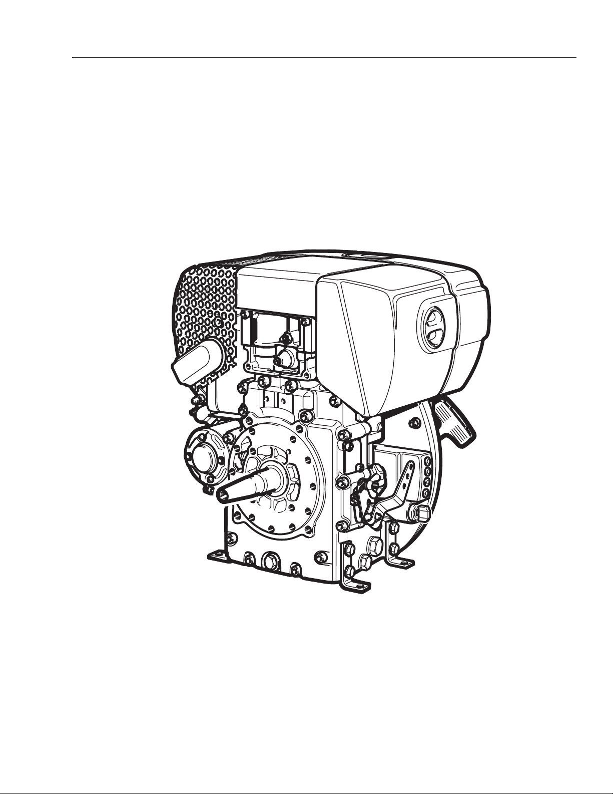
3.7 HATZ ENGINE
TYPE: HATZ 1B40
SECTION 3 - CHASSIS & TURNTABLE
3121623 – JLG Lift – 3-69

SECTION 3 - CHASSIS & TURNTABLE
2
8910
9
11
12
13
14
15
16
17
18
19
20
21
3
4
6
5
7
1 22
DESCRIPTION OF THE ENGINE
1. Type plate
2. Cylinder head cover
3. Exhaust silencer
4. Exhaust mesh insert
5. Oil pressure switch
6. Starter motor
7. Voltage regulator
8. Crankshaft - power take-off
9. Oil drain plug
10. Speed adjustment lever
11. Oil filter
12. Engine mountings
13. Ignition key
14. LED display
15. Intake opening for cooling and combustion air
16. Oil filler pipe and dipstick
17. Recoil starter
18. Engine shutdown pin
19. Dry-type air cleaner
20. Lifting lug
21. Fuel tank cap
22. Noise insulating hood
3-70 – JLG Lift – 3121623

GENERAL NOTES
Te c h n i c a l d a t a
Typ e 1B40
Design Air-cooled four-stroke diesel engine
Combustion system Direct injection
Number of cylinders 1
Bore / stroke mm 88 / 76
Displacement cm3 462
Lubricating oil capacity without oil sump with oil
sump
Difference between “max” and “min” levels without
oil sump with oil sump
Lubricating oil consumption (after running in) max. 1% of fuel consumption
Lubricating oil pressure (oil temperature 100 °C) approx. 2.5 bars at 3000 r.p.m.
Direction of rotation, power take-off end anti-clockwise
Valve clearance 10 - 30 °C
Inlet and exhaust valve
Max. tilt angle in operation, in direction Flywheel 25° down 3) all other directions
Weight (incl. fuel tank, air-cleaner, exhaust
silencer, recoil starter and electric starter)
Battery capacity Amp/h max. 12 V / 60 Amp/h
SECTION 3 - CHASSIS & TURNTABLE
l, approx.
l, approx.
l, approx.
l, approx.
mm 0.10
or automatically 2)
35°3)
kg,
approx.
1.5 1)
3.2 1)
0.8 1)
2.2 1)
at full load
55
1)
These values are intended as an approximate guide.
Themax.marking on the dipstick is the deter-mining factor.
2)
Depending on model (see maintenance charts).
3)
Exceeding these limits causes engine breakdown.
Tightening torques
Item Nm
Oil drain plug 50
3121623 – JLG Lift – 3-71

SECTION 3 - CHASSIS & TURNTABLE
MOTORENFABRIK HAT Z KG
D-94099 RUHSTORF
GMBH
CO
+
GMBH
CO
+
TYP
KENNZ.
MOTOR / FABRIK NO.
ABE / AUSF.
MIN NH PVCM
MADE IN GERMANY
-1
3
GMBH
CO
+
TYPE PLATE
The type plate is placed on the noise insulating hood and
includes the following engine information:
1. engine type
2. code (only for special equipment)
3. engine number (also stamped on crankcase)
4. max. engine speed
For any offer as well as spare parts orders it is necessary
to mention these data (also see spare parts list).
Engine serial number on crankcase
3-72 – JLG Lift – 3121623
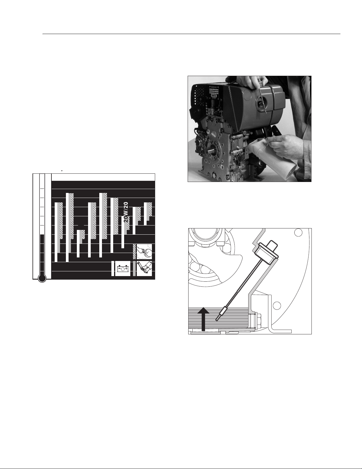
SECTION 3 - CHASSIS & TURNTABLE
y
-40
-30
-20
-10
0
10
20
30
40
50
10 4
86
68
50
32
14
-4
-22
-40
OIL: SAE...
°C°F
5W/30
5W/40
10W/40
10W/30
15W/40
30
40
122
10 W
max.
OPERATION
ENGINE OIL
Oil quality
Qualified are all trademark oils which fulfil at least one of
the following specifications:
ACEA – B2 / E2 or more significant
API – CD / CE / CF / CF-4 / CG-4or more significant.
If engine oil of a poorer quality is used, reduce oil change
intervals to 150 hours of operation.
Oil viscosity
When adding oil or checking the oil level, the engine must
be horizontal.
Remove oil filler screw and add engine oil.
Lubricating oil capacity: see Chapter Technical data.
Select the viscosity class according to the ambient temperature for cold starts.
3121623 – JLG Lift – 3-73
To check the oil level, remove the dipstick, clean it - then
screw it back in and finally remove it again.
Check the oil level on the dipstick and, if necessary, top
up to the max.level.

SECTION 3 - CHASSIS & TURNTABLE
gp
Set speed adjustment lever „1“either to 1/2START or max.
START position, as desired or necessary.
Starting at a lower speed will help to prevent exhaust
smoke.
– Grip the handle with both hands.
Recoil starter (down to –6 °C)
For starting preparations.
Starting procedure
– Pull the starting cable out by the handle until you feel a
slight resistance.
– Let the cable run back; in this way the entire length of
the starting cable can be used to start the engine.
– Devices which are not securely fastened should be
restrained with the foot.
Commence pulling the starting cable vigorously and at an
increasing speed (do not jerk it violently) until the engine
starts.
NOTE: If after several attempts of starting the exhaust begins to
emit white smoke, move the speed adjustment lever to the
STOP position and pull the starting cable out slowly 5
times. Repeat the starting procedure.
Electric starter
3-74 – JLG Lift – 3121623

SECTION 3 - CHASSIS & TURNTABLE
– For starting preparations.
– Insert the key to its stop and turn it to position I.
Depending upon the model, the battery charge telltale „2“
and the oil pressure warning light „3“will come on.
The engine temperature display „4“(additionalequipment)
lights up if the temperature at the cylinder head becomes
too high.
Switch off the engine and trace and eliminate the
cause of the problem.
– Turn the key to position II.
– Release the key as soon as the engine runs. The starting
key must spring back to position I and remain there dur-
ing engine operation.
– The battery charge and oil pressure lights should extinguish directly after the engine starts. The display lamp „1“
lights up to show that the engine is running.
– Prior to starting up again, the key has to be returned to
position 0. When the engine is running the starter repeat
lock in the ignition switch will prevent the starter from
engaging and suffering damage.
(additional equipment)
As soon as the starting key is at Position I, fuel shut-off
valve „1“is electrically released.
The fuel feed to the injection pump is then open and the
engine is ready to start.
When the engine is running, turning the starting key to
position 0 closes the cut-off valve and interrupts the fuel
supply to the injection pump, so that the engine stops.
This shut-off valve is also used for the automatic electrical
shutdown system.
Emergency start
If the shut-off valve is blocking the fuel supply as a result
of an electrical fault and the engine therefore cannot be
started, an emergency start can be attempted.
Proceed as follows for this:
Preheat er system (optional extra)
When starting a cold engine, the preheat indica-tor „5“will
light.
– Start the engine immediately after the light goes out.
Fuel shut-off valve, stop solenoid
3121623 – JLG Lift – 3-75

SECTION 3 - CHASSIS & TURNTABLE
– For emergency starting, turn the lever at fuel shut-off
solenoid „1“anti-clockwise by at least 90° using suitable
pliers. The lead seal wire will break off.
– As soon as the emergency start lever is in the starting
position, the electric starter or recoil starter can be used.
The oil level must always be checked before an emergency start, as insufficient oil pressure can lead to complete damage of the engine within a very short time.
AFTER THIS, THE ENGINE CAN ONLY BE STOPPED WITH THE
STARTING KEY IN THE EMERGENCY OPERATING MODE IF THE
EMERGENCY STARTING LEVER IS FIRST TURNED BACK CLOCKWISE TO THE STOP POSITION.
Immediately after a period of emergency running, ascertain the cause of the fault and have it rectified. Have the
emergency-starting lever sealed once again by a HATZ
service point.
When the automatic electrical shutdown system is used,
the emergency start described above means that liability
for risks must be accepted by the operator (Motorenfab-
rik HATZ assumes no liability).
In case of difficulty contact the nearest HATZ service
point.
Stopping the engine
Speed adjuster, standard version
– Move the speed adjustment lever „1“back to the STOP
position. The engine cuts out.
NOTE: Engines with a fixed lower idling speed cannot be
switched off using the speed adjustment lever. See the
paragraph entitled „Other ways of switching off the
engine“.
Automatic electrical shutdown system
Model with error memory
This is characterized by a brief flashing of all pilot lamps
once the starter key has been turned to position I.
Important!
If the engine cuts out immediately after starting or
switches off by itself during operation, a monitoring element in the automatic shutdown system has tripped. The
corresponding indicator light will come on. After the
engine has stopped, the display continues to glow for
about 12 seconds. The electrical device then switches
itself off automatically. The display lights up again after the
start key has been turned back to position 0 and then to
position I again.
Trace and eliminate the cause of the operating fault
before trying to restart the engine.
The display light goes out when the engine is next started.
On new or reconditioned engines, after the first 25
operating hours, always:
– Change engine oil.
– Check valve clearances and adjust if necessary.
– Examine screw connections. Do not tighten the cylin-
der head fastening.
If the engine is not used frequently, change the engine
oil after 12 months at the latest, regard-less of the actual
number of hours it has been inn operation.
3-76 – JLG Lift – 3121623
 Loading...