


Service and Maintenance Manual
Model
450A
450AJ
3120869
February 16, 2000


INTRODUCTION
SECTION A. INTRODUCTION - MAINTENANCE SAFETY
PRECAUTIONS
A GENERAL
This section contains the general safety precautions
which must be observed during maintenance of the aerial
platform. It is of utmost importance that maintenance personnel pay strict attention to these warnings and precautions to avoid possible injury to themselves or others, or
damage to the equipment. A maintenance program must
be followed to ensure that the machine is safe to operate.
MODIFICATION OF THE MACHINE WITHOUT CERTIFICATION BY
A RESPONSIBLE AUTHORITY THAT THE MACHINE IS AT LEAST
AS SAFE AS ORIGINALLY MANUFACTURED, IS A SAFETY VIOLATION.
The specific precautions to be observed during maintenance are inserted at the appropriate point in the manual.
These precautions are, for the most part, those that apply
when servicing hydraulic and larger machine component
parts.
Your safety, and that of others, is the first consideration
when engaging in the maintenance of equipment. Always
be conscious of weight. Never attempt to move heavy
parts without the aid of a mechanical device. Do not allow
heavy objects to rest in an unstable position. When raising
a portion of the equipment, ensure that adequate support
is provided.
SINCE THE MACHINE MANUFACTURER HAS NO DIRECT CONTROL OVER THE FIELD INSPECTION AND MAINTENANCE,
SAFETY IN THIS AREA RESPONSIBILITY OF THE OWNER/OPERATOR.
B HYDRAULIC SYSTEM SAFETY
It should be noted that the machines hydraulic systems
operate at extremely high potentially dangerous pressures. Every effort should be made to relieve any system
pressure prior to disconnecting or removing any portion of
the system.
C MAINTENANCE
FAILURE TO COMPLY WITH SAFETY PRECAUTIONS LISTED IN
THIS SECTION MAY RESULT IN MACHINE DAMAGE, PERSONNEL
INJURY OR DEATH AND IS A SAFETY VIOLATION.
• NO SMOKING IS MANDATORY. NEVER REFUEL DURING ELECTRICAL STORMS. ENSURE THAT FUEL
CAP IS CLOSED AND SECU RE AT ALL OTHER
TIMES.
• REMOVE ALL RINGS, WATCHES AND JEWELRY
WHEN PERFORMING ANY MAINTENANCE.
• DO NOT WEAR LONG HAIR UNRESTRAINED, OR
LOOSE-FITTING CLOTHING AND NECKTIES WHICH
ARE APT TO BECOME CAUGHT ON OR ENTANGLED
IN EQUIPMENT.
• OBSERVE AND OBEY ALL WARNINGS AND CAUTIONS ON MACHINE AND IN SERVICEMANUAL.
• KEEP OIL, GREASE, WATER, ETC. WIPED FROM
STANDING SURFACES AND HAND HOLDS.
• USE CAUTION WHEN CHECKING A HOT, PRESSURIZED COOLANT SYSTEM.
• NEVER WORK UNDER AN ELEVATED BOOM UNTIL
BOOM HAS BEEN SA FELY RESTRAINED FROM ANY
MOVEMENT BY BLOCKING OR OVERHEAD SLING,
OR BOOM SAFETY PROP HAS BEEN ENGAGED.
• BEFORE MAKING ADJUSTMENTS, LUBRICATING OR
PERFORMING ANY OTHER MAINTENANCE, SHUT
OFF ALL POWER CONTROLS.
• BATTERY SHOULD ALWAYS BE DISCONNECTEDDURING REPLACEMENT OF ELECTRICAL COMPONENTS.
• KEEP ALL SUPPORT EQUIPMENT AND ATTACHMENTS STOWED IN THEIR PROPER PLACE.
• USE ONLY APPROVED, NONFLAMMABLE CLEANING
SOLVENTS.
Relieve system pressure by cycling the applicable control
several times with the engine stopped and ignition on, to
direct any line pressure back into the reservoir. Pressure
feed lines to system components can then be disconnected with minimal fluid loss.
3120869 – JLG Lift – A-1

INTRODUCTION
REVISON LOG
May, 1998 - Original Issue
August 5, 1999 - Revised
2-54 thru 2-57 - Updated 10-12-99
2-59 - Updated 10-12-99
1-4 thru 1-6 - Updated 11-1-99
2-26 - Updated 11-1-99
1-2 and 1-3 - Updated 2-16-00
2-59 thru 2-62 - Updated 2-16-00
A-2 – JLG Lift – 3120869

TABLE OF CONTENTS
TABLE OF CONTENTS
SUBJECT - SECTION, PARAGRAPH PAGE NO.
SECTION A - INTRODUCTION - MAINTENANCE SAFETY PRECAUTIONS
A General . . . . . . . . . . . . . . . . . . . . . . . . . . . . . . . . . . . . . . . . . . . . . . . . . . . . . . . . . . . . . . . . . . . . . .A-1
B Hydraulic System Safety. . . . . . . . . . . . . . . . . . . . . . . . . . . . . . . . . . . . . . . . . . . . . . . . . . . . . . . . .A-1
C Maintenance . . . . . . . . . . . . . . . . . . . . . . . . . . . . . . . . . . . . . . . . . . . . . . . . . . . . . . . . . . . . . . . . . .A-1
SECTION 1 - SPECIFICATIONS
1.1 Capacities . . . . . . . . . . . . . . . . . . . . . . . . . . . . . . . . . . . . . . . . . . . . . . . . . . . . . . . . . . . . . . . . . . . .1-1
1.2 Component Data. . . . . . . . . . . . . . . . . . . . . . . . . . . . . . . . . . . . . . . . . . . . . . . . . . . . . . . . . . . . . . .1-1
1.3 Tires . . . . . . . . . . . . . . . . . . . . . . . . . . . . . . . . . . . . . . . . . . . . . . . . . . . . . . . . . . . . . . . . . . . . . . . . .1-1
1.4 Specifications and Performance Data. . . . . . . . . . . . . . . . . . . . . . . . . . . . . . . . . . . . . . . . . . . . . . .1-1
1.5 Torque Requirements . . . . . . . . . . . . . . . . . . . . . . . . . . . . . . . . . . . . . . . . . . . . . . . . . . . . . . . . . . .1-2
1.6 Lubrication . . . . . . . . . . . . . . . . . . . . . . . . . . . . . . . . . . . . . . . . . . . . . . . . . . . . . . . . . . . . . . . . . . . .1-2
1.7 Pressure Settings - PSI (Bar). . . . . . . . . . . . . . . . . . . . . . . . . . . . . . . . . . . . . . . . . . . . . . . . . . . . . .1-3
1.8 Major Component Weights . . . . . . . . . . . . . . . . . . . . . . . . . . . . . . . . . . . . . . . . . . . . . . . . . . . . . . .1-3
1.9 Critical Stability Weights . . . . . . . . . . . . . . . . . . . . . . . . . . . . . . . . . . . . . . . . . . . . . . . . . . . . . . . . .1-3
1.10 Cylinder Specifications . . . . . . . . . . . . . . . . . . . . . . . . . . . . . . . . . . . . . . . . . . . . . . . . . . . . . . . . . .1-3
1.11 Function Speeds (in Seconds) . . . . . . . . . . . . . . . . . . . . . . . . . . . . . . . . . . . . . . . . . . . . . . . . . . . .1-7
1.12 Serial Number Location. . . . . . . . . . . . . . . . . . . . . . . . . . . . . . . . . . . . . . . . . . . . . . . . . . . . . . . . . .1-7
SECTION 2 - PROCEDURES
2.1 General . . . . . . . . . . . . . . . . . . . . . . . . . . . . . . . . . . . . . . . . . . . . . . . . . . . . . . . . . . . . . . . . . . . . . .2-1
2.2 Service and Guidelines . . . . . . . . . . . . . . . . . . . . . . . . . . . . . . . . . . . . . . . . . . . . . . . . . . . . . . . . . .2-1
2.3 Lubrication and Information . . . . . . . . . . . . . . . . . . . . . . . . . . . . . . . . . . . . . . . . . . . . . . . . . . . . . .2-2
2.4 Cylinders - Theory of Operation . . . . . . . . . . . . . . . . . . . . . . . . . . . . . . . . . . . . . . . . . . . . . . . . . . .2-3
2.5 Valves - Theory of Operation. . . . . . . . . . . . . . . . . . . . . . . . . . . . . . . . . . . . . . . . . . . . . . . . . . . . . .2-4
2.6 Boom Maintenance . . . . . . . . . . . . . . . . . . . . . . . . . . . . . . . . . . . . . . . . . . . . . . . . . . . . . . . . . . . . .2-4
2.7 Drift Test . . . . . . . . . . . . . . . . . . . . . . . . . . . . . . . . . . . . . . . . . . . . . . . . . . . . . . . . . . . . . . . . . . . . .2-7
2.8 Cylinder Checking Procedure. . . . . . . . . . . . . . . . . . . . . . . . . . . . . . . . . . . . . . . . . . . . . . . . . . . . .2-8
2.9 Cylinder Repair . . . . . . . . . . . . . . . . . . . . . . . . . . . . . . . . . . . . . . . . . . . . . . . . . . . . . . . . . . . . . . . .2-9
2.10 Mid and Lower Lift Cylinder Bleeding Procedure. . . . . . . . . . . . . . . . . . . . . . . . . . . . . . . . . . . . . .2-16
2.11 Hydraulic Pump (gear) . . . . . . . . . . . . . . . . . . . . . . . . . . . . . . . . . . . . . . . . . . . . . . . . . . . . . . . . . .2-16
2.12 Swing Bearing. . . . . . . . . . . . . . . . . . . . . . . . . . . . . . . . . . . . . . . . . . . . . . . . . . . . . . . . . . . . . . . . .2-23
2.13 Worm gear. . . . . . . . . . . . . . . . . . . . . . . . . . . . . . . . . . . . . . . . . . . . . . . . . . . . . . . . . . . . . . . . . . . .2-27
2.14 Boom Synchronizing Procedure. . . . . . . . . . . . . . . . . . . . . . . . . . . . . . . . . . . . . . . . . . . . . . . . . . .2-27
2.15 Extend-A-Reach. . . . . . . . . . . . . . . . . . . . . . . . . . . . . . . . . . . . . . . . . . . . . . . . . . . . . . . . . . . . . . . .2-28
2.16 Adjustment Procedure For Lockout Valve . . . . . . . . . . . . . . . . . . . . . . . . . . . . . . . . . . . . . . . . . . .2-28
2.17 Torque Hub (Prior to S/N 39594) . . . . . . . . . . . . . . . . . . . . . . . . . . . . . . . . . . . . . . . . . . . . . . . . . .2-29
2.18 Torque Hub (S/N 39594 to Present) . . . . . . . . . . . . . . . . . . . . . . . . . . . . . . . . . . . . . . . . . . . . . . . .2-34
2.19 Drive Brake (Ausco) . . . . . . . . . . . . . . . . . . . . . . . . . . . . . . . . . . . . . . . . . . . . . . . . . . . . . . . . . . . .2-45
2.20 Boom Limit Switches. . . . . . . . . . . . . . . . . . . . . . . . . . . . . . . . . . . . . . . . . . . . . . . . . . . . . . . . . . . .2-48
2.21 Lift Up and Platform Level Down Disable Switch . . . . . . . . . . . . . . . . . . . . . . . . . . . . . . . . . . . . . .2-48
2.22 Throttle Checks and Adjustments - Deutz Engine . . . . . . . . . . . . . . . . . . . . . . . . . . . . . . . . . . . . .2-49
2.23 Drive and Steer Controller. . . . . . . . . . . . . . . . . . . . . . . . . . . . . . . . . . . . . . . . . . . . . . . . . . . . . . . .2-51
2.24 Lift and Swing Controller. . . . . . . . . . . . . . . . . . . . . . . . . . . . . . . . . . . . . . . . . . . . . . . . . . . . . . . . .2-53
2.25 Function Control . . . . . . . . . . . . . . . . . . . . . . . . . . . . . . . . . . . . . . . . . . . . . . . . . . . . . . . . . . . . . . .2-53
2.26 Tilt Alarm Switch . . . . . . . . . . . . . . . . . . . . . . . . . . . . . . . . . . . . . . . . . . . . . . . . . . . . . . . . . . . . . . .2-55
2.27 Pressure Setting Procedures . . . . . . . . . . . . . . . . . . . . . . . . . . . . . . . . . . . . . . . . . . . . . . . . . . . . .2-55
2.28 Hydraulic Component Start-Up Procedures and Recommendations . . . . . . . . . . . . . . . . . . . . . .2-59
2.29 Semi-Track . . . . . . . . . . . . . . . . . . . . . . . . . . . . . . . . . . . . . . . . . . . . . . . . . . . . . . . . . . . . . . . . . . .2-61
2.30 Preventive Maintenance and Inspection Schedule. . . . . . . . . . . . . . . . . . . . . . . . . . . . . . . . . . . . .2-63
3120869 – JLG Lift – i

TABLE OF CONTENTS
TABLE OF CONTENTS (continued)
SUBJECT - SECTION, PARAGRAPH PAGE NO.
SECTION 3 - TROUBLESHOOTING
3.1 General . . . . . . . . . . . . . . . . . . . . . . . . . . . . . . . . . . . . . . . . . . . . . . . . . . . . . . . . . . . . . . . . . . . . . . 3-1
3.2 Troubleshooting . . . . . . . . . . . . . . . . . . . . . . . . . . . . . . . . . . . . . . . . . . . . . . . . . . . . . . . . . . . . . . . 3-1
3.3 Hydraulic Circuit Checks. . . . . . . . . . . . . . . . . . . . . . . . . . . . . . . . . . . . . . . . . . . . . . . . . . . . . . . . . 3-1
LIST OF FIGURES
FIGURE NO. TITLE PAGE NO.
1-1. Lubrication Diagram . . . . . . . . . . . . . . . . . . . . . . . . . . . . . . . . . . . . . . . . . . . . . . . . . . . . . . . . . . . .1-4
1-2. Serial Number Locations. . . . . . . . . . . . . . . . . . . . . . . . . . . . . . . . . . . . . . . . . . . . . . . . . . . . . . . . . 1-7
1-3. Torque Chart . . . . . . . . . . . . . . . . . . . . . . . . . . . . . . . . . . . . . . . . . . . . . . . . . . . . . . . . . . . . . . . . . .1-8
2-1. Location of Components - Boom Removal. . . . . . . . . . . . . . . . . . . . . . . . . . . . . . . . . . . . . . . . . . .2-4
2-2. Location of Components - Removal of Telescope Cylinder. . . . . . . . . . . . . . . . . . . . . . . . . . . . . .2-5
2-3. Location of Components - Front Wear Pads . . . . . . . . . . . . . . . . . . . . . . . . . . . . . . . . . . . . . . . . .2-6
2-4. Boom Prop Configuration . . . . . . . . . . . . . . . . . . . . . . . . . . . . . . . . . . . . . . . . . . . . . . . . . . . . . . . .2-10
2-5. Cylinder Barrel Support. . . . . . . . . . . . . . . . . . . . . . . . . . . . . . . . . . . . . . . . . . . . . . . . . . . . . . . . . . 2-11
2-6. Capscrew Removal . . . . . . . . . . . . . . . . . . . . . . . . . . . . . . . . . . . . . . . . . . . . . . . . . . . . . . . . . . . . .2-11
2-7. Cylinder Rod Support . . . . . . . . . . . . . . . . . . . . . . . . . . . . . . . . . . . . . . . . . . . . . . . . . . . . . . . . . . .2-11
2-8. Tapered Bushing Removal . . . . . . . . . . . . . . . . . . . . . . . . . . . . . . . . . . . . . . . . . . . . . . . . . . . . . . .2-12
2-9. Gar-Max Bearing Installation. . . . . . . . . . . . . . . . . . . . . . . . . . . . . . . . . . . . . . . . . . . . . . . . . . . . . .2-12
2-10. Rod Seal Installation . . . . . . . . . . . . . . . . . . . . . . . . . . . . . . . . . . . . . . . . . . . . . . . . . . . . . . . . . . . .2-13
2-11. Wiper Seal Installation. . . . . . . . . . . . . . . . . . . . . . . . . . . . . . . . . . . . . . . . . . . . . . . . . . . . . . . . . . .2-13
2-12. Installation of Head Seal Kit . . . . . . . . . . . . . . . . . . . . . . . . . . . . . . . . . . . . . . . . . . . . . . . . . . . . . . 2-13
2-13. Piston Seal Kit Installation. . . . . . . . . . . . . . . . . . . . . . . . . . . . . . . . . . . . . . . . . . . . . . . . . . . . . . . .2-14
2-14. Tapered Bushing Installation . . . . . . . . . . . . . . . . . . . . . . . . . . . . . . . . . . . . . . . . . . . . . . . . . . . . .2-14
2-15. Seating the Tapered Bearing . . . . . . . . . . . . . . . . . . . . . . . . . . . . . . . . . . . . . . . . . . . . . . . . . . . . .2-15
2-16. Poly-Pak Piston Seal Installation. . . . . . . . . . . . . . . . . . . . . . . . . . . . . . . . . . . . . . . . . . . . . . . . . . .2-15
2-17. Rod Assembly Installation. . . . . . . . . . . . . . . . . . . . . . . . . . . . . . . . . . . . . . . . . . . . . . . . . . . . . . . .2-15
2-19. Swing Bearing Feeler Gauge Check. . . . . . . . . . . . . . . . . . . . . . . . . . . . . . . . . . . . . . . . . . . . . . . .2-23
2-18. Swing Bearing Installation. . . . . . . . . . . . . . . . . . . . . . . . . . . . . . . . . . . . . . . . . . . . . . . . . . . . . . . .2-24
2-20. Swing Bearing Tolerance Measuring Point . . . . . . . . . . . . . . . . . . . . . . . . . . . . . . . . . . . . . . . . . .2-25
2-21. Swing Bearing Torquing Sequence . . . . . . . . . . . . . . . . . . . . . . . . . . . . . . . . . . . . . . . . . . . . . . . .2-26
2-22. Synchronizing Valve . . . . . . . . . . . . . . . . . . . . . . . . . . . . . . . . . . . . . . . . . . . . . . . . . . . . . . . . . . . .2-27
2-23. Extend-A-Reach. . . . . . . . . . . . . . . . . . . . . . . . . . . . . . . . . . . . . . . . . . . . . . . . . . . . . . . . . . . . . . . . 2-28
2-24. Front Axle . . . . . . . . . . . . . . . . . . . . . . . . . . . . . . . . . . . . . . . . . . . . . . . . . . . . . . . . . . . . . . . . . . . .2-29
2-25. Ring Gear/Cover . . . . . . . . . . . . . . . . . . . . . . . . . . . . . . . . . . . . . . . . . . . . . . . . . . . . . . . . . . . . . . .2-29
2-26. Carrier . . . . . . . . . . . . . . . . . . . . . . . . . . . . . . . . . . . . . . . . . . . . . . . . . . . . . . . . . . . . . . . . . . . . . . . 2-30
2-27. Torque Hub (Prior to S/N 39594) - Exploded View. . . . . . . . . . . . . . . . . . . . . . . . . . . . . . . . . . . . .2-31
2-28. Torque Hub (Prior to S/N 39594) - Cutaway View . . . . . . . . . . . . . . . . . . . . . . . . . . . . . . . . . . . . .2-32
2-29. Torque Hub (S/N 39594 to Present) - Cutaway View . . . . . . . . . . . . . . . . . . . . . . . . . . . . . . . . . . .2-35
2-30. Cluster Gear Punch Marks . . . . . . . . . . . . . . . . . . . . . . . . . . . . . . . . . . . . . . . . . . . . . . . . . . . . . . .2-43
2-31. Drive Brake (Ausco) . . . . . . . . . . . . . . . . . . . . . . . . . . . . . . . . . . . . . . . . . . . . . . . . . . . . . . . . . . . .2-46
2-32. Switch Adjustment. . . . . . . . . . . . . . . . . . . . . . . . . . . . . . . . . . . . . . . . . . . . . . . . . . . . . . . . . . . . . .2-48
2-33. Functional Check . . . . . . . . . . . . . . . . . . . . . . . . . . . . . . . . . . . . . . . . . . . . . . . . . . . . . . . . . . . . . .2-48
2-34. Addco Adjustments - Deutz . . . . . . . . . . . . . . . . . . . . . . . . . . . . . . . . . . . . . . . . . . . . . . . . . . . . . .2-49
2-35. Drive and Steer Adjustment . . . . . . . . . . . . . . . . . . . . . . . . . . . . . . . . . . . . . . . . . . . . . . . . . . . . . .2-52
2-36. Lift and Swing Adjustment . . . . . . . . . . . . . . . . . . . . . . . . . . . . . . . . . . . . . . . . . . . . . . . . . . . . . . . 2-53
2-37. Function Control Card Adjustment. . . . . . . . . . . . . . . . . . . . . . . . . . . . . . . . . . . . . . . . . . . . . . . . .2-54
2-38. Tilt Switch Adjustment . . . . . . . . . . . . . . . . . . . . . . . . . . . . . . . . . . . . . . . . . . . . . . . . . . . . . . . . . . .2-55
2-39. Main Valve (Proportional Controls) - Sheet 1 . . . . . . . . . . . . . . . . . . . . . . . . . . . . . . . . . . . . . . . . .2-56
2-40. Main Valve (Proportional Controls) - Sheet 2 . . . . . . . . . . . . . . . . . . . . . . . . . . . . . . . . . . . . . . . . .2-57
2-41. Valve Location - Chassis. . . . . . . . . . . . . . . . . . . . . . . . . . . . . . . . . . . . . . . . . . . . . . . . . . . . . . . . .2-58
ii – JLG Lift – 3120869

TABLE OF CONTENTS
LIST OF FIGURES (continued)
FIGURE NO. TITLE PAGE NO.
3-1. Electrical Components Installation - Sheet 1 . . . . . . . . . . . . . . . . . . . . . . . . . . . . . . . . . . . . . . . . .3-20
3-2. Electrical Components Installation - Sheet 2 . . . . . . . . . . . . . . . . . . . . . . . . . . . . . . . . . . . . . . . . .3-21
3-3. Electrical Schematic - Boom, Turntable, Chassis - Deutz - Sheet 1 . . . . . . . . . . . . . . . . . . . . . . .3-22
3-4. Electrical Schematic - Boom, Turntable, Chassis - Deutz - Sheet 2 . . . . . . . . . . . . . . . . . . . . . . .3-23
3-5. Electrical Schematic - Platform -Deutz - Sheet 1 . . . . . . . . . . . . . . . . . . . . . . . . . . . . . . . . . . . . . .3-24
3-6. Electrical Schematic - Platform -Deutz - Sheet 2 . . . . . . . . . . . . . . . . . . . . . . . . . . . . . . . . . . . . . .3-25
3-7. Hydraulic Schematic - Proportional Controls . . . . . . . . . . . . . . . . . . . . . . . . . . . . . . . . . . . . . . . . .3-26
LIST OF TABLES
TABLE NO. TITLE PAGE NO.
1-1 Torque Requirements . . . . . . . . . . . . . . . . . . . . . . . . . . . . . . . . . . . . . . . . . . . . . . . . . . . . . . . . . . .1-2
1-2 Hydraulic Oil . . . . . . . . . . . . . . . . . . . . . . . . . . . . . . . . . . . . . . . . . . . . . . . . . . . . . . . . . . . . . . . . . .1-2
1-3 Lubrication Specifications. . . . . . . . . . . . . . . . . . . . . . . . . . . . . . . . . . . . . . . . . . . . . . . . . . . . . . . .1-2
1-4 Mobil EAL Envirosyn H 46 Specs . . . . . . . . . . . . . . . . . . . . . . . . . . . . . . . . . . . . . . . . . . . . . . . . .1-2
1-5 Major Component Weights . . . . . . . . . . . . . . . . . . . . . . . . . . . . . . . . . . . . . . . . . . . . . . . . . . . . . . .1-3
1-6 Critical Stability Weights . . . . . . . . . . . . . . . . . . . . . . . . . . . . . . . . . . . . . . . . . . . . . . . . . . . . . . . . .1-3
1-7 Cylinder Specifications . . . . . . . . . . . . . . . . . . . . . . . . . . . . . . . . . . . . . . . . . . . . . . . . . . . . . . . . . .1-3
1-8 Lubrication Chart. . . . . . . . . . . . . . . . . . . . . . . . . . . . . . . . . . . . . . . . . . . . . . . . . . . . . . . . . . . . . . .1-5
2-1 Cylinder Head and Tapered Bushing Torque Specifications. . . . . . . . . . . . . . . . . . . . . . . . . . . . .2-16
2-2 Holding Valve Torque Specification . . . . . . . . . . . . . . . . . . . . . . . . . . . . . . . . . . . . . . . . . . . . . . . .2-16
2-3 Hydraulic Pump Bolt Torque Chart. . . . . . . . . . . . . . . . . . . . . . . . . . . . . . . . . . . . . . . . . . . . . . . . .2-22
2-4 Position Controller Truth Table . . . . . . . . . . . . . . . . . . . . . . . . . . . . . . . . . . . . . . . . . . . . . . . . . . . .2-49
2-5 Adjustment Chart. . . . . . . . . . . . . . . . . . . . . . . . . . . . . . . . . . . . . . . . . . . . . . . . . . . . . . . . . . . . . . .2-62
2-6 Preventive Maintenance and Inspection Schedule. . . . . . . . . . . . . . . . . . . . . . . . . . . . . . . . . . . . .2-64
3-1 Platform Assembly - Troubleshooting. . . . . . . . . . . . . . . . . . . . . . . . . . . . . . . . . . . . . . . . . . . . . . . 3-2
3-2 Boom Assembly - Troubleshooting . . . . . . . . . . . . . . . . . . . . . . . . . . . . . . . . . . . . . . . . . . . . . . . .3-3
3-3 Turntable Assembly - Troubleshooting. . . . . . . . . . . . . . . . . . . . . . . . . . . . . . . . . . . . . . . . . . . . . .3-8
3-4 Chassis Assembly - Troubleshooting . . . . . . . . . . . . . . . . . . . . . . . . . . . . . . . . . . . . . . . . . . . . . . .3-9
3-5 Hydraulic System - Troubleshooting. . . . . . . . . . . . . . . . . . . . . . . . . . . . . . . . . . . . . . . . . . . . . . . .3-15
3-6 Electrical System - Troubleshooting. . . . . . . . . . . . . . . . . . . . . . . . . . . . . . . . . . . . . . . . . . . . . . . .3-18
3120869 – JLG Lift – iii

TABLE OF CONTENTS
This Page Left Blank Intentionally.
iv – JLG Lift – 3120869

SECTION 1 - SPECIFICATIONS
SECTION 1. SPECIFICATIONS
1.1 CAPACITIES
Fuel Tank - 62.5 liters
Hydraulic Oil Tank - 106 liters
Torque Hub - 0.5 liters
NOTE: Torque hubs should be one half full of lubricant.
Engine Crankcase (Ford LRG425) - 4.5 L
Engine Crankcase (Deutz F3M1011F) - 6 L
1.2 COMPONENT DATA
Engine - Deutz F3M1011F
Fuel - Diesel
No. of Cylinders - 3
BHP at Max. RPM - 48
RPM Setting (No Load) - Mid - 1500
1.3 TIRES
12x16.5
1.4 SPECIFICATIONS AND PERFORMANCE
DATA
Max. Platform Height - 13.8 M
Max. Horizontal Reach - 7.3 M
Unrestricted Rated Capacity - 230kg
Maximum Capacity - 230 kg
Maximum Tire Load (450A) - 3230 kg
Maximum Tire Load (450AJ) - 3357 kg
Overall Width - 1.98 m
Tai lsw in g - Z ero
Stowed Height - 2.24 m
Stowed Length - 6.15 m
Wheelbase - 1.98 m
Ground Clearance - 28 cm
Platforms - 0.76m x 1.22M
0.76m x 1.52M
0.76m x 1.83M
Rated Gradeability - 2WD -30%
4WD - 40%
• Pneumatic - 6 Bar
•Weight: 58 kg
12x16.5
• Fo am-Filled
• Weight: 149 kg
33/1550x16.5
• Pneumatic - 6 Bar
•Weight: 61 kg
33/1550x16.5
• Fo am-Filled
• Weight: 179 kg
33/16LL x 16.1
• Pneumatic - 3 bar
• Weight: 41.5 kg
33/16LL x 16.1
• Foam-Filled
• Weight: 193 kg
System Voltage - 12 Volts
Max. Hydraulic System Operating Pressure - 207 bar
Travel Speed (2WD) - 7.2 kph
Travel Speed (4WD) - 3.6 mph
Ground Bearing Pressure (450A)
12x16.5 pneu. - 3.23 kg/cm
12x16.5 FF - 3.93 kg/cm
33/1550x16.5 pneu. - 2.46 kg/cm
33/1550x16.5 FF - 3.51 kg/cm
Ground Bearing Pressure (450AJ)
12x16.5 pneu. - 3.37 kg/cm
12x16.5 FF - 4.07 kg/cm
33/1550x16.5 pneu. - 2.53 kg/cm
33/1550x16.5 FF - 3.65 kg/cm
2
2
2
2
2
2
2
2
3120869 – JLG Lift – 1-1

SECTION 1 - SPECIFICATIONS
1.5 TORQUE REQUIREMENTS
wear and rust protection characteristics as mineral oils,
but will not adversely affect ground water or the environment when spilled or leaked in small amounts. Mobil
Table 1-1.Torque Requirements
Description Torque Value Interval Hours
Wheel Lugs 170 ft. lbs.
Semi-Track
Wheel Lugs
Swing Bearing
(Dry)
Swing Bearing
((Loctite)
(231 Nm)
90 ft. lbs.
(122 Nm)
220 ft. lbs.
(298 Nm)
240 ft. lbs.
(326 Nm)
150
150
50/600*
50/600*
EAL224H has a viscosity of 34 cST at 40° C and a viscosity
index of 213. The operating range of this oil is -18° C to
+83° C.
IT IS RECOMMENDED THAT MOBIL EAL224H HYDRAULIC OIL BE
STORED ABOVE FREEZING (0° C) AS THE OIL MAY APPEAR
CLOUDY AFTER EXPOSURE TO LOW TEMPERATURES FOR
EXTENDED PERIODS OF TIME. THE CLOUDINESS WILL DISAPPEAR
WHEN THE OIL IS WARMED TO AT LEAST 10° C AND AGITATED. DO
NOT ATTEMPT TO "THIN" THE OIL WITH NO.2 DIESEL FUEL. FOR
BEST RESULTS, STORE THE OIL ABOVE FREEZING.
* Check swing bearing bolts for security after first 50
hours of operation and every 600 hours thereafter.
NOTE: Accidentally mixing Mobil EAL224 H hydraulic oi l with
other mineral oils will cause no loss of performance
characteristics. However, biodegradability may be
1.6 LUBRICATION
Hydraulic Oil
Table 1-2.Hydraulic Oil
Hydraulic System
Operating
Temperature Range
+0° to + 18 0° F
(-18° to +83 ° C)
+0° to + 21 0° F
(-18° to +99 ° C)
+50° to + 2 10° F
(+10° to + 99° C
NOTE: Hydraulic oils must have anti-wear qualities at least
to API Service Classification GL-3, and sufficient
S.A.E. Viscosity
Grade
10W
10W-20, 10W30
20W-20
reduced and toxicity may be increased, depending
on the oil and level of contamination.
Lubrication Specifications
Table 1-3.Lubrication Specifications.
KEY SPECIFICATIONS
MPG Multipurpos e Grease having a minimum d ripping point of 350
degrees F. Excellent water resistance and adhesive qualities; and
being of extreme p ressure type (Timken OK 40 po unds minimum).
EPGL Extreme Pressu re Gear Lube (oil) meeting API Se r-
vice Classification GL-5 or Mil-Spec Mil-L-2105.
HO Hydraulic Oil. API Service Classification GL-3, SAE
10W-20, Viscosity Index 152, e.g. Kendall Hyken 052.
EO Engine (crankcase) Oil. Gas - API SF/SG class, MIL-L-
2104. Diesel - API CC/CD class, MIL-L-2104B/MIL-L2104C.
chemical stability for mobile hydraulic system service. JLG Industries recommends Mobilfluid 424
hydraulic oil, which has an SAE viscosity index of
152.
NOTE: When temperatures remain consistently below 20
degrees F. (-7 degrees C.), JLG Industries recommends the use of Mobil DTE11.
Aside from JLG recommendations, it is not advisable to
mix oils of different brands or types, as they may not contain the same required additives or be of comparable viscosities. If use of hydraulic oil other than Mobilfluid 424 is
desired, contact JLG Industries for proper recommendations.
Some machines may be specially equipped with Mobil
EAL224H biodegradable and non-toxic hydraulic oil. This
oil is vegetable oil based and possesses the same anti-
Updated 2-16-00
NOTE: Refer to Lubrication Chart for spe cific lubricatio n pr o-
cedures..
Table 1-4. Mobil EAL Envirosyn H 46 Specs
Type Synthetic Biodegradable
ISO Viscosity Grade 46
Specific Gravity .910
Pour Point, Max -44° F (-44° C)
Flash Point, Min. 500° F (260° C)
Weight
Viscosity
at 40° C 45 cSt
at 100° C 8.0 cSt
Viscosity In dex 153
7.64 lb. per gal.
(0.9 kg per liter)
1-2 – JLG Lift – 3120869

SECTION 1 - SPECIFICATIONS
1.7 PRESSURE SETTINGS - PSI (BAR)
Main Relief
Main Relief - 3000 (207)
Lift Up - 3000 (207) - Governed by Main Relief
Lift Down - 2500 (172) - Governed by Level Down Relief
Level Down - 2500 (172)
Level Up - 2500 (172)
Swing (Right & Left) - 1750 (121)
Drive
Drive - Pre-Set 4500 (310)
1.8 MAJOR COMPONENT WEIGHTS
Table 1-5.Major Component Weights
Component LB. KG.
6 ft Platform 160 73
5 ft. Platform 145 66
4 ft. Platform 130 59
Extend-A-Reach 230 104
Upper Boom (450A) 985 447
Upper Boom (450A J) 1250 567
Upper Upright 212 96
Tower Boom 515 234
Lower Upright 100 45
Tower Link 150 68
Turntable 3560 1615
Engine Tray 890 404
Hydraulic Tray 225 102
Tail Counterweight 3410 1547
Bolt-on T/T Cwt. ( AJ) 487 221
Chassis (12x16.5 pneu. t ires) 4200 1905
12x16.5 pneu. Tire & Wheel 130 59
12x16.5 F/F Tire & Wheel 305 138
33/15.5x16.5 pneu. Tire & Wheel 150 68
33/15.5x16.5 F/F Tire & Whee l 374 170
33/16LL x 16.1 pneu Tire & Wheel 91.5 41.5
33/16LL x 16.1 F/F Tire & Wheel 426 193.4
1.9 CRITICAL STABILITY WEIGHTS
Table 1-6.Critical Stability Weights
Component LB. KG.
Ford Engine 339 154
Deutz Engine 441 200
Isuzu Engine 389 176
6 ft Platform 160 73
5 ft. Platform 145 66
4 ft. Platform 130 59
Bolt-on T/T Cwt. (AJ) 487 221
12x16.5 pneu. Tire & Wheel 130 59
12x16.5 F/F Tire & Wheel 305 138
33/15.5x16.5 pneu. Tire & Wh eel 150 68
33/15.5x16.5 F/F Tire & Whee l 374 170
33/16LL x 16.1 pneu Tire & Wheel 91.5 41.5
33/16LL x 16.1 F/F Tire & Wheel 426 193.4
1.10 CYLINDER SPECIFICATIONS
Table 1-7.Cylinder Specifications
Cylinder Bore Stroke Rod Dia.
Oscillation 2.5 in.
(63.5 mm)
Lower Lift 4.5 in.
(114.3 mm)
Mid Lift 4. 0 in.
(101.6 mm)
Upper Lift 3.5 in.
(88.9 mm)
Telescope 2 in.
(50.8 mm)
Level 4.0 in.
(101.6 mm)
Jib 3.0 in.
(76.2 mm)
Rotate 1. 5 in.
(38.1 mm)
4.125 in.
(104.8 mm)
21.5 in.
(546.1 mm)
18.8 in.
(479.5 mm)
24.4 in.
(619.4 mm)
83.75 in.
(2127.25 mm)
10.9 in.
(277.5 mm)
18.4 in.
(467.4 mm)
9.3 in.
(236.2 mm)
(44.45 mm)
(63.5 mm)
(50.8 mm)
(63.5 mm)
(31.75 mm)
(31.75 mm)
(38.1 mm)
1.75 in.
2.5 in.
2.0 in.
2.5 in.
1.25 in.
1.25 in.
1.5 in.
0.75 in.
(19 mm)
Updated 2-16-00
3120869 – JLG Lift – 1-3

SECTION 1 - SPECIFICATIONS
Figure 1-1. Lubrication Diagram
Updated 11-1-99
1-4 – JLG Lift – 3120869

Components
Lubrication
Swing Bearing - Internal
1
Ball Bearing
Swing Bearing - Teeth
2a
End Bearings - Worm
2b
Gear*
Wheel Bearings (2WD
3
Only)
Wheel Drive Hub
4
Hydraulic Return Filter
5
Hydraulic Charge Filter
6
Hydraulic Oil
7
Suction Strainer s (In Tank)
8
Steer Cylinder
9
Oscillation Cylinders
10
SECTION 1 - SPECIFICATIONS
Table 1-8. Lubrication Chart
Interval Hours
Number/Type
Lube Points
2 Grease Fitt ing A/R MPG X
Spray On A/R OGL X More frequent lubrication intervals may be
2 A/R MPG X Remove grease fittings and install plugs after
Repack A/R MPG X
Level/Fill Plug 0.5 liters (1/2 full) EPGL X Change after first 150 hours then every 1200
N/A N/A N/A X Change after first 50 hours and every 300
N/A N/A N/A X Change after first 50 hours and every 300
F il l C a p 116 li t er s Tan k
2 N/A N/A X Remove and clean at time of hydraulic oil
4A/RMPGX
2A/RMPGX
Capacity Lube
124 liters System
3
Months
150 hrs
6
Months
300 hrs
1 Year
600 hrs
2 Years
1200 hrs
required.
greasing.
hours of operation.
hours thereafter or as indicated by condition
indicator.
hours thereafter or as indicated by condition
indicator.
HO X Check level daily.
Change every 1200 hours.
change.
Comments
Engines
Oil Change w/Filter - Ford
11
Oil Change w/Filter - Deutz
12
Oil Change w/Filter - Isuzu
13
Fuel Filter - Ford
14
Fill Cap/Spin-on
Element
Fill Cap/Spin-on
Element
Fill Cap/Spin-on
Element
Replaceable
5 Quarts (4 .7 L) EO X Check leve l daily; change every 150 hour s.
Adjust fina l oil level by m ark on dipstick .
6 liters crankcase
**4. 5 liters cooler
5.6 liters crankcase
6.1 liters w/ cooler
EO X Check level da ily; change eve ry 600 hours.
Adjust fina l oil level by m ark on dipstick .
EO X Check level da ily; change eve ry 150 hours.
Adjust fina l oil level by m ark on dipstick .
N/A N/A X
Element
15
16
Fuel Filter - Deutz
Fuel Filter - Isuzu
Replaceable
Element
Replaceable
N/A N/A X
N/A N/A X
Element
17
Air Filter - Ford
Replaceable
N/A N/A X Or as indicated by condition indicator
Element
Updated 11-1-99
3120869 – JLG Lift – 1-5

SECTION 1 - SPECIFICATIONS
Table 1-8. Lubrication Chart
Interval Hours
Components
Air Filter - Deut z
18
Air Filter - Isuzu
19
NOTES: KEY TO LUBRICANTS
Lubrication intervals are based on machine operation under normal conditions. For machines used in multi shift operations and/or exposed to hostile environments or conditions, lubrication frequencies must be increased accordingly.
* If necessary install grease fittings into worm gear housing and grease bearings.
DO NOT OVERGREASE BEARINGS. OVERGREASING BEARINGS WILL RESULT IN
BLOWING OUTER SEAL IN HOUSING.
**When changing oil in the Deutz oil cooled engine, drain both the crankcase and the cooler. When refilling it is acceptable to overfill crankcase (10.5 L),
capacity of both crankcase and cooler combined). Start engine, allow the engine to run until the thermostat opens (approximately 105 degrees C) cooler will
fill up within minutes; shut down and wait for approximately two minutes. Check oil level, fill oil to max marking on dipstick.
Number/Type
Lube Points
Replaceable
Element
Replaceable
Element
Capacity Lube
N/A N/A X Or as indicated by condition indicator
N/A N/A X Or as indicated by condition indicator
3
Months
150 hrs
6
Months
300 hrs
1 Year
600 hrs
2 Years
1200 hrs
EO
EPGL
HO
MPG
OGL
Engine Oil
Extreme Pressure Gear Lube
Hydraulic Fluid (Mobil DTE-11M)
Multi-Purpose Grease
Open Gear Lubricant - Mobiltac 375 or
equivalent
Comments
Updated 11-1-99
1-6 – JLG Lift – 3120869

SECTION 1 - SPECIFICATIONS
1.11 FUNCTION SPEEDS (IN SECONDS)
450A
Main Boom Lift Up - 22-38
Main Boom Lift Down - 12-24
Tele In - 12-24
Tele Out - 20-32
Swing - 85-110
Rotate (Left & Right) - 16-25
450AJ
Main Boom Lift Up - 22-38
Main Boom Lift Down - 12-24
Tele In - 9-20
Tele Out - 14-30
Swing - 85-110
Rotate (Left & Right) - 16-25
E-A-R Up - 9-24
E-A-R Down - 12-24
1.12 SERIAL NUMBER LOCATION
A serial number plate is affixed to the left rear side of the
frame. If the serial number plate is damaged or missing,
the machine serial number is stamped on the left side of
the frame.
xxxxxxx
SERIAL NUMBER
PLATE
SERIAL NUMBER
STAMPEDON FRAME
Figure 1-2. Serial Number Locations
3120869 – JLG Lift – 1-7

SECTION 1 - SPECIFICATIONS
NM
TORQUE
(as received)
UNPLATED
CAP SCREWS
UNBRAKO 1960 SERIES
WITH LOC-WEL PATCH
SOCKET HEAD CAP SCREW
CLAMP LOAD
)
(LOCTITE
242 OR 271
262)
(LOCTITE
(LUB.)
TORQUE
(KG)
NM
NM
NM
2
4
4
5
1
1
2
6
18
19
1442
1651
18
12
14
21
34
37
2377
2631
41
41
30
34
25
27
61
68
3493
3983
68
75
54
61
48
48
95
102
4822
5384
122
109
85
95
81
75
149
156
6437
7253
183
163
130
146
122
109
210
224
8256
9208
224
258
188
209
149
176
285
298
10251
11612
326
359
244
277
231
244
495
542
15150
16919
570
631
408
456
380
434
793
861
20956
23088
895
983
658
724
624
678
1173
1241
27488
30074
1492
1342
931
1079
922
1003
1681
1871
34610
38828
1898
2136
1396
1566
1464
1302
2373
2549
43954
48671
2712
2983
1970
2183
1844
2034
3145
3308
52391
59648
3559
4068
2586
2935
2413
2766
4122
4433
63731
71669
4712
5322
3430
3856
3200
3607
SAE GRADE 8
SAE GRADE 5
VALUES FOR ZINC PLATED BOLTS ONLY
(DRY OR
SAE GRADE 8 BOLTS & GRADE 8 NUTS
CLAMP
(LOCTITE
(LOCTITE
TORQUE
(DRY OR
SAE GRADE 5 BOLTS & GRADE 2 NUTS
CLAMP
AREA
STRESS
THREAD
DIA.
BOLT
NM
LOC. 263)
(KG)
LOAD
)
NM
242 OR 271
262)
NM
NM
(LUB.)
NM
LOC. 263)
(KG)
LOAD
(SQ. CM)
(CM)
2
2
245
272
1
1
1
1
172
191
0.0153
0.0168
0.2845
3
3
372
417
2
2
2
2
263
277
0.0232
0.0258
0.3505
5
5
572
599
3
3
4
4
408
426
0.0356
0.0374
0.4166
7
8
717
817
4
4
6
5
508
583
0.0445
0.0508
0.4826
16
19
1297
1488
16
12
9
10
11
14
916
1052
0.0808
0.0925
0.6350
34
34
2141
2821
29
26
22
23
19
18
26
23
1515
1678
0.1473
0.1331
0.7938
61
68
3175
3583
54
48
38
43
34
31
48
41
2241
2540
0.2230
0.1969
0.9525
95
109
4332
4854
81
75
68
61
68
48
68
75
3085
3425
0.3015
0.2700
1.1112
149
163
5783
6532
115
136
92
108
75
88
102
122
4105
4854
0.4061
0.3604
1.2700
204
231
7539
8278
163
183
133
148
109
122
149
163
5874
5262
0.5156
0.4623
1.4288
298
326
9231
10433
224
258
183
207
149
176
204
231
7394
6532
0.6502
0.5740
1.5875
515
570
15241
13653
387
448
325
363
271
298
353
407
9662
10796
0.9474
0.8484
1.9050
814
895
18870
20775
644
705
523
576
434
475
583
637
14697
13336
1.2929
1.1735
2.2225
1220
1356
23360
27080
915
997
785
858
651
719
868
949
19142
17509
1.6840
1.5392
2.5400
1736
1953
31162
34927
968
1087
814 1139
895 1254
1085
1193
21546
19187
2.1742
1.9380
2.8575
2468
2712
38554
43818
1593
1762
1368
1516
1139
1247
1519
1681
27035
24404
2.7254
2.4613
3.1750
3227
3688
47174
53570
2068
2373
1792
2042
1492
1708
1980
2278
29076
33113
2.9337
3.3401
3.4925
4284
4827
57380
142200
2746
3118
2379
2676
1980
2630
35381
3.5687
4.0132 39781 2983 2224
3.8100
Figure 1-3. Torque Chart
9
8
7
7
6
THD
SIZE
40
48
40
36
32
28
18
16
14
13
12
11
32
32
24
20
24
24
20
20
8
6
4
10
1/4
5/16
3/8
7/16
1/2
9/16
18
5/8
18
10
3/4
16
7/8
14
12
12
1
1-1/8
1-1/4
12
12
1-1/2
6
1-1/2
12
Note: These torque values do not apply to cadium plated fasteners.
1-8 – JLG Lift – 3120869

SECTION 2. PROCEDURES
SECTION 2 - PROCEDURES
2.1 GENERAL
This section provides information necessary to perform
maintenance on the aerial platform. Descriptions, techniques and specific procedures are designed to provide
the safest and most efficient maintenance for use by personnel responsible for ensuring the correct installation
and operation of machine components and systems.
WHEN AN ABNORMAL CONDITION IS NOTED AND PROCEDURES
CONTAINED HEREIN DO NOT SPECIFICALLY RELATE TO THE
NOTED IRREGULARITY, WORK SHOULD BE STOPPED AND
TECHNICALLY QUALIFIED GUIDANCE OBTAINED BEFORE WORK
IS RESUMED.
The maintenance procedures included consist of servicing and component removal and installation, disassembly
and assembly, inspection, lubrication and cleaning. Information on any special tools or test equipment is also provided where applicable.
2.2 SERVICE AND GUIDELINES
General
The following information is provided to assist you in the
use and application of servicing and maintenance procedures contained in this chapter.
Safety and Workmanship
Your safety, and that of others, is the first consideration
when engaging in the maintenance of equipment. Always
be conscious of weight. Never attempt to move heavy
parts without the aid of a mechanical device. Do not allow
heavy objects to rest in an unstable position. When raising
a portion of the equipment, ensure that adequate support
is provided.
nent is disconnected, cap or cover all openings to
prevent entry of foreign matter.
3. Clean and inspect all parts during servicing or maintenance, and assure that all passages and openings
are unobstructed. Cover all parts to keep them
clean. Be sure all parts are clean before they are
installed. New parts should remain in their containers until they are ready to be used.
Components Removal and Installation
1. Use adjustable lifting devices, whenever possible, if
mechanical assistance is required. All slings (chains,
cables, etc.) should be parallel to each other and as
near perpendicular as possible to top of part being
lifted.
2. Should it be necessary to remove a component on
an angle, keep in mind that the capacity of an eyebolt or similar bracket lessens, as the angle between
the supporting structure and the component
becomes less than 90 degrees.
3. If a part resists removal, check to see whether all
nuts, bolts, cables, brackets, wiring, etc., have been
removed and that no adjacent parts are interfering.
Component Disassembly and Reassembly
When disassembling or reassembling a component, complete the procedural steps in sequence. Do not partially
disassemble or assemble one part, then start on another.
Always recheck your work to assure that nothing has been
overlooked. Do not make any adjustments, other than
those recommended, without obtaining proper approval.
Pressure-Fit Parts
When assembling pressure-fit parts, use an anti-seize or
molybdenum disulfide base compound to lubricate the
mating surface.
Cleanliness
1. The most important single item in preserving the
long service life of a machine is to keep dirt and foreign materials out of the vital components. Precautions have been taken to safeguard against this.
Shields, covers, seals, and filters are provided to
keep air, fuel, and oil supplies clean; however, these
items must be maintained on a scheduled basis in
order to function properly.
2. At any time when air, fuel, or oil lines are disconnected, clear adjacent areas as well as the openings
and fittings themselves. As soon as a line or compo-
3120869 – JLG Lift – 2-1

SECTION 2 - PROCEDURES
Bearings
1. When a bearing is removed, cover it to keep out dirt
and abrasives. Clean bearings in nonflammable
cleaning solvent and allow to drip dry. Compressed
air can be used but do not spin the bearing.
2. Discard bearings if the races and balls (or rollers)
are pitted, scored, or burned.
3. If bearing is found to be serviceable, apply a light
coat of oil and wrap it in clean (waxed) paper. Do not
unwrap reusable or new bearings until they are
ready to install.
4. Lubricate new or used serviceable bearings before
installation. When pressing a bearing into a retainer
or bore, apply pressure to the outer race. If the bearing is to be installed on a shaft, apply pressure to the
inner race.
Gaskets
Check that holes in gaskets align with openings in the
mating parts. If it becomes necessary to hand-fabricate a
gasket, use gasket material or stock of equivalent material
and thickness. Be sure to cut holes in the right location, as
blank gaskets can cause serious system damage.
Bolt Usage and Torque Application
Hydraulic System
1. Keep the system clean. If evidence of metal or rubber particles are found in the hydraulic system, drain
and flush the entire system.
2. Disassemble and reassemble parts on clean work
surface. Clean all metal parts with non-flammable
cleaning solvent. Lubricate components, as
required, to aid assembly.
Lubrication
Service applicable components with the amount, type,
and grade of lubricant recommended in this manual, at
the specified intervals. When recommended lubricants are
not available, consult your local supplier for an equivalent
that meets or exceeds the specifications listed.
Battery
Clean battery, using a non-metallic brush and a solution of
baking soda and water. Rinse with clean water. After
cleaning, thoroughly dry battery and coat terminals with
an anti corrosion compound.
Lubrication and Servicing
Components and assemblies requiring lubrication and
servicing are shown in the Lubrication Chart in Section 1.
1. Use bolts of proper length. A bolt which is too long
will bottom before the head is tight against its related
part. If a bolt is too short, there will not be enough
thread area to engage and hold the part properly.
When replacing bolts, use only those having the
same specifications of the original, or one which is
equivalent.
2. Unless specific torque requirements are given within
the text, standard torque values should be used on
heat-treated bolts, studs, and steel nuts, in accordance with recommended shop practices. (See
Torque Chart Section 1.)
Hydraulic Lines and Electrical Wiring
Clearly mark or tag hydraulic lines and electrical wiring, as
well as their receptacles, when disconnecting or removing
them from the unit. This will assure that they are correctly
reinstalled.
2.3 LUBRICATION AND INFORMATION
Hydraulic System
1. The primary enemy of a hydraulic system is contamination. Contaminants enter the system by various
means, e.g., using inadequate hydraulic oil, allowing
moisture, grease, filings, sealing components, sand,
etc., to enter when performing maintenance, or by
permitting the pump to cavitate due to insufficient
system warm-up or leaks in the pump supply (suction) lines.
2. The design and manufacturing tolerances of the
component working parts are very close, therefore,
even the smallest amount of dirt or foreign matter
entering a system can cause wear or damage to the
components and generally results in faulty operation. Every precaution must be taken to keep
hydraulic oil clean, including reserve oil in storage.
Hydraulic system filters should be checked,
cleaned, and/or replaced as necessary, at the specified intervals required in the Lubrication Chart in
Section 1. Always examine filters for evidence of
metal particles.
2-2 – JLG Lift – 3120869

SECTION 2 - PROCEDURES
3. Cloudy oils indicate a high moisture content which
permits organic growth, resulting in oxidation or corrosion. If this condition occurs, the system must be
drained, flushed, and refilled with clean oil.
4. It is not advisable to mix oils of different brands or
types, as they may not contain the same required
additives or be of comparable viscosities. Good
grade mineral oils, with viscosities suited to the
ambient temperatures in which the machine is operating, are recommended for use.
NOTE: Metal particles may appear in the oil or filters of new
machines due to the wear-in of meshing components.
Hydraulic Oil
1. Refer to Section 1 for recommendations for viscosity
ranges.
2. JLG recommends Mobilfluid 424 hydraulic oil, which
has an SAE viscosity of 10W-30 and a viscosity
index of 152.
NOTE: Start-up of hydraulic system with oil temperatures
below -26 de grees C (- 15 degrees F ) is not recommended. If it is necessary to start the system in a
sub-zero environment, it will be necessary to heat
the oil with a low density, 100VAC heater to a minimum temperature of -26 degrees C (-15 degrees F).
3. The only exception to the above is to drain and fill
the system with Mobil DTE 11 oil or its equivalent.
This will allow start up at temperatures down to -29
degrees C (-20 degrees F). However, use of this oil
will give poor performance at temperatures above49
degrees C (120 degrees F). Systems using DTE 11
oil should not be operated at temperatures above 94
degrees C (200 degrees F) under any condition.
Changing Hydraulic Oil
1. Use of any of the recommended crankcase or
hydraulic oils eliminates the need for changing the
oil on a regular basis. However, filter elements must
be changed after the first 50 hours of operation and
every 300 hours thereafter. If it is necessary to
change the oil, use only those oils meeting or
exceeding the specifications appearing in this manual. If unable to obtain the same type of oil supplied
with the machine, consult local supplier for assistance in selecting the proper equivalent. Avoid mixing petroleum and synthetic base oils. JLG
Industries recommends changing the hydraulic oil
annually.
nants from the service container. Always clean the
mesh element of the filter and replace the cartridge
any time the system oil is changed.
3. While the unit is shut down, a good preventive maintenance measure is to make a thorough inspection
of all hydraulic components, lines, fittings, etc., as
well as a functional check of each system, before
placing the machine back in service.
Lubrication Specifications
Specified lubricants, as recommended by the component
manufacturers, are always the best choice, however,
multi-purpose greases usually have the qualities which
meet a variety of single purpose grease requirements.
Should any question arise, regarding the use of greases in
maintenance stock, consult your local supplier for evaluation. Refer to Section 1 for an explanation of the lubricant
key designations appearing in the Lubrication Chart.
2.4 CYLINDERS - THEORY OF OPERATION
Systems Incorporating Double Acting
Cylinders
Cylinders are of the double acting type. Systems incorporating double acting cylinders are as follows: Slave Level,
Master Level, Lift, Telescope, Axle Lockout and Steer. A
double acting cylinder is one that requires oil flow to operate the cylinder rod in both directions. Directing oil (by
actuating the corresponding control valve to the piston
side of the cylinder) forces the piston to travel toward the
rod end of the barrel, extending the cylinder rod (piston
attached to rod). When the oil flow is stopped, movement
of rod will stop. By directing oil to the rod side of the cylinder, the piston will be forced in the opposite direction and
the cylinder rod will retract.
Systems Incorporating Holding Valves
Holding valves are used in the - Lift, Telescope, Lockout,
and Slave Level circuits to prevent retraction of the cylinder rod should a hydraulic line rupture or a leak develop
between the cylinder and its related control valve.
2. Use every precaution to keep the hydraulic oil clean.
If the oil must be poured from the original container
into another, be sure to clean all possible contami-
3120869 – JLG Lift – 2-3
SECTION 2 - PROCEDURES
2.5 VALVES - THEORY OF OPERATION
Solenoid Control Valve
Control valves used are four-way three-position solenoid
valves of the sliding spool design. When a circuit is activated and the control valve solenoid energizes, the spool
is shifted and the corresponding work port opens to permit oil flow to the component in the selected circuit with
the opposite work port opening to reservoir. Once the circuit is deactivated (control returned to neutral) the valve
spool returns to neutral (center) and oil flow is then
directed through the valve body and returns to reservoir. A
typical control valve consist of the valve body, sliding
spool, and two solenoid assemblies. The spool is
machine fitted in the bore of the valve body. Lands on the
spool divide the bore into various chambers, which, when
the spool is shifted, align with corresponding ports in the
valve body open to common flow. At the same time other
ports would be blocked to flow. The spool is spring loaded
to center position, therefore when the control is released,
the spool automatically returns to neutral, prohibiting any
flow through the circuit.
Relief Valves
Relief valves are installed at various points within the
hydraulic system to protect associated systems and components against excessive pressure. Excessive pressure
can be developed when a cylinder reaches its limit of
travel and the flow of pressurized fluid continues from the
system control. The relief valve provides an alternate path
for the continuing flow from the pump, thus preventing
rupture of the cylinder, hydraulic line or fitting. Complete
failure of the system pump is also avoided by relieving circuit pressure. The relief valve is installed in the circuit
between the pump outlet (pressure line) and the cylinder
of the circuit, generally as an integral part of the system
valve bank. Relief pressures are set slightly higher than
the load requirement, with the valve diverting excess
pump delivery back to the reservoir when operating pressure of the component is reached.
2.6 BOOM MAINTENANCE
IF PERFORMING MAINTENANCE ON THE BOOM, DO NOT USE A
LIFTING DEVICE TO LIFT THE BOOMS UNLESS THE HOLDING
VALVES HAVE BEEN REMOVED FIRST. FAILURE TO DO SO WILL
RESULT IN SEVERE DAMAGE TO THE BOOM.
Removal of the Boom Assembly
1. Remove the platform and platform support as follows:
a. Disconnect electrical cable from control con-
sole.
b. Tag and disconnect the hydraulic lines running
to the rotate cylinders. Cap the hydraulic lines
and ports.
c. Using an overhead crane or suitable lifting
device, use nylon support straps to support the
platform/support.
NOTE: When removing the retaining pin from the rod end of
the level cylinder, make sure the cylinder is properly
supported.
d. Remove bolts and keeper pins that secures the
retaining pins. Using a suitable brass drift and
hammer, remove the retaining pins from the platform support.
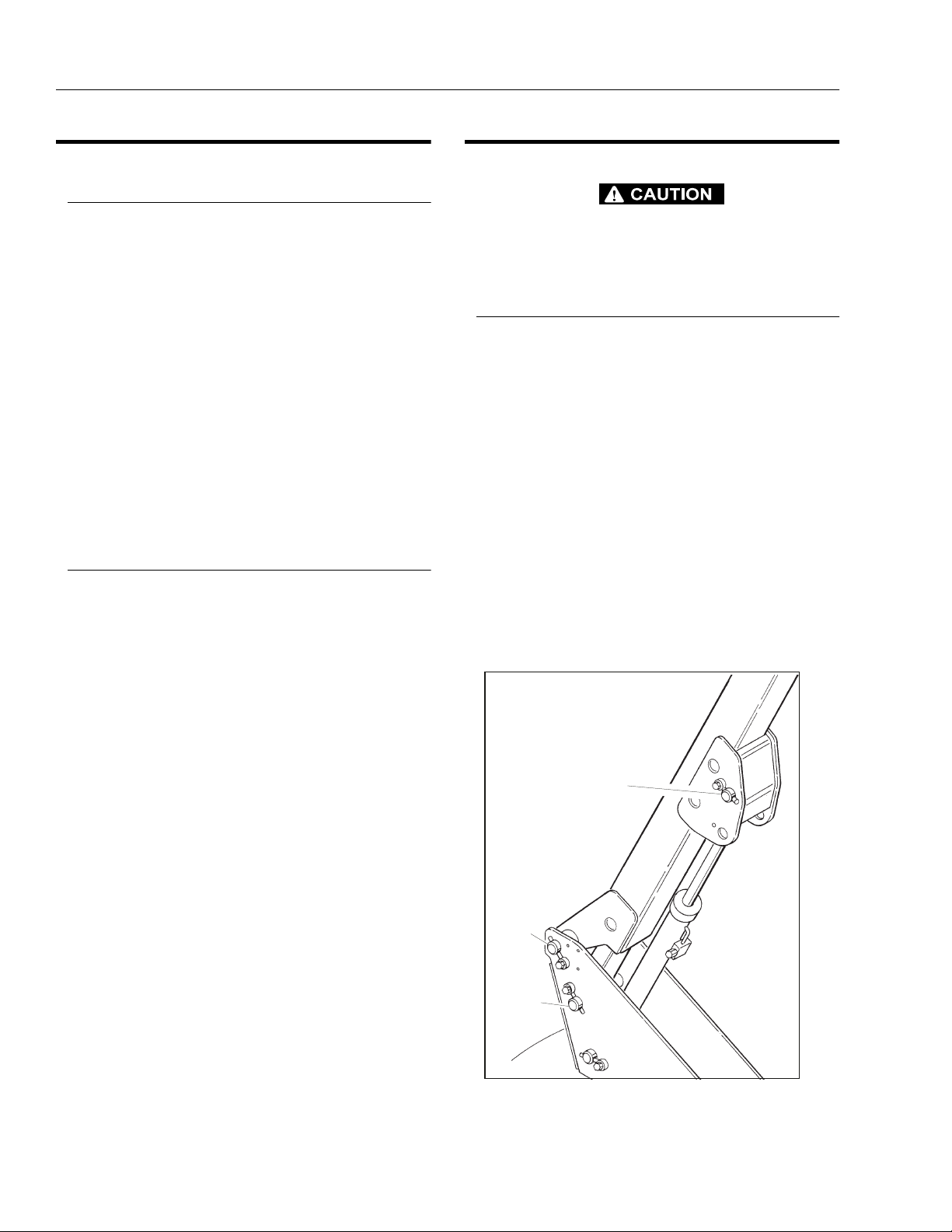
LIFT CYLINDER
PIVOT PIN
BOOM
PIVOT
LEVEL
LINK
PIVOT
Figure 2-1. Location of Components - Boom Removal
2-4 – JLG Lift – 3120869

SECTION 2 - PROCEDURES
2. Remove the boom from the turntable as follows:
a. Disconnect wiring harness from ground control
harness connector.
HYDRAULIC LINES AND PORTS SHOULD BE CAPPED IMMEDIATELY AFTER DISCONNECTING LINES TO AVOID ENTRY OF
CONTAMINANTS INTO SYSTEM.
b. Tag and disconnect hydraulic lines from boom
to control valve. Use a suitable container to
retain any residual hydraulic fluid. Cap all
hydraulic lines and ports.
c. Using a suitable lifting equipment, adequately
support boom weight along entire length.
d. Remove the bolts and keeper pins securing the
lift cylinder pivot pin. Using a suitable brass drift
and hammer, remove the pivot pin from the
lower boom.
NOTE: To gain access for removal of the pivot pins, it may
be necessary to remove the ground control box,
hydraulic and fuel tanks, and the counterweight.
e. Remove hardware securing the level link pivot
pin. Using a suitable brass drift and hammer,
remove the pin from the level link and turntable.
f. Remove hardware securing the lower boom
pivot pin. Using a suitable brass drift and hammer, remove pin from the turntable.
g. Using all applicable safety precautions, carefully
lift boom assembly clear of turntable and lower
to ground or suitable supported work surface.
Disassembly of the Main Boom
1. Loosen jam nuts on aft end of fly boom wear pad
adjustment and loosen adjustments.
2. Using a portable power source, attach hose to telescope cylinder port block. Using all applicable
safety precautions, activate hydraulic system and
extend cylinder to gain access to cylinder rod retaining pin. Shut down hydraulic system.
3. Carefully disconnect hydraulic hose from retract port
of cylinder. There will be initial weeping of hydraulic
fluid which can be caught in a suitable container.
After initial discharge, there should be no further
leakage from the retract port.
4. Remove hardware securing telescope cylinder to
the fly boom section, then remove pin from fly.
5. Remove hardware securing telescope cylinder to
the base boom section.
WHEN REMOVING TELESCOPE CYLINDER FROM BOOM SECTIONS. CARE SHOULD BE TAKEN NOT TO LEAVE CYLINDER
REST ON POWERTRACK WHICH COULD CAUSE DAMAGE TO
POWERTRACK.
FLY BOOM
RETAINING RING
RETAINING RING
BASE BOOM
TELESCOPE CYLINDER
Figure 2-2. Location of Components - Removal of Telescope Cylinder
3120869 – JLG Lift – 2-5

SECTION 2 - PROCEDURES
Figure 2-3. Location of Components - Front Wear Pads
6. Using a suitable lifting device, remove telescope cylinder from boom sections.
7. Using a piece of tape, mark the length of hoses and
wires from front of fly boom and bottom of base
boom for reassembly.
8. Remove hardware securing the front wear pads on
base boom section, remove wear pads.
9. Remove hardware securing the powertrack to the aft
end of the fly boom section.
10. Using a suitable lifting device, remove fly boom from
boom section.
11. Remove hydraulic lines and electrical cables from
powertrack.
12. Remove hardware securing powertrack to the base
boom section. Remove powertrack.
Inspection
1. Inspect all boom pivot pins for wear, scoring or other
damage, and for tapering or ovality. Replace pins as
necessary.
2. Inspect lift cylinder pins for wear, scoring or other
damage, and for tapering or ovality. Ensure pin surfaces are protected prior to installation. Replace pins
as necessary.
3. Inspect telescope cylinder rod attach pin for wear,
scoring or other damage. Replace pin as necessary.
4. Inspect inner diameter of boom pivot bushings for
scoring, distortion, wear or other damage. Replace
bushings as necessary.
5. Inspect wear pads for wear.
6. Inspect all threaded components for damage such
as stretching, thread deformation, or twisting.
Replace as necessary.
7. Inspect structural units of boom assembly for bending, cracking, separation of welds, or other damage.
Replace boom sections as necessary.
Assembly of the Main Boom
1. Install power track to the attach point on the base
boom section. Secure power track with the attaching
hardware.
2. Install hydraulic lines and electrical cables into the
power track.
3. Install wear pads to the aft end of the fly section.
4. Using suitable lifting equipment, slide fly section into
the base section until power track attach point aligns
with holes in side of base section.
5. Attach the power track to the aft end of fly boom
section. Secure power track with the attaching hardware.
6. Using suitable lifting equipment, slide fly boom section out to gain access to telescope cylinder attach
pin hole.
7. Measure the distance between the telescope cylinder port block attach point on base boom section
and the attach point on fly boom section.
8. Connect a suitable auxiliary hydraulic power source
to the telescope cylinder port block.
9. Extend the telescope cylinder the distance of the
two attach points.
10. Secure the sling and lifting device at the telescope
cylinder’s approximate center of gravity, and lift the
cylinder to the aft end of the boom assembly.
WHEN INSERTING THE TELESCOPE CYLINDER INTO THE BOOM,
CARE MUST BE TAKEN NOT TO DAMAGE THE POWER TRACK
ASSEMBLY.
11. Slowly slide the telescope cylinder into boom
assembly, align rod end with attach point in fly section. Insert pin and secure with retaining ring.
12. Align bolt holes at aft end of base boom section with
telescope cylinder port block. Secure telescope cylinder with hardware.
2-6 – JLG Lift – 3120869
SECTION 2 - PROCEDURES
13. Install wear pads at end of base boom section.
Using shims, adjust the adjustable wear pads to
zero clearance. Adjust pads alternately side to side,
so that fly boom section is centered in base boom
section.
14. Retract boom section fully. Using shims, adjust wear
pads at aft end of boom section to zero clearance.
Adjust pads alternately side to side, so that fly boom
section is centered in base boom section.
15. Disconnect auxiliary power source from telescope
cylinder.
Installation of the Boom Assembly
1. Using suitable lifting equipment, position boom
assembly on turntable so that boom pivot holes in
both boom and turntable are aligned.
2. Install boom pivot pin, ensuring that location of the
hole in pivot pin aligns with attach point on upright.
3. Using all applicable safety precautions, operate lifting equipment in order to position boom lift cylinder
and level link so that holes in cylinder rod end and
level link are aligned with the one in the turntable.
Insert cylinder pins.
4. If necessary, gently tap pins into position with a soft
headed mallet, ensuring that attach holes in pins are
aligned with attach holes in boom structure. Secure
with hardware.
5. Connect all hosing and wiring.
6. Install the platform to the boom assembly.
7. Connect all hosing and wiring at platform control
station.
8. Using all safety precautions, operate machine systems and extend and retract boom for four or five
cycles.
9. Shut down machine systems and check for leakage.
2.7 DRIFT TEST
NOTE: It is recommended that the machine be shut down in
the test mode for at least one hour prior to beginning
the drift test. This will allow the oil temperature in the
cylinder to stabilize with the ambient temperature.
Thermal expansion or retraction of the hydraulic oil
can greatly affect cylinder movement.
Telescope Cylinder
NOTE: Switches referenced in this pro ce dur e are loc ated on
the Ground Control Panel.
1. Activate hydraulic system, properly set extendable
axles and position boom in stowed position; adhere
to all safety precautions.
BEFORE RAISING AND EXTENDING BOOM, ENSURE THAT
AREAS ABOVE AND BELOW BOOM AND PLATFORM AND AHEAD
OF PLATFORM ARE CLEAR OF ALL OBSTRUCTIONS AND PERSONNEL.
2. Position LIFT control switch to UP and hold until
boom reaches horizontal.
3. Position TELESCOPE control switch to OUT and
hold until boom extends approximately 1.2 meters
(4 feet); measure from end of base section to end of
mid section.
4. Position LIFT control switch to UP and hold until
boom reaches maximum elevation. Shut down
engine.
5. Tag and carefully disconnect the hydraulic lines to
the telescope cylinder at control valve.
6. Observe oil flow from cylinder lines. Oil leaking from
extend port hose indicates a leaking counterbalance
valve. Oil leaking from retract port hose indicates
leakage by cylinder piston.
7. Leave boom elevated in test position for approximately one hour.
BEFORE LOWERING BOOM, ENSURE THAT AREAS BELOW
BOOM AND PLATFORM ARE CLEAR OF ALL PERSONNEL AND
OBSTRUCTIONS.
3120869 – JLG Lift – 2-7

SECTION 2 - PROCEDURES
8. Position LIFT control switch to DOWN and hold until
boom reaches horizontal; check boom length
against measurement. If boom has retracted more
than 2.5 cm (1 inch) and oil is leaking around rodend of telescope cylinder (check with light and
inspection mirror), seals are defective and require
replacement, or cylinder rod is scored and cylinder
requires overhaul or replacement. If boom has
retracted and oil is leaking from counterbalance
valve, the valve is either improperly adjusted, or
defective and requires replacement.
9. Connect hydraulic lines to control valve.
Lift Cylinder
NOTE: Switches referenced in thi s p r oc edu re are lo ca ted on
the Ground Control Panel.
1. Activate hydraulic system, properly set extendable
axles and position boom in stowed position; adhere
to all safety precautions.
NOTE: Tape measure or cord should be at least 2 meters (6
feet) long for use in this test.
2. Attach tape measure or cord to bottom of platform.
BEFORE RAISING BOOM, ENSURE THAT AREAS ABOVE AND
BELOW BOOM AND PLATFORM ARE CLEAR OF ALL OBSTRUCTIONS AND PERSONNEL.
3. With boom fully retracted, place LIFT control switch
to UP and hold until platform is approximately 2
meters (6 feet) above ground level. Shut down
engine.
4. Tag and carefully disconnect hydraulic lines to lift
cylinder at control valve. Use a suitable container to
retain any residual hydraulic fluid.
5. Observe oil flow from cylinder lines. Oil leaking from
extend port hose indicates a leaking counterbalance
valve. Oil leaking from retract port hose indicates
leakage by cylinder piston.
6. Leave boom elevated in test position for approximately one (1) hour.
7. With tape measure or cord used for reference,
check to see whether boom has lowered (crept)
more than 7.5 cm (3 inches).
8. If boom has lowered and oil is leaking around rodend cap of cylinder, seals in cylinder are defective
and require replacement. If boom has lowered and
oil is leaking from the counterbalance valve, the
valve is either improperly adjusted or defective and
requires replacement.
ENSURE THAT HYDRAULIC LINES ARE CONNECTED AS
MARKED PRIOR TO BEING DISCONNECTED.
9. Connect hydraulic lines to control valve.
2.8 CYLINDER CHECKING PROCEDURE
IF PERFORMING MAINTENANCE ON THE BOOM CYLINDERS, DO
NOT USE A LIFTING DEVICE TO LIFT THE BOOMS UNLESS THE
HOLDING VALVES HAVE BEEN REMOVED FIRST. FAILURE TO DO
SO WILL RESULT IN SEVERE DAMAGE TO THE BOOM.
NOTE: Cylinder check must be performed anytime a system
component is replaced or when improper system
operation is suspected.
Cylinders Without Counterbalance Valves Master Cylinder and Steer Cylinder
1. Using all applicable safety precautions, activate
engine and fully extend cylinder to be checked. Shut
down engine.
2. Carefully disconnect hydraulic hoses from retract
port of cylinder. There will be some initial weeping of
hydraulic fluid which can be caught in a suitable
container. After the initial discharge, there should be
no further drainage from the retract port.
3. Activate engine and extend cylinder.
4. If cylinder retract port leakage is less than 6-8 drops
per minute, carefully reconnect hose to port and
retract cylinder. If leakage continues at a rate of 6-8
drops per minute or more, cylinder repair must be
made.
5. With cylinder fully retracted, shut down engine and
carefully disconnect hydraulic hose from cylinder
extend port.
6. Activate engine and retract cylinder. Check extend
port for leakage.
7. If extend port leakage is less than 6-8 drops per
minute, carefully reconnect hose to extend port,
than activate cylinder through one complete cycle
and check for leaks. If leakage continues at a rate of
6-8 drops per minute or more, cylinder repairs must
be made.
2-8 – JLG Lift – 3120869

SECTION 2 - PROCEDURES
Cylinders With Dual Counterbalance Valves Slave Level, Lift, and Telescope
OPERATE ALL FUNCTIONS FROM GROUND CONTROL STATION
ONLY.
1. Using all applicable safety precautions, activate
hydraulic system.
IF WORKING ON THE PLATFORM LEVEL CYLINDER, STROKE
PLATFORM LEVEL CYLINDER FORWARD UNTIL PLATFORM SITS
AT A 45 DEGREES ANGLE.
2. Shut down hydraulic system and allow machine to
sit for 10-15 minutes. If machine is equipped with
bang-bang or proportional control valves, turn IGNITION SWITCH to ON, move control switch or lever
for applicable cylinder in each direction, then turn
IGNITION SWITCH to OFF. If machine is equipped
with hydraulic control valves, move control lever for
applicable cylinder in each direction. This is done to
relieve pressure in the hydraulic lines. Carefully
remove hydraulic hoses from appropriate cylinder
port block.
3. There will be initial weeping of hydraulic fluid, which
can be caught in a suitable container. After the initial
discharge, there should be no further leakage from
the ports. If leakage continues at a rate of 6-8 drops
per minute or more, the counterbalance valve is
defective and must be replaced.
2.9 CYLINDER REPAIR
NOTE: The following are general procedures that apply to
all of the cylinders on this machine. Procedures that
apply to a specific cylinder will be so noted.
Disassembly
DISASSEMBLY OF THE CYLINDER SHOULD BE PERFORMED ON
A CLEAN WORK SURFACE IN A DIRT FREE WORK AREA.
1. Connect a suitable auxiliary hydraulic power source
to the cylinder port block fitting.
DO NOT FULLY EXTEND CYLINDER TO THE END OF STROKE.
RETRACT CYLINDER SLIGHTLY TO AVOID TRAPPING PRESSURE.
2. Operate the hydraulic power source and extend the
cylinder. Shut down and disconnect the power
source. Adequately support the cylinder rod, if applicable.
3. If applicable, remove the cartridge-type holding
valve and fittings from the cylinder port block. Discard o-rings.
4. To check piston seals, carefully remove the counterbalance valve from the retract port. After initial discharge, there should be no further leakage from the
ports. If leakage occurs at a rate of 6-8 drops per
minute or more, the piston seals are defective and
must be replaced.
5. If no repairs are necessary or when repairs have
been made, replace counterbalance valve and carefully connect hydraulic hoses to cylinder port block.
6. If used, remove lifting device from upright or remove
prop from below main boom, activate hydraulic system and run cylinder through one complete cycle to
check for leaks.
3120869 – JLG Lift – 2-9
SECTION 2 - PROCEDURES
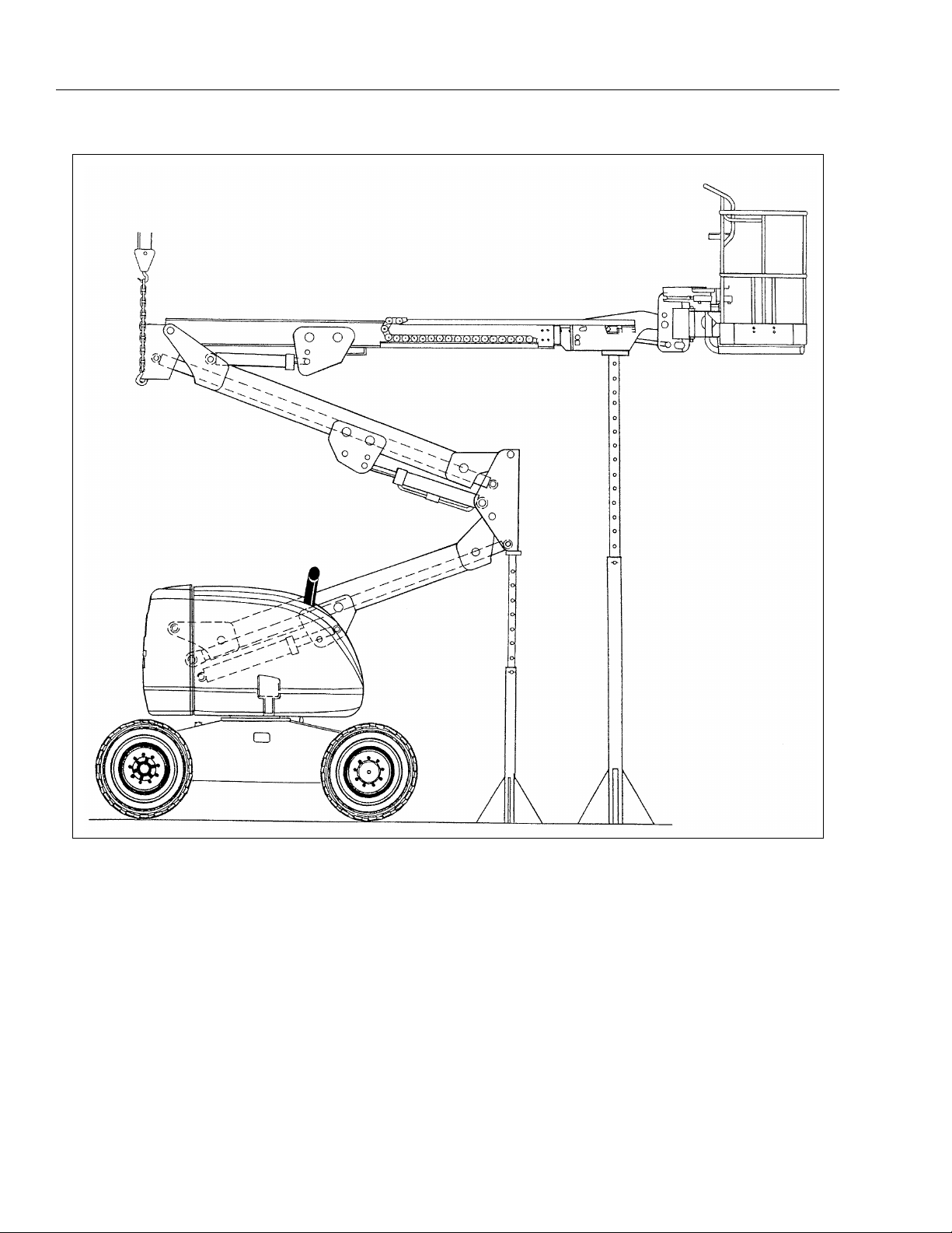
Figure 2-4. Boom Prop Configuration
2-10 – JLG Lift – 3120869

SECTION 2 - PROCEDURES
4. Place the cylinder barrel into a suitable holding fixture.
Figure 2-5. Cylinder Barrel Support
5. Mark cylinder head and barrel with a center punch
for easy realignment. Using an allen wrench, loosen
the cylinder head retainer cap screws, and remove
cap screws from cylinder barrel.
7. Attach a suitable pulling device to the cylinder rod
port block end or cylinder rod end, as applicable.
EXTREME CARE SHOULD BE TAKEN WHEN REMOVING THE CYLINDER ROD, HEAD, AND PISTON. AVOID PULLING THE ROD OFFCENTER, WHICH COULD CAUSE DAMAGE TO THE PISTON AND
CYLINDER BARREL SURFACES.
8. With the barrel clamped securely, apply pressure to
the rod pulling device and carefully withdraw the
complete rod assembly from the cylinder barrel.
Figure 2-6. Capscrew Removal
NOTE: St eps 6 applies only t o the lower lift and tele scope
cylinders.
6. Using a spanner wrench, loosen the end cap or
head retainer, and remove from cylinder barrel.
Figure 2-7. Cylinder Rod Support
9. Using suitable protection, clamp the cylinder rod in
a vise or similar holding fixture as close to the piston
as possible.
10. Loosen and remove the cap screw(s), if applicable,
which attach the tapered bushing to the piston.
11. Insert the cap screw(s) in the threaded holes in the
outer piece of the tapered bushing. Progressively
tighten the cap screw(s) until the bushing is loose
on the piston.
3120869 – JLG Lift – 2-11

SECTION 2 - PROCEDURES
Figure 2-8. Tapered Bushing Removal
12. Remove the bushing from the piston.
13. Screw the piston CCW, by hand, and remove the
piston from cylinder rod.
14. Remove and discard the piston o-rings, seal rings,
and backup rings.
15. Remove piston spacer, if applicable, from the rod.
16. Remove the rod from the holding fixture. Remove
the cylinder head gland and retainer plate, if applicable. Discard the o-rings, back-up rings, rod seals,
and wiper seals.
Cleaning and Inspection
1. Clean all parts thoroughly in an approved cleaning
solvent.
2. Inspect the cylinder rod for scoring, tapering, ovality,
or other damage. If necessary, dress rod with
Scotch Brite or equivalent. Replace rod if necessary.
3. Inspect threaded portion of rod for excessive damage. Dress threads as necessary.
7. Inspect threaded portion of piston for damage.
Dress threads as necessary.
8. Inspect seal and o-ring grooves in piston for burrs
and sharp edges. Dress applicable surfaces as necessary.
9. Inspect cylinder head inside diameter for scoring or
other damage and for ovality and tapering. Replace
as necessary.
10. Inspect threaded portion of head for damage. Dress
threads as necessary.
11. Inspect seal and o-ring grooves in head for burrs
and sharp edges. Dress applicable surfaces as necessary.
12. Inspect cylinder head outside diameter for scoring
or other damage and ovality and tapering. Replace
as necessary.
13. If applicable, inspect rod and barrel bearings for
signs of correct excessive wear or damage. Replace
as necessary.
a. Thoroughly clean hole, (steel bushing) of burrs,
dirt etc. to facilitate bearing installation.
b. Inspect steel bushing for wear or other damage.
If steel bushing is worn or damaged, rod/barrel
must be replaced.
c. Lubricate inside of the steel bushing with WD40
prior to bearing installation.
d. Using an arbor of the correct size, carefully
press the bearing into steel bushing.
NOTE: Ins tall pin in to the Gar- Max bearin g dry. Lubricati on
is not required with nickel plated pins and bearings.
4. Inspect inner surface of cylinder barrel tube for scoring or other damage. Check inside diameter for
tapering or ovality. Replace if necessary.
5. Inspect threaded portion of barrel for damage. Dress
threads as necessary.
6. Inspect piston surface for damage and scoring and
for distortion. Dress piston surface or replace piston
as necessary.
Figure 2-9. Gar-Max Bearing Installation
14. Inspect travel limiting collar or spacer for burrs and
sharp edges. If necessary, dress inside diameter
surface with Scotch Brite or equivalent.
2-12 – JLG Lift – 3120869

SECTION 2 - PROCEDURES
15. If applicable, inspect port block fittings and holding
valve. Replace as necessary.
16. Inspect the oil ports for blockage or the presence of
dirt or other foreign material. Repair as necessary.
17. If applicable, inspect piston rings for cracks or other
damage. Replace as necessary.
Assembly
NOTE: Prior to cylinder assembly, ensure that the proper
cylinder seal kit is us ed . Se e your JLG P a rts Manua l.
Apply a light film of hydraulic oil to all components
prior to assembly.
1. A special tool is used to install a new rod seal into
the applicable cylinder head gland groove.
2. Use a soft mallet to tap a new wiper seal into the
applicable cylinder head gland groove. Install a new
wear ring into the applicable cylinder head gland
groove.
Figure 2-11. Wiper Seal Installation
3. Place a new o-ring and back-up seal in the applicable outside diameter groove of the cylinder head.
Figure 2-10. Rod Seal Installation
WHEN INSTALLING "POLY-PAK" PISTON SEALS, ENSURE SEALS
ARE INSTALLED PROPERLY. REFER TO WIPER SEAL INSTALLATION FOR CORRECT SEAL ORIENTATION. IMPROPER SEAL
INSTALLATION COULD RESULT IN CYLINDER LEAKAGE AND
IMPROPER CYLINDER OPERATION.
Figure 2-12. Installation of Head Seal Kit
4. Install washer ring onto rod, carefully install the head
gland on the rod, ensuring that the wiper and rod
seals are not damaged or dislodged. Push the head
along the rod to the rod end, as applicable.
5. Carefully slide the piston spacer on the rod.
6. If applicable, correctly place new o-ring in the inner
piston diameter groove. (The backup ring side facing the O-ring is grooved.)
3120869 – JLG Lift – 2-13

SECTION 2 - PROCEDURES
Figure 2-13. Piston Seal Kit Installation
7. If applicable, correctly place new seals and guide
lock rings in the outer piston diameter groove. (A
tube, with I.D. slightly larger than the O.D.of the piston is recommended to install the solid seal.)
NOTE: The backup rings for the solid seal have a radius on
one side. This side faces the solid seal.(See magnified insert in Figure 2-13.)The split of seals and
backup rings are to be positi oned so a s not t o be in
alignment with each other.
WHEN REBUILDING THE STEER, AXLE OSCILLATION, LOWER
LIFT, LEVEL CYLINDER, UPPER LIFT CYLINDER, OR E.A.R. CYLINDERS, APPLY LOCTITE #242 TO TAPERED BUSHING BOLTS,
THEN TIGHTEN SECURELY. (SEE TABLE 2-1 AND 2-2. TORQUE
SPECIFICATIONS).
11. Assemble the tapered bushing loosely into the piston and insert JLG capscrews (not vendor capscrews) through the drilled holes in the bushing and
into the tapped holes in the piston.
8. Using suitable protection, clamp the cylinder rod in
a vise or similar holding fixture as close to piston as
possible.
9. Carefully thread the piston on the cylinder rod hand
tight, ensuring that the o-ring and back-up rings are
not damaged or dislodged.
10. Thread piston onto rod until it abuts the spacer end
and install the tapered bushing.
NOTE: When installing the tapered bushing, piston and m at-
ing end of rod must be free of oil.
Figure 2-14. Tapered Bushing Installation
12. Tighten the capscrews evenly and progressively in
rotation to the specified torque value. (See Table 2-1,
Cylinder Head and Tapered Bushing Torque Specifications.)
13. After the screws have been torqued, tap the tapered
bushing with a hammer (500 to 750 gram) and brass
shaft (approximately 19 mm in diameter) as follows;
a. Place the shaft against the cylinder rod and in
contact with the bushing in the spaces between
the capscrews.
2-14 – JLG Lift – 3120869

SECTION 2 - PROCEDURES
b. Tap each space once; this means the tapered
bushing is tapped 3 times as there are 3 spaces
between the capscrews.
Figure 2-15. Seating the Tapered Bearing
14. Retorque the capscrews evenly and progressively in
rotation to the specified torque value. (See Table 2-1,
Cylinder Head and Tapered Bushing Torque Specifications.)
15. Remove the cylinder rod from the holding fixture.
16. Place new guide locks and seals in the applicable
outside diameter grooves of the cylinder piston.
(See Figure 2-28. Piston Seal Kit Installation.)
18. With barrel clamped securely, and while adequately
supporting the rod, insert the piston end into the
barrel cylinder. Ensure that the piston loading o-ring
and seal ring are not damaged or dislodged.
19. Continue pushing the rod into the barrel until the cylinder head gland can be inserted into the barrel cylinder.
20. Secure the cylinder head gland using the washer
ring and socket head bolts. See Table 2-1 and 2-3.
Torque Specifications.)(
Figure 2-17. Rod Assembly Installation
21. After the cylinder has been reassembled, the rod
should be pushed all the way in (fully retracted) prior
to the reinstallation of any holding valve or valves.
22. If applicable, install the cartridge-type holding valve
and fittings in the rod port block, using new o-rings
as applicable. (See Table 2-2. Holding Valve Torque
Specifications).
Figure 2-16. Poly-Pak Piston Seal Installation
17. Position the cylinder barrel in a suitable holding fixture.
EXTREME CARE SHOULD BE TAKEN WHEN INSTALLING THE
CYLINDER ROD, HEAD, AND PISTON. AVOID PULLING THE ROD
OFF-CENTER, WHICH COULD CAUSE DAMAGE TO THE PISTON
AND CYLINDER BARREL SURFACES.
3120869 – JLG Lift – 2-15

SECTION 2 - PROCEDURES
Table 2-1.Cylinder Head and Tapered Bushing Torque
Specifications
Description
Upper Lift Cylinder
Upper Lift Cylinde r (AJ)
Mid Cylinder
Lower Cylinder N/A
E.A.R. Cylinder
Tele Cylinder N/A
Level Cylinder
Axle Oscillation
Cylinder
Steer Cylinder
Head Torque Value
(Wet)
50 ft. lbs.
(68 Nm)
80 ft. lbs.
(109 Nm)
80 ft. lbs.
(109 Nm)
30 ft. lbs
(41 Nm)
80 ft. lbs.
(109 Nm)
30 ft. lbs.
(41 Nm)
30 ft. lbs.
(41 Nm)
Tapered Bushing
Torque Value (Wet)
9 ft. lbs
(12 Nm)
9 ft. lbs
(12 Nm)
9 ft. lbs
(12 Nm)
9 ft. lbs
(12 Nm)
5 ft. lbs.
(9 Nm)
5 ft. lbs.
(9 Nm)
5 ft. lbs.
(9 Nm)
N/A
N/A
2.10 MID AND LOWER LIFT CYLINDER
BLEEDING PROCEDURE
NOTE: Bleeding procedure should only be necessary if
rebuilding or replacing lift cylinder.
1. Check oil level in the hydraulic oil tank (all booms
must be retracted). Lay an oil drip pan under the rod
end port block (Mid Cylinder) and crack bleeder
open from the fitting in the port block.
2. From the platform, turn the speed control knob to
the slow position.
3. Lift up very slowly. This will force any air out of the
circuit. If the lower boom is not extending, turn the
speed control up very slowly until the lower boom
starts to move.
4. Raise the lower boom approx. 30.5 cm (1 foot), then
close bleeder while the boom is still moving.
5. Lift down all the way.
6. Repeat this procedure until all air has been purged
from the circuit. Re-check the hydraulic oil level.
7. To test, cycle the lower lift function 3-4 times to see if
both cylinders stop at the same time when fully
extended.
Table 2-2.Holding Valve Torque Specification
Description Torque Value
SUN - 7/8 HEX M20 x 1. 5 THDS. 30-35 ft.lbs.
(41-48 Nm)
SUN - 1 1/8 HEX 1-14 UNS THDS.
SUN - 1 1/4 HEX M36 x 2 THDS.
RACINE - 1 1/8 HEX 1 1/16-12 THDS.
RACINE - 1 3/8 HEX 1 3/16-12 THDS.
RACINE - 1 7/8 HEX 1 5/8-12 THDS.
IF THE CYLINDER IS TO BE TESTED PRIOR TO INSTALLATION ON
THE MACHINE, EXTREME CARE SHOULD BE USED TO INSURE
THAT THE OUTER END OF THE ROD IS SUPPORTED. USE
EITHER A TRAVELING OVERHEAD HOIST, FORK-LIFT, OR OTHER
MEANS TO SUPPORT THE OVERHANGING WEIGHT OF THE
EXTENDING ROD.
45-50 ft.lbs.
(61-68 Nm)
150-160 ft.lbs.
(204-217 Nm)
50-55 ft.lbs.
(68-75 Nm)
75-80 ft.lbs.
(102-109 Nm)
100-110 ft.lbs.
(136-149 Nm)
2.11 HYDRAULIC PUMP (GEAR)
Disassembly
NOTE: The following gene ral in struction s also apply to m ulti-
ple section gear pumps, the only extra parts are the
coupling between the drive s ha fts and the center dis tance plate which divides the two pump sections.
This repair procedure also applies to the "W" series
Gear Motors.
1. It is very important to work in a clean work area
when repairing hydraulic products. Plug ports and
wash exterior of pump with a proper cleaning solvent before continuing.
2-16 – JLG Lift – 3120869

SECTION 2 - PROCEDURES
2. Remove port plugs and drain oil from pump.
3. Use a permanent marker pen to mark a line across
the mounting flange, gear housing and end cover.
This will assure proper reassembly and rotation of
pump.
4. Remove key from drive shaft if applicable.
8. Lift and remove end cover.
9. Carefully remove gear housing and place on work
bench. Make sure the rear bearing block remains on
the drive and idler shafts.
5. Clamp the mounting flange in a protected jaw vise
with the pump shaft facing down.
6. Loosen the four metric hex head bolts.
7. Remove pump from vise and place on clean work
bench, remove the four hex head bolts and spacers
if applicable.
10. Remove rear bearing block from drive and idler
shafts.
3120869 – JLG Lift – 2-17

SECTION 2 - PROCEDURES
11. Remove idler shaft from bearing block.
12. Remove drive shaft from mounting flange. There is
no need to protect the shaft seal as it will be
replaced as a new item.
14. Turn the mounting flange over, with the shaft seal up,
and remove the retaining ring with proper snap ring
pliers.
15. Remove the oil seal from mounting flange, be careful not to mar or scratch the seal bore.
16. Remove the dowel pins from the gear housing. Do
not lose pins.
13. Remove the front bearing block.
17. Remove seals from both bearing blocks and discard.
2-18 – JLG Lift – 3120869

SECTION 2 - PROCEDURES
Inspect Parts For Wear
1. Clean and dry all parts thoroughly prior to inspection. It is not necessary to inspect the seals as they
will be placed as new items.
2. Check drive shaft spine for twisted or broken teeth,
check keyed drive shaft for broken or chipped keyway. No marks or grooves on shaft in seal area,
some discoloration of shaft is allowable.
3. Inspect both the drive gear shaft and idler gear
shafts at the bearing points and seal area for rough
surfaces and excessive wear.
4. Inspect gear face for scoring or excessive wear. If
the face edge of gear teeth are sharp, they will mill
into the bearing blocks. If wear has occurred, the
parts are unusable.
5. Inspect bearing blocks for excessive wear or scoring
on the surfaces which are in contact with the gears.
Also inspect the bearings for excessive wear or scoring.
6. Inspect the area inside the gear housing. It is normal
for the surface inside the gear housing to show a
clean "wipe" on the inside surface on the intake side.
There should not be excessive wear or deep
scratches and gouges.
3120869 – JLG Lift – 2-19

SECTION 2 - PROCEDURES
General Information
It is important that the relationship of the mounting flange,
bearing blocks and gear housing is correct. Failure to
properly assemble this pump will result with little or no
flow at rated pressure.
Reverse Shaft Rotation of Pump
NOTE: This pump is not bi-rotational, if the shaft rotation
must be changed the following procedure must be
followed.
Reversing the shaft rotation of the "W" series gear pump
may be accomplished by rotating, as a group, the two
bearing blocks and the gear housing 180° in relationship
to the remaining parts of the pump. This procedure will
place the pressure port on the opposite side of the pump
from its original position.
Assembly
NOTE: New seals should be installed upon reassembly of
pump or motor. deter to page 8 for the necessary kit
part numbers for the W-600, W-900 and W-1500
pumps and motors.
bore. Uniform pressure must be used to prevent
misalignment or damage to the seal.
2. Install retaining ring in groove in seal bore of mounting flange.
1. Install new shaft seal in mounting flange with part
lumber side facing outboard. Press the seal into the
seal lore until the seal reaches the bottom of the
3. Place front and back bearing blocks on a clean surface with the E-seal grooves facing up. Apply a light
coating of petroleum jelly in the grooves. Also coat
the E-seal and backup with the petroleum jelly, this
will help keep the seals in place during reassembly.
4. Place the E-seals, flat side outward, into the grooves
in both bearing blocks. Follow by carefully placing
the backup ring, flat side outward, in the groove
made by the E-seal and the groove in the bearing
block. (Note: in the W900 series pump, in the center
of the backup ring and E-seal there is a notch make
sure that these notches line up so the backup ring
will set flush with the E-seal). The backup ring in the
W1500 pump is symmetrical.
2-20 – JLG Lift – 3120869

SECTION 2 - PROCEDURES
5. Place mounting flange, with shaft seal side down, on
a clean flat surface.
6. Apply a light coating of petroleum jelly to the
exposed face of the front bearing block.
7. Insert the drive end of the drive shaft through the
bearing block with the seal side down, and the open
side of the E-seal pointing to the intake side of the
pump.
8. Install the seal sleeve over the drive shaft and carefully slide the drive shaft through the shaft seal.
Remove the seal sleeve from shaft.
11. Install two dowel pins in the holes in the mounting
flange or two long dowel pins through gear housing
if pump is a multiple section pump.
12. To install the O-rings in the gear housing, apply a
light coating of petroleum jelly in the grooves on
both sides of the gear housing. Also coat the new Orings and install them in the grooves.
13. Gently slide the gear housing over the rear bearing
block assembly, slide housing down until the housing engages the dowel pins. Press firmly in place
with hands, do not force or use any tool. Check to
9. Install the idler gear shaft in the remaining position in
the bearing block. Apply a light coat of clean oil to
the face of the drive and idler gears.
10. Pick up the rear bearing block, with seal side up and
with open end of the E-seal facing the intake side of
the pump, place over the drive and idler gear shafts.
make sure the in-take port in the housing is on the
same side as the open end of the E-seal and that the
marked lines on the mounting flange and gear housing are in alignment.
3120869 – JLG Lift – 2-21

SECTION 2 - PROCEDURES
14. The surface of the rear bearing block should be
slightly below the face of the gear housing. If the
bearing block sits higher then the rear face of the
gear housing then the E-seal or o-ring have shifted
out of the groove. If this is the case, remove the gear
housing and check for proper seal installation.
15. Install the two remaining dowel pins in the rear of the
gear housing, if applicable, and place the end cover
over the back of the pump.
19. Place a small amount of clean oil in the inlet of the
pump and rotate the drive shaft away from the inlet
one revolution. If the drive shaft binds, disassemble
the pump and check for assembly problems, then
reassemble the pump.
20. The name plate located on the end cover contains
the build date code and the model number. Please
refer to this information when corresponding with
the J.S. Barnes Service Department.
Table 2-3.Hydraulic Pump Bolt Torque Chart
Pump Series Thread Size
Tor que
Values, Black
Oxide End
Cover
Torque
Values, Zinc
Plated End
Cover
16. Install the four spacers, if applicable, and hex head
bolts through the bolt holes in the end cover, hand
tighten.
17. Place mounting flange of the pump back in the protected jawed vise and alternately torque the bolts to
the torque specifications in the torque chart. All
torque figures are for "dry torque” bolts.
18. Remove pump from vise.
W-600
W-900
W-1500
M 8 x 1.25
M 10 x 1.5
M 12 x 1.75
18-21 ft.lb.
24-30 Nm
50-55 ft.lb.
68-75 Nm
80-85 ft.lb.
108-115 Nm
16-18 ft.lb.
21.7-24.4 Nm
38-43 ft.lb.
51.5-58.3 Nm
68-73 ft.lb.
92.2-99 Nm
2-22 – JLG Lift – 3120869

SECTION 2 - PROCEDURES
Placing Pump Back Into Service
1. If shop test stand is available, the following procedure for testing rebuilt pumps is recommended:
a. Mount pump on test stand making sure that the
proper level of clean oil is available in the reservoir. Check suction line for leaks and obstructions.
b. Start pump and run for three minutes at zero
pressure.
c. Intermittently load pump to 34.5 Bar (500 psi) for
three minutes.
d. Intermittently load pump to 69 Bar (1000 psi) for
three minutes.
e. Intermittently load pump to 138 Bar (2000 psi)
for three minutes.
f. Remove pump from test stand and check for
freeness of drive shaft. Check pump for signs of
external leakage.
2. If shop test stand is not available, the following procedure for testing rebuilt pumps is recommended:
a. For engine driven pumps, mount pump on
equipment and run pump at 1/2 engine speed at
zero pressure for three minutes.
b. By operating control valve, build pressure inter-
mittently for three minutes.
c. Increase engine speed to full throttle and build
pressure intermittently for three minutes.
d. Stop engine and check pump for external leaks.
2. At the positions indicated on the figure titled Swing
Bearing Tolerance Boom Placement. Try and insert
the 0.0015" feeler gauge between the bolt head and
hardened washer at the arrow indicated position.
3. Assure that the 0.0015" feeler gauge will not penetrate under the bolt head to the bolt shank.
4. Swing the turntable 90 degrees, and check some
selected bolts at the new position.
5. Continue rotating the turntable at 90 degrees intervals until a sampling of bolts have been checked in
all quadrants.
Check the turntable to bearing. Attach bolts as follows:
1. Elevate the fully retracted boom to 70 degrees (full
elevation).
2. At the positions indicated in the figure below, try and
insert the 0.0015" feeler gauge between the bolt
head and hardened washer at the arrow indicated
position.
.0015" Feeler Gauge
2.12 SWING BEARING
Turntable Bearing Mounting Bolt Condition
Check.
NOTE: This check is designed to replace the existing bear-
ing bolt torque checks on JLG Lifts in service. This
check must be performed after the first 50 hours of
Figure 2-19. Swing Bearing Feeler Gauge Check
3. Lower the boom to horizontal and fully extend the
boom.
4. At the position indicated on Figure 2-30. try and
insert the 0.0015" feeler gauge between the bolt
head and hardened washer at the arrow indicated
position.
machine operation and every 600 hours of machine
operation thereafter. If during this check any bolts
are found to be missing or loose, replace missing or
loose bolts with new bolts and torque to the value
specified in the torque chart, after lubricating the bolt
threads with loctite #271. After replacing and
retorquing bolt or bolts recheck all existing bolts for
looseness.
Check the frame to bearing. Attach bolts as follows:
1. Elevate the fully retracted boom to 70 degrees (full
elevation).
3120869 – JLG Lift – 2-23

SECTION 2 - PROCEDURES
TO
REMOTE
Figure 2-18. Swing Bearing Installation
2-24 – JLG Lift – 3120869

SECTION 2 - PROCEDURES
Wear Tolerance
1. With the boom positioned over the side of the
machine, the Upper Boom horizontal with telescope
fully extended and Mid/Lower Boom stowed, using a
magnetic base dial indicator, measure and record
the distance between the swing bearing and turntable.
2. At the same point, with the boom positioned over
the side of the machine, the Upper Boom fully elevated and the Mid/Lower Boom fully elevated, using
a magnetic base dial indicator, measure and record
the distance between the swing bearing and turntable.
TURNTABLE REF.
MEASURING
POINT
FRAME REF.
Figure 2-20. Swing Bearing Tolerance Measuring
Point
3. If a difference greater than 1.40 mm (0.057 in.) is
determined, the swing bearing should be replaced.
4. If a difference less than 1.40 mm (0.057 in.) is determined, and any of the following conditions exist, the
bearing should be removed.
a. Metal particles in the grease.
b. Increased drive power.
c. Noise.
d. Rough rotation.
5. If bearing inspection shows no defects, reassemble
bearing and return to service.
SWING
BEARING
Replacement of Swing Bearing
Removal of the swing bearing is as follows:
1. Attach an adequate support sling to the boom and
draw all slack from sling. Prop or block the boom if
feasible.
2. Tag and disconnect hydraulic lines running through
center of turntable and frame. Use a suitable container to retain any residual hydraulic fluid. Cap lines
and ports.
3. Attach suitable overhead lifting equipment to the
base of turntable weldment.
4. Use a suitable tool to scribe a line on the inner race
of the swing bearing and on the underside of the
turntable. This will aid in aligning the bearing upon
installation. Remove bolts, nuts and washers which
attach the turntable to the bearing inner race. Discard nuts and bolts.
5. Use the lifting equipment to carefully lift the complete turntable assembly from the bearing. Ensure
that no damage occurs to the turntable, bearing or
frame mounted components.
6. Carefully place the turntable on a suitably supported
trestle.
7. Use a suitable tool to scribe a line on the outer race
of the swing bearing and the frame. This line will aid
in aligning the bearing upon installation. Remove the
bolts and washers which attach the outer race of the
bearing to the frame. Discard the bolts. Use suitable
lifting equipment to remove the bearing and rotation
box assembly from the frame; move to a clean, suitably supported work area.
8. Remove the two capscrews securing the bearing to
the rotation box to separate the two for inspection.
Installation of the swing bearing is as follows:
1. Install bearing to rotation box with two capscrews,
so that fill plug of bearing is as close to gear as bolt
pattern will allow. Do not tighten capscrews.
2. Line up high spot (blue) of bearing with center tooth
of worm gear. Set backlash to 0.20 - 0.25 mm (0.008
- 0.010 inch). Tighten capscrews as shown in Figure
2-21., Swing Bearing Torquing Sequence.
3120869 – JLG Lift – 2-25

SECTION 2 - PROCEDURES
3. Apply Mobiltac 375NC Open Gear Compound to
bearing and worm gear teeth.
4. Grease bearing with Mobilith SHC Bearing Grease.
Grease fitting is on inside wall of inner race of bearing.
NOTE: If
Mobiltac 375NC
Open Gear Compound or Mobilith
SHC Bearing Grease are not available, Multi-Purpose Grease (MPG) can be substituted, however the
service interval will be shorter.
5. Using suitable lifting equipment, install bearing/rotation box assembly to frame with soft spot (red) 90
degree relative to load axis. If reusing old bearing,
ensure that scribed line of outer race of the bearing
aligns with the scribed mark on the frame.
JLG INDUSTRIES RECOMMENDS THAT ALL REMOVED GRADE 8
BEARING NUTS AND BOLTS BE DISCARDED AND REPLACED
WITH NEW NUTS AND BOLTS. SINCE THE SWING BEARING IS
THE ONLY STRUCTURAL LINK BETWEEN THE FRAME AND
TURNTABLE, IT IS IMPERATIVE THAT SUCH REPLACEMENT
HARDWARE MEETS JLG SPECIFICATIONS. USE OF GENUINE
JLG HARDWARE IS HIGHLY RECOMMENDED.
6. Apply a light coating of Loctite 271 to the new bearing bolts and loosely install the bolts and washers
through the frame and outer race of bearing.
IF COMPRESSED AIR OR ELECTRICALLY OPERATED IMPACT
WRENCH IS USED FOR TIGHTENING THE BEARING ATTACHMENT BOLTS, THE TORQUE SETTING ACCURACY OF THE TOOL
SHOULD BE CHECKED PRIOR TO USE.
7. Following the torque sequence diagram shown in
Figure 2-21., Swing Bearing Torquing Sequence,
tighten the bolts to an initial torque of 237 Nm (175
ft. lbs.). Then following the same sequence, tighten
to a final torque of 326 Nm (240 ft. lbs.).
8. Remove lifting equipment from bearing.
10. Carefully lower the turntable onto the swing bearing.
Ensure that the scribed line of the inner race of the
bearing aligns with the scribed mark on the turntable. If a new swing bearing is used, ensure that the
filler plug fitting is at 90 degrees from the fore and aft
centerline of the turntable.
11. Apply a light coating of Loctite 271 to the new bearing bolts and install through the turntable and inner
race of bearing.
12. Following the torque sequence shown in Figure 2-
21., Swing Bearing Torquing Sequence, tighten the
bolts to an initial torque of 175 ft. lbs. (237 Nm).
Then following the same sequence, tighten the bolts
to 240 ft. lbs (326 Nm).
13. Remove the lifting equipment.
14. Route hydraulic lines through center of turntable and
frame and connect as tagged prior to removal.
15. Using all applicable safety precautions, activate the
hydraulic system and functionally check swing system for proper and safe operation.
2
15
11
2
6
23
19
15
11
7
3
21
17
13
24
9
5
1
7
3
17
13
9
5
18
6
10
14
10
14
18
22
4
8
4
8
12
16
20
12
16
1
Figure 2-21. Swing Bearing Torquing Sequence
9. Use suitable lifting equipment to carefully position
the turntable assembly above the machine frame.
Swing Bearing Torque Values
1. Dry - 298 Nm (220 ft. lbs.).
2. Loctite - 326 Nm (240 ft. lbs.).
Updated 11-1-99
2-26 – JLG Lift – 3120869

2.13 WORM GEAR
Checking Worm Gear End Play
NOTE: JLG I ndustries req uires that a an nual inspection be
performed on the worm gear end play.
SECTION 2 - PROCEDURES
Fig 2 Adjusting End Play.
1. Using a dial indicator, measure end play of worm
gear, by applying side to side movement by hand to
platform.
2. If tolerance exceeds 0.254 mm (0.010"), reduce end
play to less than 0.127 mm (0.005"). Refer to Adjusting End Play.
Allowable Tolerance
.001 to .005
()
Adjusting End Play
1. Remove end plate.
2. Measure and record total thickness of existing shim
pack.
Parts Required
7016682 Shim Kit Includes;
3 of 0.005" thick shims
SHIMS
END PLATE
3 of 0.0075" thick shims
3 of 0.010" thick shims
2.14 BOOM SYNCHRONIZING PROCEDURE
NOTE: If the Lower Boom assembly does not fully lower:
1. Remove all personnel from the platform.
2. Pull the red knob located under the main control
valve.
3. From Ground Control, activate the lift control switch,
raise Lower Boom 2 meters (6 feet).
4. After raising Lower Boom, release the red knob.
5. Activate Lower Boom Down, fully lower boom.
6. Repeat step 1 thru 5 if necessary.
3. Determine thickness of shim pack required to obtain
0.025 - 0.127 mm (0.001" - 0.005") end play.
4. Adjust shim pack thickness as required to obtain
proper end play. Reduce end play by removing
thicker shims and replacing with thinner shims,
included in kit.
5. Replace end plate and torque bolts to 122 Nm (90 ft.
Figure 2-22. Synchronizing Valve
lbs.).
6. Recheck end play.
3120869 – JLG Lift – 2-27

SECTION 2 - PROCEDURES
2.15 EXTEND-A-REACH
Removal
1. Place the Extend-A-Reach in a horizontal position
and support the complete assembly with adequate
blocking.
2. Remove the Platform as follows:
a. Disconnect the electrical connectors going into
the platform control box.
b. Remove the bolts, nuts, and washers connect-
ing the platform basket to the platform support.
c. Using a suitable lifting device, remove the plat-
form basket from the platform support.
3. Tag and disconnect the hydraulic lines running to
the extend-a-reach. Use a suitable container to collect any residual fluid. Cap the hydraulic lines and
ports.
4. Remove the hardware securing the extend-a-reach
pivot pin at the boom. Using a suitable brass drift
and hammer, remove the pin from the fly boom. Use
a suitable lifting device and remove the extend a
reach.
2.16 ADJUSTMENT PROCEDURE FOR
LOCKOUT VALVE
1. With the turntable centered, adjust the bracket with
the washers to push the plunger in 7.9 mm ± 1.6
mm (5/16" ± 1/16").
WASHER
BRACKET
LOCKOUT
VALVE
TOP TUBE
BOTTOM TUBE
ROTATE CYLINDER
PLATFORM SUPPORT
PIVOT SHAFT
Figure 2-23. Extend-A-Reach
GUARD
E.A.R. CYLINDER
CHECK VALVE
2-28 – JLG Lift – 3120869

AXLE
PIVOT
PIN
SECTION 2 - PROCEDURES
LOCKOUT
VALVE
OSCILLA TION
CYLINDER
SPINDLE
TIE
ROD
Figure 2-24. Front Axle
2. The ideal adjustment is 9.5 mm (3/8"). Do not push
the plunger in more that 9.5 mm (3/8"). The extra
adjustment is needed for the turntable bearing play.
2.17 TORQUE HUB (PRIOR TO S/N 39594)
Ring Gear/Cover Disassembly
1. Loosen the bolts (1) holding the disengage cap (2)
in place. Remove the disengage cap.
2. Remove the disengage rod (3) from the ring gear/
cover (4).
3. Take out the O-ring (5) from the ring gear/cover.
4. Remove the pipe plugs (6) from the ring gear cover.
Carrier Disassembly
1. Stand the carrier (8) on its side.
2. Take a punch and a hammer amid drive the roll pin
(9) into the planet shaft (10). Make sure that the pin
is in enough to slide the planet shaft (10) out of the
carrier (8).
Figure 2-25. Ring Gear/Cover
3. Rotate the planet shaft (10) 180 degrees, then drive
the roll pin (9) out of the planet shaft (10) and discard the roll pin (9).
4. Remove the planet gear (11) and the flat tanged
washers (12) from the carrier.
3120869 – JLG Lift – 2-29

SECTION 2 - PROCEDURES
Figure 2-26. Carrier
5. Repeat steps 2 thru 4 for the remaining two planet
gears.
6. Remove the bearing needles (13) and the thrust
spacer (14) from the planet gear (11).
Hub-Spindle Disassembly
7. Using a hammer and a thin barstock punch, drive
the cups out of the housing.
Main Disassembly
1. Remove coupling (25) from spindle (21).
2. Remove retaining ring (26) from coupling (25).
3. Remove the hex socket screws (7) from the ring
gear cover (4).
4. Remove the ring gear cover (4) from the housing
(16).
5. Remove the thrust washer (27) from the counterbore
of the carrier (8)
6. Remove the carrier (8) along with the sun gear (28).
7. Remove the input shaft (29). Take out the bottom
thrust washer (27).
8. Take off the thrust washer (30) from the spindle
counterbore.
9. Remove the internal gear (31) from the spindle (21).
10. Remove the retaining ring (32) from the input shaft
(29), and discard the retaining ring.
11. Take the O-Ring (33) out of the 0-Ring groove on the
spindle (21).
NOTE: If your unit does not have studs, then skip step 1.
1. Hammer the studs (15) out of the flange of the housing (16).
SAFETY GLASSES MUST BE WORN DURING THIS STEP.
2. Remove the retaining ring (17) from spindle counterbore.
3. Remove the spacer (18) and the spring (19).
4. Using retaining ring pliers, remove the retaining ring
(20) from the spindle (21) discard the retaining ring
at this time. Remove the thrust spacer (22) from the
spindle (21).
5. Place on I-beams and press the top of the spindle
through the housing.
NOTE: The outboard bearing and seal will have to be
removed from the spindle. You will have to scrap out
the seal and bearing to remove them from the spindle.
6. Remove the inboard bearing (23) from the inboard
cup (24).
Carrier Sub-Assembly
1. Put a generous amount of grease into the planet
gear (11).
2. Line the inside of the planet gear (11) with sixteen
bearing needles (13). Put thrust spacer (14) on top
of bearing needles (13), then place 16 more bearing
needles (13) on top of the thrust Spacer (14).
3. Repeat step 2 for the two remaining planet gears.
4. Stand carrier on its side. Insert planet shaft (10) into
the hole on the side of the carrier (8) with roll pin
last.
5. Place flat tanged washer (12) onto the planet shaft
so that the bump on the flat tanged washer is
located towards the interior of the carrier, and is
lined up with the slot on the carrier (8).
2-30 – JLG Lift – 3120869

SECTION 2 - PROCEDURES
Figure 2-27. Torque Hub (Prior to S/N 39594) - Exploded View
3120869 – JLG Lift – 2-31

SECTION 2 - PROCEDURES
Figure 2-28. Torque Hub (Prior to S/N 39594) - Cutaway View
2-32 – JLG Lift – 3120869

SECTION 2 - PROCEDURES
6. Place the assembled planet gear (11), large end
towards the roll pin onto the planet shaft (10).
7. Push the planet shaft (10) through until it reaches
the other side of the planet gear (11). Place the other
flat tanged washer (12) onto the shaft so that the
bump is on the internal side of the carrier, and is
lined up with the slot on the carrier.
8. Push the planet shaft (13) all the way through the
carrier (8) until the roll pin holes line up.
9. Using an alignment punch, align the roll pin holes in
the carrier (8) with the roll pin holes in the planet
shaft (10) and drive the roll pin (9) into the hole until
it is flush with the carrier housing.
10. Repeat steps 4 to 10 for the remaining two planet
gears.
11. At this point the carrier sub-assembly is complete.
Ring Gear/Cover Sub-Assembly
1. Grease and install O-Ring (5) into ring gear/cover
(4).
2. Place disengage cap (2) on ring gear/cover (4) with
the nipple facing out.
3. Fasten disengage cap (2) with two bolts (1). Torque
bolts to 8 - 9 Nm (70-80 in-lbs).
4. Insert disengage rod (3) into ring gear/cover (2).
5. Install pipe plugs (6) into ring gear/cover (4).
Hub-Spindle Sub-Assembly
NOTE: If your unit does not have studs, skip this step.
1. Place the hub with the large diameter up on a flat
surface. Using a bearing cup pressing tool press the
inboard cup (24) into the housing (16). Turn the unit
over.
2. Using a stud fixture and a hammer, carefully press
studs (15) into the housing (16). If there is not a stud
fixture available anything that can suspend the housing in the air can be used.
3. With the unit still in the fixture, press in the outboard
cup (24).
4. Place outboard bearing (23) into the outboard cup.
5. With the housing still in the stud fixture, with a seal
pressing fixture, press the seal (34) with the closed
face up into the small diameter of the housing.
6. Place spindle (21) on a flat surface with large diameter down. Coat the seal shoulder with grease.
7. Place the hub onto spindle. Press bearing cone (23)
onto the spindle.
8. Press the inboard bearing cone (23) onto the spindle until you get slight drag when rotating the hub.
9. Place the spacer (18) on the bearing cone. Install
retaining ring (17) onto spindle (21). Do not use
retaining ring pliers.
SAFETY GLASSES MUST BE WORN DURING THIS STEP.
10. Insert Spring (15) into spindle (1A) counterbore.
Place Spacer (16) on top of spring. Install retaining
ring (17) into spindle counterbore using retaining
ring pliers.
Main Assembly
NOTE: All components should receive a generous amount
of lubricant oil as they are being assembled.
1. Place hub-spindle sub-assembly on a flat surface.
2. Grease and install O-Ring (33) onto hub pilot.
3. Install retaining ring (32) onto input shaft (29) using
retaining ring pliers.
4. Install input shaft (29) into spindle (21).
5. Install internal gear (31) onto spindle (21) spline.
6. Place thrust washer (27) on spindle (21) pilot.
7. Place thrust washer (20) into spindle (21) counterbore.
8. Time the assembled carrier with the large diameter
of the cluster gears facing up. Make sure that all
three punch marks on the gears are in the 12 o’clock
position and secure the gear teeth.
9. Install the sun gear (28) into the cluster gears (11).
Be sure that the punch marks remain in their correct
location.
3120869 – JLG Lift – 2-33

SECTION 2 - PROCEDURES
10. Install carrier sub-assembly with sun gear (28) onto
input shaft (29) and into internal gear (31). Rotate
the carrier to insure that the timing is correct.
11. Place second washer (27) into the counterbore of
the carrier(8).
12. Install Ring gear/cover (4) sub-assembly onto the
hub making sure that the holes on the ring gear/
cover (4) match up with the holes on the hub.
13. Secure ring gear/cover (4) to hub using three hex
socket screws (7). Torque screws 20 - 27 Nm (15-20
ft-lbs).
14. Install retaining ring (26) into coupling (25) using
retaining ring pliers.
15. Insert coupling (25) into spindle (21) counterbore.
16. Roll check unit. To do this, you would turn the number of turns in each direction that the unit is being
reduced. For example a 19 to 1 reduction would
require 19 turns to the left and 19 turns to the right.
17. Air check unit by plugging up the input diameter of
the spindle and filling the unit with air. If the unit
retains all of the air after 15 minutes then it is good.
2.18 TORQUE HUB (S/N 39594 TO PRESENT)
NOTE: All index number references in parentheses in the
following paragraphs are in reference to Figure 2-
29., Torque Hub (S/N 39594 to Present) - Cutaway
View
23. Remove thrust washer (11) from the counterbore in
top of carrier (3A).
24. Remove input gear (8) from the middle of carrier
sub-assembly.
25. Lift ring gear (4) off of hub (1G).
26. Lift carrier sub-assembly (3) out of hub (1G).
27. Remove the thrust spacer (9) from input shaft (7) in
the middle of spindle (1A).
28. Lift input shaft sub-assembly (7) out of middle of
spindle (1A), and stand input shaft (7A) on its
splined end.
WEAR SAFETY GLASSES DURING THIS STEP BEING AWARE
THAT SPRING AND SPACERS COMPRESSED BY RETAINING
RING MAY POP SUDDENLY OFF SHAFT WHEN REMOVING THE
RETAINING RING.
29. Using retaining ring pliers, remove the retaining ring
(7B) from the groove on the input shaft (7A).
30. Remove one spacer (7D), one spring (7C), and
other spacer (7D) from input shaft (7A) on its splined
end.
31. Remove thrust washer (11) from around spindle
(1A).
32. Lift internal gear (2) out of hub (1G).
Main Disassembly
18. Turn hub (1G) over on its side. Remove coupling
(14) from the wide end of the spindle (1A).
19. Mark the location of the shoulder bolt holes on outside of ring gear and hub for easy re-alignment
when rebuilding. Remove the four shoulder bolts
(13) and twelve bolts (12) from cover (6).
20. Remove the 16 flatwashers (16) from cover (6).
21. Lift cover sub assembly (6) off of ring gear (4), and
set cover on the table, interior side facing up.
BEWARE OF SHARP EDGES IN THE COUNTERBORE WHEN
REMOVING THE O-RING.
22. Remove o-ring (5) from the counterbore around the
edge of cover (6A). Discard the o-ring.
NOTE: If o-ring is not in the cover counterbore, it is in the
ring gear counterbore. Remove it from the hub and
discard it.
BEWARE OF SHARP EDGES IN THE COUNTERBORE WHEN
REMOVING THE O-RING.
33. Remove o-ring (5) from the counterbore in hub (1G).
Discard o-ring.
Hub-Spindle Disassembly
NOTE: Start with the large end of hub f ac ing up, large end of
spindle facing down.
WEAR SAFETY GLASSES DURING STEP ONE.
1. Remove retaining ring (1I) from around spindle (1A)
in hub (1G).
2. Remove spacer (1H) from around the spindle (1A) in
hub (1G).
2-34 – JLG Lift – 3120869

SECTION 2 - PROCEDURES
Figure 2-29. Torque Hub (S/N 39594 to Present) - Cutaway View
3120869 – JLG Lift – 2-35

SECTION 2 - PROCEDURES
3. Set hub (1G), small end/spindle facing down, up on
something that will support the hub’s flange while it
lifts hub up so spindle is not resting on anything.
Carefully press or hammer spindle (1A) down out of
hub (1G).
NOTE: If seal (1B) and bearing cone (1D) come out of hub
and rest on spindle, remove these parts from the
spindle and set them aside. Discard the seal.
4. If seal and bearing cone did not come out of the
small end of hub (1G) when the spindle was pressed
out of the hub, remove seal (1B) and bearing cone
(1D) from the small end of hub (1G). Discard the
seal.
5. Bearing cone (1F) should be lying loose in wide end
of hub (1G). Remove the bearing cone (1F) from
inside of the hub (1G).
NOTE: If using a punch and hammer, make sure not to
strike the counterbore with the punch when removing the bearing cup.
6. Remove the bearing cup (1C) from the counterbore
in the small end of the hub (1G).
NOTE: If using a punch and hammer, make sure not to
strike the counterbore with the punch when removing the bearing cup.
7. Turn hub (1G) over and lift it out of the flange-support. Remove the bearing cup (1E) from the counterbore in the wide end of hub (1G).
8. Turn hub (1G) over onto it’s small end. Remove two
pipe plugs (1J) from the two pipe plug holes in the
side of the hub (1G)
9. Press the studs (1N) out of the hub (1G).
Cover Disassembly
Carrier Disassembly
NOTE: When you remove the needle rollers from the cluster
gears, discard the old needle rollers and use new
ones during re-assembly.
1. Using a punch and hammer, drive roll pin (3G) into
planet shaft (3E).
NOTE: If the roll pin is not driven all the way into the planet
shaft, the carrier could be damaged when removing
the planet shaft from the carrier.
2. Using a punch and hammer, drive planet shaft (3E)
out of the planet shaft hole in the carrier housing
(3A).
3. When removing planet shaft (3E) from the carrier
housing, one thrust washer (3B), one cluster gear
(3F), and one more thrust washer (3B) will come off
of the planet shaft and come to rest inside the carrier. Remove these parts from inside the carrier.
4. Remove 16 needle rollers (3C) from inside one end
of cluster gear (3F). Discard the needle rollers.
5. Remove one spacer (3D) from inside the cluster
gear (3F).
6. REmove the remaining 16 needle rollers (3C) from
the other side of cluster gear (3F). Discard the needle rollers.
7. Repeat steps 1 thru 6 to remove and disassemble
the two remaining clusters.
Assembly of the Carrier
1. Apply grease to the inside of one cluster gear (3F)
and line one half of cluster gear with 16 needle rollers (3C).
1. Remove the two bolts (6C) holding the disconnect
cap (6D) to the cover (6A).
2. Remove the disconnect cap (6D) from on top of
cover cap (6B) and cover (6A).
3. Remove the two bolts (6C) holding the cover cap
(6B) and cover (6A).
4. Remove cover cap (6B) from cover (6A).
5. Remove disconnect rod (6E) from cover cap (6B).
6. Pry o-ring (6F) out of the groove inside cover cap
(6B). Discard the o-ring.
7. Remove o-ring (6G) from the flange of cover cap
(6B). Discard the o-ring.
8. Remove pipe plug (6H) from cover (6A).
2-36 – JLG Lift – 3120869

SECTION 2 - PROCEDURES
2. Place one spacer (3D) inside cluster gear (3F) so
that it rests on top of the needle rollers.
3. Line the remaining half of cluster gear (3F) with 16
needle rollers.
5. Place one thrust washer (3B) onto the end of planet
shaft (3E) inside carrier. Fit tang of thrust washer into
the slot on the inside edge of the planet shaft hole.
6. Following the thrust washer, place the cluster gear
(3F), large end toward roll pin hole in carrier housing, onto the planet shaft (3E).
4. Set carrier housing (3A) on table, sideways. Insert a
planet shaft (3E), roll pin hole last, into one of the
planet shaft holes from roll-pin-holed side of carrier
housing (3A).
7. Following the cluster gear, place one more thrust
washer (3B) onto planet shaft (3E) through the
opposite planet shaft hole in carrier housing (3A).
3120869 – JLG Lift – 2-37

SECTION 2 - PROCEDURES
8. Use an alignment punch or similar tool to align the
roll pin holes in carrier housing (3A) and planet shaft
(3E).
9. Drive roll pin (3G) down into the aligned roll pin
holes in carrier housing (3A) and planet shaft (3E).
2. Place the o-ring (6G) onto the cover cap (6B) so that
it rests against the flange of the cover cap.
3. Insert disconnect rod (6E) into cover cap (6B).
10. Repeat steps 1 thru 9 to assemble and install the
two remaining cluster gears.
Assembly of the Cover
1. Using the disconnect rod, push o-ring (6F) into the
groove inside the cover cap (6B).
4. Set cover (6Aon table, exterior side up. Place cover
cap (6B) onto cover (6A), aligning the pipe plug hole
in the cover cap over the pipe plug hole in the cover.
2-38 – JLG Lift – 3120869

SECTION 2 - PROCEDURES
5. Place two of the cover cap bolts (6C) into any two
bolt hoes that are 180° apart on the cover cap (6B)
and tighten bolts.
6. Using a torque wrench, apply 4 to 5 Nm (36 to 49 in.
lbs.) of torque to both bolts (6C).
8. Place the two remaining bolts (6C) into the bolt
holes in the disconnect cap (6D), and tighten the
bolts.
9. Using a torque wrench, apply 36 to 49 in. lbs. (4 to 5
Nm) of torque to both bolts (6C).
7. With the large end down, place the disconnect cap
(6D) onto the cover cap (6B), aligning the pipe plug
hole in the disconnect cap over the pipe plug hole in
the cover cap.
10. Apply a light coat of "Never-Seize" to pipe plug (6H)
and tighten it into the pipe plug hole in the cover
(6A).
3120869 – JLG Lift – 2-39

SECTION 2 - PROCEDURES
Hub-Spindle Sub-Assembly
NOTE: Make sure the cup sits square with the counterbore
before pressing.
1. Set hub (1G) onto its large end. Press bearing cup
(1C) into the counterbore in the small end of the hub
(1G).
2. Pres s the nine st uds (1N) in to the stud ho les in hub
(1G).
4. Turn hub (1G) over onto its small end. Press bearing
cup (1E) down into the counterbore in the deep end
of the hub (1G).
5. Set hub (1G) onto its large end. Place bearing cone
(1D) into bearing cup (1C).
3. Apply a light coat of "Never-Seize" to two pipe plugs
(1J) and tighten them into the two pipe plug holes in
the side of the hub (1G).
NOTE: Make sure the cup sits square with the counterbore
before pressing.
6. Press seal (1B) into the small end of hub (1G).
2-40 – JLG Lift – 3120869

SECTION 2 - PROCEDURES
7. Oil spindle, then lower hub (1G), small end down,
onto spindle (1A).
8. Press bearing cone (1F) onto spindle (1A) in hub
(1G).
10. Place retaining ring (1I) over the spacer onto spindle
(1A) in hub (1G).
Main Assembly
BEWARE OF SHARP EDGES IN COUNTERBORE WHEN INSTALLING THE O-RING
1. Grease o-ring (5) and place it into the counterbore in
hub (1G).
NOTE: O-ring may be stretched or pin ched to gether to mak e
it fit the counterbore exactly.
9. Place spacer (1H) onto spindle (1A) in hub (1G).
NOTE: Make sure the retaining ring is securely seated in the
groove.
3120869 – JLG Lift – 2-41

SECTION 2 - PROCEDURES
2. Oil all exposed surfaces inside hub (1G).
3. Place internal gear (2) into hub (1G) so that its internal splines mesh with the external splines of spindle
(1A). Oil internal gear (2).
5. Stand input shaft (7A) on its splined end. Place one
spacer (7D) onto the smooth end of input shaft (7A).
6. Place one spring (7C) onto the smooth end of input
shaft (7A).
4. Place thrust washer (11) around spindle (1A) so it
rests on the bottom of the internal gear (2).
7. Place other spacer (7D) onto the smooth end of
input shaft (7A).
WEAR SAFETY GLASSES DURING THIS STEP, AND BE AWARE
THAT SPRING AND SPACERS, COMPRESSED BY RETAINING
RING, MAY POP SUDDENLY OFF SHAFT IF THE RING IS
RELEASED BEFORE IT IS PROPERLY IN PLACE.
2-42 – JLG Lift – 3120869

SECTION 2 - PROCEDURES
8. Using retaining ring pliers, insert retaining ring (7B)
into the groove on input shaft (7A) by compressing
the spring and spacers together.
9. With large splined end down, place input shaft subassembly (7) into spindle (1A).
10. Place thrust spacer (9) onto input shaft (7).
11. Set carrier sub-assembly (3) on a flat work surface
so the large ends of cluster gears (3F) face up.
Locate the punch marks on the face of each cluster
gear (3F) and position them at 12 o’clock.
Figure 2-30. Cluster Gear Punch Marks
3120869 – JLG Lift – 2-43

SECTION 2 - PROCEDURES
12. With "X" marked side facing up, place the ring gear
(4) around cluster gears (3F).
NOTE: This will hold the punch marks in position while
installing the carrier into the hub.
13. Place the carrier sub assembly (3) and ring gear (4)
together into mesh with internal gear (2), aligning
the "X" marked shoulder bolt hole in the ring gear (4)
over one of the shoulder bolt holes in the hub. Mark
the location of shoulder bolt holes on the outside of
ring gear and hub.
NOTE: You may lift the ring gear off the hub to align the
shoulder bolt holes. The ring gear and carrier are
installed together only to keep the punch marks on
the carrier in place.
14. With the internal splines facing up (counterbore end
facing down), place input gear (8) into mesh with
carrier sub-assembly (3).
15. Oil all exposed surfaces inside the hub (1G). Place
thrust washer (11) into the counterbore in top of the
carrier.
BEWARE OF SHARP EDGES IN THE COUNTERBORE WHEN YOU
INSTALL THE O-RING.
16. Set the cover (6A) on table, interior side up. Grease
o-ring (5) and place it into the counterbore around
the edge of cover (6A).
NOTE: The o-ring may be stretched or pinched together to
make it fit the counterbore exactly.
2-44 – JLG Lift – 3120869

SECTION 2 - PROCEDURES
17. Place cover sub-assembly (6) onto ring gear (4),
aligning the pipe plug holes according to the alignment prior to disassembly.
18. Place four flatwashers (16) on top of the bolt holes in
the cover sub-assembly.
23. Turn hub (1G) over onto its side. Insert coupling (14)
into the end of the spindle (1A).
24. Roll test the unit in both clockwise and counterclockwise directions. Perform the same number of turns
in each direction as the ratio of the unit. The ratio is
the last two digits of the model number on the unit’s
ID tag.
25. Leak test the unit at a pressure of 0.3 Bar (5 psi) for 2
to 3 minutes.
2.19 DRIVE BRAKE (AUSCO)
Disassembly
1. With the shaft protrusion downward, disassemble
the parts in the following order; bolts (24) alternately,
washers (23), power plate (21), and gasket.
2. Remove the following parts; stationary discs (14),
rotating discs (12), primary disc (11), torque pins (3),
springs (8&9), and the spring retainer (7).
NOTE: If the bearing and seal are removed for any reason
both must be re placed.
19. Place shoulder bolts (13) into the four shoulder bolt
holes in cover (6) and tighten by hand.
20. Place the remaining 12 flatwashers (16) onto the
remaining bolt holes in cover (6).
21. Place the 12 bolts into the remaining bolt holes in
cover (6) and tighten.
22. Torque the shoulder bolts (13) 25 to 34 Nm (18 to 25
ft.lbs.). Torque bolts (12) 25 to 34 Nm (18 to 25
ft.lbs.).
3. Further disassembly is not recommended and
should not be attempted unless necessary to
replace the bearing (4), the seal (6), or the shaft (10).
If further disassembly is needed, proceed as follows;
a. The shaft (10) may be removed by pressing on
the end of the shaft with a shop press.
b. Using an appropriate tool, pry the seal (6) out
from the inside of the brake. Take care not to
damage the bore. Remove the retaining ring (5).
Tap the bearing (4) out with a plastic mallet.
4. Remove the piston (15) from the power plate (21) by
introducing low pressure air into the hydraulic inlet
and make sure the piston is directed away from the
operator. Remove the o-rings (17&19) and backup
rings (16 & 18) from the piston O.D. and I.D.
grooves. Do not remove backup rings (16 & 18)
unless replacement is necessary because they will
be damaged.
3120869 – JLG Lift – 2-45

SECTION 2 - PROCEDURES
25
1
3
2
4
5
6
7
8
9
10
11
12
14
12
14
15
1. Housing
2. Gasket
3. Torque Pin
4. Ball Bearing
5. Retaining Ring
6. Seal
7. Spring Retainer
8. Small Compression Spring
9. Large Compression Spring
16
17
18
19
22
21
10. Shaft
11. Primary Disc
12. Rotating Disc
13. Not Used
14. Stationary Disc
15. Piston
16. Back-up Ring
17. O-ring
18. Back-up Ring
23
24
25
19. O-ring
20. Bleeder Screw
21. Power Plate
22. Protective Plug
23. Washer
24. Bolt
25. Gasket
Figure 2-31. Drive Brake (Ausco)
2-46 – JLG Lift – 3120869

SECTION 2 - PROCEDURES
Assembly
THERE MAY BE MORE PARTS IN A SERVICE KIT THAN YOUR
BRAKE REQUIRES. CHECK THE PARTS LIST CAREFULLY FOR
THE EXACT QUANTITY. IN THE CASE OF SPRINGS, SPACE THE
SPRINGS AS SHOWN IN THE FIGURE.
5. Worn o-rings and damaged or worn Teflon backup
rings must be replaced prior to assembly.
6. The cylinder of the power plate, piston, and o-rings
must be clean prior to assembly and pre-lubed with
the system hydraulic fluid.
THE DEPTH THE PISTON IS INSTALLED INTO THE POWER PLATE
IS CRITICAL. THE SURFACE OF THE PISTON AT THE CUTOUTS
MUST BE FLUSH TO 0.120 IN BELOW THE SURFACE OF THE
POWER PLATE. DO NOT EXCEED THE 0.120 DEPTH OR THE PISTON WILL COCK RESULTING IN A COMPLETE LOSS OF BRAKING.
7. Assemble the piston (15) into the power plate (21)
using a shop press, being careful not to damage the
o-rings or Teflon back-up rings. Visually align the
center of the cutouts in the piston with the torque pin
(3) holes in the power plate (21).
8. For replacement of the seal;
a. Use a shop press to install the bearing (4) into
the housing. Press on the outer surface of the
bearing only. Install the retaining ring (5) into the
groove.
b. Press the seal (6) into the housing (1) until it is
flush with the face of the housing. The lip of the
seal must face towards the bearing.
9. Press the shaft into the housing until it stops on the
bearing. Support the inner race of the bearing during the press operation.
10. Rotating discs must be clean and dry. The lining
material and mating surfaces of the stationary discs
must be thoroughly clean and free of debris. Worn
or scored rotating discs must be replaced.
11. Install bolts (24) with washers (23) in the power plate
(21). Tighten sequentially, one turn at a time, until
the power plate is properly seated. Torque 142 to
156 Nm (105 to 115 foot-pounds).
3120869 – JLG Lift – 2-47

SECTION 2 - PROCEDURES
Figure 2-32. Switch Adjustment
2.20 BOOM LIMIT SWITCHES
There are no adjustments to be made to the two boom
limit switches which bolt in place on the uprights.
2.21 LIFT UP AND PLATFORM LEVEL DOWN
DISABLE SWITCH
The purpose of the disable switch is to prevent lift up
when the boom is near full elevation and the platform is
out of level.
Adjustment
1. Position the proximity switch so that it is just flush
with the mounting bracket to ensure that it will not
come in contact with the contact plate.
Functional Check
DISABLE SWITCH FUNCTIONAL CHECK MUST BE PERFORMED
QUARTERLY, ANY TIME A SYSTEM COMPONENT IS REPLACED,
OR WHEN IMPROPER SYSTEM OPERATION IS SUSPECTED.
1. Tape a small piece of metal to the end of the limit
switch (e.g. a coin).
PROXIMITY SWITCH
CONTACT PLATE
COIN
Figure 2-33. Functional Check
2. Using the ground controls, activate level down until
the platform basket is under the boom in a position
to line up the contact plate with the limit switch.
3. Adjust the proximity switch so there is 0.030 inch
(0.8 mm) clearance between the end of the switch
and the contact plate or until the light comes on.
2. Using the controls in the platform basket, test the lift
up and platform level down functions. Both operations should be locked out and not function.
3. Remove metal (coin) and return machine to service.
2-48 – JLG Lift – 3120869

SECTION 2 - PROCEDURES
2.22 THROTTLE CHECKS AND
ADJUSTMENTS - DEUTZ ENGINE
General
The throttle control system on the Deutz engine includes
the positional controller and the actuator.
Four LEDs are incorporated in the controller. They are as
follows:
• Red - failure: signals a problem with the system needs service or adjustment
• Green - clutch engaged; operation normal while system is powered.
• Amber - motor extend
• Amber - motor retract
The controller is designed so that when the system voltage reaches 10.5 volts, the actuator clutch will be
released and the motor drive turned off in order to prevent
unpredictable operation from occurring.
When a failure condition occurs (i.e. position time-out) the
controller will release the clutch and turn off the actuator
motor. This will prevent unnecessary motor wear.
Table 2-4.Position Controller Truth Table
Control Wiring
Black Red White Green
GND OFF X X O FF POSITION (Freewheel)
GND +12 VDC OFF OFF PO SITION 1 (See Adjustments)
GND +12 VDC +12 VDC OF F POSITION 2 (See Adju stments)
GND +12 VDC OFF +12 VDC POSITION 3 (See Adjustments)
GND +12 VDC +12 VDC +12 VDC POSITION 4 (See Adju stments)
GND = POWER SUPPLY OR BATTERY GROUND
OFF = GROUND OR OPEN CIRCUIT
X = DON’T CARE
+12 VDC = +12 VOLT POWER SUPPLY OR BATTERY SYSTEM, VIA A 5 AMP FUSE
OR CIRCUIT BREAKER
TRIMMER ADJU STMENTS
1 - POSITION 1 CW=RETRACT
2 - POSITION 2 CW=RETRACT
3 - POSITION 3 CW=RETRACT
4 - POSITION 4 CW=RETRACT
Actuator Position
LED INDICATORS
R - RETRACT INDICATOR (AMBER)
E - EXTEND INDICATOR (AMBER)
C - CLUTCH INDICATOR (GREEN)
F - FAILURE INDICATOR (RED)
1. Power the ignition switch at the ground control
panel. Set the mid rpm.
2. Supply 12 volts of power to the white wire on the
controller. Set the high engine rpm.
NOTE: Actuator rod travel must stop slightly before lever
makes contact wit h throttle lever stop. Failure to do
so will burn out actuator.
HIGH#2
MID #1
CW
CCW
CCW EXTEND
ACTUATOR
(HIGHER)
Figure 2-34. Addco Adjustments - Deutz
Controller Status
Clutch engaged no actuator movement
Clutch engaged actuator extending
Procedure
NOTE: Never run fuel tank dry. Diesel engines cannot be
restarted after running out of fuel until fuel system
has been air-v ented o r bl ed of air. See Deutz Instruction Manual for procedure.
3120869 – JLG Lift – 2-49

SECTION 2 - PROCEDURES
Clutch engaged actuator retracting
Controller fault - clutch disengaged and no actuator
movement
Failure Modes
Immediate Red Light
Green and either Amber light followed by a red light
or
then
Action:
1. Recycle power to determine if the problem is intermittent.
2. The input voltage must be greater than 10.5 Vdc.
3. Check wiring for any damage and correct.
4. Disconnect engine harness and actuator connnections.
5. If problem reoccurs return unit.
Action:
1. Inspect and clean wiring connections.
2. Examine throttle linkage for any damage or bent
components and correct.
3. With linkage disconnected, check each potentiometer for operation.
4. Reconnect linkage and reset each potentiometer for
correct operation.
5. If failure continues to occur, replace unit.
2-50 – JLG Lift – 3120869

SECTION 2 - PROCEDURES
Only green light on and no actuator movement
Action:
1. Adjust trim potentiometers.
2. If problem continues, replace unit.
2.23 DRIVE AND STEER CONTROLLER
Controller Theory & Definitions
This controller is specifically designed and manufactured
to provide a proportional output to a SUNDSTRAND Dual
Coil electro-hydraulic valve. The controller you are about
to calibrate has the following features:
PWM Output (Pulse \Width Modulation)
The SUNDSTRAND valve being driven by this controller
requires an electrical current, between 20 and 130 milliamps in order to shift the valve spool from minimum to
maximum flow. Because of the mass of the spool, shifting
it a very small distance would be very difficult to do without overshooting the mark. This overshoot is called hysteresis and makes precise control of the function very
difficult. PWM output provides a pulsed current to the
spool which actually vibrates the spool so that it is never
at rest and very easy to shift. This controller pulses the
spool 100 times (cycles) per second and as you move the
handle, the electronics change the time period the pulse
is on within that cycle. As you move the handle away from
center, the on time period or width of the cycle pulse will
increase and as you move the handle back towards the
center, the pulse will decrease. The percentage of on time
to off time of the PWM signal is called the Duty Cycle, if it
is on for 80% we call that an 80% duty cycle.
Current Regulated Output
This controller output is also current regulated. This controller was designed to output from 20 to 130 milliamps
through a 17 Q coil using a 12 volt supply. Ohms Law dictates that the Current is always equal Voltage divided by
Resistance. If the supply voltage or the coil resistance
should change, Ohms Law dictates that the output current
must also change which will affect the speed of the function accordingly. Because this controller is equipped with
a current regulated output, it senses a change in voltage
or resistance in the circuit and adjusts the duty cycle of
the PWM signal so that the output current remains a constant current. Because the Current is constant and Resistance is machine dependent, the duty cycle will vary in an
attempt to supply the required level of output. This feature
ensures that the function speed the operator wishes to
select always remains the same, within the limits of Ohms
Law.
Dual Range
This controller is capable of providing two, independently
adjustable, maximum output ranges with the same
amount of handle travel. The Hi Range would normally be
adjusted for full flow (maximum function speed) of the
valve at full handle travel. The LO Range would provide
some potion of the Hi Range setting, providing reduced oil
flow to the valve, with the handle at full travel. LO Range
provides the operator with excellent control of the proportional function with increased resolution for precise
maneuverability.
Both outputs are linear between the Threshold setting and
their respective setting. The controller is in the Hi Range
mode when 12 volts is applied to the (R) terminal. As a fail
safe, when system voltage is removed from the (R) terminal, the Lo Range feature is active.
I.R.S (Integrated Ramp System)
This controller is calibrated to provide a maximum ramp
time of 2 seconds. This feature limits the rate of change of
the output, eliminating a jerky response associated with
sudden handle movements. Any change in handle position will result in a smooth change in function speed. The
2 seconds is measured between the Threshold and Hi or
LO range setting.
3120869 – JLG Lift – 2-51

SECTION 2 - PROCEDURES
Figure 2-35. Drive and Steer Adjustment
R.T.O. (Ramp Thru Off)
This controller is configured with an enhanced ramp feature that allows the handle to released or moved from one
handle extreme to the other without canceling the ramp
duration. The RTO duration is factory set to 2 seconds
Adjustment Procedures
NOTE: The following procedures are for a preliminary
adjustment. Final Adjustments are to be based on
the function speed of the operation.
NOTE: The trimpot adjustment screws are multi turn
devices. No harm can come to the trimpot if it is
turned too much. The trimpot will "click" when the
wiper is at the end of the element. It may be necessary to turn the adjustment screw several turns to
observe a change in the output.
The most reliable measure of the performance of the function you are fine tuning is to monitor your adjustments
until the desired speed is achieved. Have the machine
fully operational in an area where obstacles are not
present. Use your meter to monitor the current output,
and record that number once you have set the function to
the proper speed.
The EMS4M11100 is equipped with a ramping option.
Adjustment and calibration may be difficult due to outputs
ramping up to their set level. When making adjustments,
let the output stabilize before recording that setting.
The Drive/Steer controller is set by Milliamps. To adjust the
Drive/Steer controller, turn the trimpots clockwise to
increase and counterclockwise to decrease milliamps. All
of the trimpots are 25 turn type.
1. At the platform control box install an amp meter
inline between the orange wires at terminal #10 for
forward and terminal #11 for reverse.
2. The threshold trimpot is set at 15 to 25 ma. The Low
Range trimpot is set at 60 ma. The High range trimpot is set at 130 ma. To set the Threshold trimpot,
stroke the joystick until the red LED glows. With the
function speed control off of the snail position,
adjust the trimpot to 15 to 25 ma. This should be just
enough amperage to start the drive wheels moving.
3. Adjust the High Range trimpot. Stroke the joystick
fully with the function speed control off of the snail
position. Turn the trimpot until 130 ma is displayed
on the meter.
4. Adjust the Low Range trimpot. With the joystick fully
stroked and the function speed control at the snail
position, adjust the Low Range trimpot until the
meter reads 60 ma.
NOTE: Milliamp readings should be the same for Drive for-
ward and reverse.
5. Adjust Ramp to provide a smooth start and stop
function.
2-52 – JLG Lift – 3120869

SECTION 2 - PROCEDURES
2.24 LIFT AND SWING CONTROLLER
Adjustment
Figure 2-36. Lift and Swing Adjustment
NOTE: The following procedures are for a preliminary
adjustment. Final Adjustments are to be based on
the function speed of the operation.
Lift Swing and function speed control are all adjusted to
the same values. Threshold 300ma, Low Range 800 ma,
and Hi Range 1200 ma.
1. To adjust Lift and Swing Threshold, and Hi Range
trimpots, Pin 5 on the control card requires 12 volts.
2. To adjust the Low Range trimpot, Pin 5 requires no
voltage.
3. The function control switch turns power on and off at
Pin 5.
4. To check and adjust milliamps on Lift Up and Down,
connect an amp meter inline between the tan lines
at terminal strip #8.
5. Turn the function speed switch past the snail position, operate the Lift joystick just past the Off position in both directions.
6. Adjust the Threshold trimpot to 300 ma.
7. Fully stroke the joystick and adjust the Hi Range
trimpot to 1200 ma.
8. Turn the function speed control to snail position and
fully stroke the joystick and adjust Lo Range trimpot
to 800 ma.
9. To adjust swing left and right connect the amp meter
inline between the white wires at terminal #9. Perform adjustment steps the same as outlined for Lift.
2.25 FUNCTION CONTROL
Rotary Selector Controller Theory &
Definitions
This Rotary Selector Controller is specifically designed
and manufactured to provide a proportional output to a
HYDRAFORCE flow control electro-hydraulic valve. The
Rotary Selector Controller you are about to calibrate has
the following features:
PWM Output (Pulse Width Modulation)
The HYDRAFORCE valve being driven by this Rotary
Selector Controller requires an electrical current, between
360 and 1400 milliamps in order to shift the valve spool
from minimum to maximum flow. Because of the mass of
the spool, shifting it a very small distance would be very
difficult to do without overshooting the mark. This overshoot is called hysteresis and makes precise control of
the function very difficult. PWM output provides a pulsed
current to the spool which actually vibrates the spool so
that it is never at rest and very easy to shift. This Rotary
Selector Controller pulses the spool 130 times (cycles)
per second and as you move the handle, the electronics
change the time period the pulse is on within that cycle.
As you move the handle away from center, the on time
period or width of the cycle pulse will increase and as you
move the handle back towards the center, the pulse will
decrease. The percentage of on time to off time of the
PWM signal is called the Duty Cycle, if it is on for 80% we
call that an 80% duty cycle.
3120869 – JLG Lift – 2-53

SECTION 2 - PROCEDURES
Current Regulated Output
This Rotary Selector Controller output is also current regulated. This Rotary Selector Controller was designed to output from 360 to 1400 milliamps through a 4.7 ohm coil
using a 12 volt supply. Ohms Law dictates that the Current
is always equal to Voltage divided by Resistance. If the
supply voltage or the coil resistance should change,
Ohms Law dictates that the output current must also
change which will affect the speed of the function accordingly. Because this Rotary Selector Controller is equipped
with a current regulated output, it senses a change in voltage or resistance in the circuit and adjusts the duty cycle
of the PWM signal so that the output current remains a
constant current. Because the Current is constant and
Resistance is machine dependent, the duty cycle will vary
in an attempt to supply the required level of output. This
feature ensures that the function speed the operator
wishes to select always remains the same, within the limits
of Ohms Law.
Dual Range
This Rotary Selector Controller is capable of providing
two, independently adjustable, maximum output ranges
with the same amount of handle travel. The Hi Range
would normally be adjusted for full flow (maximum function speed) of the valve at full handle travel. The LO Range
would provide some portion of the Hi Range setting, providing reduced oil flow to the valve, with the handle at full
travel. LO Range provides the operator with excellent control of the proportional function with increased resolution
for precise maneuverability. Both outputs are linear
between the Threshold setting and their respective setting. The Rotary Selector Controller is in the Hi Range
mode when 12 volts is applied to the (R) terminal. As a fail
safe, when system voltage is removed from the (R) terminal, the Lo Range feature is active.
I.R.S (Integrated Ramp System)
This Rotary Selector Controller is calibrated to provide a
maximum ramp time of 3 seconds. This feature limits the
rate of change of the output, eliminating a jerky response
associated with sudden handle movements. Any change
in handle position will result in a smooth change in function speed. The 3 seconds is measured between the
Threshold and Hi or LO range setting.
Adjustment Procedure
Figure 2-37. Function Control Card Adjustment
NOTE: The trimpot adjustment screws are multi turn
devices. No harm can come to the trimpot if it is
turned too much. The trimpot will "click" when the
wiper is at the end of the element. It may be necessary to turn the adjustment screw several turns to
observe a change in the output.
1. Disconnect the output wire from the card to terminal
12. Install a volt-ohmmeter in series in this wire and
set the volt-ohmmeter to mA.
2. Turn on all power; engine does not need to be running.
3. With the function speed switch turned to the fully
CCW position, activate the Telescope out switch and
adjust Threshold to 300 mA.
4. With the function speed switch turned to the fully
CW position, activate the Telescope out switch and
adjust Hi Range to 1100 mA.
5. With the function speed switch turned to the fully
CW position, activate the Platform Rotate switch and
adjust Lo Range to 800 mA.
6. Set Ramp about 10 turns CW from the fully CCW
position.
Updated 10-12-99
2-54 – JLG Lift – 3120869

SECTION 2 - PROCEDURES
2.26 TILT ALARM SWITCH
PERFORM TILT ALARM SWITCH LEVELING PROCEDURE A MINIMUM OF EVERY SIX MONTHS TO ENSURE PROPER OPERATION
AND ADJUSTMENT OF SWITCH.
Manual Adjustment
7. Park the machine on a flat, level surface. Ensure
machine is level and tires are filled to rated pressure.
NOTE: Ensure switch mounting b r acket is level and s ecu rel y
attached.
8. Level the base of the indicator by tightening the
three flange nuts through approximately one quarter
of its spring travel. DO NOT ADJUST THE "X" NUT
DURING THE REMAINDER OF THE PROCEDURE.
9. With the electrical connections complete, using bubble level on top of indicator, slowly tighten or loosen
the three flange nuts until indicator is level.
10. Individually push down on one corner at a time;
there should be enough travel to cause the switch to
trip. If the switch does not trip in all three tests, the
flange nuts have been tightened too far. Loosen the
"X" nut and repeat steps (2). through (4).
2.27 PRESSURE SETTING PROCEDURES
Proportional Sequence Valve
1. Install a pressure gauge at port G1 on the Main
Valve and start the engine.
2. The gauge should read between 230 and 325 psi
(16 and 22.5 bar). This valve is non-adjustable.
Bang-Bang Sequence Valve
1. Install the pressure gauge at port G2 on the Main
Valve.
2. Energize the main dump valve by applying 12 volts
to pin 14 at the ground control box. The gauge
should read between 230 and 325 psi (16 and 22.5
bar). This valve is non-adjustable.
P1 Main Relief Valve
1. Install the pressure gauge at port G1 on the Main
Valve.
2. Remove the hose from port LC. Plug the hose and
cap the fitting on the valve block.
3. Activate Lift Up and hold.
4. The pressure gauge should read 3000 +200, -50 psi
(207 +14, -3.5 bar).
X
Figure 2-38. Tilt Switch Adjustment
Y
Y
P2 Main Relief Valve
1. Install the pressure gauge at port G2 on the Main
Valve.
2. Activate Tower Lift Down and hold.
3. The pressure gauge should read 3200 +200, -50 psi
(220 +14, -3.5 bar).
Updated 10-12-99
3120869 – JLG Lift – 2-55

SECTION 2 - PROCEDURES
Figure 2-39. Main Valve (Proportional Controls) - Sheet 1
Updated 10-12-99
2-56 – JLG Lift – 3120869

SECTION 2 - PROCEDURES
Figure 2-40. Main Valve (Proportional Controls) - Sheet 2
Updated 10-12-99
3120869 – JLG Lift – 2-57

SECTION 2 - PROCEDURES
FRONT
REAR FLOW DIVIDER
TWO WHEEL/FOUR WHEEL VALVE
HIGH SPEED
VALVE
BYPASS VALVE
FRONT FLOW DIVIDER
Figure 2-41. Valve Location - Chassis
2-58 – JLG Lift – 3120869

SECTION 2 - PROCEDURES
Swing
1. Remove the hoses at ports S1 and S2 on the Main
Valve and plug both hoses.
2. Install pressure gauges into both port S1 or S2.
3. Activate swing fully left or right. Adjust the valve to
1750 +200, -0 psi (121 +14, -0 bar).
Upper Lift Down
1. Remove the hoses at port B2 on the Main Valve and
plug the hose.
2. Install pressure gauges into port B2.
3. Activate lift down and hold.
4. The pressure gauge should read 2500 +200, -0 psi
(172 +14, -0 bar).
Platform Level Retract
1. Remove the hose from port B1 on the Main Valve
and cap it.
2. Install a pressure gauge into port B1.
3. Activate the level down function and hold.
4. The pressure gauge should read 2500 +200, -0 psi
(172 +14, -0 bar).
Telescope Relief
1. Remove the hoses at ports TC and TR and plug.
2. Install pressure gauges into both ports TC and TR.
3. Activate Telescope In and Out.
4. The pressure gauge should read 2000 +200, -0 psi
(138 +14, -0 bar).
Extend-A-Reach Relief
1. Remove the hoses at ports J1 and J2 and plug.
2. Install pressure gauges into both ports J1 and J2.
3. Activate the Extend-A-Reach up and down.
4. The pressure gauge should read 1500 ±100 psi
(103 ± 7 bar).
Steer Relief
1. Remove the hoses at ports ST1 and ST2 and plug.
2. Install pressure gauges into both ports ST1 and ST2.
3. Activate the steer left and right.
4. The pressure gauge should read 2000 ±100 psi
(138 ± 7 bar).
2.28 HYDRAULIC COMPONENT START-UP
PROCEDURES AND
RECOMMENDATIONS
From a hydrostatic component standpoint, the goal at
system start up is to put into functional operation, the
hydrostatic system in such a way as to preserve the
designed life span of the system. The following start-up
procedure should be adhered to whenever a new pump
or motor is initially installed into a machine, or a system is
restarted after either a pump or motor has been removed
and/or replaced.
THE FOLLOWING PROCEDURE MAY REQUIRE THE MACHINE TO
BE DISABLED (WHEELS RAISED OFF THE GROUND, WORK
FUNCTIONS DISCONNECTED, ETC.) WHILE PERFORMING THE
PROCEDURE IN ORDER TO PREVENT INJURY. TAKE NECESSARY SAFETY PRECAUTIONS BEFORE MOVING THE VEHICLE/
MACHINE.
Prior to installing the pump and/or motor, inspect the
unit(s) for damage that may have been incurred during
shipping and handling. Make certain that all system components (reservoir, hoses, valves, fittings, heat exchanger,
etc.) are clean prior to filling with fluid.
Updated 2-16-00
3120869 – JLG Lift – 2-59

SECTION 2 - PROCEDURES
Fill the reservoir with recommended hydraulic fluid. This
fluid should be passed through a 10 micron (nominal, no
bypass) filter prior to entering the reservoir. The use of
contaminated fluid will cause damage to the components,
which may result in unexpected vehicle/machine movement.
NOTE: If a pump or motor is being replaced due to internal
damage, the remaining units (pump or motors) need
to be inspected for damage and contamination, and
the entire hydraulic system will need to be flushed
and the fluid replaced. Failure to do so may cause
considerable damage to the entire system.
The inlet line leading from the reservoir to the pump must
be filled prior to start-up. Check the inlet line for property
tightened fittings and make sure it is free of restrictions
and air leaks.
NOTE: In most ca ses, the rese rvoir is ab ove the pump inlet
so that the pressure head created by the higher oil
level helps to keep the inlet pressures within an
acceptable range and prevent high vacuum levels.
However, due to hose routing or low reservoir locations, there may be air trapped within this line. It is
impor tan t to a ssur e tha t th e ai r is bled fro m th is li ne.
This can be accomplished by loosening the hose at
the fitting closest the pump. When oil begins to flow,
the line is full, the air has be en purge d, and the fi tting
can be retightened to its specified torque. If the tank
needs to be pressurized in order to start the flow of
oil, a vacuum reading should be taken at the inlet of
the pump during operation in order to verify that the
pump is not being asked to draw an inlet vacuum
higher tha n it is capable of.
Be certain to fill the pump and/or motor housing with
clean hydraulic fluid prior to start up. Fill the housing by
pouring filtered oil into the upper case drain port.
NOTE: It i s highly recommended to use the high est possible
case drain port, this ensures that the housing contains as much o il a s po ssible and o ffers th e grea te st
amount of lubrication to the internal component s.
NOTE: In initial start-up conditions, it may be convenient to
fill the housing, just prior to installing the case drain
line. Component, (especially motor), location may be
such that access to the case drain port after installation is not realistic.
NOTE: Make certain that the oil be ing u sed to fill the comp o-
nent housing is as clean as possible, and store the
fill container in such a way as to prevent it from
becoming contaminated.
It is recommended that the external control input signal,
(electrical connections for EDC), be disconnected at the
pump control until after initial start-up. This will ensure that
the pump remains in its neutral position.
DO NOT START THE ENGINE UNLESS PUMP IS IN THE NEUTRAL
POSITION (0 DEGREES SWASHPLATE ANGLE). TAKE PRECAUTIONS TO PREVENT MACHINE MOVEMENT IN CASE PUMP IS
ACTUATED DURING INITIAL START-UP.
"Jog" or slowly rotate the engine until charge pressure
starts to rise. Start the engine and run at the lowest possible RPM until charge pressure has been established.
Excess air should be bled from the system lines as close
to the motors as possible.
NOTE: With the engine on low idle, "crack", (loosen-don’t
remove), the system lines at the mo tor(s). Conti nue
to run the engine at low idle and tighten the system
lines as soon as oil is observed to leak from them.
When oil is observed to "l ea k" at the motor the line is
full, the air has been purged, and the system hoses
should be retightened to their specified torque.
Once charge pressure has been established, increase
speed to normal operating RPM. Charge pressure should
be as indicated in the pump model code. If charge pressure is inadequate, shut down and determine the cause
for improper pressure.
INADEQUATE CHARGE PRESSURE WILL AFFECT THE OPERATOR’ S ABILITY TO CONTROL THE MACHINE.
Shut down the engine and connect the external control
input signal. Also reconnect the machine function(s), if
disconnected earlier. Start the engine, checking to be certain the pump remains in neutral. With the engine at normal operating RPM, slowly check for forward and reverse
machine operation.
Charge pressure may slightly decrease during forward or
reverse operation. Continue to cycle slowly between forward and reverse for at least five minutes.
Shut down engine, remove gauges, and plug ports.
Check reservoir level and add filtered fluid if needed.
The machine is now ready for operation.
Install a 60 bar (or 1000 psi) pressure gauge in the charge
pressure gauge port in order to monitor the charge pressure during start-up.
Updated 2-16-00
2-60 – JLG Lift – 3120869

2.29 SEMI-TRACK
The semi-track option is available in either soft or hard
track configurations. The semi-track provides increased
traction in rough terrain applications.
Testing the Track
With both sides installed, drive the machine slowly in both
directions to see that the track does not catch or hit any
part of the machine. Test the machine until it can be driven
at top speed and on side slopes without the tracks hitting.
In the first few days after use, check the track frequently to
see that all bolts are staying tight and that no damage is
being caused to the tires or machine.
Removing the Track
If the tracks are muddy, it is a good idea to wash them off
or drive the loader through water before removing. If the
tracks are going to be stored in the laid out position just
as they come off the machine, then move the machine to
the storage area to remove the tracks. If the tracks are
going to be rolled up and put on a pallet, it is best to
remove them on a hard surface. Remove the bolts that
hold the track together. These bolts are accessible over
the front tires. After the nuts are removed, pound them
flush with the pad. Drive the machine ahead until the bolts
are at the bottom between tires. Remove the inside bolts
by turning them out with a wrench and punch out the outside bolts. Drive the machine ahead and take off the
tracks. If the track is to be rolled up, it is best to set the
track on edge and roll it. Secure the end of the track and
put the loose hardware in the end of the track.
SECTION 2 - PROCEDURES
Assuming Normal Wear
It is normal for the bushing to wear down to the bolt and
for the link hole to wear oblong till it is ready to break out
the end.
Updated 2-16-00
3120869 – JLG Lift – 2-61

SECTION 2 - PROCEDURES
Adjustment
IMPROPER SLACK ADJUSTMENT COULD CAUSE TRACK PARTS
TO BREAK.
Place a straight edge long enough to reach from the idler
to the drive wheel on the tracks. Measure the maximum
amount of track sag from the high point of the track segment to the bottom of the straight edge. Properly adjusted
track will have approximately 1 to 2 inches (25 to 50 mm)
slack.
To adjust the slack measurement, move the bolts from the
first hole to the second to create more slack, or from the
second to the first to create less slack.
Move
Equals
Table 2-5.Adjustment Chart
1 Hole 2 Holes 3 Holes 4 Holes 5 Holes 6 Holes 7 Holes 8 Holes 9 Holes 10 Holes 11 Holes 12 Holes
0.81 in
(20.5 mm)
1.62 in
(41 mm)
2.43 in
(62 mm)
3.25 in
(82.5 mm)
4.06 in
(103 mm)
4.87 in
(124 mm)
5.68 in
(144 mm)
6.50 in
(165 mm)
7.31 in
(186 mm)
8.12 in
(206 mm)
8.93 in
(227 mm)
9.75 in
(248 mm)
Updated 2-16-00
2-62 – JLG Lift – 3120869

SECTION 2 - PROCEDURES
2.30 PREVENTIVE MAINTENANCE AND
INSPECTION SCHEDULE
The preventive maintenance and inspection checks are
listed and defined in the following table. This table is
divided into two basic parts, the "AREA" to be inspected,
and the "INTERVAL" at which the inspection is to take
place. Under the "AREA" of the table, the various systems
along with components that make up that system are
listed. The "INTERVAL" portion of the table is divided into
five columns representing the various inspection time
periods. The numbers listed within the interval column
represent the applicable inspection code for which that
component is to be checked.
The checks and services listed in this schedule are not
intended to replace any local or regional regulations that
may pertain to this type of equipment nor should the lists
be considered as all inclusive. Variances in interval times
may occur due to climate and/or conditions and depending on the location and use of the machine.
JLG Industries requires that a complete annual inspection
be performed in accordance with the "Annual Machine
Inspection Report" form. Forms are supplied with each
new machine and are also available from JLG Customer
Service. Forms must be completed and returned to JLG
Industries.
The inspection and maintenance code numbers are as follows:
1. Check for proper and secure installation.
2. Check for visible damage and legibility.
3. Check for proper fluid level.
4. Check for any structural damage; cracked or broken
welds; bent or warped surfaces.
5. Check for leakage.
6. Check for presence of excessive dirt or foreign
material.
7. Check for proper operation and freedom of movement.
8. Check for excessive wear or damage.
9. Check for proper tightness and adjustment.
10. Drain, clean and refill.
11. Check for proper operation while engine is running.
12. Check for proper lubrication.
13. Check for evidence of scratches, nicks or rust and
for straightness of rod.
14. Check for condition of element; replace as necessary.
JLG INDUSTRIES REQUIRES THAT A COMPLETE ANNUAL
INSPECTION BE PERFORMED IN ACCORDANCE WITH THE
"ANNUAL MACHINE INSPECTION REPORT" FORM.
This machine requires periodic safety and maintenance
inspections by a JLG Dealer. A decal located on the turntable affords a place to record (stamp) inspection dates.
Notify dealer if inspection is overdue.
15. Check for proper inflation.
16. Clean or replace suction screen.
17. Drain and clean.
* To be performed quarterly.
** Inspection and Maintenance Code 10, 12, 16 to per-
formed every two years.
3120869 – JLG Lift – 2-63

SECTION 2 - PROCEDURES
Table 2-6.Preventive Maintenance and Inspection Schedule
AREA
BOOM
Platform
1.
Platform Gate
2.
INTERVAL
DAILY WEEKLY
MONTHLY 3 MONTH 6 MONTH YEARLY
1,4
1,4 12
Platform Rotator
3.
Foots witch
4.
Controllers
5.
Switches
6.
Lift Up/Platform Down Disable
7
Switch*
Placards and Decals
7.
Control Tags
8.
Valv es
9.
Carrier (Hoses and Cab les)
10.
Lockout Cylinders (If equipped)
11 .
Pins
12.
Bushings
13.
Wear Pads
14.
Cylinders
15.
Drift Test*
17.
5,11
1,11
1,11
1,11
1,7,9
1,2
1,2
1,11 5,6
14,8
15
8
8
8
1,5,6,13
2-64 – JLG Lift – 3120869

AREA
TURNTABLE
Engine Oil (see mfg. manual)
1.
SECTION 2 - PROCEDURES
Table 2-6.Preventive Maintenance and Inspection Schedule
INTERVAL
DAILY WEEKLY
35
MONTHLY
3 MONTH 6 MONTH YEARLY
Battery
2.
Radiator
3.
Air Cleaner
4.
Exhaust System
5.
Spark Arrester
6.
Engine Mount
7.
Ground Controls
8.
Main Hydraulic Pump
9.
Auxiliary Power Pump
10.
Valv es
11 .
Hydraulic Filters
12.
Hydraulic Hoses
13.
Hydraulic Oil Tank**
14.
Breather Hydraulic Tank
15.
Fuel Tank
16.
Cylinders
17.
35
35
114
11,5
11,517
1
1,2,11
15
15
1,11 5
14 5
15
354
6,14
3,5 4
1,5,6,13 4
Hood Doors
18.
Turntable Locking Pin
19.
Horizontal Limit Switch
20.
Oil Coupling
21.
Placards and Decals
22.
Swing Bearing
23.
Swing Brake
24.
Swing Hub
25.
1
1,7
1,7
5
1,2
19, 12
1,5,6 8
3,9
3120869 – JLG Lift – 2-65

SECTION 2 - PROCEDURES
Table 2-6.Preventive Maintenance and Inspection Schedule
AREA
CHASSIS
Wheel and Tire Assembly
1.
INTERVAL
DAILY WEEKLY
MONTHLY
18,9,15
3 MONTH 6 MONTH YEARLY
Drive Motors
2.
Drive Torque Hubs**
3.
Drive Brakes
4.
Steer Cylinders
5.
Steer Components
6.
Lockout Cylinders (if
7.
equipped)*
Hydraulic Hoses
8.
Placards and Decals
9.
Wheel Bearings
10.
Swing Bearing/Worm Gear
11.
1,5,6
1,5,6 3
1,5,6
1 1,5,6,13
14,68
15,138
1
1,2
8
19,12
2-66 – JLG Lift – 3120869

SECTION 3 - TROUBLESHOOTING
SECTION 3. TROUBLESHOOTING
3.1 GENERAL
This section contains troubleshooting information to be
used for locating and correcting most of the operating
problems which may develop. If a problem should
develop which is not presented in this section or which is
not corrected by listed corrective actions, technically qualified guidance should be obtained before proceeding with
any maintenance.
3.2 TROUBLESHOOTING
The troubleshooting procedures applicable to the aerial
platform are listed and defined in Tables 3-1 through 3-6.
As an aid to table use, the aerial platform is divided into
four major groups, each covered separately within this
section. These groups are as follows: elevation system,
chassis assembly, hydraulic system and electrical system.
Each malfunction within an individual group or system is
followed by a listing of probable causes which will enable
determination of the applicable remedial action. The probable causes and the remedial action should, where possible, be checked in the order listed in the tables.
It should be noted that there is no substitute for a thorough knowledge of the equipment and related systems.
It should be recognized that the majority of the problems
arising in the machine will be centered in the hydraulic
and electrical systems. For this reason, every effort has
been made to ensure that all likely problems in these
areas are given the fullest possible treatment. In the
remaining machine groups, only those problems which
are symptomatic of greater problems which have more
that one probable cause and remedy are included. This
means that problems for which the probable cause and
remedy may be immediately obvious are not listed in this
section.
The first rule for troubleshooting any circuit that is hydraulically operated and electrically controlled is to determine
if the circuit is lacking hydraulic oil and electrical control
power. This can be ascertained by overriding the bypass
valve (mechanically or electrically) so that oil is available
to the function valve, then overriding the function valve
mechanically. If the function performs satisfactorily, the
problem exists with the control circuit.
3.3 HYDRAULIC CIRCUIT CHECKS
The reference for improper function of a hydraulic system,
where the cause is not immediately apparent, should be
the Troubleshooting Chart. The best place to begin the
problem analysis is at the power source (pump). Once it is
determined that the pump is serviceable, then a systematic check of the circuit components, beginning with the
control, would follow. For aid in troubleshooting, refer to
the Illustrated Parts Manual for hydraulic diagrams of the
various circuits
3120869 – JLG Lift – 3-1

SECTION 3 - TROUBLESHOOTING
.
Table 3-1.Platform Assembly - Troubleshooting
TROUBLE PROBABLE CAUSE REMEDY
Automatic leveling i noperative.
Hydraulic system oil low. Replenish oil as nece ssary.
Dual check valves dirty/inoperative. Clean or replace as necessary.
Platform will not maintain level attitude.
No response to platform leveling controls.
Restricted or broken hy draulic line or fitting on
Clean, repair, or replace line or fitting.
slave cylinder or m ain lift cylinder.
Worn seal(s) in slave level or mai n lift cylinder. Replace seal(s).
Counterbalance valve in slave cylinder defec-
Replace counterbalance valve.
tive.
Slave level or main lift cylinder not functioning
properly.
Counterbalance valve on slave leveling cylinder
Slave level or main l ift cylinder not functioning
properly.
Replace valve.
improperly adjuste d or not functioning properly.
Worn seal(s) in slave level or mai n lift cylinder. Replace seal(s) .
Damaged slave level or main lift cylinder. Repair or rep lace cylinder.
Level function not act ivated within 7 seconds
Recycle footswitch.
after footswitch wa s depressed.
Level control swit ch inoperative. Repai r or replace control switc h lever.
Hydraulic system oil low. Replenish oil as nece ssary.
System orifice plugg ed/dirty. Clean orifice.
Restricted or brok en hydraulic line or fitting. Clean, repai r, or replace line or fitting.
Control valve not functioni ng properly. Repair or replace valve.
No electric to dump or control valv e. See proper wiring diagram.
Slave cylinder not fu nctioning properly. Repair or replace pump .
Platform will not adjust "up" or "down" to level.
Hydraulic pump not f unctioning properly. Rep air or replace pump.
Restricted or brok en hydraulic line or fitting. Clean, repai r, or replace line or fitting.
Slave cylinder not fu nctioning properly. Repair or replace cy linder.
Electrical failure . See proper wiring diagram.
Orifice plugged. Clean orifice.
3-2 – JLG Lift – 3120869

.
TROUBLE PROBABLE CAUSE REMEDY
Valve spool sticking.
SECTION 3 - TROUBLESHOOTING
Table 3-2.Boom Assembly - Troubleshooting
CONTROL VALVES
Valve leaking.
Dirt in oil ca using excessive temperature build up.
Moisture in oil. Flush syste m and change oil using recom-
Incorrect valve mounting causing warping of the
unit.
Valve spool scored. Remove valve and repair or replace as nec es-
Tie-bolts in valve ove r torqued. Correct ly torque bolts.
Return spring weak or broken. Remov e valve and repair or replace as nec es-
Relief valve malfunctioning causing excessive
pressure within valve.
Dirt or other for eign material under seal. Remove and repair va lve as necessary.
Valve spool scored. Remove valve and repair or replace as nec es-
Excessive back pressure caused by restricted
return line to reservoir.
Flush system and c hange oil using recommended viscosity
mended viscosity
Loosen valve and c heck mounting. Repair as
necessary.
sary.
sary.
Check pressure del ivery to and from valve and
repair or repla ce as necessary.
sary.
Remove line and clear obstruction or replace line
as necessary.
Damaged valve seals. Remove valve and rep air or replace as neces-
sary.
BOOM ELEVATION SYSTEM.
No response to lift control switch.
Lift function not activ ated within 7 seconds after
footswitch was depr essed.
Lift control switch inoperative. Repair or replace control switch.
Lift cylinder hold ing valve inoperative. Repair o r replace holding valve.
Dump valve (bypa ss) not operating. Determine cause a nd repair or replace valve.
Electrical malfu nction. See w iring diagram.
Hydraulic system oil low. Replenish oil as nece ssary.
Restricted or broken sup ply line on valve bank or
hydraulic pump.
Recycle footswitch.
Clean or replace line .
3120869 – JLG Lift – 3-3

SECTION 3 - TROUBLESHOOTING
Table 3-2.Boom Assembly - Troubleshooting
TROUBLE PROBABLE CAUSE REMEDY
Boom will not raise.
Control valve not functioni ng properly. Repair or replace valve.
Lift cylinder not functi oning properly. Repair or replace cylinder
Boom will not lower.
Boom raises and lowers erratically.
Lift function not activ ated within 7 seconds after
footswitch was depr essed.
Load capacity exceede d (personnel or equipment on platform).
Hydraulic system oil low. Replenish oil as necessary.
Electrical failure to valves. See proper wiring diagram.
Restricted or brok en hydraulic line or fitting. Clean, repai r, or replace line or fitting.
Control valve not functioni ng properly. Repair or replace valve.
Pressure relief valve not functioning properly. Re-adjust or replace valve.
Bypass valve (dum p) not functioning. Repair or rep lace valve.
Lift cylinder not functi oning properly. Repair or replace cylinder.
Binding lift cyl inder or boom pivot pin. Repair or replace cy linder or pin.
See: Boom will not rai se.
Pressure relief valve not functioning properly. Re-adjust or replace valve.
Holding valve not fun ctioning properly. Re-adjust or r eplace valve.
Recycle footswitch.
Reduce load.(Refer to capacity placard.)
Hydraulic system oi l low. Reple nish oil as required.
Restricted or brok en hydraulic line or fitting. Clean, repai r, or replace line or fitting.
Counterbalance valve on lift cyli nder improperly
adjusted or not functioning properly.
Control valve not functioni ng properly. Repair or replace valve.
Worn seals in lift c ylinder. Replace seals.
Cylinder not func tioning properly. Repair o r replace cylinder.
Boom drifts down.
Worn seals in lift c ylinder. Replace seals.
Replace valve.
3-4 – JLG Lift – 3120869

TROUBLE PROBABLE CAUSE REMEDY
Function Speed, Drive Speed and High
Engine does not operate below horizontal.
If the boom assembly do es not fully lower.
SECTION 3 - TROUBLESHOOTING
Table 3-2.Boom Assembly - Troubleshooting
Damaged wiring on le vel limit switch. Repair or replace wi ring.
Solenoid failure. Replace solenoid .
Tripped circuit breaker. Reset circuit breaker.
Damaged level li mit switch. Repla ce switch, repair or replac e holder.
Defective relay, main terminal box. Replace relay.
Defective platf orm switch. Rep lace switch.
LOWER LIFT FUNCTIO N.
No response to telesco pe control.
Boom will not extend.
The Mid and Lower Bo oms are out of synchronization.
MAIN TELESCOPE SYSTEM.
Telescope function not a ctivated within 7 seconds after footswitc h was depressed.
Telescope control sw itch inoperative. Rep air or replace control switch.
Hydraulic system oil low. Replenish oil as nece ssary.
Damaged wiring on con trol switch or solenoid
valve.
Control valve not functioning pr operly. Repair or replace valve.
Restricted or broken sup ply line on valve bank or
hydraulic pump.
Telescope cylinder not functi oning properly. Repair or replace cylinde r.
Hydraulic pump not f unctioning properly. Rep air or replace pump.
Telescope function not a ctivated within 7 seconds after footswitc h was depressed.
Refer to synch ronize procedure.
Recycle footswitch.
Repair or replace wiring.
Clean or replace line .
Recycle footswitch.
Control valve not functioning pr operly. Repair or replace contro l valve.
Restricted or brok en hydraulic line or fitting. Clean, repai r, or replace line or fitting.
Pressure setting i ncorrect. Check pressure/re-adj ust as necessary.
Telescope cylinder not functi oning properly. Repair or replace cylinde r.
3120869 – JLG Lift – 3-5

SECTION 3 - TROUBLESHOOTING
Table 3-2.Boom Assembly - Troubleshooting
TROUBLE PROBABLE CAUSE REMEDY
Boom extends and retracts erratically.
No response to swing control.
Hydraulic system oil low. Replenish oil as nece ssary.
Wear pads worn. Replace pads as required.
Restricted or brok en hydraulic line or fitting. Clean, repai r, or replace line or fitting.
Control valve not functioni ng properly. Repair or replace valve.
Worn seals in telescope cyli nder. Replace seals.
Cylinder not func tioning properly. Repair o r replace cylinder.
Counterbalance valve not functioning properly. Replace counterbalanc e valve.
BOOM SWING SYSTEM
Boom will swing in one direction only.
Swing function not activated within 7 seconds
after footswitch wa s depressed.
Hydraulic system oil low. Replenish oil as nece ssary.
Swing control swit ch not functioning. Rep air or replace swing control switch.
Restricted or broken sup ply line on valve bank or
hydraulic pump.
Control valve not functioni ng properly. Repair or replace valve.
Swing motor not functioni ng properly. Repair o r replace motor.
Restrictor valve(s ) plugged. Clean or replace r estrictor valve.
Foreign objects(s ) wedged between swing
motor pinion and s wing gear.
Pressure reduci ng valve in swing circuit mal functioning.
No electric power to valve. See proper wiring diagram.
Restricted or brok en hydraulic line or fitting. Clean, repai r, or replace line or fitting.
Control valve not functioni ng properly. Repair or replace valve.
Recycle footswitch.
Clean or replace line .
Remove objects, c heck for damage, and repair
or replace component( s) as required.
Repair or replace pressure reducing valve.
Foreign object(s) wedged between swing motor
pinion and swing gear.
Swing control switch not functioni ng properly. Repair or replace swing control switch.
Remove object(s), c heck for damage and repair
or replace component( s) as required.
3-6 – JLG Lift – 3120869

TROUBLE PROBABLE CAUSE REMEDY
Boom swings erratically in either direction.
SECTION 3 - TROUBLESHOOTING
Table 3-2.Boom Assembly - Troubleshooting
Hydraulic system oil low. Replenish oil as nece ssary.
Lack of lubricant on swing gear or speed reducer
pinion.
Swing motor not fun ctioning properly. Repair or replace swi ng control switch.
Worn or broken teeth on s wing gear or swing
motor pinion.
Restrictor valves(s) plugged. Clean or replace restrictor valve.
Lubricate as requ ired. (See Lubrication Chart.)
Replace gear(s) as requi red.
3120869 – JLG Lift – 3-7

SECTION 3 - TROUBLESHOOTING
.
Table 3-3.Turntable Assembly - Troubleshooting
TROUBLE PROBABLE CAUSE REMEDY
Valve Spool Sticking.
CONTROL VALVE.
Valve leaking.
Dirt in oil ca using excessive temperature built up.
Incorrect valve mounting causing warping of the
unit.
Valve spool scored. Remove valve and repair or replace as nec es-
Return spring weak or broken. Remov e valve and repair or replace as nec es-
Relief valve malfunctioning causing excessive
pressure within valve.
Dirt or other for eign material under seal. Remove and replace v alve as necessary.
Valve spool scored. Repair or replace valve.
Excessive back pressure caused by restricted
return line to reservoir.
Damaged valve seals . Repair or replace valve as necessary.
Change oil using recommended viscosity and
flush system.
Loosen valve and c heck mounting.Repair as
necessary.
sary.
sary.
Check pressure del ivery to and from valve and
repair or repla ce as necessary.
Remove line and clear obstruction or replace line
as necessary.
3-8 – JLG Lift – 3120869

.
TROUBLE PROBABLE CAUSE REMEDY
Engine will not start.
SECTION 3 - TROUBLESHOOTING
Table 3-4.Chassis Assembly - Troubleshooting
POWER PLANT.
Engine will not start (ignition OK).
Station power selector switch not in required
position.
Circuit breaker op en. Determine and cor rect cause; reset circuit
Defective starter motor. Replace starter motor.
Damaged wiring in i gnition circuit (broken wire
on starter).
Ignition switch not fu nctioning properly. Rep lace switch.
Ignition relay not fun ctioning properly. Replace relay.
Ignition circuit shorted to ground. See proper wiring diagram.
Battery cable(s) not making contact. Clean and tighten cable(s).
Start lockout not working. See wiri ng diagram. Check relay.
No fuel. Replenish fuel as necessary.
Clogged fuel filter. Replace fuel filter.
Choke solenoid malfunction. Replace choke solenoid.
Restricted or broken fu el line. Clean or replace fuel line.
Actuate switch as r equired.
breaker.
Repair, replace wiring.
Fuel shut-off valve in carburetor stuck or frozen. Repair o r replace fuel shut-off. Check for elec tri-
cal power.
Battery discharged. Charge battery, replace if def ective.
Fuel pump not working. Replace fuel pump.
Cam timing belt jump ed time or broken. Repair or replace timing belt.
Ignition timing slippe d. Rep air timing.
Engine will not acceler ate above low.
Damaged wiring on spe ed control switch or high
engine solenoi d.
Drive controller not functioni ng properly. Replace con troller.
Actuator not functioni ng properly. Repair or replace sol enoid.
Excessive load o n engine. Reduce load.
Repair or replace wiring.
3120869 – JLG Lift – 3-9

SECTION 3 - TROUBLESHOOTING
Table 3-4.Chassis Assembly - Troubleshooting
TROUBLE PROBABLE CAUSE REMEDY
Engine surges.
Strong fuel odor.
Engine worn badly. Rebuild engine.
Engine improperly timed. Time engine.
Engine overheating. Determine cause of ov erheating and remedy.
Dirty fuel filte r. Replace filter.
Fuel line pinched. Replace fuel line.
Throttle governor no t working properly. Repair or replace govern or.
Governor not adjust ed properly. Correctly adjus t governor.
Fuel tank overfilled . Check fuel tank and i mmediately wipe up spilled
fuel.
Fuel tank damaged. Drain all fuel from tank and remove tank for
replacement or r epair.
One or both wheels will not steer.
One or both front wheels will not rotate or
rotate erratically.
Difficulty encountered when moving
machine.
Fuel line from tank da maged. Replace fuel line.
Carburetor flooding. Repair, replace or adjus t carburetor.
FRONT FRAME AXLE AREA.
Steering link or tie rod broken or attachi ng hardware missing.
Wheel hub or bearing s damaged or not lubricated.
REAR FRAME AXLE AREA.
Load capacity exceede d. Reduce load. Apply loads only in accordance
Flow divider sti cking. Rep air or replace flow divider.
Machine being moved u p too steep a grade. Remove mach ine from grade and check that
Replace steerin g link, tie rod or hardwa re as necessary.
Replace hub or bearings as necessary and
repack bearings with approv ed grease.
with load capacity indicator.
drive system opera tes correctly.
Grade too steep . See WARNING Placard on platform for spec ified
grades and sideslop es.
Towing valve not closed. Close towing valve.
3-10 – JLG Lift – 3120869

TROUBLE PROBABLE CAUSE REMEDY
No response to control.
SECTION 3 - TROUBLESHOOTING
Table 3-4.Chassis Assembly - Troubleshooting
Drive wheel tire tr eads worn smooth. Repla ce tires as necessary and infl ate to speci-
fied pressure.
Drive brakes "draggi ng". Re-adjust pressure .
System pressure too low. Re-adjust pressure.
Drive hub(s) defec tive. Repair or replac e hub.
Engine RPM’s not set. Correctly s et engine RPM.
Drive motors worn. Repair or replace dri ve motors.
Counterbalance valve defective. Rep lace counterbalance valve.
Low amperage on control ler. Correct ly adjust controller.
DRIVE SYSTEM.
Machine will not travel in forward.
Drive function no t activated within 7 seconds
after footswitch wa s depressed.
Hydraulic system oil low. Replenish oil as nece ssary.
Hydraulic pump not f unctioning properly. Rep air or replace pump.
Restricted or broken p ump supply line. Clean, repair or replace line.
Restricted or broken l ine on valve bank. Clean, repair or replace line.
Drive motor(s) no t functioning properly. Repair or replace motor(s).
Air in wheel brake c ircuit. B leed circuit, determine and cor rect cause.
Fuse is blow-out on control card. Replace fuse.
Damaged wiring on control swit ch. Repair or replace wiring.
Control switc h not functioning properly. Replace switch.
Brake(s) not releas ing. Determine cause and repair or replace.
Hydraulic system oil low. Replenish oil as nece ssary.
Restricted or broken h ydraulic line or fitting. Clean, repair or r eplace line or fitting.
Control valve not functioning pr operly. Repair or replace valve.
Recycle footswitch.
Drive motor(s) no t functioning properly. Repair or replace motor(s).
Circuit breaker op en. Determine and cor rect cause; reset circuit
breaker.
Counterbalance valve sticking on return side. Adjust return counte rbalance out 3 turns - cycle
drive - return to o riginal position.
3120869 – JLG Lift – 3-11

SECTION 3 - TROUBLESHOOTING
Table 3-4.Chassis Assembly - Troubleshooting
TROUBLE PROBABLE CAUSE REMEDY
Motor turns slowly in the direction of the last command.
Motor turns slowly at maxi mum command.
Valve not returning to neutral. Check neutral springs.
Function speed swit ch malfunction. Replace function switch.
Sticking spool due to contamination. Remove end c ap and check spool freedom.
Repair as necessary.
Valve spool is not traveling far enough due to: Repair or replace drive motor (s).
Worn, leaking drive motor(s). Repair or replace drive motor(s).
Engine RPM’s set too low. Properly adjust engine RPM’s.
Low control pressur e supply. Replace pressure regulator if necessary.
Poor response, function shuts off slowly
when command is removed.
No response to steer control.
Function speed swit ch malfunction. Replace switch.
Amperage too low o n controller. Correctly adjust controller.
Defective pump, lo w oil volume. Repair or replace pump.
Low spool spring pr eload. Check for correct spring and shi ms in end caps.
Sticking spool due to contamination. Remove end c ap and check spool freedom.
Ramp set too high in controller. Adjust controller.
Sticking control hand le. Rep air or replace controller.
STEERING SYSTEM.
Circuit breaker op en. Determine and cor rect cause; reset circuit
breaker.
Hydraulic system oil low. Replenish oil as nece ssary.
Hydraulic system pr essure too low. Adjust pressur e.
Damaged wiring on con trol switch or solenoid
valve.
See proper wiring diagram.
Control switch n ot functioning properly. Rep lace switch.
Restricted or broken hy draulic line on valve
bank, hydraulic pump or rotary coupling. (If
equipped.)
Clean, repair or re place line.
3-12 – JLG Lift – 3120869

SECTION 3 - TROUBLESHOOTING
Table 3-4.Chassis Assembly - Troubleshooting
TROUBLE PROBABLE CAUSE REMEDY
Machine hard to steer or steering is errat ic.
Steering inoperative.
If equipped, swivel c oupling leaking internally.
(Seals defective.)
Steer control valv e not functioning properly. Repai r or replace valve.
Steer cylinder not functioning properly. Rep air or replace cylinder.
Hydraulic system oil low. Replenish oil as nece ssary.
Restricted hydraulic line or fitting. Clean, repair or replace line or fitting.
Restricted crosso ver relief valve. Clean or replace valve.
Steer system pressure low. Adjust pressure.
Bent linkage (tie r ods). Repair or replace linkage as required.
Hydraulic pump not f unctioning properly. Rep air or replace pump.
Steer cylinder not functioning properly. Rep air or replace cylinder.
Damaged wiring on con trol switch or solenoid
valve.
Solenoid valve not functioning prop erly. Repair or replace val ve.
Control switc h not functioning properly. Replace switch.
Repair or replace coupling.
See proper wiring diagram.
Machine will not steer left or to the right.
Relief valve improperly set or not functioning
properly.
Steer cylinder not functioning properly. Rep air or replace cylinder.
Wiring on control switch is damaged. See proper wiring diagram.
Wiring on solenoi d valve damaged. Repair or replace wiring.
Coil in solenoid damag ed. Replace coil.
No oil flow or pres sure to steer circuit. Take pressure reading at steer valve and adjust
Bent cylinder rod. Repai r or replace cylinder.
Damaged tie rod. Replace tie rod.
Crossover relief valve sticking. Repair crossover relief valve.
Cylinder packing defecti ve. Repair or replace cylinder.
Reset, repair or replace valves as require d.
as necessary.
3120869 – JLG Lift – 3-13

SECTION 3 - TROUBLESHOOTING
Table 3-4.Chassis Assembly - Troubleshooting
TROUBLE PROBABLE CAUSE REMEDY
Machine wanders; steering no t firm.
Crossover relief valve set too low or not functioning properly.
Steer linkages loo se. Tighten linkage.
Steer wheel toe-in not s et properly. Adju st toe-in for 1/4 inch overall.
Spindle bushings badly worn. Replace bus hings.
Reset, repair or replace valve as required.
3-14 – JLG Lift – 3120869

.
TROUBLE PROBABLE CAUSE REMEDY
Hydraulic pump noisy.
SECTION 3 - TROUBLESHOOTING
Table 3-5.Hydraulic System - Troubleshooting
HYDRAULIC SYSTEMS - GENERAL.
Pump cavitating. (Vacuum in pump due to oil
starvation.)
System overheating.
Air entering system th rough broken line or fitti ng.
(Suction Side.)
Suction screen dir ty. Clean su ction screen.
Air bubbles in oi l. (Reservoir oil too low. Replenish oil as required.
Suction hose squeeze d shut. Determine cause and r epair.
Oil filter dirty. Replace hydraulic filter.
Wrong type of hydraulic oi l. Replace hydraulic oil.
Restricted suction line. Clean, repair, or replace line.
Restricted reserv oir air vent. Clean or repl ace vent.
Oil viscosity too high. Drain system and replace with re commended oil.
Air leak in suction side of tank. Repair leak.
Restricted suction strainer. Clean strainer.
Oil viscosity too high. Drain system and replace with re commended oil.
Repair or replace line or fit ting.
(Refer to Hydraulic Oi ls.)
(Refer to Hydraulic Oi ls.)
Bypass valve not o perating properly. Repair or replace valve.
Main relief valve set too low. Reset valve as required.
Hydraulic system oil low. Replenish oil as nece ssary.
Port relief set too high. Res et valve as required.
Restricted or bloc ked return line. Repair o r replace line.
3120869 – JLG Lift – 3-15

SECTION 3 - TROUBLESHOOTING
Table 3-5.Hydraulic System - Troubleshooting
TROUBLE PROBABLE CAUSE REMEDY
Pump not delivering oil.
Function sluggish during operation. (System
pressure too low.)
Restricted suction line. Clean, repair, or replace line.
Air entering syst em through broken line or fitting. Repair or replace line or fitting.
Broken pump drive shaft/pump coupli ng. Repai r or replace pump/pump coupli ng.
Note: Any time pump or pump drive coupling
is removed coat pump and drive coupling
splines with Lithium Soap Base Grease (TEXACO CODE 1912 OR E QUIVALENT).
Main relief valve set too low. Reset valve as required.
Pump section not d elivering sufficient oil. Repair o r replace pump section or pump.
Main relief valve stuck in open position. Clean, repair, or replace valve. (Check sys tem oil
for contamination.)
System(s) operate erratically.
Auxiliary hydraulic pump inoperable.
Oil viscosity too low. Drain system and replace with recommended oi l.
(Refer to Hydraulic Oi ls.)
Leak in component, li ne or fitting. Repair or replace component, l ine or fitting.
Scored valve spool; s cored cylinder. Replace val ve; replace cylinder.
Amperage too low o n controller. Correctly adjust controller.
Low sequence press ure. Reset val ve as required.
Low pilot pressure. Reset valve as requir ed.
Wrong/defective spool in d rive section. Repair or rep lace drive section.
Shuttle balls leak ing in proportional valve. Repair or replace valve.
Low voltage in ele ctrical system. Correct low voltage problem.
Sticking or bindi ng valve spools, pistons. Clean, repair, or replace components as
required.
AUXILIARY HYDRAULIC SYSTE M.
Circuit breaker op en. Determine and cor rect cause; reset circuit
breaker.
Engine is running. S hut down engine.
Check valve in system leaki ng. Repair or replace che ck valve.
Battery requires charging or wi ll not hold a
charge.
Charge or replace batter y as required.
3-16 – JLG Lift – 3120869

SECTION 3 - TROUBLESHOOTING
Table 3-5.Hydraulic System - Troubleshooting
TROUBLE PROBABLE CAUSE REMEDY
Damaged wiring on control switch or auxil iary
pump.
Control switc h not functioning properly. Replace switch.
Restricted or broken h ydraulic line or fitting. Clean, repair or r eplace line or fitting.
Pump motor solenoid not functioni ng properly. Replace sol enoid.
Pump motor not functioning prope rly. Repair or replace moto r.
See proper wiring diagram.
3120869 – JLG Lift – 3-17

SECTION 3 - TROUBLESHOOTING
.
Table 3-6.Electrical System - Troubleshooting
TROUBLE PROBABLE CAUSE REMEDY
No power to platform controls.
PLATFORM CONTROLS.
15 Amp self-reset c ircuit breaker open. Che ck footswitch to ensure that both switches
are making contact w hen pedal is depressed.
Repair or replace footswitch as necessary.
Contact block in foots witch malfunctioning. Repair, replace or adjust contact block as
required.
Faulty power circui t wiring. Check wiring continuity. Refer to proper wiring
diagram.
Select switch in wrong position. Place select switch to correct position.
ENGINE STARTER SYSTEM.
Starter will not crank.
Engine continues to crank.
Discharged battery o r loose battery terminals. Check and charge battery or replace battery as
necessary. Clean and secure batter y terminals.
Starter relay faulty or faulty relay connection s. Using a test meter, check relay coil terminals for
presence of electrical power and for energization
of relay coil. Also check relay terminals for correct switching of contacts. Repl ace relay as necessary.
Malfunctioning st arter solenoid or motor. Replace soleno id or motor in accordance with
applicable ma nufacturer’s manual.
Malfunctioning ignition switch. Using a test meter, check ignition switch for cor-
rect switching of contacts. Replace switch as
necessary.
Faulty ignition and /or starter circuit wiring. Check wiring continuity. See proper wiring dia-
gram.
Faulty start lockout syste m. See correct wiring diagram.
Faulty start switc h. Replace switch.
Faulty ignition and /or starter circuit wiring. Check wiring continuity. See proper wiring dia-
gram.
Malfunctioning st arter solenoid or motor. Replace soleno id or motor in accordance with
applicable ma nufacturer’s manual.
Faulty start switc h. Replace switch.
3-18 – JLG Lift – 3120869
 Loading...