

Operation and Safety Manual
®
Original Instructions - Keep this manual with the machine at all times.
Trailer Mounted
Boom Lift Models
T350
T500J
ANSI
P/N - 3121197
May 21, 2014


FOREWORD
FOREWORD
This manual is a very important tool! Keep it with the machine at all times.
The purpose of this manual is to provide owners, users, operators, lessors, and lessees with the precautions and operating
procedures essential for the safe and proper machine operation for its intended purpose.
Due to continuous product improvements, JLG Industries, Inc. reserves the right to make specification changes without
prior notification. Contact JLG Industries, Inc. for updated information.
3121197 – JLG Lift – a
FOREWORD
SAFETY ALERT SYMBOLS AND SAFETY SIGNAL WORDS
This is the Safety Alert Symbol. It is used to alert you to the potential personal injury
hazards. Obey all safety messages that follow this symbol to avoid possible injury or
death
INDICATES AN IMMINENTLY HAZARDOUS SITUATION. IF NOT AVOIDED, WILL
RESULT IN SERIOUS INJURY OR DEATH. THIS DECAL WILL HAVE A RED BACKGROUND.
INDICATES A POTENTIALLY HAZARDOUS SITUATION. IF NOT AVOIDED, COULD
RESULT IN SERIOUS INJURY OR DEATH. THIS DECAL WILL HAVE AN ORANGE BACKGROUND.
INDICATES A POTENTIALLY HAZARDOUS SITUATION. IF NOT AVOIDED, MAY RESULT
IN MINOR OR MODERATE INJURY. IT MAY ALSO ALERT AGAINST UNSAFE PRACTICES.
THIS DECAL WILL HAVE A YELLOW BACKGROUND.
INDICATES INFORMATION OR A COMPANY POLICY THAT RELATES DIRECTLY OR INDIRECTLY TO THE SAFETY OF PERSONNEL OR PROTECTION OF PROPERTY.
b – JLG Lift – 3121197

THIS PRODUCT MUST COMPLY WITH ALL SAFETY RELATED BULLETINS. CONTACT JLG
INDUSTRIES, INC. OR THE LOCAL AUTHORIZED JLG REPRESENTATIVE FOR INFORMATION REGARDING SAFETY-RELATED BULLETINS WHICH MAY HAVE BEEN ISSUED FOR
THIS PRODUCT.
JLG INDUSTRIES, INC. SENDS SAFETY RELATED BULLETINS TO THE OWNER OF
RECORD OF THIS MACHINE. CONTACT JLG INDUSTRIES, INC. TO ENSURE THAT THE
CURRENT OWNER RECORDS ARE UPDATED AND ACCURATE.
JLG INDUSTRIES, INC. MUST BE NOTIFIED IMMEDIATELY IN ALL INSTANCES WHERE
JLG PRODUCTS HAVE BEEN INVOLVED IN AN ACCIDENT INVOLVING BODILY INJURY
OR DEATH OF PERSONNEL OR WHEN SUBSTANTIAL DAMAGE HAS OCCURRED TO PERSONAL PROPERTY OR THE JLG PRODUCT.
For:
• Accident Reporting
• Product Safety Publications
• Current Owner Updates
• Questions Regarding
Product Safety
Contact:
Product Safety and Reliability Department
JLG Industries, Inc.
13224 Fountainhead Plaza
Hagerstown, MD 21742
USA
or Your Local JLG Office
(See addresses on inside of manual cover)
In USA:
Toll Free: 877-JLG-SAFE (877-554-7233)
Outside USA:
Phone: 240-420-2661
Fax: 301-745-3713
E-mail: ProductSafety@JLG.com
FOREWORD
• Standards and Regulations
Compliance Information
• Questions Regarding Special
Product Applications
• Questions Regarding Product Modifications
3121197 – JLG Lift – c

FOREWORD
Original Issue - December 3, 2004
Revised - March 9, 2005
Revised - July 1, 2005
Revised - September 6, 2005
Revised - November 22, 2005
Revised - January 30, 2006
Revised - May 1, 2007
Revised - December 9, 2009
Revised - May 11, 2010
Revised - April 4, 2012
Revised - August 29, 2012
Revised - May 21, 2014
REVISION LOG
d – JLG Lift – 3121197

TABLE OF CONTENTS
SECTION - PARAGRAPH, SUBJECT PAGE SECTION - PARAGRAPH, SUBJECT PAGE
SECTION - 1 - SAFETY
1.1 GENERAL . . . . . . . . . . . . . . . . . . . . . . . . . . . . . . . . . . . . . . . . . . . . 1-1
Operator Training and Knowledge . . . . . . . . . . . . . . . . . 1-1
1.2 TOWING REGULATIONS . . . . . . . . . . . . . . . . . . . . . . . . . . . . . . 1-2
1.3 BEFORE OPERATING THE LIFT. . . . . . . . . . . . . . . . . . . . . . . . . 1-2
Workplace Inspection. . . . . . . . . . . . . . . . . . . . . . . . . . . . . . 1-2
Machine Inspection. . . . . . . . . . . . . . . . . . . . . . . . . . . . . . . . 1-2
1.4 OPERATION. . . . . . . . . . . . . . . . . . . . . . . . . . . . . . . . . . . . . . . . . . 1-3
General . . . . . . . . . . . . . . . . . . . . . . . . . . . . . . . . . . . . . . . . . . . 1-3
Trip and Fall Hazards. . . . . . . . . . . . . . . . . . . . . . . . . . . . . . . 1-4
Electrocution Hazards . . . . . . . . . . . . . . . . . . . . . . . . . . . . . 1-5
Tipping Hazards . . . . . . . . . . . . . . . . . . . . . . . . . . . . . . . . . . . 1-7
Crushing and Collision Hazards . . . . . . . . . . . . . . . . . . . . 1-8
1.5 LIFTING, AND HAULING . . . . . . . . . . . . . . . . . . . . . . . . . . . . . . 1-9
1.6 TOWING HAZARDS. . . . . . . . . . . . . . . . . . . . . . . . . . . . . . . . . . . 1-9
1.7 ADDITIONAL HAZARDS / SAFETY . . . . . . . . . . . . . . . . . . . . . 1-9
SECTION - 2 - USER RESPONSIBILITIES, MACHINE PREPARATION,
AND INSPECTION
2.1 PERSONNEL TRAINING . . . . . . . . . . . . . . . . . . . . . . . . . . . . . . . 2-1
Operator Training . . . . . . . . . . . . . . . . . . . . . . . . . . . . . . . . . 2-1
Training Supervision . . . . . . . . . . . . . . . . . . . . . . . . . . . . . . . 2-1
Operator Responsibility . . . . . . . . . . . . . . . . . . . . . . . . . . . . 2-1
2.2 PREPARATION, INSPECTION, AND MAINTENANCE . . . . . 2-2
Pre-Start Inspection. . . . . . . . . . . . . . . . . . . . . . . . . . . . . . . . 2-4
Function Check. . . . . . . . . . . . . . . . . . . . . . . . . . . . . . . . . . . . 2-5
General . . . . . . . . . . . . . . . . . . . . . . . . . . . . . . . . . . . . . . . . . 2-10
SECTION - 3 - TOWING
3.1 GENERAL TOWING INFORMATION . . . . . . . . . . . . . . . . . . . . 3-1
3.2 COUPLER . . . . . . . . . . . . . . . . . . . . . . . . . . . . . . . . . . . . . . . . . . . . 3-1
3.3 TOW VEHICLE AND HITCH INFORMATION . . . . . . . . . . . . . 3-1
Towing Hitch . . . . . . . . . . . . . . . . . . . . . . . . . . . . . . . . . . . . . . 3-1
3.4 COUPLING AND UNCOUPLING THE TRAILER . . . . . . . . . . 3-1
Before Coupling the Trailer to Tow Vehicle . . . . . . . . . 3-1
Tongue Height . . . . . . . . . . . . . . . . . . . . . . . . . . . . . . . . . . . . 3-2
Coupler and Ball. . . . . . . . . . . . . . . . . . . . . . . . . . . . . . . . . . . 3-2
Tongue Jack. . . . . . . . . . . . . . . . . . . . . . . . . . . . . . . . . . . . . . . 3-2
Coupling the Trailer to the Hitch . . . . . . . . . . . . . . . . . . . 3-3
Uncoupling the Trailer from the Hitch . . . . . . . . . . . . . . 3-3
Rigging Safety Chains (If equipped) . . . . . . . . . . . . . . . . 3-4
Testing Breakaway Brake . . . . . . . . . . . . . . . . . . . . . . . . . . 3-4
Connect the Electrical Cables . . . . . . . . . . . . . . . . . . . . . . 3-6
3121197 – JLG Lift – i

TABLE OF CONTENTS
SECTION - PARAGRAPH, SUBJECT PAGE SECTION - PARAGRAPH, SUBJECT PAGE
3.5 ENGAGING MANUAL LOCKOUT LEVER . . . . . . . . . . . . . . . . 3-7
3.6 TRAILER MANEUVERING. . . . . . . . . . . . . . . . . . . . . . . . . . . . . . 3-7
3.7 TOWING GUIDELINES . . . . . . . . . . . . . . . . . . . . . . . . . . . . . . . . 3-7
3.8 PRE-TOW INSPECTION . . . . . . . . . . . . . . . . . . . . . . . . . . . . . . . 3-9
SECTION - 4 - MACHINE CONTROLS AND INDICATORS
4.1 GENERAL . . . . . . . . . . . . . . . . . . . . . . . . . . . . . . . . . . . . . . . . . . . . 4-1
4.2 CONTROLS AND INDICATORS . . . . . . . . . . . . . . . . . . . . . . . . 4-1
Ground Control Station. . . . . . . . . . . . . . . . . . . . . . . . . . . . 4-2
Platform Station . . . . . . . . . . . . . . . . . . . . . . . . . . . . . . . . . . . 4-5
SECTION - 5 - MACHINE OPERATION
5.1 DESCRIPTION . . . . . . . . . . . . . . . . . . . . . . . . . . . . . . . . . . . . . . . . 5-1
5.2 BOOM OPERATING CHARACTERISTICS AND
LIMITATIONS . . . . . . . . . . . . . . . . . . . . . . . . . . . . . . . . . . . . . . . 5-1
Capacities . . . . . . . . . . . . . . . . . . . . . . . . . . . . . . . . . . . . . . . . . 5-1
Stability . . . . . . . . . . . . . . . . . . . . . . . . . . . . . . . . . . . . . . . . . . . 5-1
5.3 ENGINE OPERATION (IF EQUIPPED) . . . . . . . . . . . . . . . . . . . 5-6
Starting Procedure . . . . . . . . . . . . . . . . . . . . . . . . . . . . . . . . 5-6
Shutdown Procedure . . . . . . . . . . . . . . . . . . . . . . . . . . . . . . 5-6
Fuel Valve Lever . . . . . . . . . . . . . . . . . . . . . . . . . . . . . . . . . . . 5-7
5.4 OUTRIGGERS . . . . . . . . . . . . . . . . . . . . . . . . . . . . . . . . . . . . . . . . 5-7
From the Ground Console . . . . . . . . . . . . . . . . . . . . . . . . . 5-7
From the Platform Console (Drive & Set Only) . . . . . . 5-8
5.5 PLATFORM . . . . . . . . . . . . . . . . . . . . . . . . . . . . . . . . . . . . . . . . . . 5-8
Platform Level Adjustment . . . . . . . . . . . . . . . . . . . . . . . . 5-8
Platform Rotation (If Equipped) . . . . . . . . . . . . . . . . . . . . 5-8
5.6 BOOM. . . . . . . . . . . . . . . . . . . . . . . . . . . . . . . . . . . . . . . . . . . . . . . 5-8
Swinging the Boom . . . . . . . . . . . . . . . . . . . . . . . . . . . . . . . 5-9
Raising and Lowering the Boom . . . . . . . . . . . . . . . . . . . 5-9
Telescoping the Boom. . . . . . . . . . . . . . . . . . . . . . . . . . . . . 5-9
5.7 JIB LIFT . . . . . . . . . . . . . . . . . . . . . . . . . . . . . . . . . . . . . . . . . . . . . 5-10
5.8 USER FAULT CODES. . . . . . . . . . . . . . . . . . . . . . . . . . . . . . . . . 5-10
5.9 BATTERY CHARGING . . . . . . . . . . . . . . . . . . . . . . . . . . . . . . . . 5-12
Battery Charger Fault Codes . . . . . . . . . . . . . . . . . . . . . . 5-14
5.11 PLATFORM REMOVAL & INSTALLATION. . . . . . . . . . . . . . 5-15
5.12 MATERIAL HOOK INSTALLATION . . . . . . . . . . . . . . . . . . . . 5-16
5.13 MATERIAL HOOK OPERATING PRECAUTIONS . . . . . . . . 5-17
5.14 ACCESSORY TRAY. . . . . . . . . . . . . . . . . . . . . . . . . . . . . . . . . . . 5-18
5.15 PANEL TRAY . . . . . . . . . . . . . . . . . . . . . . . . . . . . . . . . . . . . . . . . 5-18
5.16 DRIVE & SET . . . . . . . . . . . . . . . . . . . . . . . . . . . . . . . . . . . . . . . . 5-20
To Set Up The Machine for Drive & Set Operation: . 5-20
To Prepare the Machine For Towing After Drive & Set
Operation: . . . . . . . . . . . . . . . . . . . . . . . . . . . . . . . . . . . . . . 5-23
ii – JLG Lift – 3121197

TABLE OF CONTENTS
SECTION - PARAGRAPH, SUBJECT PAGE SECTION - PARAGRAPH, SUBJECT PAGE
5.17 SHUT DOWN AND PARK . . . . . . . . . . . . . . . . . . . . . . . . . . . . . 5-26
5.18 TIE DOWN . . . . . . . . . . . . . . . . . . . . . . . . . . . . . . . . . . . . . . . . . . 5-27
SECTION - 6 - EMERGENCY PROCEDURES
6.1 GENERAL . . . . . . . . . . . . . . . . . . . . . . . . . . . . . . . . . . . . . . . . . . . . 6-1
6.2 INCIDENT NOTIFICATION . . . . . . . . . . . . . . . . . . . . . . . . . . . . . 6-1
6.3 EMERGENCY OPERATION. . . . . . . . . . . . . . . . . . . . . . . . . . . . . 6-1
Operator Unable to Control Machine . . . . . . . . . . . . . . . 6-1
Platform or Boom Caught Overhead. . . . . . . . . . . . . . . . 6-2
6.4 MANUAL DESCENT. . . . . . . . . . . . . . . . . . . . . . . . . . . . . . . . . . . 6-2
Lift Down. . . . . . . . . . . . . . . . . . . . . . . . . . . . . . . . . . . . . . . . . . 6-3
Telescope In. . . . . . . . . . . . . . . . . . . . . . . . . . . . . . . . . . . . . . . 6-4
Telescope Out . . . . . . . . . . . . . . . . . . . . . . . . . . . . . . . . . . . . . 6-4
Swing . . . . . . . . . . . . . . . . . . . . . . . . . . . . . . . . . . . . . . . . . . . . . 6-5
Platform Jib . . . . . . . . . . . . . . . . . . . . . . . . . . . . . . . . . . . . . . . 6-5
SECTION - 7 - GENERAL SPECIFICATIONS & OPERATOR
MAINTENANCE
7.1 INTRODUCTION . . . . . . . . . . . . . . . . . . . . . . . . . . . . . . . . . . . . . . 7-1
7.2 OPERATING SPECIFICATIONS . . . . . . . . . . . . . . . . . . . . . . . . . 7-1
Dimensional Data . . . . . . . . . . . . . . . . . . . . . . . . . . . . . . . . . 7-3
Fluid Capacities. . . . . . . . . . . . . . . . . . . . . . . . . . . . . . . . . . . . 7-3
Electric Power Unit . . . . . . . . . . . . . . . . . . . . . . . . . . . . . . . . 7-3
Taillight and Marker Light Bulb Information
(ANSI Machines) . . . . . . . . . . . . . . . . . . . . . . . . . . . . . . . . . . 7-4
Tires . . . . . . . . . . . . . . . . . . . . . . . . . . . . . . . . . . . . . . . . . . . . . . 7-4
Engine . . . . . . . . . . . . . . . . . . . . . . . . . . . . . . . . . . . . . . . . . . . . 7-5
Batteries (Electric Machines) . . . . . . . . . . . . . . . . . . . . . . . 7-5
Component Weights . . . . . . . . . . . . . . . . . . . . . . . . . . . . . . 7-6
Lubrication. . . . . . . . . . . . . . . . . . . . . . . . . . . . . . . . . . . . . . . . 7-7
7.3 OPERATOR MAINTENANCE . . . . . . . . . . . . . . . . . . . . . . . . . . . 7-9
7.4 TIRES & WHEELS . . . . . . . . . . . . . . . . . . . . . . . . . . . . . . . . . . . . 7-15
Glossary of Tire and Loading Terminology . . . . . . . . 7-15
Basic Tire Maintenance . . . . . . . . . . . . . . . . . . . . . . . . . . 7-15
Tire Inflation. . . . . . . . . . . . . . . . . . . . . . . . . . . . . . . . . . . . . 7-16
Tire Wear. . . . . . . . . . . . . . . . . . . . . . . . . . . . . . . . . . . . . . . . 7-16
Tire Repair. . . . . . . . . . . . . . . . . . . . . . . . . . . . . . . . . . . . . . . 7-17
Tire Replacement. . . . . . . . . . . . . . . . . . . . . . . . . . . . . . . . 7-17
Tire Fundamentals. . . . . . . . . . . . . . . . . . . . . . . . . . . . . . . 7-17
Wheel Replacement . . . . . . . . . . . . . . . . . . . . . . . . . . . . . 7-20
Wheel Installation . . . . . . . . . . . . . . . . . . . . . . . . . . . . . . . 7-20
Lug Nuts (Bolts) . . . . . . . . . . . . . . . . . . . . . . . . . . . . . . . . . 7-21
Unsealed Wheel Bearings (Hubs) . . . . . . . . . . . . . . . . . 7-22
7.5 SUPPLEMENTAL INFORMATION . . . . . . . . . . . . . . . . . . . . . 7-22
SECTION - 8 - INSPECTION AND REPAIR LOG
3121197 – JLG Lift – iii

TABLE OF CONTENTS
SECTION - PARAGRAPH, SUBJECT PAGE SECTION - PARAGRAPH, SUBJECT PAGE
LIST OF FIGURES
2-1. Basic Nomenclature . . . . . . . . . . . . . . . . . . . . . . . . . . . . . . . . . 2-6
2-2. Daily Walk-Around Inspection - Sheet 1 of 3 . . . . . . . . . . 2-8
2-3. Daily Walk-Around Inspection - Sheet 2 of 3 . . . . . . . . . . 2-9
2-4. Daily Walk-Around Inspection - Sheet 3 of 3 . . . . . . . . . 2-10
3-1. Pre-Tow Inspection - Sheet 1 of 2. . . . . . . . . . . . . . . . . . . . 3-10
3-2. Pre-Tow Inspection - Sheet 2 of 2. . . . . . . . . . . . . . . . . . . . 3-11
4-1. Ground Control Station . . . . . . . . . . . . . . . . . . . . . . . . . . . . . . 4-3
4-2. Platform Control Console - Standard Machine . . . . . . . . 4-7
4-3. Platform Control Console w/Drive & Set Option. . . . . . . 4-8
5-1. Position of Least Forward Stability (T350) . . . . . . . . . . . . . 5-2
5-2. Position of Least Backward Stability (T350) . . . . . . . . . . . 5-3
5-3. Position of Least Forward Stability (T500J) . . . . . . . . . . . . 5-4
5-4. Position of Least Backward Stability (T500J). . . . . . . . . . . 5-5
5-5. Generator Plug Location . . . . . . . . . . . . . . . . . . . . . . . . . . . . 5-13
5-6. Panel Tray . . . . . . . . . . . . . . . . . . . . . . . . . . . . . . . . . . . . . . . . . . 5-19
5-7. Grade and Sideslope. . . . . . . . . . . . . . . . . . . . . . . . . . . . . . . . 5-22
5-8. Lifting and Tie Down Chart Prior to S/N 0030000864 . 5-28
5-9. Lifting and Tie Down Chart S/N 0030000864 to
Present. . . . . . . . . . . . . . . . . . . . . . . . . . . . . . . . . . . . . . . . . . . . 5-29
5-10. Decal Location - ANSI (Sheet 1 of 2) . . . . . . . . . . . . . . . . . 5-30
5-11. Decal Location - ANSI (Sheet 2 of 2) . . . . . . . . . . . . . . . . . 5-31
5-12. Decal Location - CE & Australia (Sheet 1 of 2). . . . . . . . . 5-34
5-13. Decal Location - CE & Australia (Sheet 2 of 2). . . . . . . . . 5-35
5-14. Decal Location - Country Specs (Sheet 1 of 2) . . . . . . . . 5-38
5-15. Decal Location - Country Specs (Sheet 2 of 2) . . . . . . . . 5-39
7-1. Operator Maintenance & Lubrication Diagram . . . . . . . . 7-8
7-2. Information on Tires - Sheet 1 of 2. . . . . . . . . . . . . . . . . . . 7-18
7-3. Information on Tires - Sheet 2 of 2. . . . . . . . . . . . . . . . . . . 7-19
iv – JLG Lift – 3121197

TABLE OF CONTENTS
SECTION - PARAGRAPH, SUBJECT PAGE SECTION - PARAGRAPH, SUBJECT PAGE
LIST OF TABLES
1-1 Minimum Approach Distances (M.A.D.) . . . . . . . . . . . . . . . 1-6
1-2 Beaufort Scale (For Reference Only). . . . . . . . . . . . . . . . . .1-10
2-1 Inspection and Maintenance Table . . . . . . . . . . . . . . . . . . . 2-3
5-1 User Fault Codes . . . . . . . . . . . . . . . . . . . . . . . . . . . . . . . . . . . . 5-10
5-10 Battery Charger Fault Codes (Delta-Q) . . . . . . . . . . . . . . .5-14
5-2 Decal Legend (ANSI) . . . . . . . . . . . . . . . . . . . . . . . . . . . . . . . .5-32
5-3 Decal Legend - CE & Australia. . . . . . . . . . . . . . . . . . . . . . . .5-36
5-4 Decal Legend - Country Specs . . . . . . . . . . . . . . . . . . . . . . .5-40
7-1 Operating & Towing Specifications . . . . . . . . . . . . . . . . . . . 7-1
7-2 Dimensional Data . . . . . . . . . . . . . . . . . . . . . . . . . . . . . . . . . . . . 7-3
7-3 Capacities . . . . . . . . . . . . . . . . . . . . . . . . . . . . . . . . . . . . . . . . . . . 7-3
7-4 Electric Power Unit Specifications. . . . . . . . . . . . . . . . . . . . . 7-3
7-5 Taillight and Marker Light Bulb Information . . . . . . . . . . . 7-4
7-6 Tire Specifications. . . . . . . . . . . . . . . . . . . . . . . . . . . . . . . . . . . . 7-4
7-7 Engine Specifications . . . . . . . . . . . . . . . . . . . . . . . . . . . . . . . . 7-5
7-8 Engine Battery Specifications . . . . . . . . . . . . . . . . . . . . . . . . . 7-5
7-9 Battery Specifications . . . . . . . . . . . . . . . . . . . . . . . . . . . . . . . . 7-5
7-10 Component Weights - T350 . . . . . . . . . . . . . . . . . . . . . . . . . . 7-6
7-11 Component Weights - T500J . . . . . . . . . . . . . . . . . . . . . . . . .7-6
7-12 Hydraulic Oil . . . . . . . . . . . . . . . . . . . . . . . . . . . . . . . . . . . . . . . . . 7-7
7-13 Mobilfluid 424 Specs . . . . . . . . . . . . . . . . . . . . . . . . . . . . . . . . .7-7
7-14 Lubrication Specifications . . . . . . . . . . . . . . . . . . . . . . . . . . . . 7-9
7-15 Tire Wear . . . . . . . . . . . . . . . . . . . . . . . . . . . . . . . . . . . . . . . . . . .7-17
7-16 Wheel Torque Chart - ANSI . . . . . . . . . . . . . . . . . . . . . . . . . .7-21
7-17 Wheel Torque Chart - T350 CE . . . . . . . . . . . . . . . . . . . . . . .7-21
7-18 Wheel Torque Chart - T500J CE . . . . . . . . . . . . . . . . . . . . . .7-21
8-1 Inspection and Repair Log. . . . . . . . . . . . . . . . . . . . . . . . . . . . 8-1
3121197 – JLG Lift – v

TABLE OF CONTENTS
SECTION - PARAGRAPH, SUBJECT PAGE SECTION - PARAGRAPH, SUBJECT PAGE
This page left blank intentionally.
vi – JLG Lift – 3121197

1.1 GENERAL
SECTION 1 - SAFETY
SECTION 1. SAFETY
This section outlines the necessary precautions for towing and
also proper and safe machine operation and maintenance. For
proper machine use, it is mandatory that a daily routine is established based on the content of this manual. A maintenance program, using the information provided in this manual and the
Service and Maintenance Manual, must also be established by a
qualified person and followed to ensure the machine is safe to
operate.
An owner’s manual that provides general trailer information cannot cover all of the specific details necessary for the proper combination of every trailer, tow vehicle and hitch. Therefore, you
must read, understand and follow the instructions given by the
tow vehicle and trailer hitch manufacturers, as well as the instructions in this manual.
The owner/user/operator/lessor/lessee of the machine should
not operate the machine until this manual has been read, training
is accomplished, and operation of the machine has been completed under the supervision of an experienced and qualified
operator.
If there are any questions with regard to safety, training, inspection, maintenance, application, and operation, please contact JLG
Industries, Inc. (“JLG”).
FAILURE TO COMPLY WITH THE SAFETY PRECAUTIONS LISTED IN THIS MANUAL
COULD RESULT IN MACHINE DAMAGE, PROPERTY DAMAGE, PERSONAL INJURY OR
DEATH.
Operator Training and Knowledge
• Read and understand this manual before towing or operating
the machine.
• Do not tow or operate this machine until complete training is
performed by authorized persons.
• Only authorized and qualified personnel can operate the
machine.
3121197 – JLG Lift – 1-1

SECTION 1 - SAFETY
• Read, understand, and obey all DANGERS, WARNINGS, CAUTIONS, and operating instructions on the machine and in this
manual.
• Use the machine in a manner which is within the scope of its
intended application set by JLG.
• All operating personnel must be familiar with the emergency
controls and emergency operation of the machine as specified
in this manual.
• Read, understand, and obey all applicable employer, local, and
governmental regulations as they pertain to towing and operation of the machine.
1.2 TOWING REGULATIONS
There are local and national regulations (height, width, brakes
etc.) that must be followed by the owner and operator. It is the
responsibility of the trailer mounted boom lift owner and operator to determine which regulations apply and to comply with
these requirements.
1.3 BEFORE OPERATING THE LIFT
Workplace Inspection
• The operator is to take safety measures to avoid all hazards in
the work area prior to machine operation.
• Do not operate or raise the platform while on trucks, trailers,
railway cars, floating vessels, scaffolds or other equipment
unless approved in writing by JLG.
• Do not operate the machine in hazardous environments
unless approved for that purpose by JLG.
• Be sure that the ground conditions are able to support the
maximum load shown on the decals located on the machine.
Machine Inspection
• Before machine operation, perform inspections and functional
checks. Refer to Section 2 of this manual for detailed instructions.
1-2 – JLG Lift – 3121197

SECTION 1 - SAFETY
• Do not operate this machine until it has been serviced and
maintained according to requirements specified in the Service
and Maintenance Manual.
• Be sure the enable trigger and all other safety devices are
operating properly. Modification of these devices is a safety
violation.
MODIFICATION OR ALTERATION OF AN AERIAL WORK PLATFORM SHALL BE MADE
ONLY WITH WRITTEN PERMISSION FROM THE MANUFACTURER
• Do not operate any machine on which safety or instruction
placards or decals are missing or illegible.
• Check the machine for modifications to original components.
Ensure that any modifications have been approved by JLG.
• Avoid any buildup of debris on the platform floor. Keep mud,
oil, grease, and other slippery substances from footwear and
platform floor.
1.4 OPERATION
General
• Do not use the machine for any purpose other than positioning personnel, their tools, and equipment unless using the
optional JLG Material Hook attachment.
• Never operate a machine that is not working properly. If a malfunctions occurs, shut down the machine.
• Never slam a control switch or lever through neutral to an
opposite direction. Always return switch to neutral and stop
before moving the switch to the next function. Operate controls with slow and even pressure.
• Hydraulic cylinders should never be left fully extended for
long periods of time.
• Do not allow personnel to tamper with or operate the
machine from the ground with personnel in the platform,
except in an emergency.
• Do not carry materials directly on platform railing unless
approved by JLG.
• When two or more persons are in the platform, the operator
shall be responsible for all machine operations.
3121197 – JLG Lift – 1-3
SECTION 1 - SAFETY
• Always ensure that power tools are properly stowed and never
left hanging by their cord from the platform work area.
• Supplies or tools which extend outside the platform are prohibited unless approved by JLG.
• Do not place boom or platform against any structure to steady
the platform or to support the structure.
• Stow boom and shut off all power before leaving machine.
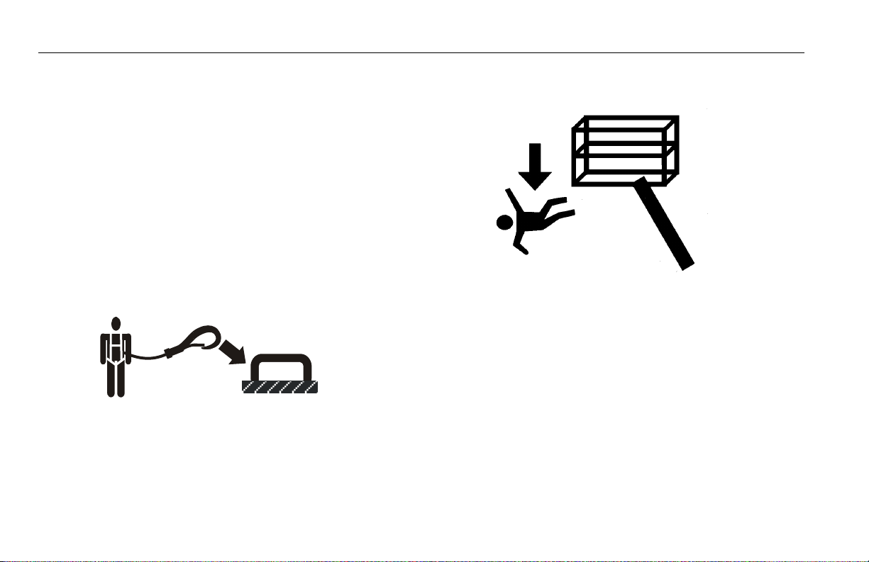
Trip and Fall Hazards
During operation, occupants in the platform must wear a full
body harness with a lanyard attached to an authorized lanyard
anchorage point. Attach only one (1) lanyard per lanyard anchorage point.
• Before operating the machine, make sure all gates are closed
and fastened in their proper position.
• Keep both feet firmly positioned on the platform floor at all
times. Do not climb on platform rails. Never use ladders, boxes,
steps, planks, or similar items on platform to provide additional reach.
• Never use the boom assembly or the trailer structure to enter
or leave the platform.
• Use extreme caution when entering or leaving platform. Be
sure that the boom is telescoped out and fully lowered. Face
the machine, maintain “three point contact” with the machine,
using two hands and one foot or two feet and one hand during entry and exit.
1-4 – JLG Lift – 3121197
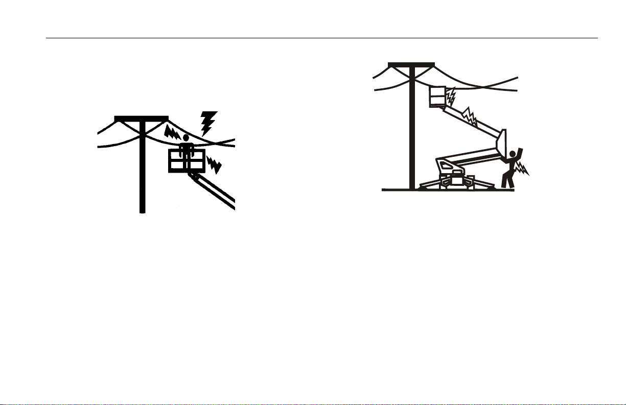
Electrocution Hazards
• This machine is not insulated and does not provide protection
from contact or proximity to electrical current.
SECTION 1 - SAFETY
• Maintain safe distance from electrical lines, apparatus, or any
energized (exposed or insulated) parts according to the Minimum Approach Distance (MAD) as shown in Table 1-1.
• Allow for machine movement and electrical line swaying.
3121197 – JLG Lift – 1-5
SECTION 1 - SAFETY
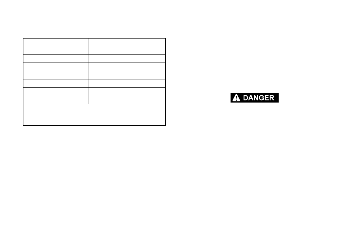
Table 1-1. Minimum Approach Distances (M.A.D.)
Voltage Range
(Phase to Phase)
0 to 50 KV 10 (3)
Over 50KV to 200 KV 15 (5)
Over 200 KV to 350 KV 20 (6)
Over 350 KV to 500 KV 25 (8)
Over 500 KV to 750 KV 35 (11)
Over 750 KV to 1000 KV 45 (14)
NOTE: This requirement shall apply except where
employer, local or governmental regulations are
more stringent.
• Maintain a clearance of at least 10 ft. (3m) between any part of
the machine and its occupants, their tools, and their equipment
from any electrical line or apparatus carrying up to 50,000 volts.
One foot additional clearance is required for every additional
30,000 volts or less.
MINIMUM APPROACH DISTANCE
in Feet (Meters)
• The minimum approach distance may be reduced if insulating
barriers are installed to prevent contact, and the barriers are rated
for the voltage of the line being guarded. These barriers shall not
be part of (or attached to) the machine. The minimum approach
distance shall be reduced to a distance within the designed working dimensions of the insulating barrier. This determination shall
be made by a qualified person in accordance with the employer,
local, or governmental requirements for work practices near
energized equipment
DO NOT MANEUVER MACHINE OR PERSONNEL INSIDE PROHIBITED ZONE (MSAD).
ASSUME ALL ELECTRICAL PARTS AND WIRING ARE ENERGIZED UNLESS KNOWN OTHERWISE.
1-6 – JLG Lift – 3121197
SECTION 1 - SAFETY
Tipping Hazards
• The user should be familiar with the surface before operating.
Do not exceed the allowable sideslope and grade while operating.
• Do not elevate platform while on a soft surface.
• Before operating on floors, bridges, trucks, and other surfaces,
check allowable capacity of the surfaces.
• Never exceed the maximum platform capacity. Distribute
loads evenly on platform floor.
• Do not raise the platform unless the machine is on firm surfaces and outriggers are properly set.
• Keep the chassis and outriggers of the machine at least 2 ft.
(0.6m) from holes, bumps, drop-offs, obstructions, debris, concealed holes, and other potential hazards on the floor/surface.
• Do not push or pull any object with the boom.
• Never attempt to use the machine as a crane with platform
attached. Do not tie-off machine to any adjacent structure.
• Do not operate the machine when wind conditions exceed 28
mph (12.5 m/s).
• Do not increase the surface area of the platform or the load.
Increase of the area exposed to the wind will decrease stability
and could result in a tip-over.
• Do not increase the platform size with unauthorized platform
extensions or attachments.
• If boom assembly or platform is in a position that one or more
outriggers are off the ground, all persons must be removed
before attempting to stabilize the machine. Use cranes, forklift
trucks, or other appropriate equipment to stabilize machine.
3121197 – JLG Lift – 1-7

SECTION 1 - SAFETY
Crushing and Collision Hazards
• Approved head gear must be worn by all operating and
ground personnel.
• Check work area for clearances overhead, on sides, and bottom of platform when lifting or lowering platform, and driving.
• During operation, keep all body parts inside platform railing.
• Always post a lookout when driving in areas where vision is
obstructed.
• Keep non-operating personnel at least 6 ft. (1.8m) away from
machine during all operations.
• Under all travel conditions, the operator must limit travel
speed according to conditions of ground surface, congestion,
visibility, slope, location of personnel, and other factors causing hazards of collision or injury to personnel.
• Exercise extreme caution at all times to prevent obstacles from
striking or interfering with operating controls and persons in
the platform.
• Be sure that operators of other overhead and floor level
machines are aware of the aerial work platform’s presence. Disconnect power to overhead cranes.
• Warn personnel not to work, stand, or walk under a raised
boom or platform. Position barricades on floor if necessary.
1-8 – JLG Lift – 3121197

SECTION 1 - SAFETY
1.5 LIFTING, AND HAULING
• Never allow personnel in platform while towing, lifting, or
hauling the machine.
• Ensure boom is in the stowed position and the transportation
latch is locked prior to towing, lifting or hauling. The platform
must be completely empty.
• When lifting machine, lift only at designated areas of the
machine. Lift the unit with equipment of adequate capacity.
• Refer to the Machine Operation section of this manual for lifting information.
1.6 TOWING HAZARDS
Safe and proper usage of the trailer mounted boom lift is essential to avoid accidents. Unsafe use; separation of trailer mounted
boom lift from tow vehicle or loss of control of the trailer
mounted boom lift or trailer/tow vehicle combination could
result in death or serious injury. Common causes for trailer accidents include:
a. Driving too fast for conditions;
b. Failure to adjust handling while towing a trailer;
c. Trailer improperly coupled to the hitch;
d. Incorrect use of safety chains;
e. Incorrect use of breakaway brake;
f. Mismatch of trailer and hitch;
g. Unsafe tires, lug nuts or wheels;
h. Inoperable brakes, lights or mirrors;
i. Modifying the trailer;
j. Inadequate tow vehicle or towing hitch; and
k. Not properly maintaining the trailer structure.
1.7 ADDITIONAL HAZARDS / SAFETY
• Do not use machine as a ground for welding.
• When performing welding or metal cutting operations, precautions must be taken to protect the chassis from direct
exposure to weld and metal cutting spatter.
• Do not refuel the machine with the engine running.
• Battery fluid is highly corrosive. Avoid contact with skin and
clothing at all times.
• Charge batteries only in a well ventilated area.
3121197 – JLG Lift – 1-9

SECTION 1 - SAFETY
DO NOT OPERATE THE MACHINE WHEN WIND CONDITIONS EXCEED 28 MPH (12.5 M/
S).
Table 1-2. Beaufort Scale (For Reference Only)
Beaufort
Number
0 0 0-0.2 Calm Calm. Smoke rises vertically.
1 1-3 0.3-1.5 Light air Wind motion visible in smoke.
2 4-7 1.6-3.3 Light breeze Wind felt on exposed skin. Leaves rustle.
3 8-12 3.4-5.4 Gentle breeze Leaves and smaller twigs in constant motion.
4 13-18 5.5-7.9 Moderate breeze Dust and loose paper raised. Small branches be gin to move.
5 19-24 8.0-10.7 Fresh breeze Smaller trees sway.
6 25-31 10.8-13.8 Strong breeze Large branches in motion. Whistling heard in overhead wires. Umbrella use
7 32-38 13.9-17.1 Near Gale/Moderate Gale Whole trees in motion. Effort needed to walk against the wind.
8 39-46 17.2-20.7 Fresh Gale Twigs broken from trees. Cars veer on road.
9 47-54 20.8-24.4 Strong Gale Light structure damage.
Wind Speed
mph m/s
Description Land Conditions
becomes difficult.
1-10 – JLG Lift – 3121197

SECTION 2 - USER RESPONSIBILITIES, MACHINE PREPARATION, AND INSPECTION
SECTION 2. USER RESPONSIBILITIES, MACHINE PREPARATION, AND INSPECTION
2.1 PERSONNEL TRAINING
The aerial platform is a personnel handling device; so it is necessary that it be operated and maintained only by trained personnel.
Persons under the influence of drugs or alcohol or who are subject to seizures, dizziness or loss of physical control must not
operate this machine.
Operator Training
Operator training must cover:
1. Use and limitations of the controls in the platform and at the
ground, emergency controls and safety systems.
2. Control labels, instructions, and warnings on the machine.
3. Rules of the employer and government regulations.
4. Use of approved fall protection device.
5. Enough knowledge of the mechanical operation of the
machine to recognize a malfunction or potential malfunction.
6. The safest means to operate the machine where overhead
obstructions, other moving equipment, and obstacles,
depressions, holes, drop-offs.
7. Means to avoid the hazards of unprotected electrical conductors.
8. Specific job requirements or machine application.
Training Supervision
Training must be done under the supervision of a qualified person in an open area free of obstructions until the trainee has
developed the ability to safely control and operate the machine.
Operator Responsibility
The operator must be instructed that he/she has the responsibility and authority to shut down the machine in case of a malfunction or other unsafe condition of either the machine or the job
site.
3121197 – JLG Lift – 2-1

SECTION 2 - USER RESPONSIBILITIES, MACHINE PREPARATION, AND INSPECTION
2.2 PREPARATION, INSPECTION, AND MAINTENANCE
The following table covers the periodic machine inspections and
maintenance required by JLG Industries, Inc. Consult local regulations for further requirements for aerial work platforms. The frequency of inspections and maintenance must be increased as
necessary when the machine is used in a harsh or hostile environment, if the machine is used with increased frequency, or if the
machine is used in a severe manner.
JLG INDUSTRIES, INC. RECOGNIZES A FACTORY-QUALIFIED SERVICE TECHNICIAN AS A
PERSON WHO HAS SUCCESSFULLY COMPLETED THE JLG SERVICE TRAINING SCHOOL
FOR THE SPECIFIC JLG PRODUCT MODEL.
2-2 – JLG Lift – 3121197

SECTION 2 - USER RESPONSIBILITIES, MACHINE PREPARATION, AND INSPECTION
Table 2-1.Inspection and Maintenance Table
Type Freq uenc y
Pre-Start Inspection Before using each day; or
whenever there’s an Operator change.
Pre-Delivery Inspect ion (See Note) Before each sale, lease, or rental delivery. Owner, Dealer, or User Qualified JLG Mechanic Service and Maintenance Manual
Frequent Inspection In service for 3 months or 1 50 hours, whichever comes first;
o r
Out of service for a period of more than 3 months;
o r
Purchase d used.
Annual Machine Inspection Annually, no later than 13 months from the date of prior
inspection.
Preventative Maintenance At intervals as specified in the Service and Maintenance
Manual.
NOTE: Inspection forms are available from JLG. Use the Service and Maintenance Manual to perform inspections.
Primary
Responsibility
User or Operator User or Operator Operator and Safety Manual
Owner, Dealer, or User Q ualified JLG Mechanic Service and Maintenance Manual
Owner, Dealer, or User Factory Qualified
Owner, Dealer, or User Q ualified JLG Mechanic Service and Maintenance Manual
Service
Qualification
Service Technician
(Recommended)
Reference
and applicable JLG inspection form
and applicable JLG inspection form
Service and Maintenance Manual
and applicable JLG inspection form
3121197 – JLG Lift – 2-3
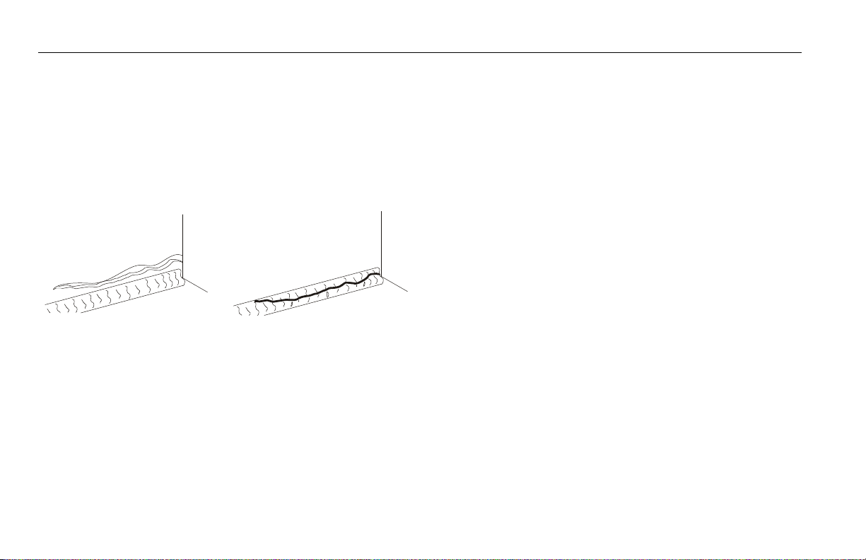
SECTION 2 - USER RESPONSIBILITIES, MACHINE PREPARATION, AND INSPECTION
Paren t Met al Cr ack
Wel d Cr ac k
Pre-Start Inspection
The Pre-Start Inspection should include each of the following:
1. Cleanliness – Check all surfaces for leakage (oil, fuel, or battery fluid) or foreign objects. Report any leakage to the
proper maintenance personnel.
2. Structure - Inspect the machine structure for dents, damage, weld or parent metal cracks or other discrepancies.
3. Decals and Placards – Check all for cleanliness and legibility. Make sure none of the decals and placards are missing.
Make sure all illegible decals and placards are cleaned or
replaced.
4. Operation and Safety Manuals – Make sure a copy of the
Operator and Safety Manual, AEM Safety Manual (ANSI markets only), and ANSI Manual of Responsibilities (ANSI markets only) is enclosed in the weather resistant storage
container.
5. “Walk-Around” Inspection – Refer to Figure 2-3.
6. Battery – Charge as required.
7. Fuel (Combustion Engine Powered Machines) – Add the
proper fuel as necessary.
8. Engine Oil Supply - Ensure the engine oil level is at the Full
mark on the dipstick and the filler cap is secure.
9. Hydraulic Oil – Check the hydraulic oil level. Ensure hydraulic oil is added as required.
10. Accessories/Attachments - Reference the Operator and
Safety Manual of each attachment or accessory installed
upon the machine for specific inspection, operation, and
maintenance instructions.
11. Function Check – Once the “Walk-Around” Inspection is
complete, perform a functional check of all systems in an
area free of overhead and ground level obstructions. Refer to
Section 4 for more specific operating instructions.
2-4 – JLG Lift – 3121197

SECTION 2 - USER RESPONSIBILITIES, MACHINE PREPARATION, AND INSPECTION
IF THE MACHINE DOES NOT OPERATE PROPERLY, TURN OFF THE MACHINE IMMEDIATELY! REPORT THE PROBLEM TO THE PROPER MAINTENANCE PERSONNEL. DO NOT
OPERATE THE MACHINE UNTIL IT IS DECLARED SAFE FOR OPERATION.
Function Check
Perform the Function Check as follows:
1. From the ground control console with no load in the platform:
a. Check that all guards protecting the function control
switches and controllers are in place;
b. Operate all functions;
c. Ensure that all machine functions are disabled when
the Emergency Stop Button is pushed in.
d. Ensure all boom functions stop when the function
enable switch is released.
2. With the platform in the stowed position:
a. Check that telescope out and lift up above horizontal
are disabled with the outriggers retracted and the
boom out of transport position.
3. From the platform control console:
a. Ensure that the control console is firmly secured in the
proper location;
b. Check that all guards protecting the function control
switches and controllers are in place;
c. Operate all functions;
d. Ensure all boom functions stop when the function
enable switch is released.
e. Ensure that all machine functions are disabled when
the Emergency Stop Button is pushed in.
3121197 – JLG Lift – 2-5

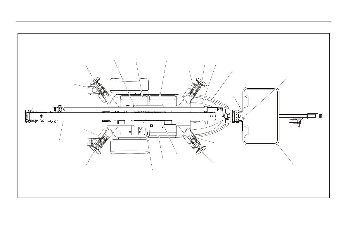
SECTION 2 - USER RESPONSIBILITIES, MACHINE PREPARATION, AND INSPECTION
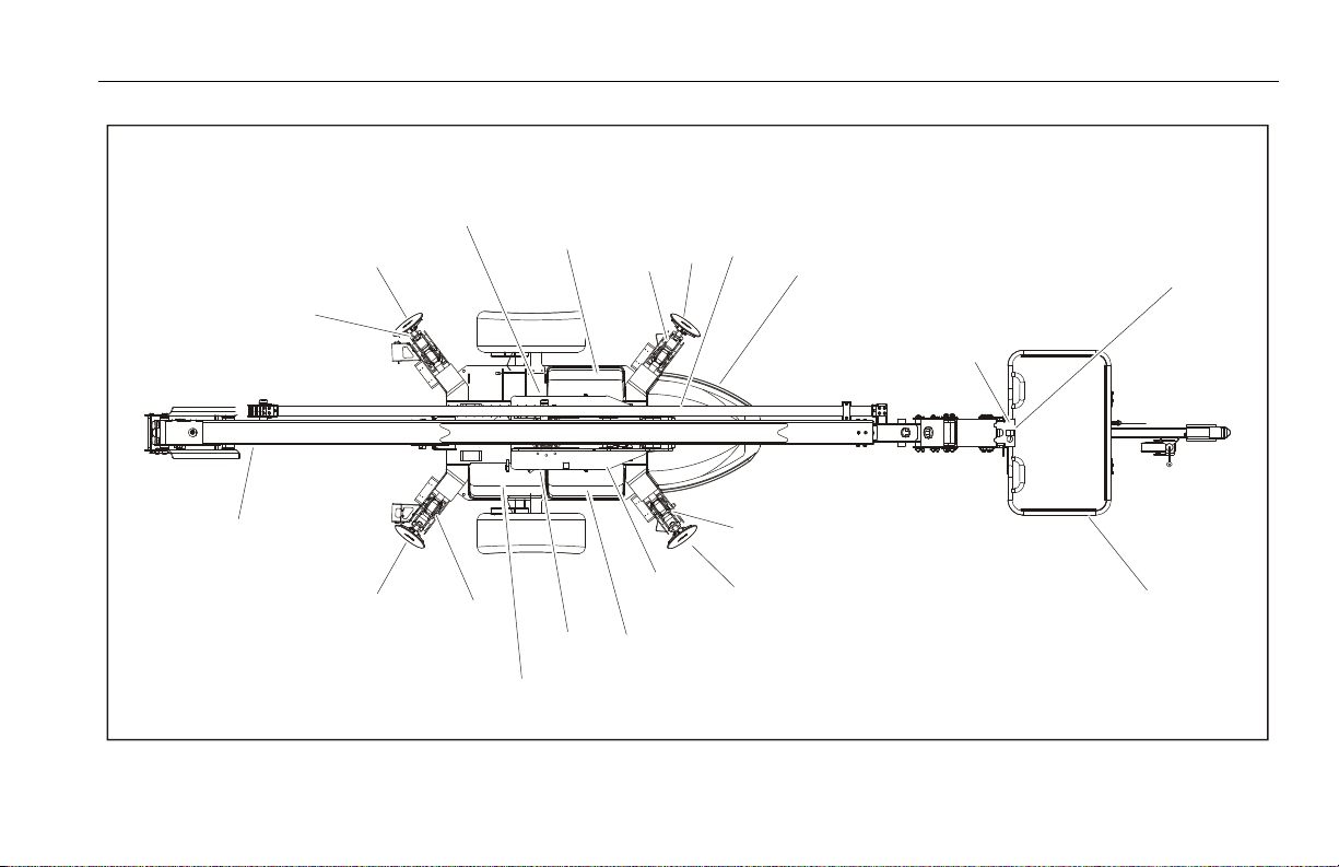
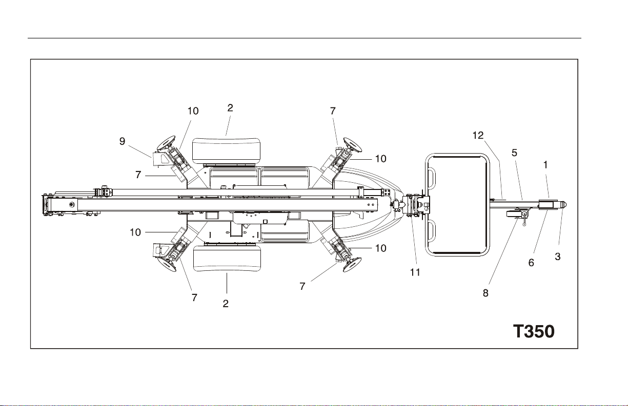
Figure 2-1. Basic Nomenclature
1. C ou p le r
2. S a fe t y C h ai n s ( N /A o n C E & Au st r al i a n S p ec )
3. To ng u e J a ck
4. Pa r ki n g Br a ke
5. O u tr i gg e r
6. C ha s si s
7. Tu r nt ab l e
8. L ow er B o om
9. U pr i gh t
10. Boom
11. Platform
12. Platform Console
2-6 – JLG Lift – 3121197

SECTION 2 - USER RESPONSIBILITIES, MACHINE PREPARATION, AND INSPECTION
This page left blank intentionally.
3121197 – JLG Lift – 2-7
SECTION 2 - USER RESPONSIBILITIES, MACHINE PREPARATION, AND INSPECTION
1
2
2
3
4
5
5
6
6
6
6
9
9
9
9
6
7
8
5
5
T350
Figure 2-2. Daily Walk-Around Inspection - Sheet 1 of 3
2-8 – JLG Lift – 3121197
SECTION 2 - USER RESPONSIBILITIES, MACHINE PREPARATION, AND INSPECTION
T500J
1
2
2
3
4
5
5
6
6
6
6
6
7
8
9
9
9
9
5
5
Figure 2-3. Daily Walk-Around Inspection - Sheet 2 of 3
3121197 – JLG Lift – 2-9

SECTION 2 - USER RESPONSIBILITIES, MACHINE PREPARATION, AND INSPECTION
General
Begin the "Walk-Around Inspection" at Item 1, as noted on the
diagram. Continue checking each item in sequence for the
conditions listed in the following checklist.
TO AVOID POSSIBLE INJURY, BE SURE MACHINE POWER IS OFF.
DO NOT OPERATE MACHINE UNTIL ALL MALFUNCTIONS HAVE BEEN CORRECTED.
INSPECTION NOTE: On all components, make sure there are no
loose or missing parts, that they are securely fastened, and no visible damage, leaks or excessive wear exists in addition to any
other criteria mentioned.
1. Platform Assembly and Gate - See Inspection Note;
access drop bar slides freely. Platform retention pin properly installed and locked.
2. Platform & Ground Control Consoles - Switches and
levers return to neutral, decals/placards secure and legible, control markings legible.
3. Boom Sections/Turntable - See Inspection Note.
4. Swing Drive & Turntable Bearing- No evidence of dam-
age. Evidence of proper lubrication. No evidence of loose
bolts or looseness between bearing and machine.
5. Cover Assemblies - See Inspection Note.
6. All Hydraulic Cylinders - No visible damage; pivot pins
and hydraulic hoses undamaged, not leaking.
7. Main Hydraulic Pump - See Inspection Note.
8. Platform Rotator (If Equipped) - See Inspection Note.
9. Outriggers - See Inspection Note; pads pivot freely.
Figure 2-4. Daily Walk-Around Inspection - Sheet 3 of 3
2-10 – JLG Lift – 3121197

SECTION 3. TOWING
SECTION 3 - TOWING
3.1 GENERAL TOWING INFORMATION
DO NOT MOVE THE TRAILER UNTIL THE TRAILER IS PROPERLY HITCHED TO THE TOW
VEHICLE AND THE TRAILER JACK IS FULLY RETRACTED.
3.2 COUPLER
The trailer is equipped with a ball hitch coupler that is suitable for
the size and weight of the trailer. The load rating of the coupler
and the necessary ball size are listed on the trailer tongue. Do not
change the coupler to a smaller size.
3.3 TOW VEHICLE AND HITCH INFORMATION
IF THE VEHICLE OR HITCH IS NOT PROPERLY SELECTED AND MATCHED TO THE GROSS
VEHICLE WEIGHT RATING (GVWR) OF YOUR TRAILER, YOU CAN CAUSE AN ACCIDENT
THAT COULD LEAD TO DEATH OR SERIOUS INJURY.
Towing Hitch
The towing hitch attached to your tow vehicle must have a
capacity equal to or greater than the load rating of the trailer you
intend to tow. The hitch capacity must also be matched to the
tow vehicle capacity.
3.4 COUPLING AND UNCOUPLING THE TRAILER
THE TRAILER MUST BE PROPERLY AND SECURELY COUPLED TO THE HITCH OF THE
TOW VEHICLE. UNCOUPLING OF THE TRAILER DURING TRANSPORT COULD RESULT IN
DEATH OR SERIOUS INJURY.
Before Coupling the Trailer to Tow Vehicle
1. Wipe the hitch ball clean and inspect it visually and by feel
for flat spots, cracks and pits.
2. Ensure boom is stowed with platform over hitch. Secure the
boom with the transport latch.
3. Push in the Emergency Stop at Platform Controls.
4. Push in the Emergency Stop at Ground Controls. Position
Platform/Ground Select switch to center OFF.
5. Remove loose items from the platform.
3121197 – JLG Lift – 3-1

SECTION 3 - TOWING
Tongue Height
Proper tongue height is critical to maintaining stability during
towing. The trailer should always be as level as possible while
towing. Due to varying vehicle height, the coupling height may
need adjusted with a raised or dropped ball mount.
THE TRAILER TONGUE MUST BE LEVEL BEFORE TOWING. ADJUST THE COUPLER OR
TOW VEHICLE HITCH TO ACHIEVE THIS HEIGHT.
Coupler and Ball
The coupler on the trailer connects to the ball attached to the
hitch on the tow vehicle. Before each tow, coat the ball with a thin
layer of automotive bearing grease to reduce wear and ensure
proper operation; and check the locking device that secures the
coupler to the ball for proper operation.
If you see or feel evidence of wear, such as flat spots, deformations, pitting or corrosion, on the ball or coupler, immediately
have your dealer inspect them to determine the proper action to
prevent possible failure of the ball and coupler system. All bent or
broken coupler parts must be replaced before towing the trailer.
The coupler must operate properly and automatically snap into
the latched position. Oil the pivot points, sliding surfaces, and
spring ends with SAE 30W motor oil. Keep the ball pocket and
latch mechanism clean. Dirt or contamination can prevent proper
operation of the latching mechanism.
When replacing a ball, the load rating must match or exceed the
GVWR of the trailer.
Tongue Jack
NOTE: To avoid damaging the handle while trailering in the horizontal
position, secure the handle to the jack with a bungee cord or
rope.
The jack is designed to be swiveled into a horizontal or storage
position. In both the vertical and horizontal positions, the
plunger must be securely positioned in the mating hole in the
mounting bracket. To place the jack into the horizontal position,
allow about 2" (5 cm) of ground clearance beneath the wheels.
Pull the plunger pin out of the opening and swivel the jack.
Rotate either left or right until the plunger pin snaps into the
proper mounting bracket hole.
3-2 – JLG Lift – 3121197

SECTION 3 - TOWING
Coupling the Trailer to the Hitch
Lubricate the hitch ball and the inside of the coupler with a thin
layer of automotive bearing grease before each tow to reduce
wear and ensure proper operation. If your trailer is equipped with
a tongue jack, raise the coupler above the ball height.
1. Wipe the inside and outside of the coupler clean and inspect
it visually for cracks and deformations; feel the inside of the
coupler for worn spots and pits.
Be sure the coupler is tight to the tongue of the trailer. All
coupler fasteners must be visibly solid against the trailer
frame.
2. Raise the bottom surface of the coupler to be above the top
of the hitch ball by using the tongue jack.
3. Once the hitch on the trailer is open, align the tow vehicle up
with the trailer hitch.
4. Using the tongue jack, lower the entire weight of the trailer
on to the ball hitch of the tow vehicle.
5. Insert the pin into the hole behind the collar to lock the collar into place.
6. Disengage the parking brake.
7. Be sure the coupler is all the way on the hitch ball and the
collar/locking mechanism is engaged. A properly engaged
locking mechanism will allow the coupler to raise the rear of
the tow vehicle. Using the tongue jack, test to see that you
can raise the rear of the tow vehicle by 1 inch (2.5 cm), after
the coupler is locked to the hitch.
OVERLOADING CAN DAMAGE THE TONGUE JACK. DO NOT USE THE TONGUE JACK TO
RAISE THE TOW VEHICLE MORE THAN 1 INCH (2.5 CM).
NOTE: If the coupler cannot be secured to the hitch ball, do not tow the
trailer.
8. Retract the tongue jack until it is fully retracted and stow.
Uncoupling the Trailer from the Hitch
Follow these steps to uncouple your trailer from the tow vehicle:
1. Engage the parking brake.
2. Disconnect the electrical connector.
3. Disconnect the breakaway brake switch cable. For an electric
breakaway break system, promptly replace the pull pin in
the switchbox.
4. Disconnect the safety chains from the tow vehicle.
3121197 – JLG Lift – 3-3

SECTION 3 - TOWING
5. Unlock the coupler and open it.
6. Before extending the tongue jack, make certain the ground
surface below the jack pad will support the tongue load.
7. Rotate the jack handle (or crank) clockwise. This will slowly
extend the tongue jack and transfer the weight of the trailer
tongue to the jack.
Rigging Safety Chains (If equipped)
Visually inspect the safety chains and hooks for wear or damage.
Replace worn or damaged safety chains and hooks before towing.
Rig the safety chains so that they:
a. Cross each other underneath the coupler
b. Loop around a frame member of the tow vehicle or to
holes provided in the hitch system (DO NOT attach
them to an interchangeable part of the hitch assembly)
c. Have enough slack to permit tight turns, but not be
close to the road surface, so if the trailer uncouples, the
safety chains can hold the tongue up above the road.
Testing Breakaway Brake
If the coupler or hitch fails, a properly connected and working
breakaway brake system will apply electric brakes on the trailer.
The safety chains will keep the tow vehicle attached and as the
brakes are applied at the trailer’s axles, the trailer/tow vehicle
combination can come to a controlled stop.
ELECTRIC BRAKES
The breakaway brake system includes a battery, a switch with a
pull pin, and a breakaway brake controller. The breakaway brake
system may be fitted with a charging facility that draws power
from the tow vehicle. If the electrical system on your tow vehicle
does not provide power to the breakaway brake battery, you
must periodically charge the battery to keep the breakaway
brake system in working order.
1. Connect the pull pin cable to the tow vehicle so that the pull
pin will be pulled out before all of the slack in the safety
chains is taken up. Do not connect the pull pin cable to a
safety chain or to the hitch ball or hitch ball assembly. This
would keep the breakaway brake system from operating
when it is needed.
3-4 – JLG Lift – 3121197

SECTION 3 - TOWING
2. Remove the pull pin from the switch and test tow the trailer,
at less than 5 mph (8 kph). You should feel the trailer resisting being towed, but the wheels will not necessarily be
locked. If the brakes do not function, do not tow the trailer
until the brakes are repaired.
3. Immediately replace the pull pin. The breakaway brake system battery discharges rapidly when the pull pin is removed.
TO AVOID POSSIBLE INJURY DO NOT TOW THE TRAILER WITH THE PULL PIN REMOVED
AND THE BREAKAWAY BRAKE SYSTEM ON BECAUSE THE BRAKES WILL OVERHEAT
WHICH CAN RESULT IN PERMANENT BRAKE FAILURE.
If you do not use your trailer for three or more months, or during
winter months:
a. Store the battery indoors; and
b. Charge the battery every three months.
Replace the breakaway brake battery according to the intervals
specified by the battery manufacturer.
HYDRAULIC BRAKES
The breakaway brake system includes a cable attached to an activation lever. Read and follow the instructions here as well as the
instructions that have been prepared by the breakaway brake
controller manufacturer.
Connect the breakaway cable to the tow vehicle so that the activation lever will be pulled before all of the slack in the safety
chains is taken up. Do not connect the breakaway cable to a
safety chain or to the hitch ball or hitch ball assembly. This would
keep the breakaway brake system from operating when it is
needed.
Manually pull the activation lever and test tow the trailer, at less
than 5 mph (8 kph). You should feel the trailer resisting being
towed, but the wheels will not necessarily be locked. If the brakes
do not function, do not tow the trailer until the brakes are
repaired.
Reset the activation lever prior to towing.
3121197 – JLG Lift – 3-5

SECTION 3 - TOWING
CONNECT THE BREAKAWAY CABLE TO THE TOW VEHICLE; AND NOT TO THE HITCH,
BALL OR SUPPORT. BEFORE TOWING THE TRAILER, TEST THE FUNCTION OF THE
BREAKAWAY BRAKE SYSTEM. IF THE BREAKAWAY BRAKE SYSTEM IS NOT WORKING,
DO NOT TOW THE TRAILER. HAVE IT SERVICED OR REPAIRED.
NOTE: Do not tow the trailer with the breakaway brake system ON
because the brakes will overheat which can result in permanent
brake failure.
If your trailer has electric brakes, your tow vehicle must have an
electric brake controller that sends power to the trailer brakes.
Before towing the trailer on the road, you must operate the brake
controller while trying to pull the trailer in order to confirm that
the electric brakes operate. While towing the trailer at less than 5
mph (8 kph), manually operate the electric brake controller in the
tow vehicle cab. You should feel the operation of the trailer
brakes.
Connect the Electrical Cables
Connect the trailer lights to the tow vehicle's electrical system
using the electrical connectors.
Check all lights for proper operation:
a. Clearance and Running Lights (Turn on tow vehicle
headlights).
b. Brake Lights (Step on tow vehicle brake pedal).
c. Turn Signals (Operate tow vehicle directional signal
lever).
d. Backup Lights (Put tow vehicle gear shift into reverse).
Check electric brakes (if equipped) for proper operation.
BEFORE EACH TOW CHECK THAT THE TAILLIGHTS, BRAKE LIGHTS AND TURN SIGNALS
WORK. CHECK THAT THE ELECTRIC BRAKES WORK BY OPERATING THE BRAKE CONTROLLER INSIDE THE TOW VEHICLE.
3-6 – JLG Lift – 3121197

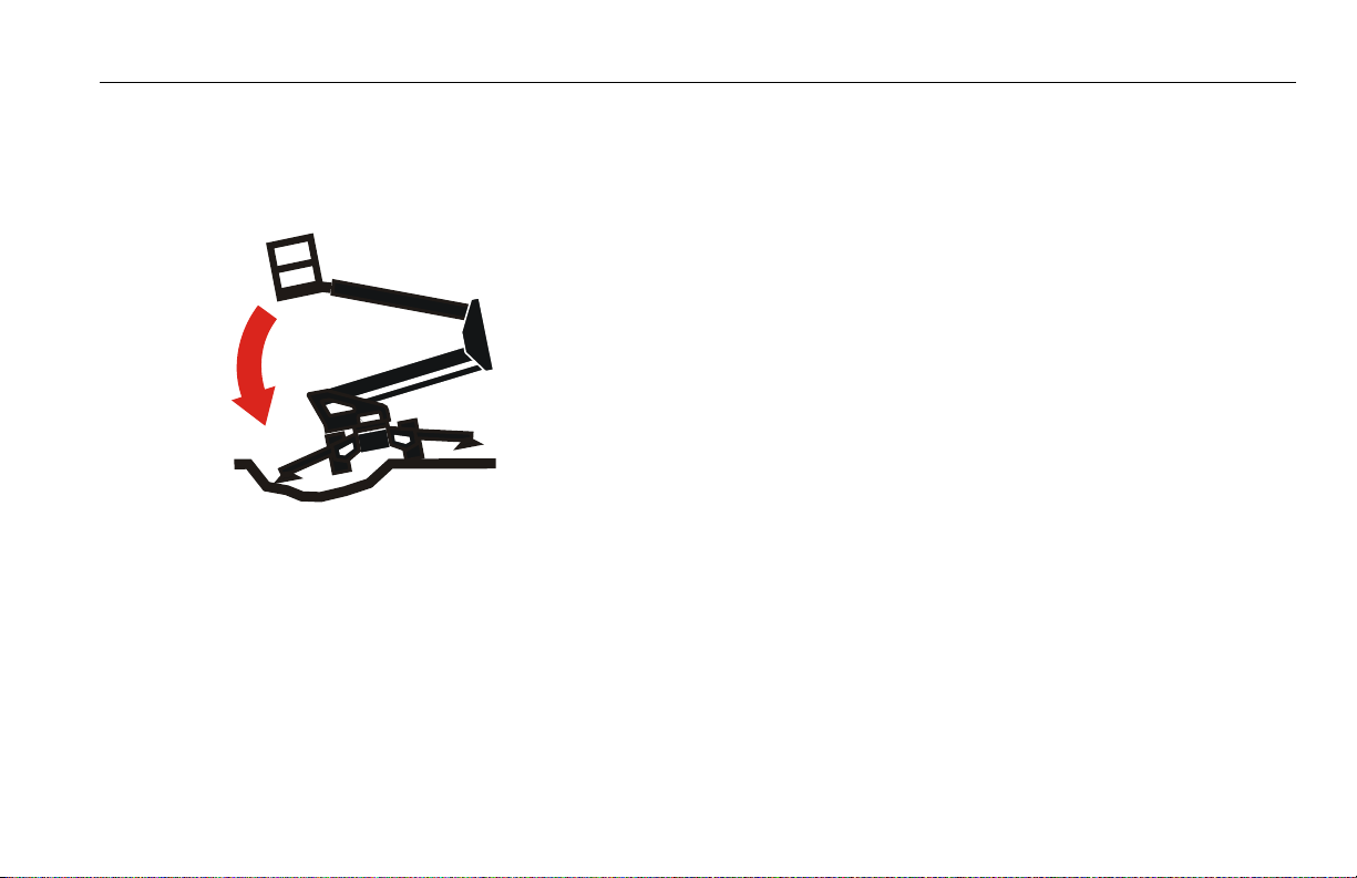
SECTION 3 - TOWING
DO NOT TOW IF LOCK-OUT
LEVER IS ENGAGED
LIFT LEVER TAB TO
ENGAGE LOCKOUT
3.5 ENGAGING MANUAL LOCKOUT LEVER
NOTE: These instructions are applicable on machines S/N 0030002099
to Present.
The manual lockout lever is used to control the brake pressure
being applied to the trailer when backing up. Having the actuator
in the extended position will make it easier to engage the lockout
lever. To engage the lockout lever, move the lever back and
upwards until the front of the lever nests into the round spacer as
shown below. This will prohibit movement of the actuator when
backing up. The lockout lever will move to the towing position
when you drive forward again.
3.6 TRAILER MANEUVERING
The hazards and risks of injury are also much greater than when
driving without a trailer. Driving a vehicle with a trailer in tow is
different from driving without a trailer in tow. Acceleration,
maneuverability and braking, are all lessened with a trailer in tow.
Spend time adjusting to the different feel and maneuverability of
the tow vehicle with a trailer.
3.7 TOWING GUIDELINES
• Before towing, check coupling, safety chain, safety brake,
tires, wheels and lights.
• Check the lug nuts or bolts for tightness.
• Check coupler tightness after towing 50 miles (80.5 km).
• If equipped with electric brakes, adjust the brake controller to engage the trailer brakes before the tow vehicle
brakes.
• Be aware of the width of the trailer. This is important when
turning, passing, and pulling next to a curb.
• Be aware of the height of the trailer, especially when
approaching roofed areas and around trees.
3121197 – JLG Lift – 3-7

SECTION 3 - TOWING
• Be sure your rear view mirrors are adjusted properly. Use
your mirrors to verify that you have room to change lanes
or pull into traffic.
• Use your turn signals well in advance.
• Increase speed slowly when starting the tow. Carefully
watch the trailer and if you observe any trailer sway, stop
and reposition the load.
• Allow plenty of stopping space for your trailer and tow
vehicle.
• Do not drive so fast that the trailer begins to sway due to
speed. Never drive faster than 65 m.p.h. (105 kph).
• Allow plenty of room for passing. Passing distance with a
trailer is 4 times the passing distance without a trailer.
• Shift your automatic transmission into a lower gear for city
driving.
• Use lower gears for climbing and descending grades.
• Do not ride the brakes while descending grades.
• Slow down for bumps in the road. Take your foot off the
brake when crossing the bump.
• Do not apply the brakes to correct extreme trailer swaying.
Continued pulling of the trailer, and even slight acceleration, will provide a stabilizing force.
• Make regular stops after every 50 miles (80.5 km) or about
once each hour. Confirm that:
a. The coupler is secure to the hitch and is locked
b. Electrical connectors are connected
c. There is appropriate slack in the safety chains
d. There is appropriate slack in the breakaway switch
cable
e. The tires are not visibly low on pressure
3-8 – JLG Lift – 3121197

SECTION 3 - TOWING
3.8 PRE-TOW INSPECTION
See Figure 3-1. and Figure 3-2.
Prior to each tow, a Pre-Tow Inspection must be performed.
Check each item as specified in the checklist below.
TO AVOID POSSIBLE INJURY, BE SURE MACHINE POWER IS OFF.
DO NOT TOW MACHINE UNTIL ALL MALFUNCTIONS HAVE BEEN CORRECTED.
INSPECTION NOTE: On all components, make sure there are no
loose or missing parts, that they are securely fastened, and no visible
damage, leaks or excessive wear exists in addition to any other criteria mentioned.
1. Brakes - Reservoir level full (hydraulic brakes only). Proper
operation and adjustment.
2. Wheel and Tires - Properly secured, no missing lug nuts,
proper inflation. Refer to Section 7.4, Tires & Wheels. Inspect
wheels for damage and corrosion.
3. Trailer Coupler - Secured, locked, and in proper operating
condition.
4. Tow Vehicle Coupler Ball (Not Shown) - Secured and in
proper operating condition. Rock the hitch ball in all directions to make sure it is tight to the hitch, and visually check
that the hitch ball nut is solid against the lock washer and
hitch frame.
5. Safety Chains - Check that the chains are properly rigged to
tow vehicle, not to detachable hitch components.
6. Emergency Breakaway Cables - Check that the cables are
properly rigged to tow vehicle, not to detachable hitch components.
7. Lights and Signals - Check clearance lights, tail lights, stop
lights, turn signals, and backup lights for proper operation.
Replace or repair inoperative lights.
8. Tongue Jack - Retracted and stowed.
9. License Plate - Secured to mounting
10. Leveling Jacks - See inspection note.
11. Stow Latch - Properly secured.
12. Parking Brake - released.
OBSERVE ALL LOCAL AND NATIONAL MOTOR VEHICLE REGULATIONS PERTAINING TO
THE OPERATION OF TRAILERS.
3121197 – JLG Lift – 3-9
SECTION 3 - TOWING
Figure 3-1. Pre-Tow Inspection - Sheet 1 of 2
3-10 – JLG Lift – 3121197

SECTION 3 - TOWING
Figure 3-2. Pre-Tow Inspection - Sheet 2 of 2
3121197 – JLG Lift – 3-11

SECTION 3 - TOWING
NOTES:
3-12 – JLG Lift – 3121197

SECTION 4 - MACHINE CONTROLS AND INDICATORS
SECTION 4. MACHINE CONTROLS AND INDICATORS
4.1 GENERAL
THE MANUFACTURER HAS NO DIRECT CONTROL OVER MACHINE APPLICATION AND
OPERATION. THE USER AND OPERATOR ARE RESPONSIBLE FOR CONFORMING WITH
GOOD SAFETY PRACTICES.
NOTE: On all battery powered machines:
If at any time during operation the machine is idle for a period
exceeding 30 minutes, the emergency stop switch(es) must be
recycled to start the machine again.
This section provides the necessary information needed to
understand control functions.
4.2 CONTROLS AND INDICATORS
NOTE: All machines are equipped with control panels that use symbols
to indicate control functions.
NOTE: The indicator panels use different shaped symbols to alert the
operator to different types of operational situations that could
arise. The meaning of those symbols are explained below.
Indicates a potentially hazardous situation, which if
not corrected, could result in serious injury or death.
This indicator will be red.
Indicates an abnormal operating condition, which if
not corrected, may result in machine interruption or
damage. This indicator will be yellow.
Indicates important information regarding the operating condition, i.e. procedures essential for safe operation. This indicator will be green with the exception of
the capacity indicator which will be green or yellow
depending upon platform position.
3121197 – JLG Lift – 4-1
SECTION 4 - MACHINE CONTROLS AND INDICATORS
TO AVOID SERIOUS INJURY, DO NOT OPERATE MACHINE IF ANY CONTROL LEVERS OR
TOGGLE SWITCHES CONTROLLING PLATFORM MOVEMENT DO NOT RETURN TO THE
OFF POSITION WHEN RELEASED.
NOTE: When Power/Emergency Stop switch is in the “ON” position and
engine is not running, an alarm will sound, indicating Ignition is
“ON”.
Ground Control Station
See Figure 4-1., Ground Control Station
NOTE: The Function Enable switch must be held down in
order to operate Boom Telescope, Lift, Swing, Jib
Lift, and Platform Level Override.
1. Engine Start (if equipped)
To start the engine, the start switch must be pushed in until
the engine starts.
2. Engine Choke (if equipped)
When starting a cold engine, the choke switch must be
pushed in (along with the engine start switch) until the
engine starts.
WHEN THE MACHINE IS SHUT DOWN THE MASTER/EMERGENCY STOP SWITCH MUST
BE POSITIONED TO THE “OFF” POSITION TO PREVENT DRAINING THE BATTERY.
3. Power/Emergency Stop Switch
A two-position red mushroom shaped switch supplies
power to PLATFORM/GROUND SELECT switch when pulled
out (on). When pushed in (off), power is shut off to the PLATFORM/GROUND SELECT switch.
4. Boom Telescope Control
Provides extension and retraction of the boom.
5. Lift Control
Provides raising and lowering of the boom.
6. Jib Lift (if equipped)
Provides raising and lowering of the jib.
4-2 – JLG Lift – 3121197

SECTION 4 - MACHINE CONTROLS AND INDICATORS
Figure 4-1. Ground Control Station
1. S ta r t
2. C ho k e
3. P ow er / Em e rg e nc y St o p
4. Te le s co p e
5. L i ft
6. J ib L i ft
7. P la t fo r m L e ve l
8. S ys t em D is t re s s
9. Outrigger Indicator
10. Outrigger Control
11. Swing
12. Function Enable
13. Platform Ground Select
14. Hourmeter
3121197 – JLG Lift – 4-3

SECTION 4 - MACHINE CONTROLS AND INDICATORS
9. Outrigger Indicators
ONLY USE THE PLATFORM LEVELING OVERRIDE FUNCTION FOR SLIGHT LEVELING OF
THE PLATFORM. INCORRECT USE COULD CAUSE THE LOAD/OCCUPANT TO SHIFT OR
FALL. FAILURE TO DO SO COULD RESULT IN DEATH OR SERIOUS INJURY.
7. Platform Leveling Override
A three position switch allows the operator to adjust the
automatic self leveling system. This switch is used to adjust
platform level in situations such as ascending/descending a
grade.
8. System Distress Indicator
The light indicates that the JLG Control System has detected
a malfunction and a Diagnostic Trouble Code has been set in
the system memory. Refer to the Service Manual for instructions concerning the trouble codes and trouble code
retrieval.
The malfunction indicator light will illuminate for 2-3 seconds when the key is positioned to the on position to act as
a self test.
Each individual outrigger indicator will illuminate to show
its’ respective outrigger is properly deployed.
10. Outrigger Control
Allows the operator to raise or lower the outriggers.
11. Swing Control
Provides 410° non-continuous turntable rotation.
12. Function Enable.
The switch must be held to the right to enable all
boom controls.
4-4 – JLG Lift – 3121197

SECTION 4 - MACHINE CONTROLS AND INDICATORS
13. Platform/Ground Select Switch
A three position, key operated switch supplies power to the
platform control console when positioned to PLATFORM.
With the switch key in the GROUND position, power is shut
off to platform and only ground controls are operable.
NOTE: With PLATFORM/GROUND SELECT switch in the center position,
power is shut off to controls at both operating stations.
14. Hourmeter
Registers the amount of time the machine has been in use.
On electric machines, all functions when motion is commanded are recorded. On engine powered machines, by
connecting into the oil pressure circuit of the engine, only
engine run hours are recorded.
Platform Station
See Figure 4-2., Platform Control Console - Standard Machine and Figure 4-3., Platform Control Console w/Drive & Set Option
TO AVOID SERIOUS INJURY, DO NOT OPERATE MACHINE IF ANY CONTROL LEVERS OR
TOGGLE SWITCHES CONTROLLING PLATFORM MOVEMENT DO NOT RETURN TO THE
OFF OR NEUTRAL POSITION WHEN RELEASED.
1. Power/Emergency Stop
A two-position red mushroom shaped switch supplies
power to PLATFORM Controls when pulled out (on). The
switch must be twisted clockwise to pull it out.
When pushed in (off), power is shut off to the platform controls.
Within about 2 seconds of pulling the switch out, the
machine will perform a diagnostic check of the various electrical circuits, and if everything is functioning correctly, the
platform alarm will beep once. During this time the lights on
the indicator panel will also blink once as a bulb check.
3121197 – JLG Lift – 4-5

SECTION 4 - MACHINE CONTROLS AND INDICATORS
2. Engine Choke (if equipped)
Engages engine choke.
3. Function Selector
Selects the function (Platform Level, Lift, Swing, Jib Lift, Telescope) that is controlled by the function controller.
4. Enable Indicator
The enable indicator shows that the controls are enabled. If a
function is not selected within seven seconds, or a seven
second lapse between ending one function and beginning
the next function occurs, the enable light will go out.
5. Outrigger Set Indicator
Indicates the outriggers are properly set.
6. System Distress Indicator
The light indicates that the JLG Control System has detected
a malfunction and a Diagnostic Trouble Code has been set in
the system memory. Refer to Section 5.8, User Fault Codes or
the Service Manual for instructions concerning the trouble
codes and trouble code retrieval.
The malfunction indicator light will illuminate for 2-3 seconds when the key is positioned to the on position to act as
a self test.
7. Battery Level Indicator (Electric Machines Only)
Indicates the charge level of the battery.
4-6 – JLG Lift – 3121197

SECTION 4 - MACHINE CONTROLS AND INDICATORS
Figure 4-2. Platform Control Console - Standard Machine
1. P ow er / Em e rg e nc y St o p
2. C ho k e ( E ng i ne Po w er ed )
3. F un c t io n Se l ec t or
4. E na b l e I n di c at or
5. Outrigger Set Indicator
6. System Distress Indicator
7. B at t er y L ev el I n di c at or
8. T il t Al a rm Wa r ni n g L i gh t
9. F un c t io n En a bl e
10. Not Used
11. Function Controller
12. Start
3121197 – JLG Lift – 4-7

SECTION 4 - MACHINE CONTROLS AND INDICATORS
Figure 4-3. Platform Control Console w/Drive & Set Option
1. Po w er / Em e rg e nc y St o p
2. C ho k e ( E ng i ne Po w er ed )
3. F un c t io n Se l ec t or
4. E na b le I nd i c at or
5. O u tr i gg e r S e t I n di c at o r
6. S ys t em D is t re s s I n di c at o r
7. B at t er y Le v el I nd i c at or
8. T il t Al a rm Wa r ni n g L i gh t
9. F un c t io n En a bl e
10. Drive & Set /Outrigger Enable Button
11. Function Controller
12. Start
4-8 – JLG Lift – 3121197

SECTION 4 - MACHINE CONTROLS AND INDICATORS
8. Tilt Alarm Warning Indicator
IF ILLUMINATED WHEN BOOM IS RAISED OR EXTENDED, RETRACT AND LOWER TO
BELOW HORIZONTAL THEN REPOSITION MACHINE SO THAT IT IS LEVEL BEFORE
EXTENDING BOOM OR RAISING BOOM FROM THE TRANSPORT POSITION.
Indicates that the chassis is out of level (over 2° on CE spec
machines; 2.5° on ANSI spec machines). If the boom is out of
the stowed position and the chassis is out of level, an audible alarm will sound.
9. Function Enable
To operate any function, the enable switch must be activated and the function selected within seven seconds. If a
function is not selected within seven seconds, or if a seven
second lapse between ending one function and beginning
the next function, the enable light will go out and the
enable switch must be released and depressed again to
enable the controls.
Releasing the enable switch removes power from all controls.
10. Drive & Set/Outrigger Enable Button
Pushing the button enables the Drive & Set or Outrigger
function depending upon the position of the Function
Selector.
3121197 – JLG Lift – 4-9

SECTION 4 - MACHINE CONTROLS AND INDICATORS
11. Function Controller
Controls boom functions (Platform Level, Lift, Swing, Jib Lift,
Telescope, Outriggers, Drive, and Steer) depending upon the
position of the Function Selector Switch.
12. Engine Start (if equipped).
To start the engine, the switch must be pushed in until the
engine starts.
4-10 – JLG Lift – 3121197

SECTION 5. MACHINE OPERATION
SECTION 5 - MACHINE OPERATION
5.1 DESCRIPTION
This machine is a towable hydraulic personnel lift equipped with
a work platform on the end of an elevating and rotating boom.
The primary operator control station is in the platform. The operator can raise or lower the main or tower boom or swing the
boom to the left or right. Standard boom swing is 410° non-continuous left and right of the stowed position. The machine has a
Ground Control Station which will override the Platform Control
Station. Ground Controls operate Boom Lift and Swing, and are to
be used in an emergency to lower the platform to the ground
should the operator in the platform be unable to do so.
5.2 BOOM OPERATING CHARACTERISTICS AND LIMITATIONS
Capacities
The boom can be raised from the transport position with or without any load in platform, if:
1. Machine is positioned on a firm surface and outriggers are
set properly.
2. Machine is not coupled to tow vehicle.
3. Load is within manufacturer’s rated capacity.
4. All machine systems are functioning properly.
5. Machine is as originally equipped from JLG.
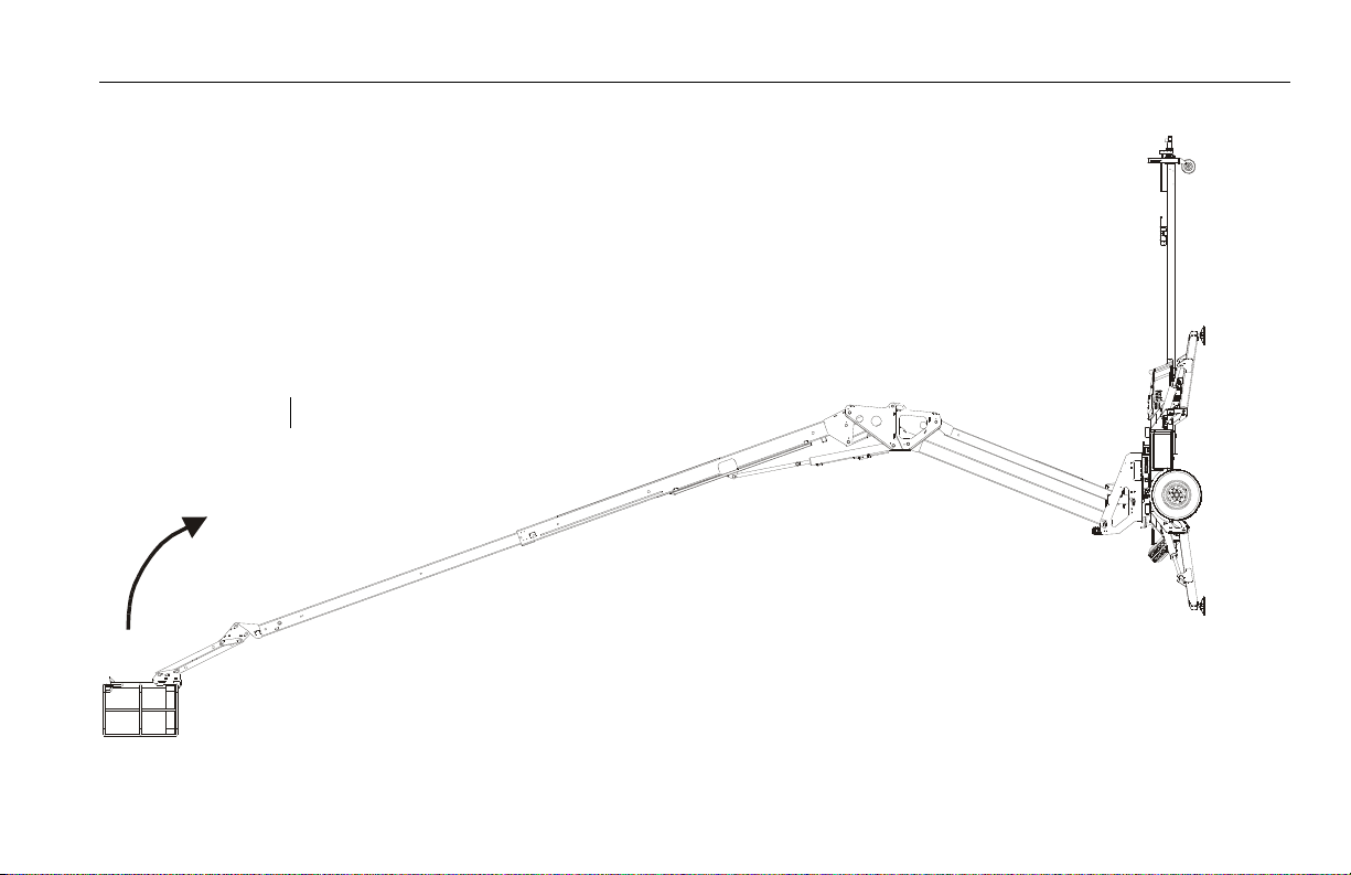
Stability
Machine stability is based on two (2) conditions which are called
FORWARD and BACKWARD stability. The machine’s position of
least FORWARD stability is shown in (See Figure 5-1.), and its position of least BACKWARD stability is shown in (See Figure 5-2.)
TO AVOID FORWARD OR BACKWARD TIPPING, DO NOT OVERLOAD MACHINE OR OPERATE THE MACHINE ON AN OUT-OF-LEVEL SURFACE.
3121197 – JLG Lift – 5-1

SECTION 5 - MACHINE OPERATION
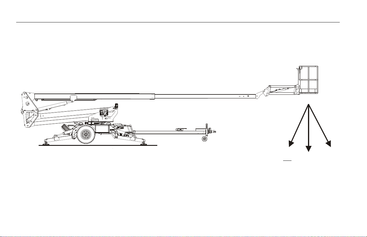
Figure 5-1. Position of Least Forward Stability (T350)
MACHINE WILL
TIP OVER IN
DIRECTION OF ARROWS IF OVERLOADED
MAIN BOOM FULLY EXTENDED AND
HORIZONTAL
TURNTABLE ROTATED
90 DEGREES FROM
STOWED POSITION
TOWER RAISED ENOUGH TO GET MAIN BOOM TO HORI-
ZONTAL
5-2 – JLG Lift – 3121197

SECTION 5 - MACHINE OPERATION
Figure 5-2. Position of Least Backward Stability (T350)
MACHINE WILL
TIP OVER IN
DIRECTION OF ARROW IF OVERLOADED
MAIN BOOM
FULLY ELEVATED
TURNTABLE ROTATED
90 DEGREES FROM
STOWED POSITION
.
3121197 – JLG Lift – 5-3
SECTION 5 - MACHINE OPERATION
TOWER RAISED ENOUGH TO GET MAIN BOOM TO HORI-
ZONTAL
MACHINE WILL
TIP OVER IN
DIRECTION OF ARROWS IF OVERLOADED
MAIN BOOM FULLY EXTENDED AND
HORIZONTAL
JIB HORIZONTAL
TURNTABLE IN
STOWED POSITION
Figure 5-3. Position of Least Forward Stability (T500J)
5-4 – JLG Lift – 3121197
SECTION 5 - MACHINE OPERATION
MACHINE WILL TIP OVER IN
DIRECTION OF ARROW IF OVER-
LOAD ED
MAIN BOOM
FULLY ELEVATED
TURNTABLE ROTATED 180° FROM
STOWED POSITION
JIB FULLY
ELEVATED
Figure 5-4. Position of Least Backward Stability (T500J)
3121197 – JLG Lift – 5-5

SECTION 5 - MACHINE OPERATION
5.3 ENGINE OPERATION (IF EQUIPPED)
NOTE: Initial starting should always be performed from the Ground
Control console.
Starting Procedure
IF ENGINE FAILS TO START PROMPTLY, DO NOT CRANK FOR AN EXTENDED TIME.
SHOULD ENGINE FAIL TO START AGAIN, ALLOW STARTER TO “COOL OFF” FOR 2-3 MINUTES. IF ENGINE FAILS AFTER SEVERAL ATTEMPTS, REFER TO ENGINE MAINTENANCE
MANUAL.
1. Turn key of SELECT switch to GROUND. Position POWER/
EMERGENCY STOP switch to ON, then push the ENGINE
START switch until engine starts.
When starting a cold engine, the choke switch must be
pushed in (along with the engine start switch) until the
engine starts.
ALLOW ENGINE TO WARM-UP FOR A FEW MINUTES AT LOW SPEED BEFORE APPLYING
ANY LOAD.
2. After engine has had sufficient time to warm up, shut engine
off.
3. Turn SELECT switch to PLATFORM.
4. From Platform, pull POWER/EMERGENCY STOP switch out,
then push the ENGINE START switch until engine starts.
Shutdown Procedure
1. Remove all load and allow engine to operate at low speed
for 3-5 minutes; this allows further reduction of internal
engine temperature.
2. Push POWER/EMERGENCY STOP switch in.
3. Turn MASTER switch to Off.
Refer to Engine Manufacturer’s manual for detailed information.
5-6 – JLG Lift – 3121197

SECTION 5 - MACHINE OPERATION
Fuel Valve Lever
NOTE: The fuel valve is turned off upon delivery and must be turned on
prior to use. The fuel valve should be turned off when machine is
not being used.
The fuel valve lever must be in the ON position for the engine to
run. When the engine is not in use, leave the fuel valve lever in
the OFF position to prevent carburetor flooding and to reduce
the possibility of fuel leakage.
5.4 OUTRIGGERS
THE OUTRIGGERS MUST BE SET BEFORE LIFTING CAN BEGIN.
ALWAYS UNHITCH FROM TOW VEHICLE PRIOR TO OPERATING OUTRIGGERS.
From the Ground Console
1. Position the Platform/Ground Select switch to ground control.
2. Engage and hold the function enable switch together with
the outrigger control switch.
3. The lift is equipped with auto-level. When the lift reaches
level an alarm will sound with three short beeps indicating
that the lift is level. If the auto-level system does not operate
properly, DO NOT operate the machine; have the system
repaired by a qualified service technician.
3121197 – JLG Lift – 5-7

SECTION 5 - MACHINE OPERATION
From the Platform Console (Drive & Set Only)
1. Turn and hold select switch to outrigger position, push and
hold the Drive & Set/Outrigger Enable button, squeeze the
enable trigger and then move controller in the desired direction to set all the outriggers.
2. The lift is equipped with auto-level. When the lift reaches
level an alarm will sound with three short beeps indicating
that the lift is level. If the auto-level system does not operate
properly, DO NOT operate the machine; have the system
repaired by a qualified service technician.
5.5 PLATFORM
Platform Level Adjustment
NOTE: During normal operation of the machine, the platform will auto-
matically maintain it’s position.
1. To manually Level Up, turn and hold select switch to basket
level position, squeeze the enable switch and then move
controller forward until desired position is reached.
2. To manually Level Down, turn and hold select switch to basket level position, squeeze the enable switch and then move
controller backward until desired position is reached.
ONLY USE THE PLATFORM LEVELING OVERRIDE FUNCTION FOR SLIGHT LEVELING OF
THE PLATFORM. INCORRECT USE COULD CAUSE THE LOAD/OCCUPANT TO SHIFT OR
FALL. FAILURE TO DO SO COULD RESULT IN DEATH OR SERIOUS INJURY.
Platform Rotation (If Equipped)
To rotate the platform to the left or right, use the manually actuated Platform Rotator until desired position is reached.
5.6 BOOM
TO AVOID SERIOUS INJURY, DO NOT OPERATE MACHINE IF ANY CONTROL LEVER OR
TOGGLE SWITCH CONTROLLING PLATFORM MOVEMENT DOES NOT RETURN TO THE
‘OFF’ OR NEUTRAL POSITION WHEN RELEASED.
IF THE PLATFORM DOES NOT STOP WHEN A CONTROL SWITCH OR LEVER IS RELEASED,
USE EMERGENCY STOP SWITCH TO STOP THE MACHINE.
5-8 – JLG Lift – 3121197

SECTION 5 - MACHINE OPERATION
Swinging the Boom
To swing boom, use Swing control to select Right or Left direction.
WHEN SWINGING THE BOOM MAKE SURE THERE IS AMPLE ROOM FOR THE BOOM AND
UPRIGHT TO CLEAR SURROUNDING WALLS, PARTITIONS AND EQUIPMENT.
Raising and Lowering the Boom
1. To raise the boom select the Boom Control on the select
switch, squeeze the enable switch and then move the controller forward.
2. To lower the boom select the Boom Control on the select
switch, squeeze the enable switch and then move the controller backward.
Telescoping the Boom
1. To extend the boom select the Telescope Control on the
select switch, squeeze the enable switch and then move the
controller backward.
2. To retract the boom select the Telescope Control on the
select switch, squeeze the enable switch and then move the
controller forward.
3121197 – JLG Lift – 5-9

SECTION 5 - MACHINE OPERATION
5.7 JIB LIFT
1. To raise the jib select the Jib Control on the select switch,
squeeze the enable switch and then move the controller to
the right.
2. To lower the jib select the Jib Control on the select switch,
squeeze the enable switch and then move the controller to
the left.
5.8 USER FAULT CODES
A single digit fault code blinks on the Platform and the Ground
control panel to signal the operator of a procedure fault. Refer to
Table 5-1, User Fault Codes.
Table 5-1. User Fault Codes
Code Message
0 Chassis Tilt Sensor Out Of Range
Running At Creep - Material Hook Mode
1 Function Locked Out - Joystick Not Centered At Startup
Function Locked Out - Trigger Permanently Closed
Function Problem - Engine Choke Permanently Selected
Function Problem - Engine Start Permanently Selected
Function Problem - Jib Down Permanently Selected
Function Problem - Jib Up Permanently Selected
Function Problem - Level Down Permanently Selected
Function Problem - Level Up Permanently Selected
Function Problem - Lift Down Permanently Selected
Function Problem - Lift Up Permanently Selected
Function Problem - Outrigger Set Permanently Selected
Function Problem - Outrigger Stow Permanently Selected
Function Problem - Swing Left Permanently Selected
Function Problem - Swing Right Permanently Selected
Function Problem - Telescope In Permanently Selected
Function Problem - Telescope Out Permanently Selec ted
Joystick Moved But Trigger Switch Open
Trigger Closed Too Long While In Neutral
5-10 – JLG Lift – 3121197

SECTION 5 - MACHINE OPERATION
Table 5-1. User Fault Codes
Code Message
2* Drive & O/R Prevented - Operate From Platform
Drive & O/R Prevented - Place Boom On Rest
Drive & O/R Prevented - Set Hand Brake
Drive Prevented - Lift Down
Drive Prevented - Stow Outriggers
Drive Prevented - Telescope In
Lift Down Prevented - Tele In First
Lift Up & Tele Out Prevented - Tilted & Above Elevation
"Lift Up & Tele Out Prevented - Tilted, Unset,& Above Elevation "
Lift Up & Tele Out Prevented - Unset & Above Elevation
Lift Up Prevented - Check Outriggers
Lift Up Prevented - Lift Down Then Set Outriggers
Lift Up Prevented - Tilted
Model Changed - Hydraulics Suspended - Cycle EMS
Outrigger Stow Prevented - Tele In First
Outriggers Prevented - Elevated
Running At Creep - Tilted & Above Elevation
Running At Creep - Unset & Above Elevation
Tele Out Prevented - Set Ou triggers
Tele Out Prevented - Tilted
Table 5-1. User Fault Codes
Code Message
* A 2 user flash code indicates a problem with the machine set up, such as an outrigger not prop-
erly set. If this occurs while the boom is elevated, all functions will operate at a reduced speed.
Immediately return the platform to the stowed position and reposition the machine or reset the
outriggers, as required. If the problem still exists, troubleshoot with a JLG analyzer.
A 2 user flash code and tilt alarm warning indicator ac tivated at the same time indicates a potential tipping condition. If this occurs while boom is elevated, the lift up and telescope out functions will not operate. Telescope in, lift down and swing functions will operate at reduced speed.
THE BOOM MUST BE FULLY RETRACTED BEFORE LOWERING. Immediately return the platform to
the stowed position and reposition the machine or reset the outriggers, as required. If the problem still exists, troubleshoot with a JLG analyzer.
3 Battery Voltage Too High - System Shutdown
Battery Voltage Too Low - System Shutdown
No C ha r ge Sy s te m O ut p ut
4 Functions At Cutback - Power Module Current Limit
Power Module Too Hot - Please Wait
5 Battery Voltage Too High - System Shutdown
Battery Voltage Too Low - System Shutdown
Engine Not Running
9 Vehicle Requires Service
3121197 – JLG Lift – 5-11

SECTION 5 - MACHINE OPERATION
5.9 BATTERY CHARGING
NOTE: Be sure that machine is parked in a well ventilated area before
charging.
ONLY PLUG THE CHARGER INTO A PROPERLY GROUNDED OUTLET. DO NOT USE
GROUND ADAPTORS OR MODIFY PLUG. DO NOT TOUCH NON-INSULATED PORTION OF
OUTPUT CONNECTOR OR NON-INSULATED BATTERY TERMINAL.
ALWAYS DISCONNECT THE AC SUPPLY BEFORE MAKING OR BREAKING THE CONNECTIONS TO THE BATTERY.
DO NOT OPEN OR DISASSEMBLE CHARGER.
DO NOT OPERATE CHARGER IF THE AC SUPPLY CORD IS DAMAGED OR IF THE CHARGER
HAS BEEN DAMAGED IN ANY WAY.
1. The battery charger AC input plug is located at the rear of
the machine. Connect the charger AC input plug to a
grounded outlet.
If the machine is equipped with an optional generator, the
battery charger can be plugged into the generator outlet.
See Figure 5-5.
2. When powered up the charger will go through a short selftest. The battery charger lights on the Ground Control Station will flash in sequence for two seconds.
3. The batteries are fully charged when the green light on the
battery charger status panel is illuminated.
NOTE: If the charger is left plugged in, the charger will automatically
restart a complete charge cycle if the batteries voltage drops
below a minimum voltage or 30 days has elapsed.
5-12 – JLG Lift – 3121197

SECTION 5 - MACHINE OPERATION
Figure 5-5. Generator Plug Location
3121197 – JLG Lift – 5-13

SECTION 5 - MACHINE OPERATION
Battery Charger Fault Codes
(S/N 030000199 to 030000225 & S/N 030000236 to Present)
If a fault occurred during charging, the red "Fault" LED will flash
with a code corresponding to the error. Refer to the table following for the flash codes and their removal.
Table 5-10. Battery Charger Fault Codes (Delta-Q)
Flash(s) Fault Fault Removal
1 Battery voltage high Auto-recover - Indicates a high battery pack voltage
2Battery voltage low
3Charge time-out
4 Check battery Indicates the batteries could not be trickle charged up to the minimum voltage per cell level required for the charge to be started.
5 Over-temperature Auto-recover - In dicates charger has s hut down due to high internal temperature
6 QuiQ fault
Auto-recover - Indicates either a battery pack failure, battery pack not connected to charger or battery volts per cell i s less than 0.5 VDC. Check the battery pack and connections
Indicates the batteries did not charge in the allowed time. This could occur if the batteries are a larger capacity than the algorithm is intended for or if the
batteries are damaged old or in poor condition.
Indicates that the battery will not accept charge current, or an in te r na l fa u lt h as b ee n d et ec t e d i n th e ch a rg e r. T h is f au l t w i ll nearly always be set within
the first 30 seconds of operation. Once it has been determined that the batteries and connection s are not faulty and fault 6 is again displayed after interrupting AC power for at least 10 seconds, the charger must be brought to a qualified service depot.
5-14 – JLG Lift – 3121197

SECTION 5 - MACHINE OPERATION
5.11 PLATFORM REMOVAL & INSTALLATION
1. Disconnect the platform control box harness at the platform
support.
NOTE: The standard platform assembly weighs approximately 75 lbs.
(34 kg). If equipped with the optional rotator, the platform
assembly weighs approximately 150 lbs. (68 kg).
2. Remove the hitch pin and gravity pin securing the platform
assembly to the platform support and remove the platform.
3. To install the platform, repeat steps 1 and 2 in reverse order.
3121197 – JLG Lift – 5-15

SECTION 5 - MACHINE OPERATION
5.12 MATERIAL HOOK INSTALLATION
OPERATE THE MATERIAL HOOK FROM THE REMOTE CONSOLE ONLY, DO NOT USE THE
GROUND CONTROLS.
1. Disconnect the platform control box harness at the platform
support.
2. Remove the hitch pin and gravity pin securing the platform
assembly to the platform support and remove the platform.
3. Remove the material hook from the storage position on the
turntable.
4. Place the hook in position on the platform support.
5-16 – JLG Lift – 3121197

SECTION 5 - MACHINE OPERATION
5. Secure the hook in place with the gravity pin and hitch pin.
6. Remove the platform console from the platform and con-
nect the console harness to the receptacle at the hook storage area on the turntable.
5.13 MATERIAL HOOK OPERATING PRECAUTIONS
When utilizing a JLG lift equipped with a material hook the following additional precautions must be observed.
The combined weight of material and rigging equipment must
not exceed the maximum load capacity of the material hook.
Be aware of clearances above, below, and around the machine
when handling material with the material hook.
Attach a line to restrict movement of the load.
Keep slings and chains as short as possible. Excessively long
slings and chains allow the load the swing and could cause the
machine to overturn.
Do not operate the machine when wind conditions exceed 28
mph (12.5 m/s).
REMEMBER, THE MACHINE IS NOT INSULATED AND DOES NOT PROVIDE PROTECTION
FROM CONTACT WITH OR PROXIMITY TO ELECTRICAL CURRENT. MAINTAIN A SAFE
DISTANCE AND CLEARANCE FROM ELECTRICAL LINES, APPARATUS OR ANY ENERGIZED PARTS. ALLOW FOR MACHINE MOVEMENT AND ELECTRICAL LINE SWAYING.
3121197 – JLG Lift – 5-17

SECTION 5 - MACHINE OPERATION
Never drag any part of the material on the ground or use the
boom to pull sideways. The load must be freely suspended.
Keep the material hook and tethered remote control cable
stowed in the proper location when not in use.
5.14 ACCESSORY TRAY
ANY TOOL PLACED ON THE ACCESSORY TRAY MUST BE PROPERLY SECURED AND NOT
LOOSE.
The accessory tray is intended to hold tools such as a compressor,
generator, or pressure washer. Capacity of the tray is 250 lbs. (114
kg) or a weight which does not exceed the axle rating or GVW rating, whichever is less.
5.15 PANEL TRAY
WITH THE PANEL TRAY INSTALLED, THE ORIGINAL PLATFORM CAPACITY RATINGS
ARE REDUCED AS SPECIFIED IN TABLE 7-1. DO NOT EXCEED THE NEW PLATFORM
CAPACITY RATING. REFER TO THE CAPACITY DECAL LOCATED IN THE TRAY.
AN INCREASE OF THE AREA EXPOSED TO THE WIND WILL DECREASE STABILITY. LIMIT
PANEL AREA TO 32 SQ. FT. (3 SQ. M.)
1. Check for cracked welds and damage to the tray. Make sure
the tray is properly secured to the platform.
2. Check for loose nuts and bolts.
3. Check to ensure the strap is not torn or frayed.
4. Replace torn or frayed straps, bent or crushed tray parts,
missing or illegible decals.
5. When operating, make sure no personnel are beneath the
platform.
6. Remove the tray when not in use.
5-18 – JLG Lift – 3121197

Figure 5-6. Panel Tray
1. S tr a p
2. C ap a ci t y De c al
3. N am e pl a te
4. L ef t Tra y Pa ne l
5. C la m p
6. Pa d
7. R i gh t Tra y P a ne l
SECTION 5 - MACHINE OPERATION
3121197 – JLG Lift – 5-19
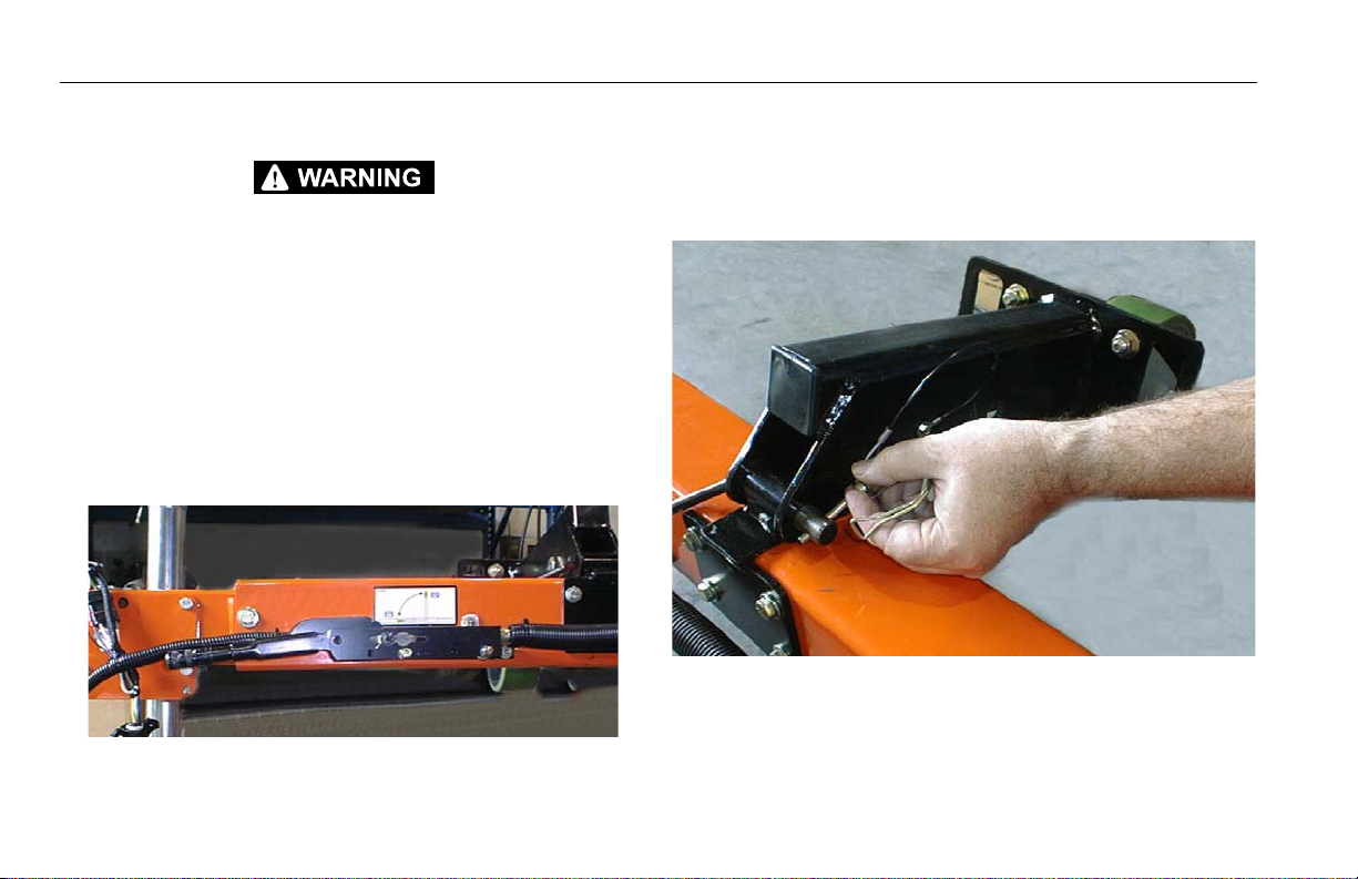
SECTION 5 - MACHINE OPERATION
5.16 DRIVE & SET
DO NOT DRIVE THE MACHINE ON GRADES OR SIDESLOPES EXCEEDING THOSE LISTED
IN TABLE 7-1.
NOTE: When the boom is raised out of the stowed position, drive will be
cut out.
To Set Up The Machine for Drive & Set Operation:
1. Place the boom in the stowed position (fully retracted, fully
lowered, over the trailer tongue).
2. Set the parking brake (ANSI brake shown). Refer to the parking brake decal on the tongue.
4. Make sure the tongue jack is extended enough to allow
installation of the jockey wheel.
5. Remove the pin securing the jockey wheel in the stowed
position and swing the wheel down into the drive position.
Secure the wheel in place with the retaining pin.
3. Release the boom latch.
5-20 – JLG Lift – 3121197

SECTION 5 - MACHINE OPERATION
3121197 – JLG Lift – 5-21

SECTION 5 - MACHINE OPERATION
Figure 5-7. Grade and Sideslope
ANSI/CSA/AUS GRADE - 20%
CE GRADE - 15%
SIDESLOPE
GRADE
ANSI/CSA/AUS SIDESLOPE - 11°
CE SIDESLOPE - 8.5°
LEVEL
5-22 – JLG Lift – 3121197

SECTION 5 - MACHINE OPERATION
6. Retract the tongue jack and swing it up into the stowed
position.
7. Properly enter the platform and start the engine.
8. Turn the function selector switch in the platform to the Drive
position.
9. Push the green Drive & Set/Outrigger Enable button at the
top of the function controller, then squeeze the function
enable trigger, then move the function controller in the
desired direction and release the green enable button.
10. Point the function controller in the desired direction of travel
to move the machine. The friction drive wheels engage
automatically when the drive function is initiated.
11. When the machine is in the desired location, set the outriggers and operate the machine.
To Prepare the Machine For Towing After Drive & Set Operation:
1. Place the boom in the stowed position.
2. Stow the outriggers.
3. Drive the machine to a firm, level, and smooth surface.
3121197 – JLG Lift – 5-23

SECTION 5 - MACHINE OPERATION
4. Lower the tongue jack and extend it enough to raise the
jockey wheel off of the ground.
5. Remove the pin securing the jockey wheel in the drive position and swing the wheel up into the stowed position.
Secure the wheel in place with the retaining pin.
5-24 – JLG Lift – 3121197
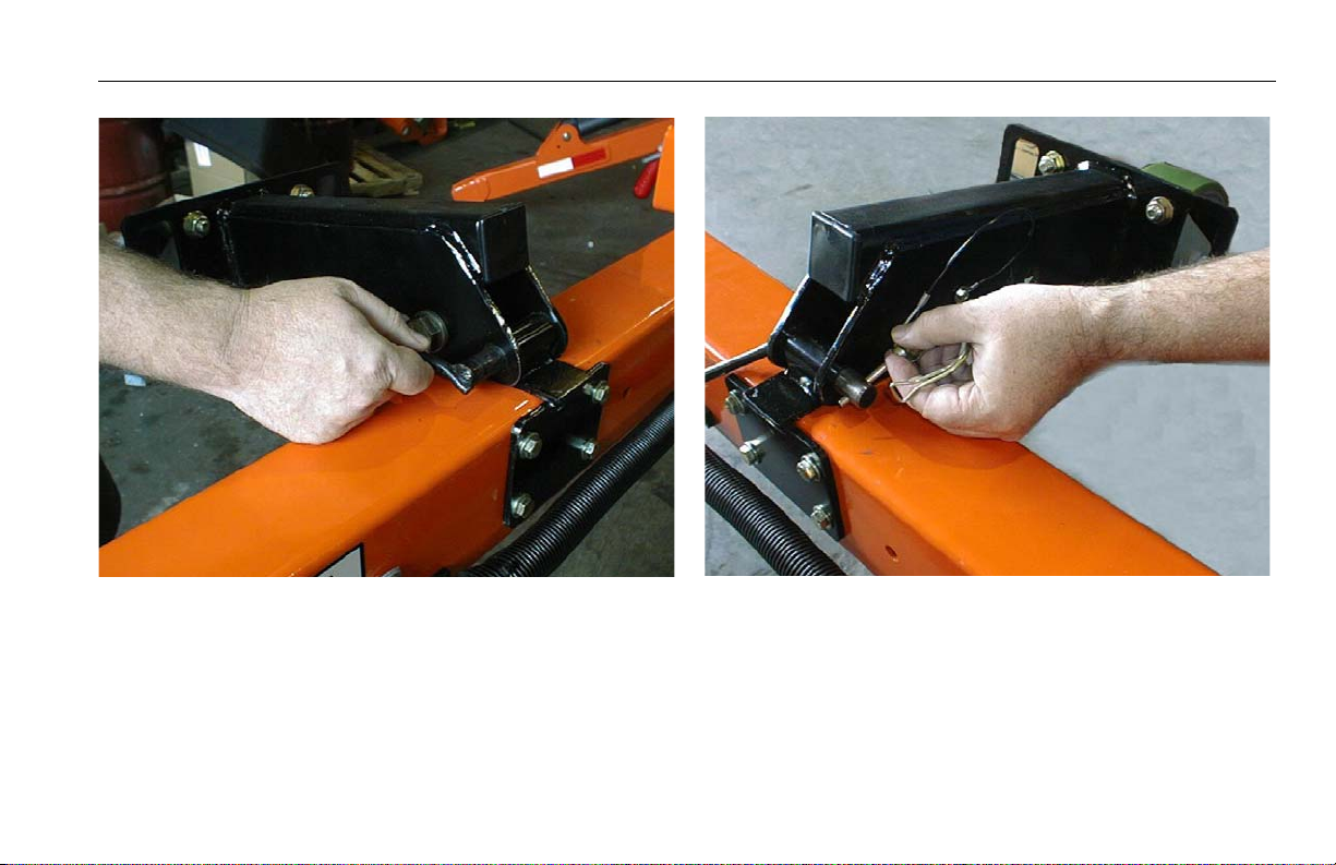
SECTION 5 - MACHINE OPERATION
3121197 – JLG Lift – 5-25

SECTION 5 - MACHINE OPERATION
6. Pull out on the drive & set control valve knob. Ensure friction
wheels are disengaged from tires.
7. The machine is now ready for towing. Refer to Section 3,
TOWING.
5.17 SHUT DOWN AND PARK
To shut down and park the machine, the procedures are as follows:
1. Transport the machine to a reasonably well protected area.
2. Ensure boom is stowed with platform over hitch. Secure the
boom with the transport latch.
3. Push in the Emergency Stop at Platform Controls.
4. Push in the Emergency Stop at Ground Controls. Position
Platform/Ground Select switch to center OFF.
5. If necessary, cover Platform Controls to protect instruction
placards, warning decals and operating controls from hostile
environment.
6. Set parking brake and uncouple from towing vehicle.
5-26 – JLG Lift – 3121197

5.18 TIE DOWN
WHEN TRANSPORTING THE MACHINE, THE BOOM MUST BE FULLY LOWERED INTO
THE BOOM REST AND TRANSPORT LATCH SECURED.
1. Place the boom in the stowed position and secure with the
transport latch.(See Figure 5-9.)
2. Remove all loose items from the machine.
3. Secure the chassis and the platform using straps or chains of
adequate strength and attached to the designated tie down
points. (See Figure 5-9.)
SECTION 5 - MACHINE OPERATION
3121197 – JLG Lift – 5-27

SECTION 5 - MACHINE OPERATION
Figure 5-8. Lifting and Tie Down Chart Prior to S/N 0030000864
5-28 – JLG Lift – 3121197

SECTION 5 - MACHINE OPERATION
Figure 5-9. Lifting and Tie Down Chart S/N 0030000864 to Present
3121197 – JLG Lift – 5-29

SECTION 5 - MACHINE OPERATION
Figure 5-10. Decal Location - ANSI (Sheet 1 of 2)
5-30 – JLG Lift – 3121197

SECTION 5 - MACHINE OPERATION
Figure 5-11. Decal Location - ANSI (Sheet 2 of 2)
3121197 – JLG Lift – 5-31

SECTION 5 - MACHINE OPERATION
Table 5-2. Decal Legend (ANSI)
Item # 0274522-L
1- -
2 1701640
3 1703814
4 1706384
5 1703817
6 1704277
7 1704412
8 1706629
9 1706372
10 1706385
11 1001131269
12 1701644
13 - -
14 - -
15 1702961
16 1704885
17 1705754
18 1706080 - T350
1706081 - T500J
Table 5-2. (Continued)Decal Legend (ANSI)
Item # 0274522-L
19 1706106
20 1706107
21 1001119637
22 1706121 - T350
1706264 - T500J
23 1706127
1706133 w/Drive
24 1706139
25 1706263
26 - -
27 1706112
28 1706128
29 1706099
30 1706111
31 1706135
32 1706386
33 1706387
34 1706108
35 1706109
36 1703813
5-32 – JLG Lift – 3121197

Table 5-2. (Continued)Decal Legend (ANSI)
Item # 0274522-L
37 to 38 - -
39 - -
40 1706337
41 1706349
42 1706440
43 - -
44 3251813
45 3760170
46 3820001
47 3820032
48 8990147
49 1705817
50 1702773
51 1705304
52 - -
SECTION 5 - MACHINE OPERATION
3121197 – JLG Lift – 5-33

SECTION 5 - MACHINE OPERATION
Figure 5-12. Decal Location - CE & Australia (Sheet 1 of 2)
5-34 – JLG Lift – 3121197

SECTION 5 - MACHINE OPERATION
Figure 5-13. Decal Location - CE & Australia (Sheet 2 of 2)
3121197 – JLG Lift – 5-35

SECTION 5 - MACHINE OPERATION
Table 5-3. Decal Legend - CE & Australia
Item # 0273631-H
1- -
2 1701640
3 1703814
4 1706384
5 1703817
6 1704277
7 1704412
8 1706120
9 1706372
10 1706393
11 1700584
12 1701644
13 - -
14 - -
15 - -
16 1705754
17 1706080 - T350
1706081 - T500J
18 - -
Table 5-3. Decal Legend - CE & Australia (Continued)
Item # 0273631-H
19 1706121 - T350
1706264 - T500J
20 1706139
21 1706314
22 1706263
23 - -
24 1706337
25 1706349
26 - -
27 1706320
28 1705670
29 1706315
30 1706317
31 1706497
32 1706440
33 3760170
34 3820001
35 3820032
36 8990147
5-36 – JLG Lift – 3121197

Table 5-3. Decal Legend - CE & Australia (Continued)
Item # 0273631-H
37 4420051
38 - -
39 - -
40 - -
SECTION 5 - MACHINE OPERATION
3121197 – JLG Lift – 5-37

SECTION 5 - MACHINE OPERATION
Figure 5-14. Decal Location - Country Specs (Sheet 1 of 2)
5-38 – JLG Lift – 3121197
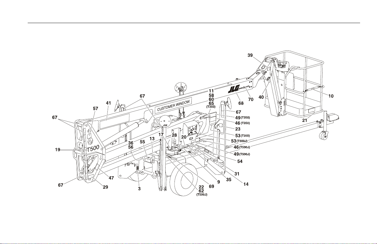
SECTION 5 - MACHINE OPERATION
Figure 5-15. Decal Location - Country Specs (Sheet 2 of 2)
3121197 – JLG Lift – 5-39

SECTION 5 - MACHINE OPERATION
Table 5-4. Decal Legend - Country Specs
ANSI Export
Item #
1- -- -- -- -
2 1701640 1701640 1701640 1701640
3 1703814 1703814 1703814 1703814
4 1706384 1706384 1706384 1706384
5 1703817 1703817 1703817 1703817
6 1704277 1704277 1704277 1704277
7 1704412 1704412 1704412 1704412
8 1706629 1706629 1706629 1706629
9 1706372 1706372 1706372 1706372
10 1706385 1706385 1706385 1706385
11 0701014 0701014 0701014 0701014
12 1001131269 1700584 1700584 1700584
13 1701644 1701644 1701644 1701644
14 - - - - - - 1702155
15- -- -- -- -
16- -- -- -- -
17 1705304 - - - - - -
French/E nglish
0273641-H
ANSI Export
Portuguese/English
0273644-H
ANSI Export
Spanish/English
0273640-H
ANSI Export
S. Africa
0274942-E
5-40 – JLG Lift – 3121197

Table 5-4. Decal Legend - Country Specs
SECTION 5 - MACHINE OPERATION
ANSI Export
Item #
18 1705754 1705754 1705754 1705754
19 1706080 - T350
20 1706106 1706106 1706106 1706106
21 1706107 1706107 1706107 1706107
22 1001119637 1001119637 - - - -
23 1706121 - T350
24
W/O Drive
Option:
With Drive
Option:
25 1706263 1706263 1706263 1706263
26- -- -- -- -
27 1706112 1706112 1706112 1706961
28 1706128 1706128 1706128 1706128
29 1706099 1706099 1706099 1706099
30 1706111 1706111 1706111 1706111
French/E nglish
0273641-H
1706081 - T500J
1706264 - T500J
0274819
0274828
ANSI Export
Portuguese/English
0273644-H
1706080 - T350
1706081 - T500J
1706121 - T350
1706264 - T500J
0274830
0274831
ANSI Export
Spanish/English
0273640-H
1706080 - T350
1706081 - T500J
1706121 - T350
1706264 - T500J
0274832
0274833
ANSI Export
S. Africa
0274942-E
1706080 - T350
1706081 - T500J
1706121 - T350
1706264 - T500J
1706127
1706133
3121197 – JLG Lift – 5-41

SECTION 5 - MACHINE OPERATION
Table 5-4. Decal Legend - Country Specs
ANSI Export
Item #
31 1706135 1706135 1706135 1706135
32 1706386 1706386 1706386 1706386
33 1706387 1706387 1706387 1706387
34 1706108 1706108 1706108 1706108
35 1706109 1706109 1706109 1706109
36 1703813 1703813 1703813 1703813
37 1706139 1706139 1706139 1706139
38- -- -- -- -
39 1706337 1706337 1706337 1706337
40 1706349 1706349 1706349 1706349
41 1706440 1706440 1706440 1706440
42
W/O Drive
Option:
With Drive
Option:
43 3251243 - - - - 3251243
44- -- -- -- -
45 1706513 1706524 1706427 - -
French/E nglish
0273641-H
0274819
0274828
ANSI Export
Portuguese/English
0273644-H
0274830
0274831
ANSI Export
Spanish/English
0273640-H
0274832
0274833
ANSI Export
S. Africa
0274942-E
- -
- -
5-42 – JLG Lift – 3121197

Table 5-4. Decal Legend - Country Specs
SECTION 5 - MACHINE OPERATION
ANSI Export
Item #
46 1706516 1706527 1706430 - -
47 1706517 1706528 1706431 - -
48 1706518 1706529 1706432 - -
49 1706519 1706530 1706433 - -
50 1706520 1706531 1706434 - -
51 1706521 1706532 1706435 - -
52 1706522 1706533 1706436 - -
53 1706523 1706534 1706437 - -
54 1706565 1706657 1706664 - -
55 1706569 1706658 1706665 - -
56 1703864 1703832 1703840 - -
57 - - 3251813 3251813 - -
58- -- -- -- -
59- -- -- -- -
60- -- -- -- -
61- -- -- -- -
62- -- -- -- -
63- -- -- -- -
French/E nglish
0273641-H
ANSI Export
Portuguese/English
0273644-H
ANSI Export
Spanish/English
0273640-H
ANSI Export
S. Africa
0274942-E
3121197 – JLG Lift – 5-43

SECTION 5 - MACHINE OPERATION
Table 5-4. Decal Legend - Country Specs
ANSI Export
Item #
64- -- -- -- -
65- -- -- -- -
66 - - 1705817 1705817 - -
67 1705817 - - - - - -
68 1702773 - - - - -
69 1706351 1706496 1706494 - -
70 1706495 - - - - - -
71- -- -- -- -
French/E nglish
0273641-H
ANSI Export
Portuguese/English
0273644-H
ANSI Export
Spanish/English
0273640-H
ANSI Export
S. Africa
0274942-E
5-44 – JLG Lift – 3121197

6.1 GENERAL
SECTION 6 - EMERGENCY PROCEDURES
SECTION 6. EMERGENCY PROCEDURES
This section explains the steps to be taken in case of an emergency situation while operating.
6.2 INCIDENT NOTIFICATION
JLG Industries, Inc. must be notified immediately of any incident
involving a JLG product. Even if no injury or property damage is
evident, the factory should be contacted by telephone and provided with all necessary details.
In USA:
JLG Phone: 877-JLG-SAFE (554-7233)
(8am till 4:45pm EST)
Outside USA:
240-420-2661
E-mail:
ProductSafety@JLG.com
Failure to notify the manufacturer of an incident involving a JLG
Industries product within 48 hours of such an occurrence may
void any warranty consideration on that particular machine.
FOLLOWING ANY ACCIDENT, THOROUGHLY INSPECT THE MACHINE AND TEST ALL
FUNCTIONS FIRST FROM THE GROUND CONTROLS, THEN FROM THE PLATFORM CONTROLS. DO NOT LIFT ABOVE 3 M (10 FT.) UNTIL YOU ARE SURE THAT ALL DAMAGE HAS
BEEN REPAIRED, IF REQUIRED, AND THAT ALL CONTROLS ARE OPERATING CORRECTLY.
6.3 EMERGENCY OPERATION
Operator Unable to Control Machine
IF THE PLATFORM OPERATOR IS PINNED, TRAPPED OR UNABLE TO
OPERATE OR CONTROL MACHINE:
1. Other personnel should operate the machine from ground
controls only as required.
2. Other qualified personnel on the platform may use the platform controls. DO NOT CONTINUE OPERATION IF CONTROLS
DO NOT FUNCTION PROPERLY.
3. Cranes, forklift trucks or other equipment can be used to
remove platform occupants and stabilize motion of the
machine.
3121197 – JLG Lift – 6-1

SECTION 6 - EMERGENCY PROCEDURES
Platform or Boom Caught Overhead
If the platform or boom becomes jammed or snagged in overhead structures or equipment, rescue platform occupants prior to
freeing the machine.
6.4 MANUAL DESCENT
The manual descent system is provided as an emergency means
to lower personnel from the platform.
NOTE: The main valve cover must be removed to access Lift and Tele-
scope manual controls.
6-2 – JLG Lift – 3121197
 Loading...