


Illustrated Parts Manual
Model
10MSP
P/N
3121229
November 1, 2013


REVISION LOG
January 1, 2006 - Original Issue Of Manual (Edited to B/M 0010680 Revision 3)
May 15, 2006 - Revised Manual (Edited to B/M 0010680 Revision 3
October 31, 2006 - Revised Manual (Edited 0010680 to Revision 6)
March 1, 2007 - Revised Manual (Edited 0010680 to Revision 7)
November 16, 2007 - Revised Manual (Edited 0010680 to Revision 10)
January 15, 2008 - Revised Manual (Edited 0010680 to Revision 10)
August 27, 2008 - Revised Manual (Edited 0010680 to Revision 11)
August 18, 2009 - Revised Manual (Edited 0010680 to Revision 12)
February 24, 2011 - Revised Manual (Edited 0010680 to Revision 13)
May 27, 2011 - Revised Manual (Edited 0010680 to Revision 13)
August 15, 2011 - Revised Manual (Edited 0010680 to Revision 14)
November 15, 2011 - Revised Manual (Edited 0010680 to Revision 14)
February 28, 2012 - Revised Manual (Edited 0010680 to Revision 14)
July 10, 2012 - Revised Manual (Edited 0010680 to Revision C)
September 28, 2012 - Revised Manual (Edited 0010680 to Revision C)
February 6, 2013 - Revised Manual (Edited 0010680 to Revision D)
May 6, 2013 - Revised Manual (Edited 0010680 to Revision D)
August 6, 2013 - Revised Manual (Edited 0010680 to Revision D)
November 1, 2013 - Revised Manual (Edited 0010680 to Revision D)
3121229 10MSP A

REVISION LOG
B 10MSP 3121229

TABLE OF CONTENTS
FIGURE NO. TITLE PAGE NO.
SECTION 1 - BASE. . . . . . . . . . . . . . . . . . . . . . . . . . . . . . . . . . . . . . . . . . . . . . . . . . . . . . . .1-1
1-1 BASE MOUNTED COMPONENTS INSTALLATION . . . . . . . . . . . . . . . . . . . . . . . . . . . 1-2
1-2 DRIVE ASSEMBLY. . . . . . . . . . . . . . . . . . . . . . . . . . . . . . . . . . . . . . . . . . . . . . . . . . . . . 1-6
1-3 COVERS AND TIE-DOWNS INSTALLATION. . . . . . . . . . . . . . . . . . . . . . . . . . . . . . . . . 1-10
SECTION 2 - CONTROLS . . . . . . . . . . . . . . . . . . . . . . . . . . . . . . . . . . . . . . . . . . . . . . . . . .2-1
2-1 PUMP MOTOR ASSEMBLY AND INSTALLATION . . . . . . . . . . . . . . . . . . . . . . . . . . . . 2-2
2-2 BATTERY CHARGER AND PLUG INSTALLATION (PRIOR TO SN 0130010886) . . . . 2-6
2-3 BATTERY CHARGER AND PLUG INSTALLATION (SN 0130010886 TO PRESENT) . . 2-8
2-4 BATTERIES, SWITCHES, HORN AND BEACON LIGHT INSTALLATION . . . . . . . . . . . 2-12
2-5 GROUND COMPONENTS INSTALLATIONS . . . . . . . . . . . . . . . . . . . . . . . . . . . . . . . . 2-16
2-6 PLATFORM CABLES AND CONTROLS INSTALLATION . . . . . . . . . . . . . . . . . . . . . . . 2-18
2-7 CONTROL BOX ASSEMBLY . . . . . . . . . . . . . . . . . . . . . . . . . . . . . . . . . . . . . . . . . . . . . 2-20
SECTION 3 - MAST . . . . . . . . . . . . . . . . . . . . . . . . . . . . . . . . . . . . . . . . . . . . . . . . . . . . . . .3-1
3-1 MAST ASSEMBLY AND INSTALLATION. . . . . . . . . . . . . . . . . . . . . . . . . . . . . . . . . . . . 3-2
SECTION 4 - PLATFORM. . . . . . . . . . . . . . . . . . . . . . . . . . . . . . . . . . . . . . . . . . . . . . . . . . .4-1
4-1 PLATFORM INSTALLATION (ALL SPECS TO PRESENT & AUSTRALIAN SPEC
PRIOR TO SN 0130018678). . . . . . . . . . . . . . . . . . . . . . . . . . . . . . . . . . . . . . . . . . . 4-2
4-2 PLATFORM INSTALLATION (AUSTRALIAN SPEC ONLY) (SN 0130018678 TO
PRESENT) . . . . . . . . . . . . . . . . . . . . . . . . . . . . . . . . . . . . . . . . . . . . . . . . . . . . . . . . 4-4
4-3 MATERIAL TRAY INSTALLATION . . . . . . . . . . . . . . . . . . . . . . . . . . . . . . . . . . . . . . . . . 4-6
4-4 OPTIONAL BICYCLE CARRIERS INSTALLATION . . . . . . . . . . . . . . . . . . . . . . . . . . . . 4-8
4-5 OPTIONAL RUG CARRIER INSTALLATION . . . . . . . . . . . . . . . . . . . . . . . . . . . . . . . . . 4-10
4-6 OPTIONAL FLUORESCENT TUBE CADDY ASSEMBLY . . . . . . . . . . . . . . . . . . . . . . . 4-12
SECTION 5 - CYLINDER . . . . . . . . . . . . . . . . . . . . . . . . . . . . . . . . . . . . . . . . . . . . . . . . . . .5-1
5-1 LIFT CYLINDER ASSEMBLY (ORIGINAL EQUIPMENT) (PRIOR TO
SN 0130011099). . . . . . . . . . . . . . . . . . . . . . . . . . . . . . . . . . . . . . . . . . . . . . . . . . . . 5-2
5-2 LIFT CYLINDER ASSEMBLY (SERVICE REPLACEMENT) (SN 0130011099 TO
PRESENT) . . . . . . . . . . . . . . . . . . . . . . . . . . . . . . . . . . . . . . . . . . . . . . . . . . . . . . . . 5-4
SECTION 6 - HYDRAULIC . . . . . . . . . . . . . . . . . . . . . . . . . . . . . . . . . . . . . . . . . . . . . . . . . .6-1
6-1 HYDRAULIC DIAGRAM . . . . . . . . . . . . . . . . . . . . . . . . . . . . . . . . . . . . . . . . . . . . . . . . . 6-2
SECTION 7 - ELECTRICAL . . . . . . . . . . . . . . . . . . . . . . . . . . . . . . . . . . . . . . . . . . . . . . . . .7-1
7-1 ELECTRICAL COMPONENTS INSTALLATION . . . . . . . . . . . . . . . . . . . . . . . . . . . . . . . 7-2
SECTION 8 - DECALS . . . . . . . . . . . . . . . . . . . . . . . . . . . . . . . . . . . . . . . . . . . . . . . . . . . . .8-1
8-1 DECAL INSTALLATION . . . . . . . . . . . . . . . . . . . . . . . . . . . . . . . . . . . . . . . . . . . . . . . . . 8-2
SECTION 9 - RECOMMENDED SERVICE PARTS STOCK . . . . . . . . . . . . . . . . . . . . . . . . . 9-1
SECTION 10 - SPECIAL OPTIONS . . . . . . . . . . . . . . . . . . . . . . . . . . . . . . . . . . . . . . . . . . .10-1
SECTION 11 - PART NUMBER INDEX . . . . . . . . . . . . . . . . . . . . . . . . . . . . . . . . . . . . . . . .11-1
3121229 10MSP i

TABLE OF CONTENTS
FIGURE NO. TITLE PAGE NO.
ii 10MSP 3121229

SECTION 1
BASE
3121229 10MSP 1-1
SECTION 1 BASE
2515
16619
3
4
4
7
17
8
9
101
107
111
102
108
103
104
110
10
11
12
13
14
18
105
201
201
203
204
204
205
205
205
205
202
20
1
FRONT
302
302
303
304
305
306
307
301
309
REAR
306
302
303
304
305
308
307
301
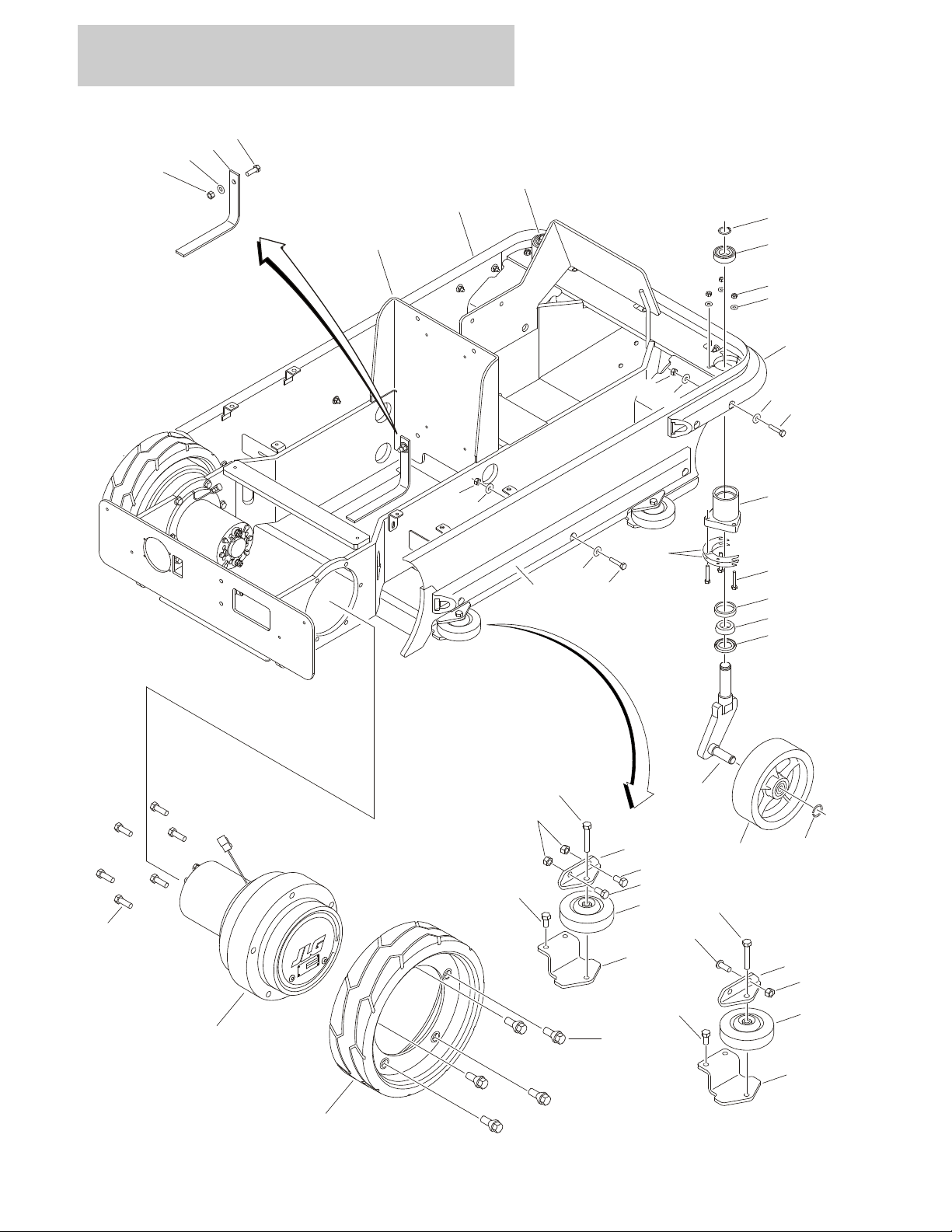
FIGURE 1-1. BASE MOUNTED COMPONENTS INSTALLATION
1-2 10MSP 3121229

SECTION 1 BASE
FIGURE 1-1. BASE MOUNTED COMPONENTS INSTALLATION
ITEM # PART NUMBER QTY. DESCRIPTION REV.
0274893 Ref BASE ASSEMBLY F
1 0100081 AR Compound, Locking
2 0274904 1 Frame Assembly (See Items 101-111 for Breakdown)
3 0630580 10 Bolt, Wheel
4 0641609 13 Bolt 3/8in-16NC x 1-1/8in
5 0940132 1 Bumper, Chassis
6 3020039 AR Lubricant Loctite #51049
7 3160323 2 Drive Motor Assembly (See Drive Assembly for Breakdown)
8 3311605 1 Locknut 3/8in-16NC
9 3760115 2 Ring, Retaining
10 3760496 2 Ring, Retaining
11 4071113 AR Shim .015in
12 4071114 AR Shim .036in
13 4240147 1 Strap, Static
14 2 Tire & Wheel Assembly Options:
Use 1001098810 Prior to SN 0130011864 (was p/n 4520281
1001098810 SN 0130011864 to Present
15 4520342 1 Spindle (Left Side)
16 4520343 1 Spindle (Right Side)
17 2 Tire & Wheel Assembly Options:
Use 1001114467 Prior to SN 0130008686 (Was p/n 4520326)
See Note SN 0130008685 to SN 0130009365 (Note: Tire & Wheel
Assemblies used in this range of SNs vary between old & new
style - Use p/n 1001114467 as replacement.)
Use 1001114467 SN 0130009366 to SN 0130011759 (was p/n 4520565)
Use1001114467 SN 0130011759 to SN 0130013970 (was p/n 1001100840)
1001114467 SN 0130013970 to Present
18 4711600 1 Flatwasher 3/8in Narrow
19 8882970 AR Coating, Clear
20 0100011 AR Locking Compound
0274904 Ref FRAME ASSEMBLY I
101 0440306 2 Bearing, Ball
102 0440307 2 Bearing, Roller
103 0440308 2 Bearing, Race
104 0641413 6 Bolt 1/4in-20NC x 1-5/8in
105 2360750 1 Frame
106 3020029 AR Grease (Not Shown)
107 3271405 6 Locknut 1/4in-20NC
108 3960590 2 Seal
109 Not Used
110 4341155 2 Mount, Caster
111 4711400 6 Flatwasher 1/4in Narrow
3121229 10MSP 1-3

SECTION 1 BASE
FIGURE 1-1. BASE MOUNTED COMPONENTS INSTALLATION (CONTINUED)
ITEM # PART NUMBER QTY. DESCRIPTION REV.
0274078 Ref BUMPERS INSTALLATION (OPTIONAL) C
201 0641408 13 Bolt 1/4in-20NC x 1in
202 0940152 2 Bumper, Side
203 0940153 1 Bumper, Front
204 3311405 13 Locknut 1/4in-20NC
205 4751400 26 Flatwasher 1/4in Wide
0240103 Ref GUIDE ROLLER ATTACHMENT (OPTIONAL) B
301 0100011 AR Locking Compound
302 0641606 10 Bolt 3/8in-16NC x 3/4in
303 0641617 4 Bolt 3/8in-16NC x 2-1/8in
304 0903120 4 Bracket, Top Roller
305 0903121 4 Bracket, Bottom Roller
306 3311605 8 Locknut 3/8in-16NC
307 4520352 4 Wheel
308 4 Hardware Options:
0641606 Bolt 3/8in-16NC x 3/4in (Prior to SN 0130015906)
3900283 Screw Button Head 3/8in-16NC x 3/4in (SN 0130015906 to
Present)
309 2 Bolt Options:
0641606 Bolt 3/8in-16NC x 3/4in (Prior to SN 0130015906)
0641609 Bolt 3/8in-16NC x 1-1/8in (SN 0130015906 to Present)
1-4 10MSP 3121229

SECTION 1 BASE
FIGURE 1-1. BASE MOUNTED COMPONENTS INSTALLATION (CONTINUED)
ITEM # PART NUMBER QTY. DESCRIPTION REV.
3121229 10MSP 1-5
SECTION 1 BASE
29
29
19
11
20
21
4
23
18
25
25
25
24
26
5
5
7
6
6
8
3
101
27
14
2
16
14
10
10
9
26
9
26
32
25
9
26
1011517
107
107
103
103A
102
106
102A
102C
204
202
201
200
205
206
207
208
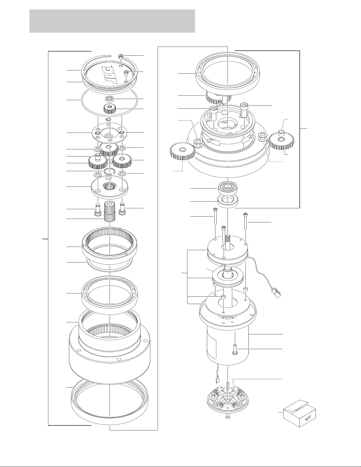
FIGURE 1-2. DRIVE ASSEMBLY
1-6 10MSP 3121229

SECTION 1 BASE
FIGURE 1-2. DRIVE ASSEMBLY
ITEM # PART NUMBER QTY. DESCRIPTION REV.
Use 3160323 Ref SPINDLE/HUB ASSEMBLY
1 Use 3160323 1 Spindle
2 Use 7024756 1 Hub
3 Use 7024758 1 Ring, Input
4 Use 70000210 1 Gear, Input Sun
5 Use 70000210 3 Gear, Input Planet
6 Use 70000210 3 Pin, Input Planet
7 Use 70000210 1 Carrier
8 Use 70000210 1 Gear, Output Sun
9 Use 70000212 3 Gear, Output Planet
10 Use 70000212 3 Pin, Output Planet
11 Use 7024747 1 Cover
12 to 13 Not Used
14 See Note 2 Bearing (Note: Use Items 201,203,205 & 206)
15 Not Used
16 See Note 1 Seal, Lip (Note: Use Items 201 & 205)
17 70000215 1 Seal, Lip
18 Use 70000210 3 Ring, Retaining
19 Use 7024747 1 Ring, Retaining
20 70000191 1 O-Ring
21 Use 7024747 1 Thrustwasher
22 Not Used
23 Use 70000210 1 Plate, Thrust
24 Use 70000210 1 Ring, Retaining
25 See Note 6 Thrustwasher (Note: Use Items 202 & 206)
26 See Note 3 Bushing, Planet (Note: Use Items 202 & 206)
27 See Note 1 Ring, Retaining (Note: Use Items 203 & 205)
29 Use 7024747 2 Plug
30 to 31 Not Used
32 Use 70000212 3 Thrustwasher, Tanged
3160323 Ref DRIVE MOTOR ASSEMBLY B
101 Use 3160323 1 Hub/Spindle Assembly (Includes Items 1-32)
102 Use 70000211 1 Electric Motor Assembly
102A Use 70000213 4 Brush
102B Use 70000213 1 Indicator, Wear (Not Shown)
102C Use 70000213 4 Spring, Brush
102D Use 70000213 1 Bearing (Not Shown)
103 Use 70000214 1 Brake Assembly
103A 70000935 1 Disc, Brake (Part of Kit)
104 to 105 Not Used
106 Use 70000211 2 Bolt
107 Use 70000214 3 Bolt
3121229 10MSP 1-7

SECTION 1 BASE
FIGURE 1-2. DRIVE ASSEMBLY (CONTINUED)
ITEM # PART NUMBER QTY. DESCRIPTION REV.
Ref KIT OPTIONS:
Repair Kit Options:
200 7024747 1 Cover Kit (Includes Items 11, 19-21 & 29)
201 7024748 1 Main Seal & Bearing Kit (Includes Items 14, 16 & 20)
202 70000210 1 Input Carrier Kit (Includes Items 4-8, 18, 20 & 23-26)
203 7024758 1 Input Ring Kit (Includes Items 3, 14, 20 & 27)
204 70000211 1 Motor Kit (Includes Items 17, 102 & 106)
205 7024756 1 Hub Kit (Includes Items 2, 14, 16, 20 & 27)
206 70000212 1 Output Planet Kit (Includes Items 9, 10, 14, 20, 25, 26 & 32)
207 70000213 1 Brush & Bearing Kit (Includes Items 102A-102D)
208 70000214 1 Brake Kit (Includes Items 103 & 107)
1-8 10MSP 3121229

SECTION 1 BASE
FIGURE 1-2. DRIVE ASSEMBLY (CONTINUED)
ITEM # PART NUMBER QTY. DESCRIPTION REV.
3121229 10MSP 1-9
SECTION 1 BASE
7
4
12
15
11815
121215516
6
101
101
102
102
103
103
104
104
111
1
9
13A
3
14
17
14
20
13B
21
OR
12
18
19
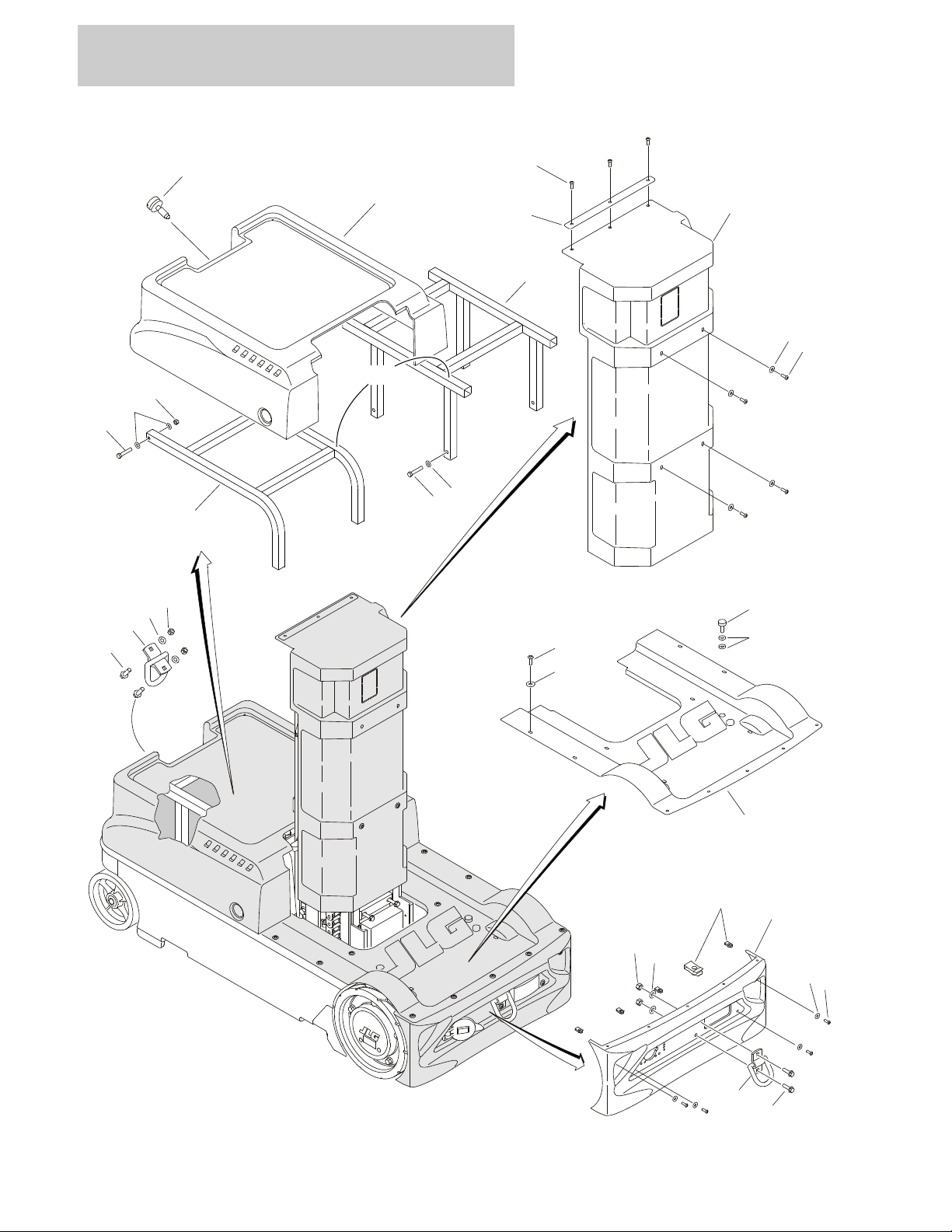
FIGURE 1-3. COVERS AND TIE-DOWNS INSTALLATION
1-10 10MSP 3121229

SECTION 1 BASE
FIGURE 1-3. COVERS AND TIE-DOWNS INSTALLATION
ITEM # PART NUMBER QTY. DESCRIPTION REV.
0274901 Ref COVER INSTALLATION C
1 0100011 AR Locking Compound
2Not Used
3 0641616 4 Bolt 3/8in-16NC x 2in (Prior to SN 0130015319)
4 0903222 1 Brace
5 0940049 2 Stopper, Hood
6 1 Cover, Battery and Frame Options:
Use 1001120531 Prior to SN 0130015319 (was p/n 1671141)
1001120531 SN 0130015319 to Present
7 1671143 1 Cover, Mast
8 1671146 1 Cover, Rear Bumper
9 1671298 1 Cover, Front Hood
10 Not Used
11 3300454 9 Nut 1/4in-20NC
12 3900258 22 Screw Button Head 1/4in-20NC x 3/4in
13 1 Support Options:
13A 4341067 Prior to SN 0130015319
13B 1001121648 SN 0130015319 to Present
14 4711600 4 Flatwasher 3/8in Narrow
15 4751400 19 Flatwasher 1/4in (Wide)
16 4751500 4 Flatwasher 5/16in (Wide)
17 1380169 1 Clip
18 3900174 1 Screw, Thumb
19 3760308 1 Retainer
20 0641617 2 Bolt 3/8in-16NC x 2-1/8in (SN 0130015319 to Present)
21 3311605 2 Locknut 3/8in-16NC (SN 0130015319 to Present)
0240114 Ref TIE-DOWNS INSTALLATION A
101 0811610 4 Screw 3/8in-16NC x 1-1/4in
102 3311605 4 Locknut 3/8in-16NC
103 3760365 2 Tie-Ring
104 4711600 4 Flatwasher 3/8in Narrow
3121229 10MSP 1-11

SECTION 1 BASE
FIGURE 1-3. COVERS AND TIE-DOWNS INSTALLATION (CONTINUED)
ITEM # PART NUMBER QTY. DESCRIPTION REV.
1-12 10MSP 3121229

SECTION 2
CONTROLS
3121229 10MSP 2-1
SECTION 2 CONTROLS
7
2J
1J
2D
102
10
9
8D
8B
8A
8C
1B
1D
2H
3F
3B
3A
3C
3D
3E
2G
2C
2A
2E
4B
4E
4C
107
4A
4D
4L
1E
2B
1A
1F
1C
1H
1G
4J
4H
5E
4G
5C
4K
5B
5D
5A
108
101
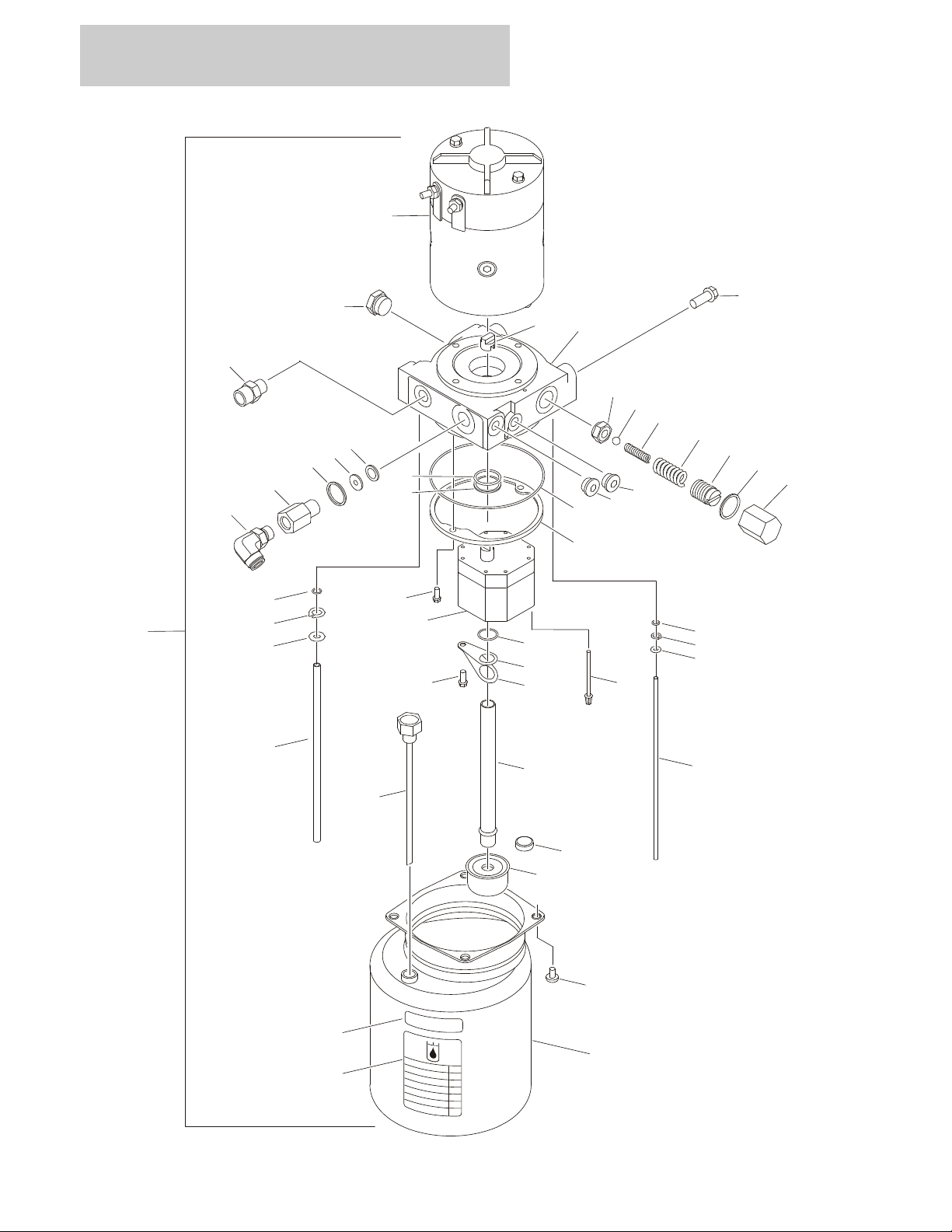
FIGURE 2-1. PUMP MOTOR ASSEMBLY AND INSTALLATION
2-2 10MSP 3121229

SECTION 2 CONTROLS
FIGURE 2-1. PUMP MOTOR ASSEMBLY AND INSTALLATION
ITEM # PART NUMBER QTY. DESCRIPTION REV.
3600392 1 PUMP/MOTOR ASSEMBLY D
1 7027943 Ref Pump Components Kit
1A Use 7027943 1 Pump
1B Use 7027943 1 Seal
1C 7011021 1 Seal
1D Use 7027943 1 Seal
1E 7010928 4 Screw
1F 7011033 1 Screw
1G Use 7027943 1 Lockwasher
1H Use 7027943 1 Retainer
1J 7011016 1 Coupler
2 7027944 Ref Adaptor Components Kit
2A 7011025 1 Seal
2B 7011011 2 Screw
2C Use 7027944 1 Plug
2D Use 7027944 1 Adaptor
2E 7011013 1 Retainer
2F Use 7027944 1 Plug, Plastic (Not Shown)
2G Use 7027944 1 Plug, Steel
2H Use 7027944 1 Seat Assembly
2J Use 7027944 1 Plug
3 7027945 Ref Relief Valve Components Kit
3A 7011008 1 Spring
3B 7011017 1 Spring
3C 7011009 1 Screw, Adjustment
3D Use 7027945 1 Gasket
3E 7011004 1 Cap
3F Use 7027945 1 Ball
4 7027946 Ref Tube Components Kit
4A 7011024 1 Seal
4B Use 7027946 1 Seal
4C Use 7027946 1 Washer
4D 7011031 1 Ring, Retaining
4E 7011032 1 Ring, Retaining
4F Not Used
4G 7027946 1 Tube
4H 7027946 1 Tube
4J 7027946 1 Tube
4K 7011029 1 Strainer
4L 7011034 1 Spacer
5 7027947 Ref Tank Components Kit
5A Use 7027947 1 Tank
5B Use 7027947 4 Screw
5C 7011027 1 Magnet
5D Use 7027947 1 Label
5E 7011069 1 Breather/Dipstick
6 See Note 1 Label (Not Shown) (Note: Not Available for Purchase)
3121229 10MSP 2-3

SECTION 2 CONTROLS
FIGURE 2-1. PUMP MOTOR ASSEMBLY AND INSTALLATION (CONTINUED)
ITEM # PART NUMBER QTY. DESCRIPTION REV.
7 7027948 1 Motor Assembly
Use 7027948 1 Brush Kit
8 7027949 Ref Return Port Components Kit
8A Use 7027949 1 Seal
8B Use 7027949 1 Seal
8C Use 7027949 1 Washer
8D Use 7027949 1 Body, Return Port
9 2221185 1 Fitting, 90°
10 2110606 1 Fitting, Straight
PUMP/MOTOR INSTALLATIONS
0273546 Ref Standard Hydraulic Oil E
0274181 Ref Fire Resistant Hydraulic Oil A
101 0100011 AR Locking Compound
102 0641606 2 Bolt 3/8in-16NC x 3/4in
103 to 106 Not Used
107 3600392 1 Pump/Motor Assembly (See Items 1-10 for Breakdown)
108 1704412 1 Decal - Hydraulic Oil (Stamp Appropriately)
109 1.2 gals Oil, Hydraulic Options (Not Shown):
2300021 Standard Hydraulic Oil
2300014 Fire Resistant Hydraulic Oil
2-4 10MSP 3121229

SECTION 2 CONTROLS
FIGURE 2-1. PUMP MOTOR ASSEMBLY AND INSTALLATION (CONTINUED)
ITEM # PART NUMBER QTY. DESCRIPTION REV.
3121229 10MSP 2-5
SECTION 2 CONTROLS
2
238B
20622
23
7
5
3
8A46
20A
21
1
1
1
101
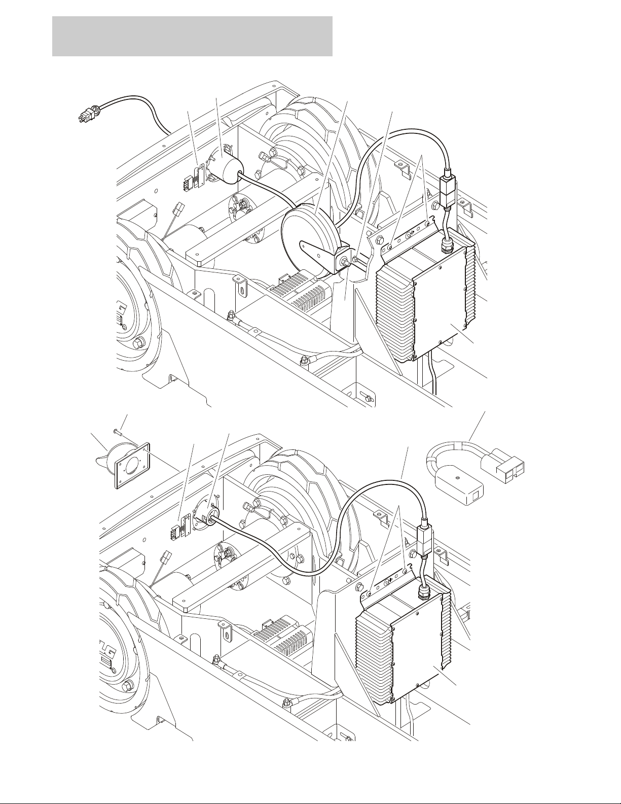
FIGURE 2-2. BATTERY CHARGER AND PLUG INSTALLATION (PRIOR TO SN 0130010886)
2-6 10MSP 3121229

SECTION 2 CONTROLS
FIGURE 2-2. BATTERY CHARGER AND PLUG INSTALLATION (PRIOR TO SN 0130010886)
ITEM # PART NUMBER QTY. DESCRIPTION REV.
Ref BATTERY CHARGER INSTALLATIONS
0274897 Ref ANSI - Charger with Plug C
0274898 Ref Australian - Charger without Plug B
0274899 Ref ANSI - Charger without Plug C
0274900 Ref ANSI - Charger with Plug/Cord Reel C
1 0100011 AR Locking Compound
2 0400241 1 Battery Charger Assembly (No Serviceable Parts Available)
3 0610131 1 LED Board
4 1060689 1 Cord, Electrical
5 3911016 4 Screw #10-24NC x 1in
3311001 2 Nut #10-24NC (Charger with Australian Plug Only)
6 4191706 4 Screw 6mm x 12mm
7 AR Cover, Terminal Options:
4460802 1 Charger with Plug
4460802 1 Charger without Plug
Not Required 0 Charger with Plug/Cord Reel
8 AR Terminal, Inlet Options:
8A 4460803 1 Charger with ANSI Plug
4460940 1 Charger with Australian Plug
Not Required 0 Charger without Plug
8B 4120046 1 Socket, Cord Reel Stop (Charger with ANSI Plug/Cord Reel
Only)
9 to 19 Not Used
Ref Note: Items 20-23 used with Charger with Plug/Cord Reel
only.
20 3680057 1 Reel, Charger Cord
20A 0791508 1 Screw 5/16in-18NC x 1in
21 4751500 1 Flatwasher 5/16in Wide
22 0791406 1 Screw 1/4in-20NC x 3/4in
23 3575423 1 Angle, Mounting
101 Use 2915230 1 BATTERY CHARGER REPROGRAM CONTROLLER KIT
(WAS P/N 1600466)
3121229 10MSP 2-7
SECTION 2 CONTROLS
2
2
3
8
9611
12
3
104
4
6
9A
10
208
207
106
105
205
202
204
206
203
102
103
1
1
101
201
301
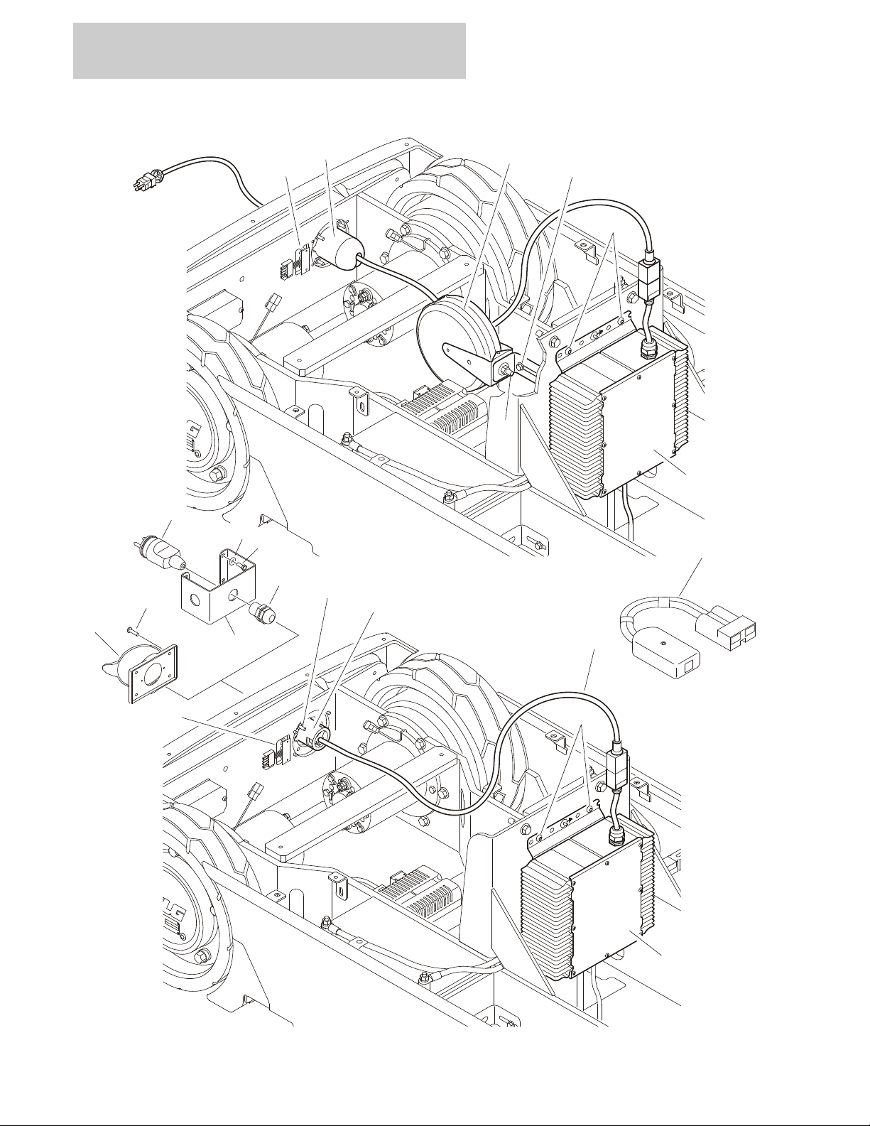
FIGURE 2-3. BATTERY CHARGER AND PLUG INSTALLATION (SN 0130010886 TO PRESENT)
2-8 10MSP 3121229

SECTION 2 CONTROLS
FIGURE 2-3. BATTERY CHARGER AND PLUG INSTALLATION (SN 0130010886 TO
PRESENT)
ITEM # PART NUMBER QTY. DESCRIPTION REV.
Ref BATTERY CHARGER INSTALLATIONS
0274898 Ref ANSI/ANSI Export - Charger without Plug F
0274900 Ref ANSI - Charger with Plug/Cord Reel F
1 0100011 AR Locking Compound
2 1 Battery Charger Assembly Options (No Serviceable Parts
Available):
Use 1001110117 SN 0130010886 to SN 0130013545 (was p/n 0400241)
1001102932 SN 0130013545 to SN 0130016980
1001136381 SN 0130016980 to Present
3 0610131 1 LED Board
4 1060689 1 Cord, Electrical
5Not Used
6 4191706 4 Screw 6mm x 12mm
7Not Used
8 4120046 1 Terminal, Inlet Socket, Cord Reel Stop (Charger with ANSI Plug/
Cord Reel Only)
Ref Note: Items 9-12 used with Charger with Plug/Cord Reel
only.
9 3680057 1 Reel, Charger Cord
9A 0791508 1 Screw 5/16in-18NC x 1in
10 4751500 1 Flatwasher 5/16in Wide
11 0791406 1 Screw 1/4in-20NC x 3/4in
12 3575423 1 Angle, Mounting
Ref CHARGER PLUG INSTALLATIONS (ANSI/ANSI EXPORT/
AUSTRALIAN SPECS)
1001097449 Ref Charger Plug 110V (ANSI/ANSI Export/CSA/Japanese Spec) B
1001097455 Ref Charger Plug 220V (Australian Spec) C
1001097456 Ref Charger Plug No Plug (ANSI Export Spec) A
101 0100011 AR Locking Compound
102 3911016 AR Screw #10-24NC x 1in
103 4460802 1Cover, Terminal
104 1 Terminal, Inlet Options:
4460803 1001097449 Installation
4460940 1001097455 Installation
Not Required 1001097456 Installation
105 3311001 2 Nut #10-24NC (1001097455 Installation Only)
106 4761000 2 Lockwasher #10 (1001097455 Installation Only)
3121229 10MSP 2-9

SECTION 2 CONTROLS
FIGURE 2-3. BATTERY CHARGER AND PLUG INSTALLATION (SN 0130010886 TO PRESENT)
(CONTINUED)
ITEM # PART NUMBER QTY. DESCRIPTION REV.
Ref CHARGER PLUG INSTALLATIONS (CE SPECS ONLY)
1001097450 Ref Charger Plug 220V Post Ground B
1001097451 Ref Charger Plug 220V Side Ground B
1001097452 Ref Charger Plug 220V Keyed Ground B
1001097453 Ref Charger Plug 110V IEC 60309 Yellow B
1001097454 Ref Charger Plug 110V IEC 60309 Blue B
1001097456 Ref Charger Plug No Plug A
201 0100011 AR Locking Compound
202 0721004 4 Screw #10-24NC x 1/2in
203 3571584 1 Plate, Plug Inlet
204 4460428 1 Connector, Strain Relief
205 1 Terminal, Male Options:
4461202 1001097450 Installation
4461205 1001097451 Installation
4461249 1001097452 Installation
4461196 1001097453 Installation
4461199 1001097454 Installation
Not Required 1001097456 Installation
206 4711000 4 Flatwasher #10
207 3911016 AR Screw #10-24NC x 1in (1001097456 Installation Only)
208 4460802 1 Cover, Terminal (1001097456 Installation Only)
301 Use 2915230 1 BATTERY CHARGER REPROGRAM CONTROLLER KIT
(WAS P/N 1600466)
2-10 10MSP 3121229

SECTION 2 CONTROLS
FIGURE 2-3. BATTERY CHARGER AND PLUG INSTALLATION (SN 0130010886 TO PRESENT)
(CONTINUED)
ITEM # PART NUMBER QTY. DESCRIPTION REV.
3121229 10MSP 2-11

SECTION 2 CONTROLS
MAST
REMOVED FOR CLARITY
5
3
17
8
7
192021
16
13
18
15
22
4
15
22
4
13
202
203
204
205
207
208
209
201
31
6
11
12
33
32
1
2
2
2 - 12VOLT BATTERIES SYSTEM
FIGURE 2-4. BATTERIES, SWITCHES, HORN AND BEACON LIGHT INSTALLATION
2-12 10MSP 3121229

MAST
REMOVED FOR CLARITY
104
103
117
107
106
119
120
122
115
113
202
203
204
205
207
208
209
201
121
101
132
133
134
101
130
130
113
4 - 6VOLT BATTERIES SYSTEM
118
116
110
105
111
112
135
SECTION 2 CONTROLS
3121229 10MSP 2-13

SECTION 2 CONTROLS
FIGURE 2-4. BATTERIES, SWITCHES, HORN AND BEACON LIGHT INSTALLATION
ITEM # PART NUMBER QTY. DESCRIPTION REV.
Ref Note: To modify machine from (2) 12V batteries to
(4) 6V batteries, use kit p/n 1001127560.
0274896 Ref BATTERIES AND ALARM INSTALLATION (2 - 12VOLT BATTER-
IES SYSTEM)
1 0100011 AR Locking Compound
2 0100051 AR Grease, Battery Terminal
3 0140022 1 Horn
4 AR Battery Options:
0400209 2 12Volt (Prior to SN 0130016980)
1001136380 2 12Volt (SN 0130016980 to Present)
5 0641404 1 Bolt 1/4in-20NC x 1/2in
6 0741005 2 Capscrew, Flat Head #10-24NC x 1/2in
7 0791003 2 Screw #10-24NC x 3/8in
8 0791406 2 Screw 1/4in-20NC x 3/4in
9 to 10 Not Used
11 2400044 1 Block, Fuse Mounting
12 2400069 1 Fuse 175Amp
13 2920178 2 Light, Strobe C
7027733 2 Bulb, Replacement (1 Per Assembly)
14 Not Used
15 3311501 4 Nut 5/16in-18NC
16 3380541 1 Shield, Wire
17 3575423 2 Plate, Battery Hold-down
18 3820032 2 Rivet
19 3911016 4 Screw #10-24NC x 1in
20 4071084 2 Shim
21 4360514 2 Switch, Proximity
22 4761500 4 Lockwasher 5/16in
23 to 30 Not Used
31 4191406 2 Screw 4mm x 12mm
32 2080040 4 Huck Fastener (SN 0130010454 to Present)
33 3380771 1 Shield, Strobe Light (SN 0130010454 to Present)
E
1001120444 Ref BATTERIES AND ALARM INSTALLATION (4 - 6VOLT BATTER-
IES SYSTEM)
101 0100011 AR Locking Compound
102 0100051 AR Grease, Battery Terminal
103 0140022 1 Horn
104 0641404 1 Bolt 1/4in-20NC x 1/2in
105 0741005 2 Capscrew, Flat Head #10-24NC x 1/2in
106 0791003 2 Screw #10-24NC x 3/8in
107 0791406 2 Screw 1/4in-20NC x 3/4in (Prior to SN 0130016983)
108 to 109 Not Used
110 2080040 4 Huck Fastener (SN 0130010454 to Present)
111 2400044 1 Block, Fuse Mounting
112 2400069 1 Fuse 175Amp
D
2-14 10MSP 3121229

SECTION 2 CONTROLS
FIGURE 2-4. BATTERIES, SWITCHES, HORN AND BEACON LIGHT INSTALLATION
(CONTINUED)
ITEM # PART NUMBER QTY. DESCRIPTION REV.
113 2920178 2 Light, Strobe C
7027733 2 Bulb, Replacement (1 Per Assembly)
114 Not Used
115 3380541 1 Shield, Wire
116 3380771 1 Shield, Strobe Light (SN 0130010454 to Present)
117 3575423 4 Plate, Battery Hold-down (Prior to SN 0130016983)
118 3820032 2 Rivet
119 3911016 4 Screw #10-24NC x 1in
120 4071084 2 Shim
121 4191406 2 Screw 4mm x 12mm
122 4360514 2 Switch, Proximity
123 to 129 Not Used
130 1001120445 4 Battery
131 Not Used
132 0641408 2 Bolt 1/4in-20NC x 1in (SN 0130015906 to SN 0130016983)
133 3311405 2 Locknut 1/4in-20NC (SN 0130015906 to SN 0130016983)
134 4711400 4 Flatwasher 1/4in Narrow (SN 0130015906 to SN 0130016983)
135 Use 1001133303 2 Plate, Battery Support (was p/n 1001129506)
0275901 Ref 7FT LIMITER SWITCH INSTALLATION (OPTIONAL) A
201 0903671 1 Bracket
202 2080040 2 Fastener, Huck
203 3572511 1 Plate
204 3820024 2 Rivet
205 3900205 2 Screw #10-24NC x 5/8in
206 4240033 AR Tie-Strap (Not Shown)
207 4360515 1 Switch, Proximity
208 4750800 2 Flatwasher #8 Wide
209 4761000 2 Lockwasher #10
3121229 10MSP 2-15

SECTION 2 CONTROLS
6
7
6
7
5C5B5A
4
6
7
6
7
5
2
3
1
1
1
1
1
FIGURE 2-5. GROUND COMPONENTS INSTALLATIONS
2-16 10MSP 3121229

SECTION 2 CONTROLS
FIGURE 2-5. GROUND COMPONENTS INSTALLATIONS
ITEM # PART NUMBER QTY. DESCRIPTION REV.
Ref GROUND CONTROLS INSTALLATION
0274894 Ref All Specs except Australian/Japanese & Chinese Specs C
0274894 Ref Australian Spec (Prior to SN 0130017845) C
1001137013 Ref Australian Spec (SN 0130017845 to Present) A
0274895 Ref Japanese & Chinese Specs Only C
1 0100011 AR Locking Compound
2 0140033 1 Alarm
3 0641404 2 Bolt 1/4in-20NC x 1/2in
4 1 Module, Traction Options:
Use 1001102847 1 Prior to SN 0130014947 (was p/n 1600397/p/n 1600451)
1001102847 1 SN 0130014947 to Present
5 1 Module, Ground Control Station Options:
1600435 All Specs except Australian/Japanese & Chinese Specs
1600435 Australian Spec (Prior to SN 0130017845)
1001136954 Australian Spec (SN 0130017845 to Present)
1600436 Japanese & Chinese Specs Only
5A 7024428 1 Emergency Stop Switch Assy
5B 1 Selector Switch Assy Options:
7024430 All Specs (Australian Spec - Prior to SN 0130017845)
7024591 Australian Spec (SN 0130017845 to Present)
5C 1 Cover Assy Options:
7024460 1 All Specs (Australian Spec - Prior to SN 0130017845)
7024592 1 Australian Spec (SN 0130017845 to Present)
6 3911020 4 Screw #10-24NC x 1-1/4in
7 4751000 4 Flatwasher #10
3121229 10MSP 2-17

SECTION 2 CONTROLS
20
103
102
28
9
18
17
8
16
6
14
10
16
2
25
16
23
22
19
3
3
19
3
5
3
3
5
6
12
16
8
15
24
201
26
27
1
1
3
1
1
101
FIGURE 2-6. PLATFORM CABLES AND CONTROLS INSTALLATION
2-18 10MSP 3121229

SECTION 2 CONTROLS
FIGURE 2-6. PLATFORM CABLES AND CONTROLS INSTALLATION
ITEM # PART NUMBER QTY. DESCRIPTION REV.
Ref PLATFORM CABLES AND CONTROLS INSTALLATIONS
0273551 Ref All Specs Except Australian Spec N
0273551 Ref Australian Spec (Prior to SN 0130017845) N
1001137012 Ref Australian Spec (SN 0130017845 to Present) A
1 0100011 AR Locking Compound
2 0641412 1 Bolt 1/4in-20NC x 1-1/2in
3 0791003 11 Screw #10-24NC x 3/8in
4Not Used
5 1320043 3 Clamp, Cable
6 1320149 2 Clamp, Hose
7Not Used
8 3311405 2 Locknut 1/4in-20NC
9 3580344 1 Pulley, Control Cable
10 3900264 1 Screw, Shoulder
11 Not Used
12 0741412 1 Screw, Countersunk 1/4in-20NC x 1-1/2in
13 Not Used
14 4160130 1 Spring, Extension
15 4340838 1 Support, Cable Mount
16 4711400 5 Flatwasher 1/4in Narrow
17 4751000 4 Flatwasher #10 Wide
18 4751500 1 Flatwasher 5/16in Wide
19 4923035 1 Harness, Base to Platform (See Section 7 for Breakdown)
20 1 Platform Control Box Assembly Options (See Control Box
Assembly for Breakdown):
All Specs to Present & Australian Spec Prior to
SN 0130017845
Use 1001098194 Prior to SN 0130010761 (was p/n 0861768)
1001098194 SN 0130010761 to Present
1001137011 Australian Spec (SN 0130017845 to Present)
21 Not Used
22 4923316 1 Harness, Platform Controls (See Section 7 for Breakdown)
23 4240018 3 Tie-Strap
24 0741003 2 Screw, Countersunk #10-24NC x 3/8in
25 0641406 2 Bolt 1/4in-20NC x 3/4in
26 3311605 Locknut 3/8in-16NC
27 1321283 1 Clamp
28 3900373 1 Screw, Shoulder
0273566 Ref PROGRAMMABLE SECURITY LOCK INSTALLATION
(OPTIONAL)
101 0100011 AR Locking Compound
102 0721003 2 Screw #10-24NC x 3/8in
103 2940161 1 Lock, Electronic
201 4923174 Ref EXTENSION CORD 110VOLT - 6FT (OPTIONAL) A
A
3121229 10MSP 2-19

SECTION 2 CONTROLS
2
2
2
10
8
5
2
16
15
6
101B
101C
101A
13A
11
13
7
14
4
12
3
9
101OR6
201
201B
201A
201C
22
21
1
1
3
1
3
1
23
OR
FIGURE 2-7. CONTROL BOX ASSEMBLY
2-20 10MSP 3121229

SECTION 2 CONTROLS
FIGURE 2-7. CONTROL BOX ASSEMBLY
ITEM # PART NUMBER QTY. DESCRIPTION REV.
Ref CONTROL BOX ASSEMBLIES
All Specs to Present & Australian Spec Prior to
SN 0130017845
Use 1001098194 Ref Prior to SN 0130010761 (was p/n 0861768) (Original
Equipment)
1001098194 Ref SN 0130010761 to Present (Service Replacement) A
Ref Note: Original Equipment Control Box p/n 0861768 may
have been replaced with Service Replacement Control Box
p/n 1001098194. Identify component before ordering parts.
1001137011 Australian Spec (SN 0130017845 to Present) A
1 0100011 AR Locking Compound
2 0630464 8 Screw, Button #10-24NC x 1/2in
3 0791404 4 Screw, Countersunk 1/4in-20NC x 1/2in
4 1 Box, Control Options:
0861767 Prior to SN 0130010761
1001098193 SN 0130010761 to Present
5 1600378 1 Module, Platform Controller
70003805 1 Decal - Directional Overlay
6 1 Controller Assembly Options:
1600454 Prior to SN 0130010761 (was p/n 1600379) (See Items
101-101C for Breakdown)
1001098192 SN 0130010761 to Present (See Items 201-201C for
Breakdown)
7 1706007 1 Decal - Emergency Stop
8 3310601 4 Nut #6-32NC
9 3380540 1 Panel, Control Box
10 3910608 4 Screw, Machine #6-32NC x 1/2in
11 AR Screw, Machine #8-32NC x 1/4in Options:
3910804 2 All Specs Except Australian Spec
3910804 2 Australian Spec (Prior to SN 0130017845)
Not Required 0 Australian Spec (SN 0130017845 to Present)
12 4340884 1 Mount, Control Box
13 AR Keyswitch Assembly Options:
4360467 1 All Specs Except Australian Spec
4360467 1 Australian Spec (Prior to SN 0130017845)
Not Required 0 Australian Spec Only (SN 0130017845 to Present)
13A 2860030 1 Pr Key, Replacement
14 4360562 1 Switch, Emergency Stop
15 4360567 1 Switch, Push Button (Includes Harness)
16 4360581 1 Switch, Rocker
17 to 20 Not Used
21 3311005 4 Locknut #10-24NC (SN 0130010761 to Present)
22 3900189 4 Screw #10-24NC x 1in (SN 0130010761 to Present)
23 AR Plug, Liquid Tight
Not Required 0 All Specs Except Australian Spec
1001137484 1 Australian Spec Only (SN 0130017845 to Present)
C
3121229 10MSP 2-21

SECTION 2 CONTROLS
FIGURE 2-7. CONTROL BOX ASSEMBLY (CONTINUED)
ITEM # PART NUMBER QTY. DESCRIPTION REV.
1600454 Ref CONTROLLER ASSEMBLY (PRIOR TO SN 0130010761) B
101 1600454 1 Controller Assembly (was p/n1600379)
101A 70000682 1 Boot, Rubber (Base of Controller)
7027766 1 Ring, Retaining
101B 7027764 1 Boot, Rubber (Steer Switch)
7027365 1 Actuator, Handle
70000684 2 Screw
70000686 2 Screw
70000683 4 Washer, Neoprene
70000685 2 Spacer
101C 7027367 1 Switch, Push Button
7027765 1 Lever, Enable
1001098192 Ref CONTROLLER ASSEMBLY (SN 0130010761 TO PRESENT) A
201 1001098192 1 Controller Assembly
201A 70001250 1 Boot, Rubber (Base of Controller)
7027766 1 Ring, Retaining
70001251 1 Bezel, Mounting
70001252 1 Gasket, Mounting
201B 70000084 1 Boot, Rubber (Steer Switch)
70000082 2 Microswitch
7027365 1 Actuator, Handle
70000684 2 Screw
70000686 2 Screw
70000683 4 Washer, Neoprene
70000685 2 Spacer
70001253 1 Gasket, Handle
201C 7027765 1 Lever, Enable
7027367 1 Switch, Push Button (Note: Not Shown - Located Behind
Lever)
2-22 10MSP 3121229

SECTION 3
MAST
3121229 10MSP 3-1

SECTION 3 MAST
38
3
22
27
45
45
34
34
52
3
38
7
7
7
26
6
9
10
50
32
51
37
13
6
11
7
26
20
7
26
19
36
16
204
26
7
206
203
210
25
29
208
211
202
205
207
35
209
50
32
51
37
14
6
36
7
26
18
26
39
40
41
24
49
49
44
7
12
38
3
48
33
22
27
52
33
48 3
38
8
8
31
31
424243
43
21
4
15
104
109
10310625106102105
1101072
846108473051772
6262449494412
730
130
230
430
530
6
1
1
1
1
1
1
1
1
1
1
1
1
1
1
1
1
1
1
101
201
FIGURE 3-1. MAST ASSEMBLY AND INSTALLATION
3-2 10MSP 3121229

SECTION 3 MAST
FIGURE 3-1. MAST ASSEMBLY AND INSTALLATION
ITEM # PART NUMBER QTY. DESCRIPTION REV.
0801394 Ref MAST ASSEMBLY D
1 0100011 AR Locking Compound
2Not Used
3 0362735 4 Bar, Sheave Pin Support
4 0561341 1 Block, Chain Anchor
5 0721006 1 Screw, Machine #10-24NC x 3/4in
6 0791003 6 Screw #10-24NC x 3/8in
7 0811408 31 Screw 1/4in-20NC x 1in
8 0791812 4 Screw 1/2in-13NC x 1-1/2in
9 0902047 1 Bracket, Sequence Cable
10 0902423 1 Bracket, Bottom Chain Attach
11 0902424 1 Bracket, Bottom Chain Attach
12 0902431 2 Bracket, Sequence Cable
13 0902445 1 Bracket, Sequence Cable
14 0902698 1 Bracket, Sequence Cable
15 1260375 1 Chain Assy - #446 (See Items 101-110 for Breakdown)
16 1260376 1 Chain Assy - #444 (See Items 201-211 for Breakdown)
17 1271567 1 Channel, Mast #1
18 1271568 1 Channel, Mast #2
19 1271569 1 Channel, Mast #3
20 1271577 1 Channel, Header
21 1 Lift Cylinder Assembly Option (See Section 5 for Breakdown):
Use 1684531 1 Prior to SN 0130011099 (was p/n 1684348)
1684531 1 SN 0130011099 to Present
22 2880310 2 Key
23 3020041 AR Lubricant (Not Shown - Used on Slides)
24 3311408 2 Nut, Flanged 1/4in-20NC
25 3311601 8 Nut 3/8in-16 NC
26 3340845 12 Pad, Slide Guide
27 3422717 2 Pin, Sheave
28 3422750 1 Pin, Chain Equalizer
29 3422752 1 Pin, Chain Equalizer
30 3422757 1 Pin, Keeper
31 3570893 2 Plate, Cylinder Mounting
32 3580269 2 Sheave, Sequence Cable
33 3580286 2 Sheave Assembly
0440246 2 Bearing (1 Per Assembly)
34 3580293 2 Sheave Assembly
0440249 2 Bearing (1 Per Assembly)
35 3760383 1 Ring, Retaining
36 3890039 2 Cable, Sequence
37 3900187 2 Screw, Shoulder
38 3900192 8 Screw, Countersunk 3/8in-16NC x 1/2in
39 4070860 AR Shim, Slide Pad
40 4070861 AR Shim, Slide Pad
41 4070862 AR Shim, Slide Pad
42 4070970 AR Shim, Cylinder Mount
43 4070971 AR Shim, Cylinder Mount
3121229 10MSP 3-3

SECTION 3 MAST
FIGURE 3-1. MAST ASSEMBLY AND INSTALLATION (CONTINUED)
ITEM # PART NUMBER QTY. DESCRIPTION REV.
44 4160124 2 Spring
45 4567491 2 Tube, Spacer
46 4567750 1 Tube, Spacer
47 4567751 1 Tube, Spacer
48 4740007 2 Washer, Thrust
49 4740414 4 Washer, Cup
50 4751000 8 Flatwasher #10 Wide
51 4751500 2 Flatwasher 5/16in Wide
52 4569003 3 Tube, Spacer
— — — — — — — — — —
0273417 1 Mast Kit (Includes Items 17-20) G
1260375 Ref CHAIN ASSEMBLY - #446 CHAIN B
101 0100062 AR Loctite #RC/640
102 0561153 2 Block, Chain Anchor
103 0561409 2 Block, Chain Anchor
104 Purchased Assy AR Chain
105 3422338 2 Pin, Equalizer
106 3422346 4 Pin, Grooved
107 3450304 2 Pin, Cotter
108 3571101 1 Plate, Chain Adjustment
109 4300111 2 Stud
110 4751500 2 Flatwasher 5/16in
1260376 Ref CHAIN ASSEMBLY - #444 CHAIN C
201 Use 0100019 AR Loctite #RC/640 (was p/n 0100062)
202 0561149 2 Block, Chain Anchor
203 0561408 2 Block, Chain Anchor
204 Purchased Assy AR Chain
205 3422338 2 Pin, Equalizer
206 3422346 2 Pin, Grooved
207 3452355 2 Pin, Grooved
208 3450304 2 Pin, Cotter
209 3571103 1 Plate, Chain Adjustment
210 4300111 2 Stud
211 4751500 2 Flatwasher 5/16in
0273545 Ref MAST INSTALLATION B
301 0100019 AR Locking Compound
302 0641609 3 Bolt 3/8in-16NC x 1-1/8in
303 Not Used
304 3311601 4 Nut 3/8in-16NC
305 4711600 8 Flatwasher 3/8in Narrow
306 0641612 1 Bolt 3/8in-16NC x 1-1/2in
3-4 10MSP 3121229

SECTION 4
PLATFORM
3121229 10MSP 4-1

SECTION 4 PLATFORM
105
103
105
103
102
11
28
27
104
7
10
6
13
13
29
29
25
26
21
4
101
3
16
12
8
5
17
29
14
21
20
18
1
1
FIGURE 4-1. PLATFORM INSTALLATION (ALL SPECS TO PRESENT & AUSTRALIAN SPEC
PRIOR TO SN 0130018678)
4-2 10MSP 3121229

SECTION 4 PLATFORM
FIGURE 4-1. PLATFORM INSTALLATION (ALL SPECS TO PRESENT & AUSTRALIAN SPEC
PRIOR TO SN 0130018678)
ITEM # PART NUMBER QTY. DESCRIPTION REV.
3510865 Ref PLATFORM ASSEMBLY H
1 0100011 AR Locking Compound
2Not Used
3 2 Screw Options:
0751006 Prior to SN 0130012278
0751003 SN 0130012278 to Present
4 1671168 1 Floor, Platform
5 2080040 16 Fastener, Huck
6 2410012 1 Rail, Door (Right Side)
7 2410013 1 Rail, Door (Left Side)
8 2600294 4 Hinge
9Not Used
10 3340962 2 Pad
11 3510860 1 Rail, Platform
12 3510862 1 Pan, Molded Platform
13 3520072 8 Cap-Plug
14 4071095 AR Shim
15 Not Used
16 4360572 1 Footswitch
17 0641416 8 Bolt 1/4in-20NC x 2in
18 0751003 4 Screw
19 Not Used
20 4360573 2 Switch, Proximity
21 2080043 13 Rivnut
22 Not Used
23 8882320 AR Sealant, Seam (Not Shown)
24 Not Used
25 3900258 5 Screw, Button Head 1/4in-20NC x 3/4in
26 4711400 5 Flatwasher 1/4in Narrow
27 1120582 1 Plug
28 1120583 1 Grip, Foam
29 AR Stop/Hinge, Gate Options:
Use 4220309 2 Bottom Stop/Hinge Prior to SN 0130009782 (was p/n 4220233)
Use 4220309 2 Top Stop/Hinge Prior to SN 0130009782 (was p/n 4220234)
4220309 4 Top & Bottom Stop/Hinge SN 0130009782 to Present
0274055 Ref PLATFORM INSTALLATION C
Ref Note: Replacement decals must be ordered separately - See
Section 8.
101 0641622 2 Bolt 3/8in-16NC x 2-3/4in
102 0741614 4 Screw, Flat Head 3/8in-16NC x 1-3/4in
103 3311605 6 Locknut 3/8in-16NC
104 3510865 1 Platform Assembly (Includes Items 1-29)
105 4711600 8 Flatwasher 3/8in Narrow
3121229 10MSP 4-3

SECTION 4 PLATFORM
104
103
104
103
102
11
28
27
7
10
6
13
13
22
29
25
26
21
4
101
16
18
12
8
5
17
29
14
21
20
18
1
1
1
32
31
15
2
19
26
30
3
9
26
1
FIGURE 4-2. PLATFORM INSTALLATION (AUSTRALIAN SPEC ONLY) (SN 0130018678 TO
PRESENT)
4-4 10MSP 3121229

SECTION 4 PLATFORM
FIGURE 4-2. PLATFORM INSTALLATION (AUSTRALIAN SPEC ONLY) (SN 0130018678 TO
PRESENT)
ITEM # PART NUMBER QTY. DESCRIPTION REV.
1001148752 Ref PLATFORM ASSEMBLY A
1 0100011 AR Locking Compound
2 280013 6in/15cm Conduit
3 0641415 2 Bolt 1/4in-20NC x 1-7/8in
4 1671168 1 Floor, Platform
5 2080040 16 Fastener, Huck
6 1001148753 1 Rail, Door (Right Side)
7 1001148754 1 Rail, Door (Left Side)
8 2600294 4 Hinge
9 3300151 2 Nut, Acorn 1/4in-20NC
10 3340962 2 Pad
11 3510860 1 Rail, Platform
12 3510862 1 Pan, Molded Platform
13 3520072 8 Cap-Plug
14 4071095 AR Shim
15 3300381 2 Nut, Coupling
16 4360572 1 Footswitch
17 0641416 8 Bolt 1/4in-20NC x 2in
18 0751003 6 Screw
19 3931456 2 Bolt 1/4in-20NC x 3-1/2in
20 4360573 2 Switch, Proximity
21 2080043 13 Rivnut
22 1001100141 2 Stop, Swing Gate
23 8882320 AR Sealant, Seam (Not Shown)
24 Not Used
25 3900258 5 Screw, Button Head 1/4in-20NC x 3/4in
26 4711400 9 Flatwasher 1/4in Narrow
27 1120582 1 Plug
28 1120583 1 Grip, Foam
29 4220309 2 Stop, Swing Gate
30 1001100142 2 Handle
31 1001100634 2 Spring
32 1001101529 2 Pin, Plunger
1001149003 Ref PLATFORM INSTALLATION A
Ref Note: Replacement decals must be ordered separately - See
Section 8.
101 0641622 2 Bolt 3/8in-16NC x 2-3/4in
102 0741614 4 Screw, Flat Head 3/8in-16NC x 1-3/4in
103 3311605 6 Locknut 3/8in-16NC
104 4711600 8 Flatwasher 3/8in Narrow
105 1001148752 1 Platform Assembly (Includes Items 1-29)
3121229 10MSP 4-5

SECTION 4 PLATFORM
54 161612317
10
6
8
2
14110
10
13
16
15
17719
FIGURE 4-3. MATERIAL TRAY INSTALLATION
4-6 10MSP 3121229

SECTION 4 PLATFORM
FIGURE 4-3. MATERIAL TRAY INSTALLATION
ITEM # PART NUMBER QTY. DESCRIPTION REV.
0274011 Ref MATERIAL TRAY INSTALLATION F
1 0100011 AR Locking Compound
2 0440287 6 Bearing
3 0811610 2 Screw 3/8in-16NC x 1-1/4in
4 1580027 1 Tray
5 2080040 8 Fastener, Huck
6 2360684 1 Frame
7 3321701 6 Nut 7/16in-20NF
8 3340962 4 Pad
9Not Used
10 3450302 4 Pin, Cotter
11 Not Used
12 4220222 2 Stop
13 4711600 2 Flatwasher 3/8in Narrow
14 4711700 18 Flatwasher 7/16in Narrow
15 2940165 1 Latch, Material Tray
16 1001097488 2 Pin, Plunger (was p/n 3423171)
17 4740476 2 Thrust Washer
18 Not Used
19 0100019 AR Locking Compound
3121229 10MSP 4-7

SECTION 4 PLATFORM
3
7
11
10
4
5
1
12
12
8
2
9
13
13
6
FIGURE 4-4. OPTIONAL BICYCLE CARRIERS INSTALLATION
4-8 10MSP 3121229

SECTION 4 PLATFORM
FIGURE 4-4. OPTIONAL BICYCLE CARRIERS INSTALLATION
ITEM # PART NUMBER QTY. DESCRIPTION REV.
Ref BICYCLE CARRIER INSTALLATION
0273570 Ref Carrier on One Side Only B
0273571 Ref Carrier on Both Sides B
Ref Note: Qty Shown is for One Side Only. Double for Both Sides.
1 0641424 2 Bolt 1/4in-20NC x 3in
2 0641618 1 Bolt 3/8in-16NC x 2-1/4in
3 0902895 1 Bracket, Hanger
4 1060799 1 Lanyard
5 1320316 1 Clamp, Block
6 1706134 1 Decal - Maximum Capacity
7 2660121 1 Arm
8 3311405 2 Locknut 1/4in-20NC
9 3311605 1 Locknut 3/8in-16NC
10 3420198 1 Pin, Quick Release
11 4240163 1 Strap
12 4711400 4 Flatwasher 1/4in Narrow
13 4711600 2 Flatwasher 3/8in
3121229 10MSP 4-9

SECTION 4 PLATFORM
206
202
5
3
5
3
203
204
201
205
203
104
105
102
4
4
6
103
101
102
1
2
FIGURE 4-5. OPTIONAL RUG CARRIER INSTALLATION
4-10 10MSP 3121229

SECTION 4 PLATFORM
FIGURE 4-5. OPTIONAL RUG CARRIER INSTALLATION
ITEM # PART NUMBER QTY. DESCRIPTION REV.
0240107 Ref RUG CARRIER INSTALLATION B
1 0240108 1 Accessory, Rug Carrier (Rear) (See Items 101 - 105 for
Breakdown)
2 0240109 1 Accessory, Rug Carrier (Front) (See Items 201 - 206 for
Breakdown)
3 0791406 4 Bolt 1/4in-20NC x 3/4in
4 2080040 4 Fastener, Huck
5 3311408 4 Nut 1/4in-20NC
6 1706134 1 Decal - Capacity
0240108 Ref ACCESSORY RUG CARRIER (REAR) A
101 3311405 1 Locknut 1/4in-20NC
102 3520176 2 Plug
103 3931408 1 Screw 1/4in-20NC x 1/2in
104 4568208 1 Tube
105 4630009 1 Carrier Pivot
0240109 Ref ACCESSORY RUG CARRIER (FRONT) A
201 3311405 1 Locknut 1/4in-20NC
202 3422744 1 Pin, Plunger
203 3520176 2 Plug
204 3931408 1 Screw 1/4in-20NC x 1/2in
205 4569158 1 Tube
206 4630010 1 Carrier Pivot
3121229 10MSP 4-11

SECTION 4 PLATFORM
185674329
FIGURE 4-6. OPTIONAL FLUORESCENT TUBE CADDY ASSEMBLY
4-12 10MSP 3121229

SECTION 4 PLATFORM
FIGURE 4-6. OPTIONAL FLUORESCENT TUBE CADDY ASSEMBLY
ITEM # PART NUMBER QTY. DESCRIPTION REV.
0255040 Ref FLUORESCENT TUBE CADDY ASSEMBLY B
1 4844840 1 Weldment, Fluorescent Tube Caddy
2 4280296 2ft/0.7m Strip, Wear
3 3421453 1 Pin, Snapper
4 3760170 1 Ring, Split
5 1060380 1 Cable, Lanyard
6 0641410 1 Bolt 1/4in-20NC x 1-1/4in
7 3311405 1 Locknut 1/4in-20NC
8 1702365 1 Decal - JLG
9 1706326 1 Decal - Max Capacity (15lb./7kg)
3121229 10MSP 4-13

SECTION 4 PLATFORM
FIGURE 4-6. OPTIONAL FLUORESCENT TUBE CADDY ASSEMBLY (CONTINUED)
ITEM # PART NUMBER QTY. DESCRIPTION REV.
4-14 10MSP 3121229

SECTION 5
CYLINDER
3121229 10MSP 5-1

SECTION 5 CYLINDER
1514181619
13
3
6
111012
9
1
7
5
8
4
2
100
FIGURE 5-1. LIFT CYLINDER ASSEMBLY (ORIGINAL EQUIPMENT) (PRIOR TO
SN 0130011099)
5-2 10MSP 3121229

SECTION 5 CYLINDER
FIGURE 5-1. LIFT CYLINDER ASSEMBLY (ORIGINAL EQUIPMENT) (PRIOR TO SN
0130011099)
ITEM # PART NUMBER QTY. DESCRIPTION REV.
Ref Note: Original Equipment Cylinder may have been replaced
with Service Replacement Cylinder. Identify p/n stamped on
cylinder before ordering parts.
1684348 Ref LIFT CYLINDER ASSEMBLY (ORIGINAL EQUIPMENT) H
1 7027847 1 Head
2 7027848 1 Rod
3 7027849 1 Piston
4 7027850 1 Barrel
5 Use 7027855 1 O-Ring
6 Use 7027855 1 O-Ring
7 Use 7027855 1 Seal, Rod
8 Use 7027855 1 Ring, Back-up
9 Use 7027855 1 Wiper, Rod
10 Use 7027855 1 Ring, Wear
11 Use 7027855 1 Seal, Piston
12 7027340 1 Nut
13 2220886 1 Plug
7027851 1 Valve, Flow Control
14 7027852 1 Valve, Check
15 7027853 1 Valve, Manual Descent
See Note 1 Coil (Note: Not Available - Use p/n 7027853)
16 2221172 1 Fitting
17 2221173 1 Fitting
18 2220591 1 Fitting, Reducer
19 2220883 3 Plug
Ref KIT OPTIONS:
100 7027855 1 Seal Kit (includes items 5-11)
3121229 10MSP 5-3

SECTION 5 CYLINDER
12
13
141720
18
4
10
8
9
11
5
3
6
7
1
2
19
20
100
FIGURE 5-2. LIFT CYLINDER ASSEMBLY (SERVICE REPLACEMENT) (SN 0130011099 TO
PRESENT)
5-4 10MSP 3121229

SECTION 5 CYLINDER
FIGURE 5-2. LIFT CYLINDER ASSEMBLY (SERVICE REPLACEMENT) (SN 0130011099 TO
PRESENT)
ITEM # PART NUMBER QTY. DESCRIPTION REV.
1684531 Ref LIFT CYLINDER ASSEMBLY (SERVICE REPLACEMENT) C
1 70000991 1 Barrel
2 70000992 1 Rod
3 70000993 1 Head
4 7023392 1 Piston
5 Use 7023395 1 Wiper, Rod
6 Use 7023395 1 Seal, Rod
7 Use 7023395 1 O-Ring
8 Use 7023395 1 Seal, Piston
9 Use 7023395 1 Ring, Wear
10 Use 7023395 1 O-Ring
11 7023391 1 Nut
12 70000994 1 Valve, Manual Descent
70001113 1 Coil
7026625 1 Cartridge
7026624 1 Manual Override
7026623 1 Seal Kit
13 70000218 1 Valve, Check
14 2220591 1 Fitting, Reducer
15 2221173 1 Fitting
16 Not Used
17 2221172 1 Fitting
18 70000995 1 Valve, Flow Control
19 See Note 1 Plug (Note: Not Available - Purchase Locally)
20 See Note 4 Plug (Note: Not Available - Purchase Locally)
Ref KIT OPTIONS:
100 7023395 1 Seal Kit (includes items 5-10)
3121229 10MSP 5-5

SECTION 5 CYLINDER
FIGURE 5-2. LIFT CYLINDER ASSEMBLY (SERVICE REPLACEMENT) (SN 0130011099 TO
PRESENT) (CONTINUED)
ITEM # PART NUMBER QTY. DESCRIPTION REV.
5-6 10MSP 3121229

SECTION 6
HYDRAULIC
3121229 10MSP 6-1

SECTION 6 HYDRAULIC
3
4
6
5
101
102
103
LIFT CYLINDER REF.
PUMP REF.
FIGURE 6-1. HYDRAULIC DIAGRAM
6-2 10MSP 3121229

SECTION 6 HYDRAULIC
FIGURE 6-1. HYDRAULIC DIAGRAM
ITEM # PART NUMBER QTY. DESCRIPTION REV.
Ref HYDRAULIC SYSTEM INSTALLATION
0273546 Ref Standard Hydraulic Oil E
0274181 Ref Fire Resistant Hydraulic Oil A
1 to 2 Not Used
3 2120183 1 Filter, In-Line
4 2221123 1 Fitting, Straight
5 2221185 1 Fitting, Elbow
6 2754025 2 Hose
Ref CYLINDER FITTINGS OPTIONS:
Use 1684531 Ref Prior to SN 0130011099 (Was p/n 1684348)H
1684531 Ref SN 0130011099 to Present A
101 2221173 1 Fitting, Straight Push Coupling
102 2221172 1 Fitting, Straight Push Coupling
103 2220591 1 Fitting, Reducer
Ref TOOLS
7027247 1 Tool, Perma-Push Insert Disconnect (Not Shown)
3121229 10MSP 6-3

SECTION 6 HYDRAULIC
FIGURE 6-1. HYDRAULIC DIAGRAM (CONTINUED)
ITEM # PART NUMBER QTY. DESCRIPTION REV.
6-4 10MSP 3121229

SECTION 7
ELECTRICAL
3121229 10MSP 7-1

SECTION 7 ELECTRICAL
119M
P3
P4
P5
GROUND CONTROL
BOX
CHARGER
LED
LIGHTS
119H
119F
119G
228B
214
228
224A
224
224
226
225
212
228A
230B
229H
229E
506A
506
507A
507
229F
229G
229C
229A
229
229K
229D
229
119L
229A
119K
PLAT
AUX
#1
PLAT
AUX
#2
AUX
OUTPUT
#1
AUX
OUTPUT
#2
BRUSH
INDICATOR
RELAY
AUX
INPUT
#2
FOOT
SWITCH
119J
PUMP/
MOTOR
TRACTION
MODULE
M1
M2
12VOLT
BATTERIES
P1
P2
LIFT
CYLINDER
HORN
ALARM
229B
213A
213
BEACON #2
(MAST MTD)
BEACON #1
(BASE MTD)
229A
213A
213
501
501A
501A
501
PLATFORM
CONSOLE
BOX
6A
6B615
15A
20
19
19A
20B
122B
122
20A
17
17A
18A
18
502
SECURITY
LOCK
122A
119
119B
119C
119D
119E
119
119A
MAST
JUNCTION
BOX
502A
309
119
119
105
225
209
210
AC
INPUT
401
308A
304
304A
309A
302E
302K
302F
302G
302H
303A
310B
310A
303
302D
302C
504A
505A
505
505A
504
ELEVATION/SPEED
CUTBACK SWITCHES
221
221A
221A
229D
229D
HEIGHT
LIMITER
SWITCH
PLATFORM
GATE
SWITCH
PLATFORM
GATE
SWITCH
TILT
PHP
229J
226
227
227
227A
230B
230
230A
230A
223
OR
CORD
REEL
308B
311
311A
503
BATTERY
CHARGER
302L
302L
302A
302B
LEFT
DRIVE
MOTOR
RIGHT
DRIVE
MOTOR
105
402
307
107
214
228
310
OR
310
310
310C
ELECTRICAL SYSTEM 24VDC (2-12VOLT BATTERIES)
21
21A
FIGURE 7-1.ELECTRICAL COMPONENTS INSTALLATION
7-2 10MSP 3121229

SECTION 7 ELECTRICAL
119M
P3
P4
P5
GROUND CONTROL
BOX
CHARGER
LED
LIGHTS
119H
119F
119G
228B
214
228
225
228A
230B
229H
229E
506A
506
507A
507
229F
229G
229C
229A
229
229K
229D
229
119L
229A
119K
PLAT
AUX
#1
PLAT
AUX
#2
AUX
OUTPUT
#1
AUX
OUTPUT
#2
BRUSH
INDICATOR
RELAY
AUX
INPUT
#2
FOOT
SWITCH
119J
PUMP/
MOTOR
TRACTION
MODULE
M1
M2
6VOLT
BATTERIES
P1
P2
LIFT
CYLINDER
HORN
ALARM
229B
213A
213
BEACON #2
(MAST MTD)
BEACON #1
(BASE MTD)
229A
213A
213
PLATFORM
CONSOLE
BOX
6A
6B
6
15
15A
20
19
19A
20B
122B
122
20A
17
17A
18A
18
502
SECURITY
LOCK
122A
119
119B
119C
119D
119E
119
119A
MAST
JUNCTION
BOX
502A
309
119
119
105
225
209
210
AC
INPUT
401
308A
304
304A
309A
302E
302K
302F
302G
302H
303A
310B
310A
303
302D
302C
504A
505A
505
505A
504
ELEVATION/SPEED
CUTBACK SWITCHES
221
221A
221A
229D
229D
HEIGHT
LIMITER
SWITCH
PLATFORM
GATE
SWITCH
PLATFORM
GATE
SWITCH
TILT
PHP
229J
226
227
227
227A
230B
230
OR
CORD
REEL
308B
311
311A
503
BATTERY
CHARGER
302L
302L
302A
302B
105
402
307
107
214
228
230A
501
501A
501A
501
230A
LEFT
DRIVE
MOTOR
RIGHT
DRIVE
MOTOR
212
224
224A
226
231
231
310
ELECTRICAL SYSTEM 24VDC (4-6VOLT BATTERIES)
310
310
310C
21
21A
3121229 10MSP 7-3

SECTION 7 ELECTRICAL
FIGURE 7-1. ELECTRICAL COMPONENTS INSTALLATION
ITEM PART NUMBER QTY DESCRIPTION REV
Ref PLATFORM CONTROL BOX COMPONENTS
Ref All Specs to Present & Australian Spec Prior to
SN 0130017845
Use 1001098194 Ref Prior to SN 0130010761 (was p/n 0861768 C
1001098194 Ref SN 0130010761 to Present A
1001137011 Ref Australian Spec (SN 0130017845 to Present) A
1 to 5 Not Used
6 See Note 1 Controller Harness (Note: Not Available for Purchase) B
6A 250201 1 Connector - 10 Position
4461023 9 Socket, Female
6B 7027366 1 Microswitch Harness
7 to 14 Not Used
15 4360567 1 Horn Harness (Includes Horn) B
15A 250206 1 Connector - 2 Position
4461023 2 Socket, Female
16 Not Used
17 4923106 1 Drive/Lift Select Harness B
17A 250200 1 Connector - 6 Position
4461023 3 Socket, Female
18 4923107 1 Emergency Stop Harness A
18A 250206 1 Connector - 2 Position
4461023 2 Socket, Female
19 4923108 1 Keyswitch Harness (All Specs to Present & Australian Spec Prior
to SN 0130017845)
19A 250206 1 Connector - 2 Position
4461023 2 Socket, Female
20 4923315 1 Power Harness A
20A 4461041 1 Connector - 8 Position
4461023 6 Socket, Female
20B 70001798 1 Connector, Female - 9 Position
70001799 6 Pin, Male
21 1001137026 1 Keyswitch Bypass Harness (Australian Spec Only -
SN 0130017845 to Present)
21A See Note 1 Connector - 2 Position (Note: Not Available for Purchase)
4461023 2 Socket, Female
A
A
Ref CABLES AND CONTROLS INSTALLATIONS
0273551 Ref All Specs Except Australian Spec N
0273551 Ref Australian Spec (Prior to SN 0130017845) N
1001137012 Ref Australian Spec (SN 0130017845 to Present) A
101 to 104 Not Used
105 1320043 3 Clamp, Cable
106 Not Used
107 3020038 AR Grease, Contact
108 to 118 Not Used
119 4923035 1 Mast Harness G
1060927
15.5ft/4.7m
Cable, Electrical - 18/12
7-4 10MSP 3121229

SECTION 7 ELECTRICAL
FIGURE 7-1. ELECTRICAL COMPONENTS INSTALLATION (CONTINUED)
ITEM PART NUMBER QTY DESCRIPTION REV
119A 7023498 1 Connector, Female - 9 Position
70001705 6 Pin, Male
119B 70000344 1 Connector, Female - 4 Position
4461025 4 Pin, Male
119C 4460424 1 Connector, Female - 2 Position
4460226 2 Socket, Female
119D 4460424 1 Connector, Female - 2 Position
4460267 2 Pin, Male
119E 4460663 1 Connector, Strain Relief
119F 1180392 1 Carrier, Power Track
7027734 AR Link, Repair
119G 7027736 1 Foot, Mounting (End #1 - Closest to Junction Box)
119H 7027735 1 Foot, Mounting (End #2 - Furthest From Junction Box)
119J 250201 1 Connector - 10 Position
4461023 7 Socket, Female
119K 4460320 1 Connector - 2 Position
4460226 2 Socket, Female
119L 4460320 1 Connector - 2 Position
4460267 2 Pin, Male
119M 250199 1 Connector - 4 Position
4461023 2 Socket, Female
120 to 121 Not Used
122 4923316 1 Platform Harness A
122A 70001703 1 Connector - 9 Position
70001704 1 Backshell
70001705 6 Socket, Female
122B 70001706 1 Connector - 9 Position
70001707 1 Backshell
70001708 6 Socket, Female
Ref ELECTRICAL SYSTEM INSTALLATIONS
0274896 Ref 2 - 12Volt Batteries System E
1001120444 Ref 4 - 6Volt Batteries System D
201 to 208 Not Used
209 1060943 1 Cable, Electrical (Ground Control + to Pump +)
210 1060944 1 Cable, Electrical (Ground Control – to Pump –)
211 Not Used
212 2400069 1 Fuse 175 Amp
213 2920178 2 Strobe Light Harness (Includes Strobe Light)
213A 4460320 2 Connector - 2 Position
4460226 4 Socket, Female
214 3020038 AR Grease, Contact
215 to 220 Not Used
221 4360514 2 Proximity Harness (Includes Switch) A
221A 4460424 1 Connector - 2 Position
4460227 2 Pin, Male
222 Not Used
3121229 10MSP 7-5

SECTION 7 ELECTRICAL
FIGURE 7-1. ELECTRICAL COMPONENTS INSTALLATION (CONTINUED)
ITEM PART NUMBER QTY DESCRIPTION REV
223 4923021 1 Cable, Battery (B+ to B–) (2 - 12Volt Batteries System Only) B
See Note 1 Boot, Red (Note: Not Available for Purchase)
See Note 1 Boot, Red (Note: Not Available for Purchase)
224 4923022 1 Cable, Battery (B+ to Fuse) B
See Note 2 Boot, Red (Note: Not Available for Purchase)
224A 4460216 2 Connector, Anderson (Blue)
225 4923023 1 Cable, Battery (Fuse to Ground Control +) A
See Note 2 Boot, Red (Note: Not Available for Purchase)
226 4923024 1 Cable, Battery (B– to Ground Control –) A
See Note 2 Boot, Black (Note: Not Available for Purchase)
227 4923028 1 Traction Module Power Harness C
227A Use 4923028 1 Connector - 2 Position (Note: Not Available for Purchase)
228 4923029 1 Ground Control to Traction Module Harness A
228A Use 4923029 1 Connector - 6 Position (Note: Not Available for Purchase)
228B Use 4923029 1 Connector - 6 Position (Note: Not Available for Purchase)
229 4923446 1 Main Harness D
229A 4460424 3 Connector - 2 Position
4460227 6 Pin, Male
229B 4460424 1 Connector - 2 Position
4460267 2 Pin, Male
229C 4460424 1 Connector - 2 Position
4460227 1 Pin, Male
4460226 1 Socket, Female
229D 4460320 3 Connector - 2 Position
4460226 6 Socket, Female
229E 4460320 2 Connector - 2 Position
4460227 4 Pin, Male
229F 4460320 1 Connector - 2 Position
4460227 1 Pin, Male
4460226 1 Socket, Female
229G 4460445 1 Connector - 3 Position
4460227 3 Pin, Male
229H 4460919 1 Connector - 20 Position
4460672 19 Socket, Female
229J 4460920 1 Connector - 14 Position
4460672 14 Socket, Female
229K 3740069 1 Relay
3990010 2 Diode 6A/600V
230 4933346 1 Drive Motor/Brake Electrical Diagram D
4923383 1 Drive Motor/Brake Harness E
230A 4460897 2 Connector - 2 Position
4460464 4 Pin, Male
230B 4461108 2 Connector - 4 Position
231 1001121700 3 Cable, Battery (B+ to B –) (4 - 6Volt Batteries System Only) A
See Note 2 Boot, Black (Note: Not Available for Purchase)
7-6 10MSP 3121229

SECTION 7 ELECTRICAL
FIGURE 7-1. ELECTRICAL COMPONENTS INSTALLATION (CONTINUED)
ITEM PART NUMBER QTY DESCRIPTION REV
Ref BATTERY CHARGER INSTALLATIONS
0274897 Ref Charger with ANSI Plug (Prior to SN 0130010886) C
0274900 Ref Charger with ANSI Plug/Cord Reel D
0274899 Ref Charger without Plug (Prior to SN 0130010886) C
0274898 Ref Charger without Plug D
301 Not Used
302 Ref Battery Charger Components
302A See Note 1 AC Cord (Note: Not Available for Purchase)
302B See Note 1 Receptacle, Female (Note: Not Available for Purchase)
302C See Note 1 DC Harness (Note: Not Available for Purchase)
302D 4460648 1 Connector, Anderson
302E See Note 1 Enable Harness (Note: Not Available for Purchase)
302F 4460424 1 Connector, Male - 2 Position
4460267 2 Pin, Male
302G 7022920 1 LED Board Connector Harness
302H 4460899 1 Connector - 6 Position
4460464 4 Pin, Male
4460466 2 Seal
302K See Note 1 Connector, Strain Relief (Note: Not Available for Purchase)
302L See Note 1 Connector, Strain Relief (Note: Not Available for Purchase)
303 0610131 1 Charger LED Harness (Includes PC Board) E
303A 4460321 1 Connector - 4 Position
4460226 4 Socket, Female
304 1060689 1 AC Extension Cord A
304A Use 1060689 1 Plug, Male
305 to306 Not Used
307 AR Cover, Terminal Options (Prior to SN 0130010886):
4460802 1 Charger with Plug (Prior to SN 0130010886)
4460802 1 Charger without Plug (Prior to SN 0130010886)
Not Required 0 Charger with Plug/Cord Reel (Prior to SN 0130010886)
308 AR Terminal, Inlet Options:
308A 4460803 1 Charger with ANSI Plug (Prior to SN 0130010886)
4460940 1 Charger with Australian Plug (Prior to SN 0130010886)
Not Required 0 Charger without Plug (Prior to SN 0130010886)
308B 4120046 1 Socket, Cord Reel Stop (Charger with ANSI Plug/Cord Reel
Only)
309 4923438 1 Battery Charger Harness A
309A 4460648 1 Connector, Anderson
310 1 Charger LED Extension Harness Options:
4923378 Prior to SN 0130013545 B
1001109821 SN 0130013545 to Present A
310A 4460894 1 Connector - 6 Position
4460465 4 Socket, Female
310B 4460761 1 Connector - 4 Position
4460226 4 Socket, Female
310C 1001102771 1 Sensor (SN 0130013545 to Present)
311 3680057 1 Cord Reel (Charger with ANSI Plug/Cord Reel Only)
311A Use 3680057 1 Plug, Male (Note: Not Available for Purchase)
3121229 10MSP 7-7

SECTION 7 ELECTRICAL
FIGURE 7-1. ELECTRICAL COMPONENTS INSTALLATION (CONTINUED)
ITEM PART NUMBER QTY DESCRIPTION REV
Ref AC CHARGER PLUG INSTALLATIONS
1001097449 Ref Charger Plug 110V (ANSI/ANSI Export/CSA/Japanese Spec) B
1001097450 Ref Charger Plug 220V Post Ground (CE Spec) B
1001097451 Ref Charger Plug 220V Side Ground (CE Spec) B
1001097452 Ref Charger Plug 220V Keyed Ground (CE Spec) B
1001097453 Ref Charger Plug 110V IEC 60309 Yellow (CE Spec) B
1001097454 Ref Charger Plug 110V IEC 60309 Blue (CE Spec) B
1001097455 Ref Charger Plug 220V (Australian Spec) B
1001097456 Ref Charger Plug No Plug (ANSI Export /CE Spec) B
401 AR Cover, Terminal Options:
4460802 1 1001097449 / 1001097455 / 1001097456 Installations
Not Required 0 1001097450 / 1001097451 / 1001097452 / 1001097453 /
1001097454 Installations
402 AR Terminal, Inlet Options:
4460803 1 1001097449 Installation
4461202 1 1001097450 Installation
4461205 1 1001097451 Installation
4461249 1 1001097452 Installation
4461196 1 1001097453 Installation
4461199 1 1001097454 Installation
4460940 1 1001097455 Installation
Not Required 0 1001097456 Installation
MISCELLANEOUS HARNESS COMPONENTS
501 See Note 2 Motor/Brake Harness (Note: Not Available for Purchase)
501A 4460891 2 Connector - 2 Position
4460465 4 Socket, Female
502 Use 2940161 1 Security Lock Harness (Optional) (Note: Not Available for
Purchase)
502A 250199 1 Connector - 4 Position
4461023 4 Socket, Female
503 4923174 1 Extension Cord (Optional)
504 Use 4360572 1 Footswitch Harness (Includes Switch)
504A 4460424 1 Connector - 2 Position
4460226 2 Socket, Female
505 Use 4360573 1 Platform Gate Switch & Footswitch Harness
505A 4460320 2 Connector - 2 Position
4460267 4 Pin, Male
506 See Note 1 Manual Descent (Lift Cylinder) Harness (Note: Not Available -
Purchase Replacement Coil - See Section 5)
506A 4460424 1 Connector - 2 Position
4460226 2 Socket, Female
507 Use 4360515 1 Height Limiter Harness (Includes Switch)
507A 4460424 1 Connector - 2 Position
4460226 2 Socket, Female
7-8 10MSP 3121229

SECTION 7 ELECTRICAL
FIGURE 7-1. ELECTRICAL COMPONENTS INSTALLATION (CONTINUED)
ITEM PART NUMBER QTY DESCRIPTION REV
TOOLS (NOT SHOWN)
601 7002821 Ref Crimper (For Wire to Pin/Socket Connections)
602 7002828 1 Stripper, Wire
603 to 605 Not Used
606 7002842 1 Brake Crimp Removal Tool (Not Shown)
607 7002841 1 Motor Crimp Removal Tool (Not Shown)
608 7016618 1 Molex Tool (For Ground Control Station Electrical Connectors)
609 7002841 1 Intech Tool (For Drive Motor Electrical Connectors)
610 7002842 1 Intech Tool (For Drive Motor Brake Electrical Connectors)
611 7002847 1 Tyco/AMP Electronics Tool (For other General Electrical
Connectors)
612 7002848 1 Tyco/AMP Electronics Tool (For other General Electrical
Connectors)
3121229 10MSP 7-9

SECTION 7 ELECTRICAL
FIGURE 7-1. ELECTRICAL COMPONENTS INSTALLATION (CONTINUED)
ITEM PART NUMBER QTY DESCRIPTION REV
7-10 10MSP 3121229

SECTION 8
DECALS
3121229 10MSP 8-1

SECTION 8 DECALS
11
12
4
111
108
110
201
10
6
4
13
14
6
2
105
107
201
106
5
109
101
8
9
102
104
1
6
6
11
10
3
103
112
113
4
7
108
108
103
112
113
PRIOR TO
S/N 0130015319
S/N 0130015319
TO PRESENT
FIGURE 8-1. DECAL INSTALLATION
8-2 10MSP 3121229

SECTION 8 DECALS
FIGURE 8-1. DECAL INSTALLATION
ITEM # PART NUMBER QTY. DESCRIPTION REV.
0274935 Ref COMMON DECALS INSTALLATION E
1 1700584 1 Decal - Patent (Prior to SN 0130016814)
2 1701640 1 Decal - Manual
3 See Note 1 Decal - Barcode (Note: Not Available for Purchase)
4 3 Decal - JLG Options:
1703177 Prior to SN 0130019804
1703681 SN 0130019804 to Present
5 1705624 1 Decal - Lanyard Attach
6 4 Decal - Wheel Load Options:
1705930 Prior to SN 0130017845
1001143557 SN 0130017845 to Present
7 1705992 1 Decal - Manual Descent
8 1705994 1 Decal - Taillight Reflector (Right) (Prior to SN 0130008828 Only)
9 1705996 1 Decal - Taillight Reflector (Left) (Prior to SN 0130008828 Only)
10 1706131 1 Decal - Danger
11 1706743 2 Decal - Sumo Supermotor 10MSP
12 1706764 1 Decal - jlg.com Website
13 3820032 4 Rivet
14 8990147 1 Holder, Manual
70003486 2 Clip, Manual Holder
Ref COUNTRY SPEC DECALS INSTALLATION
0275130 Ref ANSI Spec (English Language) D
0275135 Ref ANSI Export Spec (Chinese Language) C
0275130 Ref ANSI Export Spec (English Language) D
0275134 Ref ANSI Export Spec (Portuguese Language) C
0275133 Ref ANSI Export Spec (Spanish Language) C
0275136 Ref Australian Spec C
0275132 Ref CE Spec (All Languages) B
0275130 Ref CSA Spec (English Language) D
0275131 Ref CSA Spec (French Language) D
0275137 Ref Japanese Spec B
101 1703779 1 Decal - USA (ANSI, ANSI Export & CSA English Language
Spec Only)
102 1 Decal - Crushing Hazard Options:
1703786 ANSI Spec (English Language)
1706090 ANSI Spec (Chinese Language)
1703786 ANSI Export Spec (English Language)
1706086 ANSI Spec (Portuguese Language)
1706082 ANSI Spec (Spanish Language)
1705099 Australian Spec
1705099 CE Spec (All Languages)
1703786 CSA Spec (English Language)
1706094 CSA Spec (French Language)
1705099 Japanese Spec
3121229 10MSP 8-3

SECTION 8 DECALS
FIGURE 8-1. DECAL INSTALLATION (CONTINUED)
ITEM # PART NUMBER QTY. DESCRIPTION REV.
103 1 Decal - CSA Options:
1705303 CSA Spec Only
Not Required All Specs Except CE Spec
104 1 Decal - Battery Charging Instructions Options:
1705929 ANSI Spec (English Language)
1706093 ANSI Spec (Chinese Language)
1705929 ANSI Export Spec (English Language)
1706089 ANSI Spec (Portuguese Language)
1706085 ANSI Spec (Spanish Language)
1706077 Australian Spec
1706077 CE Spec (All Languages)
1705929 CSA Spec (English Language)
1706097 CSA Spec (French Language)
1706077 Japanese Spec
105 1 Decal - Warning Options:
1705937 ANSI Spec (English Language)
1706092 ANSI Spec (Chinese Language)
1705937 ANSI Export Spec (English Language)
1706088 ANSI Spec (Portuguese Language)
1706084 ANSI Spec (Spanish Language)
Not Required Australian Spec
Not Required CE Spec (All Languages)
1705937 CSA Spec (English Language)
1706096 CSA Spec (French Language)
Not Required Japanese Spec
106 1 Decal - Danger Options:
1705938 ANSI Spec (English Language)
1706091 ANSI Spec (Chinese Language)
1705938 ANSI Export Spec (English Language)
1706087 ANSI Spec (Portuguese Language)
1706083 ANSI Spec (Spanish Language)
1706078 Australian Spec
1706078 CE Spec (All Languages)
1705938 CSA Spec (English Language)
1706095 CSA Spec (French Language)
1706078 Japanese Spec
107 1 Decal - Capacity Options:
1705939 ANSI, ANSI Export & CSA Specs
1706079 Australian, CE & Japanese CE Specs
108 3 Decal - Crushing Hazard Options:
1705995 ANSI Spec (English Language)
1706090 ANSI Spec (Chinese Language)
1705995 ANSI Export Spec (English Language)
1706086 ANSI Spec (Portuguese Language)
1706082 ANSI Spec (Spanish Language)
1705099 Australian Spec
1705099 CE Spec (All Languages)
1705995 CSA Spec (English Language)
1706094 CSA Spec (French Language)
1705099 Japanese Spec
8-4 10MSP 3121229

SECTION 8 DECALS
FIGURE 8-1. DECAL INSTALLATION (CONTINUED)
ITEM # PART NUMBER QTY. DESCRIPTION REV.
109 1 Decal - Fall Restraint Options:
1706115 ANSI Spec (English Language)
1706117 ANSI Spec (Chinese Language)
1706115 ANSI Export Spec (English Language)
1706118 ANSI Spec (Portuguese Language)
1706116 ANSI Spec (Spanish Language)
Not Required Australian Spec
Not Required CE Spec (All Languages)
1706115 CSA Spec (English Language)
1706119 CSA Spec (French Language)
Not Required Japanese Spec
110 1706616 1 Decal - Capacity
111 1706617 1 Decal - No Riders
112 2080057 4 Fastener
113 See Note 1 Nameplate - Serial Number (Note: Not Available for
Purchase)
114 1 Decal - Patent Options (SN 0130016814 to Present):
1001131273 ANSI, ANSI Export (English Language) & CSA Spec Only
Not Required All Specs Except ANSI, ANSI Export (English Language) &
CSA Spec
Ref SERVICE DECAL INSTALLATION (OPTIONAL)
0274568 Ref Decal - Alternative Service (Target Specs) C
Use 0274568 Ref Decal - Alternative Service (Sears Specs) (was p/n 0275923) C
201 1 Decal - Alternative Service
Use1001110242 Decal - Service Support: 1-877-523-3374 (was p/n 1705304
& 1001091144) (Target Specs)
Use1001110242 Decal - Service Support: 1-877-554-2112 (Sears Specs) (was
p/n 1001091150)
Ref Note: Illustration shows (2) #201 call-outs because location
may vary.
3121229 10MSP 8-5

SECTION 8 DECALS
FIGURE 8-1. DECAL INSTALLATION (CONTINUED)
ITEM # PART NUMBER QTY. DESCRIPTION REV.
8-6 10MSP 3121229

SECTION 9 RECOMMENDED SERVICE
PARTS STOCK
10MSP
The following list will service one machine (built to current production per date on the front cover) with emergency repair
parts which can be installed in the field. Parts from the list should be replaced when inventory is depleted to keep service
parts stock supplied. For further information, contact your JLG dealer or the JLG Industries Parts Department.
Part Number Description Qty./Machine
STANDARD PARTS Ref
7011069 Breather (Figure 2-1) 1
2400069 Fuse 175 Amp (Figure 2-4 & 7-2) 2
4360514 Proximity Switch (Figure 2-4 & 7-2) 1
7024428 Emergency Stop Switch (Figure 2-5) 1
7024430 Selector Switch (Figure 2-5) 1
1001098192 Controller Assembly (Figure 2-7) 1
4360467 Keyswitch (Figure 2-7) 1
2860030 Key, Replacement (Figure 2-7) 1
4360562 Switch, Emergency (Figure 2-7) 1
4360567 Switch, Push Button (Figure 2-7) 1
4360581 Switch, Rocker (Figure 2-7) 1
4360572 Footswitch (Figure 4-1) 1
4360573 Proximity Switch (Figure 4-1) 1
2120183 Filter, In-Line (Figure 6-1) 4
7027734 Carrier Power Track Repair Link (Figure 7-2) 1
3740069 Relay (Figure 7-2) 1
3990010 Diode (Figure 7-2) 2
VARIABLE PARTS Ref
4360515 Switch, Proximity (Machines with Height Limit) (Figure 2-4) 1
1600451 Traction Module (Figure 2-5) 1
1600435 Ground Control Module (All Specs except Australian/Japanese & Chinese
Specs) (Figure 2-5)
1001136954 Ground Control Module (Australian Spec) (Figure 2-5) 1
1600436 Ground Control Module (Japanese & Chinese Specs) (Figure 2-5) 1
1600378 Platform Control Module (Figure 2-7) 1
1
3121229 10MSP 9-1

SECTION 9 RECOMMENDED SERVICE
PARTS STOCK
10MSP
The following list will service one machine (built to current production per date on the front cover) with emergency repair
parts which can be installed in the field. Parts from the list should be replaced when inventory is depleted to keep service
parts stock supplied. For further information, contact your JLG dealer or the JLG Industries Parts Department.
Part Number Description Qty./Machine
9-2 10MSP 3121229

SECTION 10 SPECIAL OPTIONS
Note: This list is to accommodate machines ordered with special equipment. Options may not
be applicable to all models. For more specific parts information contact JLG Parts Department.
FIG & ITEM # PART NUMBER QTY. DESCRIPTION REV.
10—1 Ref MISCELLANEOUS SPECIAL OPTIONS
1001127560 Ref Battery Convertion Kit (Converts (2)12Volt battery system to
(4)6Volt battery system)
1001091680 Ref Strap, Cargo
Ref Decals Installations
0274053 Ref Target Spec
Ref Electrical Connector Kits
1001148902 Ref Amp Connector Kit
1001148903 Ref Deutsch DT Connector Kit
1001148904 Ref Deutsch HD Connector Kit
1001148905 Ref Packard Connector Kit
1001148906 Ref Various Connector Kit
1001112957 Ref Gate Alarm Installation
0240112 Ref Scanner Pocket
1580031 1 Pocket, Scanner
4341005 1 Mount, Pocket
Tools for Service:
7002821 1 Crimper (For Wire to Pin/Socket Connections)
7002823 1 Extractor (For Removal of Pin/Sockets Connectors)
4460467 1 Extractor 16-18 Gauge (For Wire to Pin/Socket from Deutsch
Connectors)
4460510 1 Extractor 12-14 Gauge (For Wire to Pin/Socket from Deutsch
Connectors)
7016654 1 Screwdriver, Magnetic
7004275 1 Seal Tool - 1”
7004276 1 Seal Tool - 1 1/2”
7002826 1 Seal Tool 2”
8896941 1 Stripper, Wire
2915027 1 Rear Wheel Puller
7002842 1 Brake Crimp Removal Tool (Not Shown)
7002841 1 Motor Crimp Removal Tool (Not Shown)
7016618 1 Molex Tool (For Ground Control Station Electrical Connectors)
7002841 1 Intech Tool (For Drive Motor Electrical Connectors)
7002842 1 Intech Tool (For Drive Motor Brake Electrical Connectors)
7002847 1 Tyco / AMP Electronics Tool (For other General Electrical
Connectors)
7002848 1 Tyco / AMP Electronics Tool (For other General Electrical
Connectors)
7027247 1 Perma-Push insert Disconnect Tool (For Hydraulic Fittings)
Use 31201384 Ref Video, Operators (was p/n 3125081)
3121229 10MSP 10-1

SECTION 10 SPECIAL OPTIONS
Note: This list is to accommodate machines ordered with special equipment. Options may not
be applicable to all models. For more specific parts information contact JLG Parts Department.
FIG & ITEM # PART NUMBER QTY. DESCRIPTION REV.
10-2 10MSP 3121229

SECTION 11 PART NUMBER INDEX
PagePart Number PagePart Number PagePart Number
0100011 1-3, 1-4, 1-11, 2-4,
2-7, 2-9, 2-10, 214, 2-17, 2-19,
2-21, 3-3, 4-3, 4-
5, 4-7
0100019 ..................3-4, 4-7
0100051 ....................... 2-14
0100062 ......................... 3-4
0100081 ......................... 1-3
0140022 ....................... 2-14
0140033 ....................... 2-17
0240103 ......................... 1-4
0240107 ....................... 4-11
0240108 ....................... 4-11
0240109 ....................... 4-11
0240112 ....................... 10-1
0240114 ....................... 1-11
0255040 ....................... 4-13
0273417 ......................... 3-4
0273545 ......................... 3-4
0273546 ..................2-4, 6-3
0273551 ................2-19, 7-4
0273566 ....................... 2-19
0273570 ......................... 4-9
0273571 ......................... 4-9
0274011 ......................... 4-7
0274053 ....................... 10-1
0274055 ......................... 4-3
0274078 ......................... 1-4
0274181 ..................2-4, 6-3
0274568 ......................... 8-5
0274893 ......................... 1-3
0274894 ....................... 2-17
0274895 ....................... 2-17
0274896 ................2-14, 7-5
0274897 ..................2-7, 7-7
0274898 ...........2-7, 2-9, 7-7
0274899 ..................2-7, 7-7
0274900 ...........2-7, 2-9, 7-7
0274901 ....................... 1-11
0274904 ......................... 1-3
0274935 ......................... 8-3
0275130 ......................... 8-3
0275131 ......................... 8-3
0275132 ......................... 8-3
0275133 ......................... 8-3
0275134 ......................... 8-3
0275135 ......................... 8-3
0275136 ......................... 8-3
0275137 ......................... 8-3
0275901 ....................... 2-15
0275923 ......................... 8-5
0362735 ......................... 3-3
0400209 ....................... 2-14
0400241 ..................2-7, 2-9
0440246 ......................... 3-3
0440249 ......................... 3-3
0440287 ......................... 4-7
0440306 ......................... 1-3
0440307 ......................... 1-3
0440308 ......................... 1-3
0561149 ......................... 3-4
0561153 ......................... 3-4
0561341 ......................... 3-3
0561408 ......................... 3-4
0561409 ......................... 3-4
0610131 ........... 2-7, 2-9, 7-7
0630464 ....................... 2-21
0630580 ......................... 1-3
0641404 .............. 2-14, 2-17
0641406 ....................... 2-19
0641408 ................ 1-4, 2-15
0641410 ....................... 4-13
0641412 ....................... 2-19
0641413 ......................... 1-3
0641415 ......................... 4-5
0641416 .................. 4-3, 4-5
0641424 ......................... 4-9
0641606 .................. 1-4, 2-4
0641609 ........... 1-3, 1-4, 3-4
0641612 ......................... 3-4
0641616 ....................... 1-11
0641617 ................ 1-4, 1-11
0641618 ......................... 4-9
0641622 .................. 4-3, 4-5
0721003 ....................... 2-19
0721004 ....................... 2-10
0721006 ......................... 3-3
0741003 ....................... 2-19
0741005 ....................... 2-14
0741412 ....................... 2-19
0741614 .................. 4-3, 4-5
0751003 .................. 4-3, 4-5
0751006 ......................... 4-3
0791003 ....... 2-14, 2-19, 3-3
0791404 ....................... 2-21
0791406 2-7, 2-9, 2-14, 4-11
0791508 .................. 2-7, 2-9
0791812 ......................... 3-3
0801394 ......................... 3-3
0811408 ......................... 3-3
0811610 ................ 1-11, 4-7
0861767 ....................... 2-21
0861768 ....... 2-19, 2-21, 7-4
0902047 ......................... 3-3
0902423 ......................... 3-3
0902424 ......................... 3-3
0902431 ......................... 3-3
0902445 ......................... 3-3
0902698 ......................... 3-3
0902895 ......................... 4-9
0903120 ......................... 1-4
0903121 ......................... 1-4
0903222 ....................... 1-11
0903671 ....................... 2-15
0940049 ....................... 1-11
0940132 ......................... 1-3
0940152 ......................... 1-4
0940153 .........................1-4
1001091144 ................... 8-5
1001091150 ................... 8-5
1001091680 ................. 10-1
1001097449 ............2-9, 7-8
1001097450 ..........2-10, 7-8
1001097451 ..........2-10, 7-8
1001097452 ..........2-10, 7-8
1001097453 ..........2-10, 7-8
1001097454 ..........2-10, 7-8
1001097455 ............2-9, 7-8
1001097456 .. 2-9, 2-10, 7-8
1001097488 ................... 4-7
1001098192 2-21, 2-22, 9-1
1001098193 ................. 2-21
1001098194 2-19, 2-21, 7-4
1001098810 ................... 1-3
1001100141 ................... 4-5
1001100142 ................... 4-5
1001100634 ................... 4-5
1001100840 ................... 1-3
1001101529 ................... 4-5
1001102771 ................... 7-7
1001102847 ................. 2-17
1001102932 ................... 2-9
1001109821 ................... 7-7
1001110117 ................... 2-9
1001110242 ................... 8-5
1001112957 ................. 10-1
1001114467 ................... 1-3
1001120444 ..........2-14, 7-5
1001120445 ................. 2-15
1001120531 ................. 1-11
1001121648 ................. 1-11
1001121700 ................... 7-6
1001127560 ........2-14, 10-1
1001129506 ................. 2-15
1001131273 ................... 8-5
1001133303 ................. 2-15
1001136380 ................. 2-14
1001136381 ................... 2-9
1001136954 ..........2-17, 9-1
1001137011 2-19, 2-21, 7-4
1001137012 ..........2-19, 7-4
1001137013 ................. 2-17
1001137026 ................... 7-4
1001137484 ................. 2-21
1001143557 ................... 8-3
1001148752 ................... 4-5
1001148753 ................... 4-5
1001148754 ................... 4-5
1001148902 ................. 10-1
1001148903 ................. 10-1
1001148904 ................. 10-1
1001148905 ................. 10-1
1001148906 ................. 10-1
1001149003 ................... 4-5
1060380 .......................4-13
1060689 .......... 2-7, 2-9, 7-7
Part Number
1060799 ......................... 4-9
1060927 ......................... 7-4
1060943 ......................... 7-5
1060944 ......................... 7-5
1120582 .................. 4-3, 4-5
1120583 .................. 4-3, 4-5
1180392 ......................... 7-5
1260375 .................. 3-3, 3-4
1260376 .................. 3-3, 3-4
1271567 ......................... 3-3
1271568 ......................... 3-3
1271569 ......................... 3-3
1271577 ......................... 3-3
1320043 ................ 2-19, 7-4
1320149 ....................... 2-19
1320316 ......................... 4-9
1321283 ....................... 2-19
1380169 ....................... 1-11
1580027 ......................... 4-7
1580031 ....................... 10-1
1600378 ................ 2-21, 9-1
1600379 .............. 2-21, 2-22
1600397 ....................... 2-17
1600435 ................ 2-17, 9-1
1600436 ................ 2-17, 9-1
1600451 ................ 2-17, 9-1
1600454 .............. 2-21, 2-22
1671141 ....................... 1-11
1671143 ....................... 1-11
1671146 ....................... 1-11
1671168 .................. 4-3, 4-5
1671298 ....................... 1-11
1684348 ...........3-3, 5-3, 6-3
1684531 ...........3-3, 5-5, 6-3
1700584 ......................... 8-3
1701640 ......................... 8-3
1702365 ....................... 4-13
1703177 ......................... 8-3
1703681 ......................... 8-3
1703779 ......................... 8-3
1703786 ......................... 8-3
1704412 ......................... 2-4
1705099 .................. 8-3, 8-4
1705303 ......................... 8-4
1705304 ......................... 8-5
1705624 ......................... 8-3
1705929 ......................... 8-4
1705930 ......................... 8-3
1705937 ......................... 8-4
1705938 ......................... 8-4
1705939 ......................... 8-4
1705992 ......................... 8-3
1705994 ......................... 8-3
1705995 ......................... 8-4
1705996 ......................... 8-3
1706007 ....................... 2-21
1706077 ......................... 8-4
1706078 ......................... 8-4
1706079 ......................... 8-4
Page
3121229 10MSP 11-1

SECTION 11 PART NUMBER INDEX
PagePart Number PagePart Number PagePart Number
1706082 ..................8-3, 8-4
1706083 ......................... 8-4
1706084 ......................... 8-4
1706085 ......................... 8-4
1706086 ..................8-3, 8-4
1706087 ......................... 8-4
1706088 ......................... 8-4
1706089 ......................... 8-4
1706090 ..................8-3, 8-4
1706091 ......................... 8-4
1706092 ......................... 8-4
1706093 ......................... 8-4
1706094 ..................8-3, 8-4
1706095 ......................... 8-4
1706096 ......................... 8-4
1706097 ......................... 8-4
1706115 ......................... 8-5
1706116 ......................... 8-5
1706117 ......................... 8-5
1706118 ......................... 8-5
1706119 ......................... 8-5
1706131 ......................... 8-3
1706134 ................4-9, 4-11
1706326 ....................... 4-13
1706616 ......................... 8-5
1706617 ......................... 8-5
1706743 ......................... 8-3
1706764 ......................... 8-3
2080040 2-14, 2-15, 4-3, 4-5,
4-7, 4-11
2080043 ..................4-3, 4-5
2080057 ......................... 8-5
2110606 ......................... 2-4
2120183 ..................6-3, 9-1
2220591 ...........5-3, 5-5, 6-3
2220883 ......................... 5-3
2220886 ......................... 5-3
2221123 ......................... 6-3
2221172 ...........5-3, 5-5, 6-3
2221173 ...........5-3, 5-5, 6-3
2221185 ..................2-4, 6-3
2300014 ......................... 2-4
2300021 ......................... 2-4
2360684 ......................... 4-7
2360750 ......................... 1-3
2400044 ....................... 2-14
2400069 .........2-14, 7-5, 9-1
2410012 ......................... 4-3
2410013 ......................... 4-3
250199 ....................7-5, 7-8
250200 ........................... 7-4
250201 ....................7-4, 7-5
250206 ........................... 7-4
2600294 ..................4-3, 4-5
2660121 ......................... 4-9
2754025 ......................... 6-3
280013 ........................... 4-5
2860030 ................2-21, 9-1
2880310 ......................... 3-3
2915027 ........................10-1
2915230 ................ 2-7, 2-10
2920178 ....... 2-14, 2-15, 7-5
2940161 ................ 2-19, 7-8
2940165 ..........................4-7
3020029 ..........................1-3
3020038 .................. 7-4, 7-5
3020039 ..........................1-3
3020041 ..........................3-3
31201384 ......................10-1
3125081 ........................10-1
3160323 .................. 1-3, 1-7
3271405 ..........................1-3
3300151 ..........................4-5
3300381 ..........................4-5
3300454 ........................1-11
3310601 ........................2-21
3311001 .................. 2-7, 2-9
3311005 ........................2-21
3311405 1-4, 2-15, 2-19, 4-9,
4-11, 4-13
3311408 ................ 3-3, 4-11
3311501 ........................2-14
3311601 .................. 3-3, 3-4
3311605 1-3, 1-4, 1-11, 2-19,
4-3, 4-5, 4-9
3321701 ..........................4-7
3340845 ..........................3-3
3340962 ........... 4-3, 4-5, 4-7
3380540 ........................2-21
3380541 .............. 2-14, 2-15
3380771 .............. 2-14, 2-15
3420198 ..........................4-9
3421453 ........................4-13
3422338 ..........................3-4
3422346 ..........................3-4
3422717 ..........................3-3
3422744 ........................4-11
3422750 ..........................3-3
3422752 ..........................3-3
3422757 ..........................3-3
3423171 ..........................4-7
3450302 ..........................4-7
3450304 ..........................3-4
3452355 ..........................3-4
3510860 .................. 4-3, 4-5
3510862 .................. 4-3, 4-5
3510865 ..........................4-3
3520072 .................. 4-3, 4-5
3520176 ........................4-11
3570893 ..........................3-3
3571101 ..........................3-4
3571103 ..........................3-4
3571584 ........................2-10
3572511 ........................2-15
3575423 2-7, 2-9, 2-14, 2-15
3580269 ..........................3-3
3580286 ..........................3-3
3580293 ..........................3-3
3580344 .......................2-19
3600392 ..................2-3, 2-4
3680057 ...........2-7, 2-9, 7-7
3740069 ..................7-6, 9-1
3760115 .........................1-3
3760170 .......................4-13
3760308 .......................1-11
3760365 .......................1-11
3760383 .........................3-3
3760496 .........................1-3
3820024 .......................2-15
3820032 .......2-14, 2-15, 8-3
3890039 .........................3-3
3900174 .......................1-11
3900187 .........................3-3
3900189 .......................2-21
3900192 .........................3-3
3900205 .......................2-15
3900258 .........1-11, 4-3, 4-5
3900264 .......................2-19
3900283 .........................1-4
3900373 .......................2-19
3910608 .......................2-21
3910804 .......................2-21
3911016 2-7, 2-9, 2-10, 2-14,
2-15
3911020 .......................2-17
3931408 .......................4-11
3931456 .........................4-5
3960590 .........................1-3
3990010 ..................7-6, 9-1
4070860 .........................3-3
4070861 .........................3-3
4070862 .........................3-3
4070970 .........................3-3
4070971 .........................3-3
4071084 ..............2-14, 2-15
4071095 ..................4-3, 4-5
4071113 .........................1-3
4071114 .........................1-3
4120046 ...........2-7, 2-9, 7-7
4160124 .........................3-4
4160130 .......................2-19
4191406 ..............2-14, 2-15
4191706 ..................2-7, 2-9
4220222 .........................4-7
4220233 .........................4-3
4220234 .........................4-3
4220309 ..................4-3, 4-5
4240018 .......................2-19
4240033 .......................2-15
4240147 .........................1-3
4240163 .........................4-9
4280296 .......................4-13
4300111 .........................3-4
4340838 .......................2-19
4340884 .......................2-21
4341005 .......................10-1
4341067 .......................1-11
Part Number
4341155 ......................... 1-3
4360467 ................ 2-21, 9-1
4360514 2-14, 2-15, 7-5, 9-1
4360515 ......... 2-15, 7-8, 9-1
4360562 ................ 2-21, 9-1
4360567 ......... 2-21, 7-4, 9-1
4360572 .... 4-3, 4-5, 7-8, 9-1
4360573 .... 4-3, 4-5, 7-8, 9-1
4360581 ................ 2-21, 9-1
4460216 ......................... 7-6
4460226 .... 7-5, 7-6, 7-7, 7-8
4460227 .................. 7-5, 7-6
4460267 .... 7-5, 7-6, 7-7, 7-8
4460320 ........... 7-5, 7-6, 7-8
4460321 ......................... 7-7
4460424 .... 7-5, 7-6, 7-7, 7-8
4460428 ....................... 2-10
4460445 ......................... 7-6
4460464 .................. 7-6, 7-7
4460465 .................. 7-7, 7-8
4460466 ......................... 7-7
4460467 ....................... 10-1
4460510 ....................... 10-1
4460648 ......................... 7-7
4460663 ......................... 7-5
4460672 ......................... 7-6
4460761 ......................... 7-7
4460802 .2-7, 2-9, 2-10, 7-7,
7-8
4460803 .... 2-7, 2-9, 7-7, 7-8
4460891 ......................... 7-8
4460894 ......................... 7-7
4460897 ......................... 7-6
4460899 ......................... 7-7
4460919 ......................... 7-6
4460920 ......................... 7-6
4460940 .... 2-7, 2-9, 7-7, 7-8
4461023 ........... 7-4, 7-5, 7-8
4461025 ......................... 7-5
4461041 ......................... 7-4
4461108 ......................... 7-6
4461196 ................ 2-10, 7-8
4461199 ................ 2-10, 7-8
4461202 ................ 2-10, 7-8
4461205 ................ 2-10, 7-8
4461249 ................ 2-10, 7-8
4520281 ......................... 1-3
4520326 ......................... 1-3
4520342 ......................... 1-3
4520343 ......................... 1-3
4520352 ......................... 1-4
4520565 ......................... 1-3
4567491 ......................... 3-4
4567750 ......................... 3-4
4567751 ......................... 3-4
4568208 ....................... 4-11
4569003 ......................... 3-4
4569158 ....................... 4-11
4630009 ....................... 4-11
Page
11-2 10MSP 3121229

SECTION 11 PART NUMBER INDEX
PagePart Number PagePart Number PagePart Number
4630010 ....................... 4-11
4711000 ....................... 2-10
4711400 1-3, 2-15, 2-19, 4-3,
4-5, 4-9
4711600 1-3, 1-11, 3-4, 4-3,
4-5, 4-7, 4-9
4711700 ......................... 4-7
4740007 ......................... 3-4
4740414 ......................... 3-4
4740476 ......................... 4-7
4750800 ....................... 2-15
4751000 .......2-17, 2-19, 3-4
4751400 ................1-4, 1-11
4751500 1-11, 2-7, 2-9, 2-19,
3-4
4761000 ................2-9, 2-15
4761500 ....................... 2-14
4844840 ....................... 4-13
4923021 ......................... 7-6
4923022 ......................... 7-6
4923023 ......................... 7-6
4923024 ......................... 7-6
4923028 ......................... 7-6
4923029 ......................... 7-6
4923035 ................2-19, 7-4
4923106 ......................... 7-4
4923107 ......................... 7-4
4923108 ......................... 7-4
4923174 ................2-19, 7-8
4923315 ......................... 7-4
4923316 ................2-19, 7-5
4923378 ......................... 7-7
4923383 ......................... 7-6
4923438 ......................... 7-7
4923446 ......................... 7-6
4933346 ......................... 7-6
70000082 ..................... 2-22
70000084 ..................... 2-22
70000191 ....................... 1-7
70000210 ................1-7, 1-8
70000211 ................1-7, 1-8
70000212 ................1-7, 1-8
70000213 ................1-7, 1-8
70000214 ................1-7, 1-8
70000215 ....................... 1-7
70000218 ....................... 5-5
70000344 ....................... 7-5
70000682 ..................... 2-22
70000683 ..................... 2-22
70000684 ..................... 2-22
70000685 ..................... 2-22
70000686 ..................... 2-22
70000935 ....................... 1-7
70000991 ....................... 5-5
70000992 ....................... 5-5
70000993 ....................... 5-5
70000994 ....................... 5-5
70000995 ....................... 5-5
70001113 ....................... 5-5
70001250 ..................... 2-22
70001251 ..................... 2-22
70001252 ..................... 2-22
70001253 ..................... 2-22
70001703 ....................... 7-5
70001704 ....................... 7-5
70001705 ....................... 7-5
70001706 ....................... 7-5
70001707 ....................... 7-5
70001708 ....................... 7-5
70001798 ....................... 7-4
70001799 ....................... 7-4
70003486 ....................... 8-3
70003805 ..................... 2-21
7002821 ................ 7-9, 10-1
7002823 ....................... 10-1
7002826 ....................... 10-1
7002828 ......................... 7-9
7002841 ................ 7-9, 10-1
7002842 ................ 7-9, 10-1
7002847 ................ 7-9, 10-1
7002848 ................ 7-9, 10-1
7004275 ....................... 10-1
7004276 ....................... 10-1
7010928 ......................... 2-3
7011004 ......................... 2-3
7011008 ......................... 2-3
7011009 ......................... 2-3
7011011 ......................... 2-3
7011013 ......................... 2-3
7011016 ......................... 2-3
7011017 ......................... 2-3
7011021 ......................... 2-3
7011024 ......................... 2-3
7011025 ......................... 2-3
7011027 ......................... 2-3
7011029 ......................... 2-3
7011031 ......................... 2-3
7011032 ......................... 2-3
7011033 ......................... 2-3
7011034 ......................... 2-3
7011069 .................. 2-3, 9-1
7016618 ................ 7-9, 10-1
7016654 ....................... 10-1
7022920 ......................... 7-7
7023391 ......................... 5-5
7023392 ......................... 5-5
7023395 ......................... 5-5
7023498 ......................... 7-5
7024428 ................ 2-17, 9-1
7024430 ................ 2-17, 9-1
7024460 ....................... 2-17
7024591 ....................... 2-17
7024592 ....................... 2-17
7024747 .................. 1-7, 1-8
7024748 ......................... 1-8
7024756 .................. 1-7, 1-8
7024758 .................. 1-7, 1-8
7026623 ......................... 5-5
7026624 .........................5-5
7026625 .........................5-5
7027247 ................6-3, 10-1
7027340 .........................5-3
7027365 .......................2-22
7027366 .........................7-4
7027367 .......................2-22
7027733 ..............2-14, 2-15
7027734 ..................7-5, 9-1
7027735 .........................7-5
7027736 .........................7-5
7027764 .......................2-22
7027765 .......................2-22
7027766 .......................2-22
7027847 .........................5-3
7027848 .........................5-3
7027849 .........................5-3
7027850 .........................5-3
7027851 .........................5-3
7027852 .........................5-3
7027853 .........................5-3
7027855 .........................5-3
7027943 .........................2-3
7027944 .........................2-3
7027945 .........................2-3
7027946 .........................2-3
7027947 .........................2-3
7027948 .........................2-4
7027949 .........................2-4
8882320 ..................4-3, 4-5
8882970 .........................1-3
8896941 .......................10-1
8990147 .........................8-3
Part Number
Page
3121229 10MSP 11-3

SECTION 11 PART NUMBER INDEX
PagePart Number PagePart Number PagePart Number
Part Number
Page
11-4 10MSP 3121229


McConnellsburg PA. 17233-9533
3121229
JLG Worldwide Locations
Corporate Office
JLG Industries, Inc.
1 JLG Drive
USA
(717) 485-5161
(717) 485-6417
JLG Industries (Australia)
P.O. Box 5119
11 Bolwarra Road
Port Macquarie
N.S.W. 2444
Australia
+61 2 65 811111
+61 2 65 813058
JLG Deutschland GmbH
Max-Planck-Str. 21
D - 27721 Ritterhude - Ihlpohl
Germany
+49 (0)421 69 350 20
+49 (0)421 69 350 45
Plataformas Elevadoras
JLG Iberica, S.L.
Trapadella, 2
P.I. Castellbisbal Sur
08755 Castellbisbal, Barcelona
Spain
+34 93 772 4700
+34 93 771 1762
JLG Latino Americana Ltda.
Rua Eng. Carlos Stevenson,
80-Suite 71
13092-310 Campinas-SP
Brazil
+55 19 3295 0407
+55 19 3295 1025
JLG Equipment Services Ltd.
Rm 1107 Landmark North
39 Lung Sum Avenue
Sheung Shui N. T.
Hong Kong
(852) 2639 5783
(852) 2639 5797
JLG Sverige AB
Enkopingsvagen 150
Box 704
SE - 176 27 Jarfalla
Sweden
+46 (0)850 659 500
+46 (0)850 659 534
www.jlg.com
JLG Industries (UK) Ltd
Bentley House
Bentley Avenue
Middleton
Greater Manchester
M24 2GP - England
+44 (0)161 654 1000
+44 (0)161 654 1001
JLG Industries (Italia) s.r.l.
Via Po. 22
20010 Pregnana Milanese - MI
Italy
+39 029 359 5210
+39 029 359 5845
JLG France SAS
Z.I. de Baulieu
47400 Fauillet
France
+33 (0)5 53 88 31 70
+33 (0)5 53 88 31 79
Oshkosh-JLG Singapore
Technology Equipment Pte
Ltd
29 Tuas Ave 4,
Jurong Industrial Estate
Singapore, 639379
+65-6591 9030
+65-6591 9031
 Loading...