


JLG 80HX-HX-6-HXER Service Manual

SERVICE & MAINTENANCE
Model
80HX
80HX+6
80HXER
AUSTRALIAN OFFICE
JLG INDUSTRIES, INC.
P.O. Box 5119
11 Bolwarra Road
Port Macquarie, Australia
Telephone: 065 811111
Fax: 065 810122
3120863
May 14, 2002
EUROPEAN OFFICE
JLG INDUSTRIES (EUROPE)
Kilmarting Place,
Tannochs i d e Park
Uddingston, Scotland, G71 5PH
Telephone: 01698 811005
Main Fax: 01698 811055
Parts Fax: 01698 811455
CORPORATE OFFICE
JLG INDUSTRIES, INC.
1 JLG Drive
McConnellsburg, PA.
17233-9533
USA
Telephone: (717) 485-5161
Fax: (717) 485-6417


INTRODUCTION
SECTION A. INTRODUCTION - MAINTENANCE SAFETY
PRECAUTIONS
A GENERAL
This section contains the general safety precautions which
must be observed during maintenance of the aerial platform. It is of utmost importance that maintenance personnel pay strict attention to these warnings and precautions
to avoid possible injury to themselves or others, or damage to the equipment. A maintenance program must be
followed to ensure that the machine is safe to operate.
MODIFICATION OF THE MACHINE WITHOUT CERTIFICATION BY
A RESPONSIBLE AUTHORITY THAT THE MACHINE IS AT LEAST
AS SAFE AS ORIGINALLY MANUFACTURED, IS A SAFETY VIOLATION.
The specific precautions to be observed during maintenance are inserted at the appropriate point in the manual.
These precautions are, for the most part, those that apply
when servicing hydraulic and larger machine component
parts.
Your safety, and that of others, is the first consideration
when engaging in the maintenance of equipment. Always
be conscious of weight. Never attempt to move heavy
parts without the aid of a mechanical device. Do not allow
heavy objects to rest in an unstable position. When raising
a portion of the equipment, ensure that adequate support is
provided.
SINCE THE MACHINE MANUFACTURER HAS NO DIRECT CONTROL OVER THE FIELD INSPECTION AND MAINTENANCE,
SAFETY IN THIS AREA RESPONSIBILITY OF THE OWNER/OPERATOR.
B HYDRAULIC SYSTEM SAFETY
It should be noted that the machines hydraulic systems
operate at extremely high potentially dangerous pressures.
Every effort should be made to relieve any system pressure prior to disconnecting or removing any portion of the
system.
feed lines to system components can then be disconnected
with minimal fluid loss.
C MAINTENANCE
FAILURE TO COMPLY WITH SAFETY PRECAUTIONS LISTED IN
THIS SECTION MAY RESULT IN MACHINE DAMAGE, PERSONNEL
INJURY OR DEATH AND IS A SAFETY VIOLATION.
• NO SMOKING IS MANDATORY. NEVER REFUEL DURING ELECTRICAL STORMS. ENSURE THAT FUEL
CAP IS CLOSED AND SECURE AT ALL OTHER
TIMES.
• REMOVE ALL RINGS, WATCHES AND JEWELRY
WHEN PERFORMING ANY MAINTENANCE.
• DO NOT WEAR LONG HAIR UNRESTRAINED, OR
LOOSE-FITTING CLOTHING AND NECKTIES WHICH
ARE APT TO BECOME CAUGHT ON OR ENTANGLED
IN EQUIPMENT.
• OBSERVE AND OBEY ALL WARNINGS AND CAUTIONS ON MACHINE AND IN SERVICEMANUAL.
• KEEP OIL, GREASE, WATER, ETC. WIPED FROM
STANDING SURFACES AND HAND HOLDS.
• USE CAUTION WHEN CHECKING A HOT, PRESSURIZED COOLANT SYSTEM.
• NEVER WORK UNDER AN ELEVATED BOOM UNTIL
BOOM HAS BEEN SAFELY RESTRAINED FROM ANY
MOVEMENT BY BLOCKING OR OVERHEAD SLING,
OR BOOM SAFETY PROP HAS BEEN ENGAGED.
• BEFORE MAKING ADJUSTMENTS, LUBRICATING OR
PERFORMING ANY OTHER MAINTENANCE, SHUT
OFF ALL POWER CONTROLS.
• BATTERY SHOULD ALWAYS BE DISCONNECTEDDURING REPLACEMENT OF ELECTRICAL COMPONENTS.
• KEEP ALL SUPPORT EQUIPMENT AND ATTACHMENTS STOWED IN THEIR PROPER PLACE.
• USE ONLY APPROVED, NONFLAMMABLE CLEANING
SOLVENTS.
Relieve system pressure by cycling the applicable control
several times with the engine stopped and ignition on, to
direct any line pressure back into the reservoir. Pressure
3120863 – JLG Lift – A-1

INTRODUCTION
REVISON LOG
October, 1997 - Original Issue
March 1, 1999 - Revised
September 7, 2000 - Revised
May 14, 2002 - Revised
A-2 – JLG Lift – 3120863

TABLE OF CONTENTS
TABLE OF CONTENTS
SUBJECT - SECTION, PARAGRAPH PAGE NO.
SECTION A - INTRODUCTION - MAINTENANCE SAFETY PRECAUTIONS
A General . . . . . . . . . . . . . . . . . . . . . . . . . . . . . . . . . . . . . . . . . . . . . . . . . . . . . . . . . . . . . . . . . . . . . .A-1
B Hydraulic System Safety. . . . . . . . . . . . . . . . . . . . . . . . . . . . . . . . . . . . . . . . . . . . . . . . . . . . . . . . . A-1
C Maintenance . . . . . . . . . . . . . . . . . . . . . . . . . . . . . . . . . . . . . . . . . . . . . . . . . . . . . . . . . . . . . . . . . .A-1
SECTION 1 - SPECIFICATIONS
1.1 Capacities . . . . . . . . . . . . . . . . . . . . . . . . . . . . . . . . . . . . . . . . . . . . . . . . . . . . . . . . . . . . . . . . . . . . 1-1
1.2 Component Data . . . . . . . . . . . . . . . . . . . . . . . . . . . . . . . . . . . . . . . . . . . . . . . . . . . . . . . . . . . . . . . 1-1
Engine - Deutz F4L912 . . . . . . . . . . . . . . . . . . . . . . . . . . . . . . . . . . . . . . . . . . . . . . . . . . . . . 1-1
Tires . . . . . . . . . . . . . . . . . . . . . . . . . . . . . . . . . . . . . . . . . . . . . . . . . . . . . . . . . . . . . . . . . . . . 1-1
Drive Motor Displacement Machines Built Prior to Jan. 1992. . . . . . . . . . . . . . . . . . . . . . . . 1-1
Drive Motor Displacement Machines Built from Jan. 1992 to Present . . . . . . . . . . . . . . . . . 1-1
Drive Hub Ratios . . . . . . . . . . . . . . . . . . . . . . . . . . . . . . . . . . . . . . . . . . . . . . . . . . . . . . . . . . 1-1
Steer System . . . . . . . . . . . . . . . . . . . . . . . . . . . . . . . . . . . . . . . . . . . . . . . . . . . . . . . . . . . . . 1-1
Swing System . . . . . . . . . . . . . . . . . . . . . . . . . . . . . . . . . . . . . . . . . . . . . . . . . . . . . . . . . . . . 1-1
Hydraulic Pump . . . . . . . . . . . . . . . . . . . . . . . . . . . . . . . . . . . . . . . . . . . . . . . . . . . . . . . . . . . 1-2
Auxiliary Power Pump . . . . . . . . . . . . . . . . . . . . . . . . . . . . . . . . . . . . . . . . . . . . . . . . . . . . . . 1-2
Hydraulic Filter - Tank . . . . . . . . . . . . . . . . . . . . . . . . . . . . . . . . . . . . . . . . . . . . . . . . . . . . . . 1-2
Hydraulic Filter - Inline (Racine Valve Only) . . . . . . . . . . . . . . . . . . . . . . . . . . . . . . . . . . . . . 1-2
1.3 Performance Data . . . . . . . . . . . . . . . . . . . . . . . . . . . . . . . . . . . . . . . . . . . . . . . . . . . . . . . . . . . . . .1-2
Travel Speed . . . . . . . . . . . . . . . . . . . . . . . . . . . . . . . . . . . . . . . . . . . . . . . . . . . . . . . . . . . . . 1-2
Gradeability . . . . . . . . . . . . . . . . . . . . . . . . . . . . . . . . . . . . . . . . . . . . . . . . . . . . . . . . . . . . . . 1-2
Turning Radius (Outside) . . . . . . . . . . . . . . . . . . . . . . . . . . . . . . . . . . . . . . . . . . . . . . . . . . . 1-2
Boom Speed (Telescope) . . . . . . . . . . . . . . . . . . . . . . . . . . . . . . . . . . . . . . . . . . . . . . . . . . . 1-2
Boom Speed (Lift) . . . . . . . . . . . . . . . . . . . . . . . . . . . . . . . . . . . . . . . . . . . . . . . . . . . . . . . . . 1-2
Swing Speed 360° . . . . . . . . . . . . . . . . . . . . . . . . . . . . . . . . . . . . . . . . . . . . . . . . . . . . . . . . . 1-2
Boom Elevation . . . . . . . . . . . . . . . . . . . . . . . . . . . . . . . . . . . . . . . . . . . . . . . . . . . . . . . . . . . 1-2
Machine Weight. . . . . . . . . . . . . . . . . . . . . . . . . . . . . . . . . . . . . . . . . . . . . . . . . . . . . . . . . . . 1-2
Machine Stowed Height . . . . . . . . . . . . . . . . . . . . . . . . . . . . . . . . . . . . . . . . . . . . . . . . . . . . 1-2
Machine Stowed Length . . . . . . . . . . . . . . . . . . . . . . . . . . . . . . . . . . . . . . . . . . . . . . . . . . . . 1-2
Machine Width. . . . . . . . . . . . . . . . . . . . . . . . . . . . . . . . . . . . . . . . . . . . . . . . . . . . . . . . . . . . 1-2
Maximum Tire Load. . . . . . . . . . . . . . . . . . . . . . . . . . . . . . . . . . . . . . . . . . . . . . . . . . . . . . . . 1-4
Wheelbase . . . . . . . . . . . . . . . . . . . . . . . . . . . . . . . . . . . . . . . . . . . . . . . . . . . . . . . . . . . . . . . 1-4
1.4 Torque Requirements . . . . . . . . . . . . . . . . . . . . . . . . . . . . . . . . . . . . . . . . . . . . . . . . . . . . . . . . . . .1-4
1.5 Lubrication . . . . . . . . . . . . . . . . . . . . . . . . . . . . . . . . . . . . . . . . . . . . . . . . . . . . . . . . . . . . . . . . . . . .1-4
Deutz Engine . . . . . . . . . . . . . . . . . . . . . . . . . . . . . . . . . . . . . . . . . . . . . . . . . . . . . . . . . . . . . 1-4
Lubrication Specifications . . . . . . . . . . . . . . . . . . . . . . . . . . . . . . . . . . . . . . . . . . . . . . . . . . . 1-5
1.6 Pressure Settings . . . . . . . . . . . . . . . . . . . . . . . . . . . . . . . . . . . . . . . . . . . . . . . . . . . . . . . . . . . . . .1-10
80 HX . . . . . . . . . . . . . . . . . . . . . . . . . . . . . . . . . . . . . . . . . . . . . . . . . . . . . . . . . . . . . . . . . . 1-10
80HX w/Hydraulic Controls . . . . . . . . . . . . . . . . . . . . . . . . . . . . . . . . . . . . . . . . . . . . . . . . . 1-10
80HX w/Oscillating Axle. . . . . . . . . . . . . . . . . . . . . . . . . . . . . . . . . . . . . . . . . . . . . . . . . . . . 1-10
1.7 Major Components Weights . . . . . . . . . . . . . . . . . . . . . . . . . . . . . . . . . . . . . . . . . . . . . . . . . . . . . .1-11
1.8 Cylinder Specifications . . . . . . . . . . . . . . . . . . . . . . . . . . . . . . . . . . . . . . . . . . . . . . . . . . . . . . . . . .1-11
1.9 Boom Tape . . . . . . . . . . . . . . . . . . . . . . . . . . . . . . . . . . . . . . . . . . . . . . . . . . . . . . . . . . . . . . . . . . .1-11
1.10 Critical Stability Weights . . . . . . . . . . . . . . . . . . . . . . . . . . . . . . . . . . . . . . . . . . . . . . . . . . . . . . . . . 1-11
1.11 Serial Number Location. . . . . . . . . . . . . . . . . . . . . . . . . . . . . . . . . . . . . . . . . . . . . . . . . . . . . . . . . .1-12
SECTION 2 - PROCEDURES
2.1 General . . . . . . . . . . . . . . . . . . . . . . . . . . . . . . . . . . . . . . . . . . . . . . . . . . . . . . . . . . . . . . . . . . . . . .2-1
2.2 Servicing and Maintenance Guidelines . . . . . . . . . . . . . . . . . . . . . . . . . . . . . . . . . . . . . . . . . . . . .2-1
General. . . . . . . . . . . . . . . . . . . . . . . . . . . . . . . . . . . . . . . . . . . . . . . . . . . . . . . . . . . . . . . . . . 2-1
Safety and Workmanship . . . . . . . . . . . . . . . . . . . . . . . . . . . . . . . . . . . . . . . . . . . . . . . . . . . 2-1
Cleanliness. . . . . . . . . . . . . . . . . . . . . . . . . . . . . . . . . . . . . . . . . . . . . . . . . . . . . . . . . . . . . . . 2-1
Components Removal and Installation . . . . . . . . . . . . . . . . . . . . . . . . . . . . . . . . . . . . . . . . . 2-1
3120863 – JLG Lift – i

TABLE OF CONTENTS (Continued)
TABLE OF CONTENTS (continued)
SUBJECT - SECTION, PARAGRAPH PAGE NO.
Component Disassembly and Reassembly . . . . . . . . . . . . . . . . . . . . . . . . . . . . . . . . . . . . . 2-1
Pressure-Fit Parts . . . . . . . . . . . . . . . . . . . . . . . . . . . . . . . . . . . . . . . . . . . . . . . . . . . . . . . . . 2-1
Bearings . . . . . . . . . . . . . . . . . . . . . . . . . . . . . . . . . . . . . . . . . . . . . . . . . . . . . . . . . . . . . . . . 2-2
Gaskets . . . . . . . . . . . . . . . . . . . . . . . . . . . . . . . . . . . . . . . . . . . . . . . . . . . . . . . . . . . . . . . . . 2-2
Bolt Usage and Torque Application . . . . . . . . . . . . . . . . . . . . . . . . . . . . . . . . . . . . . . . . . . . 2-2
Hydraulic Lines and Electrical Wiring . . . . . . . . . . . . . . . . . . . . . . . . . . . . . . . . . . . . . . . . . . 2-2
Hydraulic System . . . . . . . . . . . . . . . . . . . . . . . . . . . . . . . . . . . . . . . . . . . . . . . . . . . . . . . . . . 2-2
Lubrication . . . . . . . . . . . . . . . . . . . . . . . . . . . . . . . . . . . . . . . . . . . . . . . . . . . . . . . . . . . . . . . 2-2
Battery . . . . . . . . . . . . . . . . . . . . . . . . . . . . . . . . . . . . . . . . . . . . . . . . . . . . . . . . . . . . . . . . . . 2-2
Lubrication and Servicing . . . . . . . . . . . . . . . . . . . . . . . . . . . . . . . . . . . . . . . . . . . . . . . . . . . 2-2
2.3 Lubrication Information . . . . . . . . . . . . . . . . . . . . . . . . . . . . . . . . . . . . . . . . . . . . . . . . . . . . . . . . . .2-2
Hydraulic System . . . . . . . . . . . . . . . . . . . . . . . . . . . . . . . . . . . . . . . . . . . . . . . . . . . . . . . . . . 2-2
Hydraulic Oil . . . . . . . . . . . . . . . . . . . . . . . . . . . . . . . . . . . . . . . . . . . . . . . . . . . . . . . . . . . . . 2-3
Changing Hydraulic Oil . . . . . . . . . . . . . . . . . . . . . . . . . . . . . . . . . . . . . . . . . . . . . . . . . . . . . 2-3
Lubrication Specifications . . . . . . . . . . . . . . . . . . . . . . . . . . . . . . . . . . . . . . . . . . . . . . . . . . . 2-3
2.4 Cylinders - Theory Of Operation. . . . . . . . . . . . . . . . . . . . . . . . . . . . . . . . . . . . . . . . . . . . . . . . . . .2-4
Double Acting Cylinders . . . . . . . . . . . . . . . . . . . . . . . . . . . . . . . . . . . . . . . . . . . . . . . . . . . . 2-4
2.5 Valves - Theory Of Operation . . . . . . . . . . . . . . . . . . . . . . . . . . . . . . . . . . . . . . . . . . . . . . . . . . . . .2-4
Holding Valves . . . . . . . . . . . . . . . . . . . . . . . . . . . . . . . . . . . . . . . . . . . . . . . . . . . . . . . . . . . . 2-4
Solenoid Control Valves (Bang-Bang) . . . . . . . . . . . . . . . . . . . . . . . . . . . . . . . . . . . . . . . . . 2-4
Proportional Control Valve - Vickers (See Figure 2-1) . . . . . . . . . . . . . . . . . . . . . . . . . . . . . 2-4
Main Relief Valves . . . . . . . . . . . . . . . . . . . . . . . . . . . . . . . . . . . . . . . . . . . . . . . . . . . . . . . . . 2-4
Relief Valves . . . . . . . . . . . . . . . . . . . . . . . . . . . . . . . . . . . . . . . . . . . . . . . . . . . . . . . . . . . . . . 2-4
2.6 Boom Chains (See Figure 2-2.) . . . . . . . . . . . . . . . . . . . . . . . . . . . . . . . . . . . . . . . . . . . . . . . . . . . 2-6
Adjusting Procedures . . . . . . . . . . . . . . . . . . . . . . . . . . . . . . . . . . . . . . . . . . . . . . . . . . . . . . 2-6
Inspection Procedures. . . . . . . . . . . . . . . . . . . . . . . . . . . . . . . . . . . . . . . . . . . . . . . . . . . . . . 2-7
Auxiliary Boom Chains. . . . . . . . . . . . . . . . . . . . . . . . . . . . . . . . . . . . . . . . . . . . . . . . . . . . . . 2-8
2.7 Wear Pads. . . . . . . . . . . . . . . . . . . . . . . . . . . . . . . . . . . . . . . . . . . . . . . . . . . . . . . . . . . . . . . . . . . . 2-9
2.8 Cylinder Checking Procedure. . . . . . . . . . . . . . . . . . . . . . . . . . . . . . . . . . . . . . . . . . . . . . . . . . . . .2-9
Cylinders Without Counterbalance Valves - Steer Cylinder and Master Cylinder . . . . . . . . 2-9
Cylinders With Single Counterbalance Valve - Lift Cylinder, Telescope Cylinder
and Extend- A-Reach Lift Cylinder 2-10
Cylinders With Dual Counterbalance Valves - Platform Slave Level Cylinder,
Lockout Cylinder and Extend-A-Reach Level Cylinder 2-10
2.9 Cylinder Repair . . . . . . . . . . . . . . . . . . . . . . . . . . . . . . . . . . . . . . . . . . . . . . . . . . . . . . . . . . . . . . . .2-11
Disassembly. . . . . . . . . . . . . . . . . . . . . . . . . . . . . . . . . . . . . . . . . . . . . . . . . . . . . . . . . . . . . . 2-11
Cleaning and Inspection . . . . . . . . . . . . . . . . . . . . . . . . . . . . . . . . . . . . . . . . . . . . . . . . . . . . 2-16
Assembly . . . . . . . . . . . . . . . . . . . . . . . . . . . . . . . . . . . . . . . . . . . . . . . . . . . . . . . . . . . . . . . 2-17
2.10 Cylinder Removal and Installation . . . . . . . . . . . . . . . . . . . . . . . . . . . . . . . . . . . . . . . . . . . . . . . . .2-19
Telescope Cylinder Removal . . . . . . . . . . . . . . . . . . . . . . . . . . . . . . . . . . . . . . . . . . . . . . . . 2-19
Telescope Cylinder Installation . . . . . . . . . . . . . . . . . . . . . . . . . . . . . . . . . . . . . . . . . . . . . . 2-20
Boom Lift Cylinder Removal . . . . . . . . . . . . . . . . . . . . . . . . . . . . . . . . . . . . . . . . . . . . . . . . . 2-20
Boom Lift Cylinder Installation . . . . . . . . . . . . . . . . . . . . . . . . . . . . . . . . . . . . . . . . . . . . . . . 2-21
2.11 Telescope Cylinder Eccentric Bushing . . . . . . . . . . . . . . . . . . . . . . . . . . . . . . . . . . . . . . . . . . . . . . 2-21
2.12 Boom Maintenance . . . . . . . . . . . . . . . . . . . . . . . . . . . . . . . . . . . . . . . . . . . . . . . . . . . . . . . . . . . . .2-21
Removal. . . . . . . . . . . . . . . . . . . . . . . . . . . . . . . . . . . . . . . . . . . . . . . . . . . . . . . . . . . . . . . . . 2-21
Disassembly. . . . . . . . . . . . . . . . . . . . . . . . . . . . . . . . . . . . . . . . . . . . . . . . . . . . . . . . . . . . . . 2-24
Inspection . . . . . . . . . . . . . . . . . . . . . . . . . . . . . . . . . . . . . . . . . . . . . . . . . . . . . . . . . . . . . . . 2-25
Assembly . . . . . . . . . . . . . . . . . . . . . . . . . . . . . . . . . . . . . . . . . . . . . . . . . . . . . . . . . . . . . . . . 2-26
Installation . . . . . . . . . . . . . . . . . . . . . . . . . . . . . . . . . . . . . . . . . . . . . . . . . . . . . . . . . . . . . . . 2-28
2.13 Tilt Alarm Switch . . . . . . . . . . . . . . . . . . . . . . . . . . . . . . . . . . . . . . . . . . . . . . . . . . . . . . . . . . . . . . . 2-28
Manual Adjustment . . . . . . . . . . . . . . . . . . . . . . . . . . . . . . . . . . . . . . . . . . . . . . . . . . . . . . . . 2-28
Voltmeter Adjustment . . . . . . . . . . . . . . . . . . . . . . . . . . . . . . . . . . . . . . . . . . . . . . . . . . . . . . 2-29
2.14 Limit Switch Adjustments . . . . . . . . . . . . . . . . . . . . . . . . . . . . . . . . . . . . . . . . . . . . . . . . . . . . . . . .2-29
ii – JLG Lift – 3120863

TABLE OF CONTENTS
TABLE OF CONTENTS (continued)
SUBJECT - SECTION, PARAGRAPH PAGE NO.
Boom Limit Switch . . . . . . . . . . . . . . . . . . . . . . . . . . . . . . . . . . . . . . . . . . . . . . . . . . . . . . . . . 2-29
Horizontal Cut-Out Switch . . . . . . . . . . . . . . . . . . . . . . . . . . . . . . . . . . . . . . . . . . . . . . . . . . . 2-29
Drive Cut-Out Switch - Dutch Specifications. . . . . . . . . . . . . . . . . . . . . . . . . . . . . . . . . . . . . 2-29
2.15 Throttle Checks and Adjustments - Deutz Engine (See Figure 2-16.) . . . . . . . . . . . . . . . . . . . . . .2-30
2.16 Pressure Setting Procedures . . . . . . . . . . . . . . . . . . . . . . . . . . . . . . . . . . . . . . . . . . . . . . . . . . . . .2-32
2.17 Racine Proportional Air Gap Adjustment . . . . . . . . . . . . . . . . . . . . . . . . . . . . . . . . . . . . . . . . . . . .2-32
2.18 Swing Bearing . . . . . . . . . . . . . . . . . . . . . . . . . . . . . . . . . . . . . . . . . . . . . . . . . . . . . . . . . . . . . . . . .2-44
Turntable Bearing Mounting Bolt Condition Check . . . . . . . . . . . . . . . . . . . . . . . . . . . . . . . 2-44
Wear Tolerance . . . . . . . . . . . . . . . . . . . . . . . . . . . . . . . . . . . . . . . . . . . . . . . . . . . . . . . . . . . 2-45
Swing Bearing Torque Values . . . . . . . . . . . . . . . . . . . . . . . . . . . . . . . . . . . . . . . . . . . . . . . . 2-45
2.19 Torque Hub (See Figure 2-33.) . . . . . . . . . . . . . . . . . . . . . . . . . . . . . . . . . . . . . . . . . . . . . . . . . . . .2-47
Disassembly. . . . . . . . . . . . . . . . . . . . . . . . . . . . . . . . . . . . . . . . . . . . . . . . . . . . . . . . . . . . . . 2-47
Cleaning and Inspection . . . . . . . . . . . . . . . . . . . . . . . . . . . . . . . . . . . . . . . . . . . . . . . . . . . . 2-47
Repair . . . . . . . . . . . . . . . . . . . . . . . . . . . . . . . . . . . . . . . . . . . . . . . . . . . . . . . . . . . . . . . . . . . 2-49
Input Shaft Assembly. . . . . . . . . . . . . . . . . . . . . . . . . . . . . . . . . . . . . . . . . . . . . . . . . . . . . . . 2-51
Assembly . . . . . . . . . . . . . . . . . . . . . . . . . . . . . . . . . . . . . . . . . . . . . . . . . . . . . . . . . . . . . . . . 2-51
2.20 Drive Brake, Ausco - Machines Built Prior to 1992 . . . . . . . . . . . . . . . . . . . . . . . . . . . . . . . . . . . . .2-55
Disassembly. . . . . . . . . . . . . . . . . . . . . . . . . . . . . . . . . . . . . . . . . . . . . . . . . . . . . . . . . . . . . . 2-55
Cleaning and Inspection . . . . . . . . . . . . . . . . . . . . . . . . . . . . . . . . . . . . . . . . . . . . . . . . . . . . 2-57
Assembly . . . . . . . . . . . . . . . . . . . . . . . . . . . . . . . . . . . . . . . . . . . . . . . . . . . . . . . . . . . . . . . . 2-57
2.21 Drive Brake, Mico - Machines Built From 1992 to Present . . . . . . . . . . . . . . . . . . . . . . . . . . . . . . . 2-57
Disassembly. . . . . . . . . . . . . . . . . . . . . . . . . . . . . . . . . . . . . . . . . . . . . . . . . . . . . . . . . . . . . . 2-57
Inspection . . . . . . . . . . . . . . . . . . . . . . . . . . . . . . . . . . . . . . . . . . . . . . . . . . . . . . . . . . . . . . . 2-59
Assembly . . . . . . . . . . . . . . . . . . . . . . . . . . . . . . . . . . . . . . . . . . . . . . . . . . . . . . . . . . . . . . . . 2-59
2.22 Controllers . . . . . . . . . . . . . . . . . . . . . . . . . . . . . . . . . . . . . . . . . . . . . . . . . . . . . . . . . . . . . . . . . . . .2-60
PQ . . . . . . . . . . . . . . . . . . . . . . . . . . . . . . . . . . . . . . . . . . . . . . . . . . . . . . . . . . . . . . . . . . . . . 2-60
OEM . . . . . . . . . . . . . . . . . . . . . . . . . . . . . . . . . . . . . . . . . . . . . . . . . . . . . . . . . . . . . . . . . . . . 2-60
VICKERS (All Hydraulic) . . . . . . . . . . . . . . . . . . . . . . . . . . . . . . . . . . . . . . . . . . . . . . . . . . . . 2-60
2.23 Oscillating Axle Bleeding Procedure. . . . . . . . . . . . . . . . . . . . . . . . . . . . . . . . . . . . . . . . . . . . . . . .2-60
Lockout Cylinder Bleeding (Without Holding Valves) . . . . . . . . . . . . . . . . . . . . . . . . . . . . . . 2-60
Lockout Cylinder Bleeding (With Holding Valves) . . . . . . . . . . . . . . . . . . . . . . . . . . . . . . . . 2-60
2.24 Oscillating Axle Lockout Test . . . . . . . . . . . . . . . . . . . . . . . . . . . . . . . . . . . . . . . . . . . . . . . . . . . . .2-61
2.25 Basket Rotator Brake . . . . . . . . . . . . . . . . . . . . . . . . . . . . . . . . . . . . . . . . . . . . . . . . . . . . . . . . . . .2-61
2.26 Free Wheeling Option . . . . . . . . . . . . . . . . . . . . . . . . . . . . . . . . . . . . . . . . . . . . . . . . . . . . . . . . . . .2-62
To Disengage Drive Motors and Brakes (Free Wheel) for Towing, etc. . . . . . . . . . . . . . . . . 2-62
To Engage Drive Motors and Brakes (Normal Operation) . . . . . . . . . . . . . . . . . . . . . . . . . . 2-62
2.27 Spark Arrestor Mufflers . . . . . . . . . . . . . . . . . . . . . . . . . . . . . . . . . . . . . . . . . . . . . . . . . . . . . . . . . .2-62
2.28 Footswitch Adjustment . . . . . . . . . . . . . . . . . . . . . . . . . . . . . . . . . . . . . . . . . . . . . . . . . . . . . . . . . .2-62
2.29 Hydraulic Pump W/Hayes Pump Drive Coupling Lubrication . . . . . . . . . . . . . . . . . . . . . . . . . . . .2-62
2.30 Dual Fuel System . . . . . . . . . . . . . . . . . . . . . . . . . . . . . . . . . . . . . . . . . . . . . . . . . . . . . . . . . . . . . .2-62
Changing from gasoline to LP-Gas . . . . . . . . . . . . . . . . . . . . . . . . . . . . . . . . . . . . . . . . . . . . 2-62
Changing from LP Gas to Gasoline. . . . . . . . . . . . . . . . . . . . . . . . . . . . . . . . . . . . . . . . . . . . 2-62
2.31 Preventive Maintenance and Inspection Schedule. . . . . . . . . . . . . . . . . . . . . . . . . . . . . . . . . . . . .2-63
2.32 Capacity Indicator . . . . . . . . . . . . . . . . . . . . . . . . . . . . . . . . . . . . . . . . . . . . . . . . . . . . . . . . . . . . . .2-66
Capacity Indicator Cable Adjustment.. . . . . . . . . . . . . . . . . . . . . . . . . . . . . . . . . . . . . . . . . . 2-66
Capacity Indicator Boom Tape Replacement . . . . . . . . . . . . . . . . . . . . . . . . . . . . . . . . . . . . 2-66
Installation Procedure . . . . . . . . . . . . . . . . . . . . . . . . . . . . . . . . . . . . . . . . . . . . . . . . . . . . . . 2-66
Capacity Indicator Dial Decal Replacement.. . . . . . . . . . . . . . . . . . . . . . . . . . . . . . . . . . . . . 2-66
Indicator Decal Installation . . . . . . . . . . . . . . . . . . . . . . . . . . . . . . . . . . . . . . . . . . . . . . . . . . 2-66
SECTION 3 - TROUBLESHOOTING
3.1 General . . . . . . . . . . . . . . . . . . . . . . . . . . . . . . . . . . . . . . . . . . . . . . . . . . . . . . . . . . . . . . . . . . . . . .3-1
3.2 Troubleshooting Information. . . . . . . . . . . . . . . . . . . . . . . . . . . . . . . . . . . . . . . . . . . . . . . . . . . . . .3-1
3.3 Hydraulic Circuit Checks. . . . . . . . . . . . . . . . . . . . . . . . . . . . . . . . . . . . . . . . . . . . . . . . . . . . . . . . .3-1
3120863 – JLG Lift – iii

TABLE OF CONTENTS (Continued)
LIST OF FIGURES
FIGURE NO. TITLE PAGE NO.
1-1. Torque Chart . . . . . . . . . . . . . . . . . . . . . . . . . . . . . . . . . . . . . . . . . . . . . . . . . . . . . . . . . . . . . . . . . . 1-3
1-2. Lubrication Diagram . . . . . . . . . . . . . . . . . . . . . . . . . . . . . . . . . . . . . . . . . . . . . . . . . . . . . . . . . . . .1-6
1-3. Serial Number Locations . . . . . . . . . . . . . . . . . . . . . . . . . . . . . . . . . . . . . . . . . . . . . . . . . . . . . . . . . 1-12
2-1. Proportional Control Valve . . . . . . . . . . . . . . . . . . . . . . . . . . . . . . . . . . . . . . . . . . . . . . . . . . . . . . .2-5
2-2. Typical Boom Assembly . . . . . . . . . . . . . . . . . . . . . . . . . . . . . . . . . . . . . . . . . . . . . . . . . . . . . . . . .2-6
2-3. Boom Positioning and Support - Cylinder Repair . . . . . . . . . . . . . . . . . . . . . . . . . . . . . . . . . . . . . 2-9
2-4. Cylinder Barrel Support. . . . . . . . . . . . . . . . . . . . . . . . . . . . . . . . . . . . . . . . . . . . . . . . . . . . . . . . . .2-11
2-5. Typical Hydraulic Cylinders (Sheet 1 of 4) . . . . . . . . . . . . . . . . . . . . . . . . . . . . . . . . . . . . . . . . . . .2-12
2-6. Typical Hydraulic Cylinders (Sheet 2 of 4) . . . . . . . . . . . . . . . . . . . . . . . . . . . . . . . . . . . . . . . . . . .2-13
2-7. Typical Hydraulic Cylinders (Sheet 3 of 4) . . . . . . . . . . . . . . . . . . . . . . . . . . . . . . . . . . . . . . . . . . .2-14
2-8. Typical Hydraulic Cylinders (Sheet 4 of 4) . . . . . . . . . . . . . . . . . . . . . . . . . . . . . . . . . . . . . . . . . . .2-15
2-9. Cylinder Rod Support . . . . . . . . . . . . . . . . . . . . . . . . . . . . . . . . . . . . . . . . . . . . . . . . . . . . . . . . . . .2-16
2-10. Poly-Pak Seal Installation . . . . . . . . . . . . . . . . . . . . . . . . . . . . . . . . . . . . . . . . . . . . . . . . . . . . . . . .2-17
2-11. Telescope Cylinder Eccentric Bushing . . . . . . . . . . . . . . . . . . . . . . . . . . . . . . . . . . . . . . . . . . . . . . 2-21
2-12. Boom Assembly (Sheet 1 of 2) . . . . . . . . . . . . . . . . . . . . . . . . . . . . . . . . . . . . . . . . . . . . . . . . . . . .2-22
2-13. Boom Assembly (Sheet 2 of 2) . . . . . . . . . . . . . . . . . . . . . . . . . . . . . . . . . . . . . . . . . . . . . . . . . . . .2-23
2-14. Tilt Switch Adjustment . . . . . . . . . . . . . . . . . . . . . . . . . . . . . . . . . . . . . . . . . . . . . . . . . . . . . . . . . . .2-28
2-15. Tilt Switch Adjustment - Voltmeter . . . . . . . . . . . . . . . . . . . . . . . . . . . . . . . . . . . . . . . . . . . . . . . . .2-29
2-16. Adeco Actuator Adjustments - F4L912 . . . . . . . . . . . . . . . . . . . . . . . . . . . . . . . . . . . . . . . . . . . . . .2-31
2-17. Racine Proportional Air Gap Adjustment, Machines Built Prior to Mid 1987 . . . . . . . . . . . . . . . . .2-32
2-18. Vickers Proportional Valve Pressure Setting - Mid 1992 to Present (Sheet 1 of 4) . . . . . . . . . . . . 2-33
2-19. Vickers Proportional Valve Pressure Setting - Mid 1992 to Present (Sheet 2 of 4) . . . . . . . . . . . . 2-34
2-20. Vickers Proportional Valve Pressure Setting - Mid 1992 to Present (Sheet 3 of 4) . . . . . . . . . . . . 2-35
2-21. Vickers Proportional Valve Pressure Setting - Mid 1992 to Present (Sheet 4 of 4) . . . . . . . . . . . . 2-36
2-22. Pressure Setting - All Hydraulic Machines (Sheet 1 of 4) . . . . . . . . . . . . . . . . . . . . . . . . . . . . . . . . 2-37
2-23. Pressure Setting - All Hydraulic Machines (Sheet 2 of 4) . . . . . . . . . . . . . . . . . . . . . . . . . . . . . . . . 2-38
2-24. Pressure Setting - All Hydraulic Machines (Sheet 3 of 4) . . . . . . . . . . . . . . . . . . . . . . . . . . . . . . . . 2-39
2-25. Pressure Setting - All Hydraulic Machines (Sheet 4 of 4) . . . . . . . . . . . . . . . . . . . . . . . . . . . . . . . . 2-40
2-26. Solenoid Valve Pressure Settings - Machines Built to Present . . . . . . . . . . . . . . . . . . . . . . . . . . .2-41
2-27. Solenoid Valve Pressure Settings - 4 Wheel Steer . . . . . . . . . . . . . . . . . . . . . . . . . . . . . . . . . . . . .2-42
2-28. Extend-A-Reach Valve Pressure and Speed Settings . . . . . . . . . . . . . . . . . . . . . . . . . . . . . . . . . .2-43
2-29. Swing Bearing Tolerance Boom Placement . . . . . . . . . . . . . . . . . . . . . . . . . . . . . . . . . . . . . . . . . .2-44
2-30. Swing Bearing Bolt Feeler Gauge Check . . . . . . . . . . . . . . . . . . . . . . . . . . . . . . . . . . . . . . . . . . . .2-44
2-31. Swing Bearing Tolerance Measuring Point . . . . . . . . . . . . . . . . . . . . . . . . . . . . . . . . . . . . . . . . . .2-45
2-32. Swing Bearing Torquing Sequence . . . . . . . . . . . . . . . . . . . . . . . . . . . . . . . . . . . . . . . . . . . . . . . .2-46
2-33. Torque Hub Assembly . . . . . . . . . . . . . . . . . . . . . . . . . . . . . . . . . . . . . . . . . . . . . . . . . . . . . . . . . . 2-48
2-34. Drive Brake, Ausco - Machines Built Prior to 1992 . . . . . . . . . . . . . . . . . . . . . . . . . . . . . . . . . . . . . 2-56
2-35. Drive Brake, Mico - Machines Built from 1992 to Present . . . . . . . . . . . . . . . . . . . . . . . . . . . . . . .2-58
2-36. Spring Loading . . . . . . . . . . . . . . . . . . . . . . . . . . . . . . . . . . . . . . . . . . . . . . . . . . . . . . . . . . . . . . . . 2-59
2-37. Belleville Washers . . . . . . . . . . . . . . . . . . . . . . . . . . . . . . . . . . . . . . . . . . . . . . . . . . . . . . . . . . . . . .2-61
2-38. Boom Tape Replacement . . . . . . . . . . . . . . . . . . . . . . . . . . . . . . . . . . . . . . . . . . . . . . . . . . . . . . . .2-66
2-39. Capacity indicator Dial . . . . . . . . . . . . . . . . . . . . . . . . . . . . . . . . . . . . . . . . . . . . . . . . . . . . . . . . . .2-66
3-1. Wiring Schematic (Sheet 1 of 4) . . . . . . . . . . . . . . . . . . . . . . . . . . . . . . . . . . . . . . . . . . . . . . . . . . .3-20
3-2. Wiring Schematic (Sheet 2 of 4) . . . . . . . . . . . . . . . . . . . . . . . . . . . . . . . . . . . . . . . . . . . . . . . . . . .3-21
3-3. Wiring Schematic (Sheet 3 of 4) . . . . . . . . . . . . . . . . . . . . . . . . . . . . . . . . . . . . . . . . . . . . . . . . . . .3-22
3-4. Wiring Schematic (Sheet 4 of 4) . . . . . . . . . . . . . . . . . . . . . . . . . . . . . . . . . . . . . . . . . . . . . . . . . . .3-23
3-5. Hydraulic Schematic (Sheet 1 of 6) . . . . . . . . . . . . . . . . . . . . . . . . . . . . . . . . . . . . . . . . . . . . . . . .3-24
3-6. Hydraulic Schematic (Sheet 2 of 6) . . . . . . . . . . . . . . . . . . . . . . . . . . . . . . . . . . . . . . . . . . . . . . . .3-25
3-7. Hydraulic Schematic (Sheet 3 of 6) . . . . . . . . . . . . . . . . . . . . . . . . . . . . . . . . . . . . . . . . . . . . . . . .3-26
3-8. Hydraulic Schematic (Sheet 4 of 6) . . . . . . . . . . . . . . . . . . . . . . . . . . . . . . . . . . . . . . . . . . . . . . . .3-27
3-9. Hydraulic Schematic (Sheet 5 of 6) . . . . . . . . . . . . . . . . . . . . . . . . . . . . . . . . . . . . . . . . . . . . . . . .3-28
3-10. Hydraulic Schematic (Sheet 6 of 6) . . . . . . . . . . . . . . . . . . . . . . . . . . . . . . . . . . . . . . . . . . . . . . . .3-29
iv – JLG Lift – 3120863

TABLE OF CONTENTS
LIST OF TABLES
TABLE NO. TITLE PAGE NO.
1-1 Torque Requirements . . . . . . . . . . . . . . . . . . . . . . . . . . . . . . . . . . . . . . . . . . . . . . . . . . . . . . . . . . . 1-4
1-2 Hydraulic Oil . . . . . . . . . . . . . . . . . . . . . . . . . . . . . . . . . . . . . . . . . . . . . . . . . . . . . . . . . . . . . . . . . .1-4
1-3 Mobil EAL 224 H Specs . . . . . . . . . . . . . . . . . . . . . . . . . . . . . . . . . . . . . . . . . . . . . . . . . . . . . . . . .1-5
1-4 Mobil DTE 13M Specs . . . . . . . . . . . . . . . . . . . . . . . . . . . . . . . . . . . . . . . . . . . . . . . . . . . . . . . . . . 1-5
1-5 Lubrication Specifications. . . . . . . . . . . . . . . . . . . . . . . . . . . . . . . . . . . . . . . . . . . . . . . . . . . . . . . .1-5
1-6 Lubrication Chart. . . . . . . . . . . . . . . . . . . . . . . . . . . . . . . . . . . . . . . . . . . . . . . . . . . . . . . . . . . . . . .1-7
1-7 Major Component Weights . . . . . . . . . . . . . . . . . . . . . . . . . . . . . . . . . . . . . . . . . . . . . . . . . . . . . . .1-11
1-8 Cylinder Specifications . . . . . . . . . . . . . . . . . . . . . . . . . . . . . . . . . . . . . . . . . . . . . . . . . . . . . . . . . . 1-11
1-9 Critical Stability Weights . . . . . . . . . . . . . . . . . . . . . . . . . . . . . . . . . . . . . . . . . . . . . . . . . . . . . . . . .1-11
2-1 Chain Stretch Tolerance . . . . . . . . . . . . . . . . . . . . . . . . . . . . . . . . . . . . . . . . . . . . . . . . . . . . . . . . .2-8
2-2 Cylinder Piston Nut Torque Specifications . . . . . . . . . . . . . . . . . . . . . . . . . . . . . . . . . . . . . . . . . . .2-19
2-3 Holding Valve Torque Specification . . . . . . . . . . . . . . . . . . . . . . . . . . . . . . . . . . . . . . . . . . . . . . . .2-19
2-4 Preventive Maintenance and Inspection Schedule. . . . . . . . . . . . . . . . . . . . . . . . . . . . . . . . . . . . .2-64
3-1 Platform Assembly - Troubleshooting. . . . . . . . . . . . . . . . . . . . . . . . . . . . . . . . . . . . . . . . . . . . . . . 3-2
3-2 Boom Assembly - Troubleshooting . . . . . . . . . . . . . . . . . . . . . . . . . . . . . . . . . . . . . . . . . . . . . . . .3-3
3-3 Turntable Assembly - Troubleshooting. . . . . . . . . . . . . . . . . . . . . . . . . . . . . . . . . . . . . . . . . . . . . .3-8
3-4 Chassis Assembly - Troubleshooting . . . . . . . . . . . . . . . . . . . . . . . . . . . . . . . . . . . . . . . . . . . . . . .3-9
3-5 Hydraulic System - Troubleshooting. . . . . . . . . . . . . . . . . . . . . . . . . . . . . . . . . . . . . . . . . . . . . . . .3-15
3-6 Electrical System - Troubleshooting . . . . . . . . . . . . . . . . . . . . . . . . . . . . . . . . . . . . . . . . . . . . . . . .3-18
3120863 – JLG Lift – v

TABLE OF CONTENTS (Continued)
THIS PAGE LEFT BLANK INTENTIONALLY.
vi – JLG Lift – 3120863

SECTION 1 - SPECIFICATIONS
SECTION 1. SPECIFICATIONS
1.1 CAPACITIES
Fuel Tank - 98 L.
Hydraulic Oil Tank - 208 L.
Hydraulic System (Including Tank) - Approx. 250 L
Torque Hub, Drive - 1.3 L.
Torque Hub, Swing - 0.5 L.
NOTE: Torque Hubs should be one-half full of lubricant.
(EPGL-90)
Engine Crankcase (Ford LSG & LRG 423) w/Filter - 4.7 L.
Engine Crankcase (Deutz F4L912) w/Filter - 9 L.
Tolerance on all engine rpm settings is plus or minus 10%.
1.2 COMPONENT DATA
Engine - Deutz F4L912
Oil Capacity - 9 L w/Filter, 8 L w/o Filter.
Low RPM 1800.
High RPM 2400.
Alternator - 60 Amp, belt drive.
Battery - 85 Amphour, 550 CCA, 12 VDC.
Drive Motor Displacement Machines Built
Prior to Jan. 1992
Cessna - 82.6 cc/rev.
Vickers - 41cc/rev.
2 Speed Cessna - 40.6 cc/rev.
Gear Reducer - Vickers Drive Motors only - 3.6:1.
Drive Motor Displacement Machines Built
from Jan. 1992 to Present
Rexroth - 46 cc/rev.
Drive Hub Ratios
2WD/2WS with fixed or oscillating front axle - 24:1.
2WD/4WS with oscillating front axle - 24:1.
4WD - 24:1.
2WD/4WS with fixed front axle/Vickers proportional
valves - 73:1.
4WD with Vickers Proportional valves - 30.04:1.
Steer System
Toe-in, adjust for 6.35 mm overall.
Horsepower - 70 @ 2400 RPM, no load
Tires
Foam-Filled Tires - 15 x 19.5
Swing System
Swing Motor - Displacement - 74 cc/Rev.
Swing Hub - Ratio - 69.50:1.
Swing Brake - Automatic spring applied, hydraulically released disc brakes.
3120863 – JLG Lift – 1-1

SECTION 1 - SPECIFICATIONS
Hydraulic Pump
Deutz and Wisconsin engines with Single Speed Drive
Motors (with Racine Valves).
First Section to Proportional Valve-Drive, Lift, Swing 91 LPM.
Second Section to High Drive - 91 LPM.
Third Section to Bang-Bang Valve Level, Telescope,
Steer, Rotate - 36 LPM.
Clockwise Rotation.
Wisconsin Engines with 2 Speed Drive Motors and Deutz
Engines with Single Speed Drive Motors (with Racine
Valves).
First Section to Proportional Valve-Drive, Lift, Swing 72 LPM.
Second Section to High Drive - 72 LPM.
Third Section to Bang-Bang Valve Level, Telescope,
Steer, Rotate - 36 LPM.
Clockwise Rotation.
Deutz Engines with 2 Speed Drive Motors (with Racine
Valves).
First Section to Proportional Valve-Drive, Lift, Swing 72 LPM.
Second Section to High Drive - 55 LPM.
Third Section to Bang-Bang Valve Level, Telescope,
Steer, Rotate - 36 LPM.
Hydraulic Filter - Tank
Return - Bypass Type.
10 Microns Nominal.
Hydraulic Filter - Inline (Racine Valve Only)
Return - Non-Bypass Type.
10 Microns Nominal.
1.3 PERFORMANCE DATA
Travel Speed
5.6 KM/HR.
Gradeability
25%.
Turnin g R a d i us (Outside)
7.3 m with axles extended.
Boom Speed (Telescope)
Extend 71-133 Seconds
Retract 44-72 Seconds.
Boom Speed (Lift)
Up - 65-100 Seconds
Down - 55-100 Seconds.
Swing Speed 360°
Swing Speed 360° - 110-200 Seconds.
Clockwise Rotation.
Machines with Vickers Valves.
First Section to Proportional Valve-Drive, Lift, Swing 57 LPM.
Second Section to High Drive - 34 LPM.
Third Section to Bang-Bang Valve Level, Telescope,
Steer, Rotate - 34 LPM.
Clockwise Rotation.
Auxiliary Power Pump
Two section, 14.2 lpm) each section, 12 VDC motor, clockwise rotation.
Boom Elevation
-16° to +75°
Machine Weight
80HX - approx. 14,424 KG.
80HX+6 - approx. 16,738 KG.
Machine Stowed Height
2.9 M
Machine Stowed Length
80HX - 10.2 M
80HX+6 - 11.2 M
Machine Width
With axles retracted - 2.4 m
With axles extended - 3 m
1-2 – JLG Lift – 3120863
UNPLATED
CAP SCREWS
WITH LOC-WEL PATCH
UNBRAKO 1960 SERIES
SOCKET HEAD CAP SCREW
TORQUE
NM
TORQUE
(as received)
(KG)
CLAMP LOAD
)
NM
(LOCTITE
242 OR 271
262)
NM
(LOCTITE
NM
(LUB.)
SECTION 1 - SPECIFICATIONS
18
19
34
37
61
68
95
102
149
156
210
224
285
298
495
542
793
861
1173
1241
1681
1871
2373
2549
3145
3308
4122
4433
1442
1651
2377
2631
3493
3983
4822
5384
6437
7253
8256
9208
10251
11612
15150
16919
20956
23088
27488
30074
34610
38828
43954
48671
52391
59648
63731
71669
18
21
68
41
41
75
122
183
224
258
326
359
570
631
895
408
380
456
434
658
624
983
724
678
1492
1342
931
1079
922
1003
1898
2136
1396
1566
1302
1464
2712
2983
1970
2183
1844
2034
3559
4068
2586
2935
2413
2766
4712
5322
3430
3856
3200
3607
109
163
30
34
54
61
85
95
130
146
188
209
244
277
2
4
4
5
1
1
2
6
12
14
25
27
48
48
75
81
109
122
149
176
231
244
SAE GRADE 8
SAE GRADE 5
VALUES FOR ZINC PLATED BOLTS ONLY
(DRYOR
SAE GRADE 8 BOLTS & GRADE 8 NUTS
CLAMP
(LOCTITE
(LOCTITE
TORQUE
(DRYOR
SAE GRADE 5 BOLTS & GRADE 2 NUTS
CLAMP
AREA
STRESS
THREAD
DIA.
BOLT
NM
LOC. 263)
(KG)
LOAD
)
NM
242 OR 271
262)
NM
NM
(LUB.)
NM
LOC. 263)
(KG)
LOAD
(SQ. CM)
(CM)
2
2
245
272
1
1
1
1
172
191
0.0168
0.0153
0.2845
3
3
372
417
2
2
2
2
263
277
0.0258
0.0232
0.3505
5
5
572
599
3
3
4
4
408
426
0.0374
0.0356
0.4166
7
8
717
817
4
4
6
5
508
583
0.0445
0.0508
0.4826
16
19
1297
1488
12
16
9
10
11
14
916
1052
0.0808
0.0925
0.6350
34
34
2141
2821
29
26
22
23
19
18
26
23
1515
1678
0.1473
0.1331
0.7938
61
68
3175
3583
54
48
38
43
34
31
48
41
2241
2540
0.2230
0.1969
0.9525
95
109
4332
4854
81
75
61
68
68
48
68
75
3085
3425
0.3015
0.2700
1.1112
149
163
5783
6532
115
136
92
108
75
88
102
122
4105
4854
0.4061
0.3604
1.2700
204
231
7539
8278
163
183
133
148
109
122
149
163
5874
5262
0.5156
0.4623
1.4288
298
326
9231
10433
224
258
183
207
149
176
204
231
7394
6532
0.6502
0.5740
1.5875
515
570
15241
13653
387
448
325
363
271
298
407
353
9662
10796
0.9474
0.8484
1.9050
814
895
18870
20775
644
705
523
576
434
475
637
583
14697
13336
1.2929
1.1735
2.2225
1220
1356
23360
27080
915
997
785
858
651
719
868
949
19142
17509
1.6840
1.5392
2.5400
1736
1953
31162
34927
1139
1254
968
1087
814
895
1085
1193
21546
19187
2.1742
1.9380
2.8575
2468
2712
38554
43818
1593
1762
1368
1516
1139
1247
1519
1681
27035
24404
2.7254
2.4613
3.1750
3227
3688
47174
53570
2068
2373
1792
2042
1492
1708
1980
2278
29076
33113
2.9337
3.3401
3.4925
4284
4827
57380
142200
2746
3118
2379
2676
1980
2224
2630
2983
35381
39781
3.5687
4.0132
3.8100
Figure 1-1. Torque Chart
9
8
7
7
6
THD
SIZE
40
48
40
36
32
28
18
16
14
13
12
32
32
24
8
6
4
10
20
1/4
24
5/16
3/8
24
20
7/16
1/2
20
18
9/16
11
5/8
18
10
3/4
16
7/8
14
12
12
1
1-1/8
1-1/4
12
12
1-1/2
6
1-1/2
12
Note: These torque values do not apply to cadium plated fasteners.
3120863 – JLG Lift – 1-3

SECTION 1 - SPECIFICATIONS
Maximum Tire Load
80HX - 7037 kg @ 7.2 kg/cm2
80HX + 6 - 8299 kg @ 7.5 kg/cm2
Wheelbase
3 m
1.4 TORQUE REQUIREMENTS
Table 1-1. Torque Requirements
Description
Turntable (prior to April , 1986)
5 /8 " Bo l ts - We t
5 /8 " Bo l ts - Dr y
7 /8 " Bo l ts - We t
7 /8 " Bo l ts - Dr y
Turntable (April, 1986 to Present)
We t
D ry
Tor que
Ft. Lbs. Nm
170
220
460
600
170
220
235
304
636
830
235
304
1.5 LUBRICATION
Deutz Engine
Single Viscosity Oils (CD-SE, CD-SF).
When Outside Temp
is Consistently
-29° C - -4° C. *10W
-9.5° C - + 10° C. 20W-20
+4.5° C - + 29.5° C. 30
Above 24° C. 40
Multi-Viscosity Oils (CD-SE, CD-SF).
When Outside Temp
is Consistently
Interval
-40° C - +24° C. *5W-20
Hours
-20.5° C - +21° C. 10W-30
-
50/600*
-20.5° C - +29.5° C. 10W-40
-9.5° C - +24° C. 15W-30
Above +9.5° C. 15W-40
* This viscosity can be used at colder temperatures only
with engine oil preheating.
-
50/600*
.
Ta b l e 1 - 2 . H y d r a u l i c Oi l
U se S A E
Viscosity Number
U se S A E
Viscosity Number
(Synthetic)
Wheel Lugs
We t
D ry
Drive Hub
We t
D ry
Swing Hub
We t
D ry
* Check swing bearing bolts for security after first 50 hours of
operation and every 600 hours thereafter.
**Retorque after first 200 hours of operation and every 500 hours
thereafter.
220
300
110
150
80
110
-
-
100
304
415
-
-
200/500**
149
207
-
-
200/500**
110
149
NOTE: See Procedure Section for tightening sequence of
turntable bearing bolts.
NOTE: When maintenance becomes necessary or a fas-
tener has loosened, refer to the Torque Chart to
determine proper torque value.
Hydraulic System Operating
Temperature Range
SAE Viscosity
Grade
0° to +23° F(-18° to -5° C) 10W
0° to +210° F(-18° to +100° C) 10W-20, 10W-30
+50° to +210° F(+10° to +99° C) 20W-20
NOTE: Hydraulic oils must have anti-wear qualities at least
to API Service Classification GL-3, and sufficient
chemical stability for mobile hydraulic system service. JLG Industries recommends Mobilfluid 424
hydraulic oil, which has an SAE viscosity index of
152 .
NOTE: When temperatures remain consistently below 20
degrees F (-7 degrees C.), JLG Industries recommends the use of Mobil DTE11.
NOTE: Aside from JLG recommendations, it is not advisable
to mix oils of different brands or types, as they may
not contain the same required additives or be of
comparable viscosities. If use of hydraulic oil other
than Mobilfluid 424 is desired, contact JLG Industries for proper recommendations.
1-4 – JLG Lift – 3120863

Table 1-3. Mobil EAL 224 H Specs
Type Biodegradable Vegetable Oil
ISO Viscosity Grade 32/46
Specific Gravity .922
Pour Point, Max
Flash Point, Min.
Weight
Viscosity
at 104° F (40° C) 37 cSt
at 212° F (100° C) 8.4 cSt
Viscosity Index 213
Operating Temp 0-180° F (-17 - -162°C)
Note: Must be stored above 32° F (14° C)
-25°F (-32°C)
428°F (220°C)
7.64 lb. per gal.
(0.9 kg per liter)
SECTION 1 - SPECIFICATIONS
Lubrication Specifications
Table 1-5.Lubrication Specifications
KEY SPECIFICATIONS
MPG Multipurpose Grease having a minimum dripp ing point of 350
degrees F. Excellent water resista nce and adhesive qualities;
and being of extreme pr essure type (Timken OK 40 pounds
minimum).
EPGL Extreme Pressure Gear Lube (oil) meeti ng API Service Classi-
fication GL-5 or M il-Spec Mil-L-2105.
HO Hydraulic Oil. API Service Classification GL-3, SAE 10 W-20,
Viscosity Index 152.
EO Engine (crankcase) Oil. Gas - API SF/SG class, MIL-L-2104.
Diesel - API CC/CD cl ass, MIL-L-2104B/MIL-L-2104C.
Refer to Lubrication Chart for specific lubrication procedures.
NOTE: The lubrication intervals in the following paragraphs
are equivalent to the following:
Table 1-4. Mobil DTE 13M Specs
Type Petroleum Base
ISO Viscosity Grade 32
Specific Gravity .877
Pour Point, Max
Flash Point, Min.
Viscosity
at 104° F (40° C) 33 cSt
at 212° F (100° C) 6.5 cSt
Viscosity Index 140
-40°F (-40°C)
330°F (166°C)
150 hours = 3 months
300 hours = 6 months
600 hours = 1 year
1200 hours = 2 years
3120863 – JLG Lift – 1-5

SECTION 1 - SPECIFICATIONS
Figure 1-2. Lubrication Diagram
1-6 – JLG Lift – 3120863

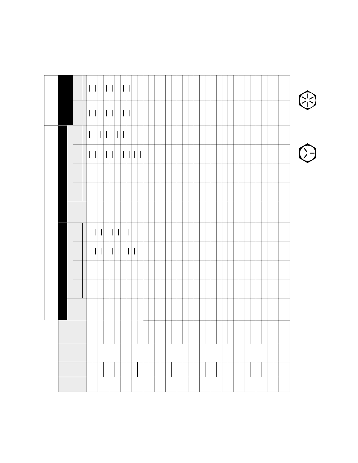
Table 1-6. Lubrication Chart
SECTION 1 - SPECIFICATIONS
Components
Wheel Drive Hubs
1
Slave Cylinder (Rod)
2
Slave Cylinder (Barrel )
3
Platform Pivot
4
Rotating Column
5
(Optional)
Rotary Worm Gear
6
(Optional)
Platform Hinges
7
Platform Lat ch
8
Boom Chain Extension
9
Sheave
Swing Bearing
10
Number/Type
Lube Points
Capacity Lube
Level/Fill Plug 1.3 L. (1/2 full) EPGL
(SAE90)
Interval Hours
3 Months
150 hrs
6 Months
300 hrs
1 Year
600 hrs
2 Years
1200 hrs
Comments
X Check level every 150 hours; change @ 1200
hours
1 Grease Fitting A/R MPG X
1 Grease Fitting A/R MPG X Gain access through boom fly section.
1 Grease Fitting A/R MPG X
2 Grease Fittings A/R MPG X
N/A A/R MPG X Br ush on.
2 Grease Fittings A/R MPG X
N/A A/R EO X
1 Grease Fitting A/R MPG X Align access holes in mid and fly boom.
2 Grease Fittings A/R MPG X Remote Acc ess
Lift Cylinder (Barrel End)
11
Master Cylinder (B arrel
12
End)
Master Cylinder (R od
13
End)
1 Grease Fitting A/R MPG X Remote Access
1 Grease Fitting A/R MPG X Remote Access
1 Grease Fitting A/R MPG X
3120863 – JLG Lift – 1-7

SECTION 1 - SPECIFICATIONS
Table 1-6. Lubrication Chart
Components
Boom Chain Retract
14
Sheave
Boom Pivot Bushings
15
Engine Crankcase
16
Engine Oil Filter
17
Engine Coolant
18
Hydraulic Oil
19
Hydraulic Oil Return
20
Filters
Hydraulic Reservoir
21
Suction Filter
Tie Rod Ends
22
King Pins
23
Steer Cylinder (Rod
24
End)
Steer Cylinder (Barre l
25
End)
Wheel Bearings
26
Swing Drive Hub
27
Swing Bearing and
28
Pinion Gear Teeth
Axle Beam (Extendable
29
Axles)
Axle Lock Pin
30
(Extendable Axles)
Oscillating Axle Pivot
31
Oscillation Cylinder
32
Extend-A-Reach Pivot (If
33
Equipped)
Number/Type
Lube Points
Capacity Lube
Interval Hours
3 Months
150 hrs
6 Months
300 hrs
1 Year
600 hrs
2 Years
1200 hrs
Comments
1 Grease Fitting A/R MPG X
2 Grease Fittings A/R MoS
X
2
Fill Cap Refer to Engine Manual EO Check daily. Change in accordance wth
engine manual.
N/A N/A N/A Change in accordance with engine manual.
Radiator Cap Refer to Engine Manual Refer to engine manual for coolant specifica-
tions. Check daily with engine cold.
Fill Cap 56 gallons HO X Check daily. Change every 1200 hours.
N/A N/A N/A Check filter gauges for element construction
daily. Replace as necessary.
N/A N/A N/A X Replace filter element every 600 hours; clean
mesh as necessary.
2 Grease Fittings A/R MPG X
2 Grease Fittings A/R MPG X
1 Grease Fitting A/R MPG X
1 Grease Fitting A/R MPG X
N/A A/R MPG X Repack
Fill Plug 0.5 L. (1/2 Full) EPGL
(SAE90)
X Check oil level weekly; change every 600
hours
N/A A/R MPG X Apply by brush onto bearing and gear teeth
N/A A/R MPG X Apply by brush
N/A A/R MPG X Apply by brush
1 Grease Fitting A/R MPG X
2 Grease Fittings A/R MPG X
2 Grease Fittings A/R MPG X
Extend-A-Reach Lift
34
Cylinder (Barrel End)
Extend-A-Reach Lift
35
Cylinder (Ro d End)
1 Grease Fitting A/R MPG X
1 Grease Fitting A/R MPG X
1-8 – JLG Lift – 3120863
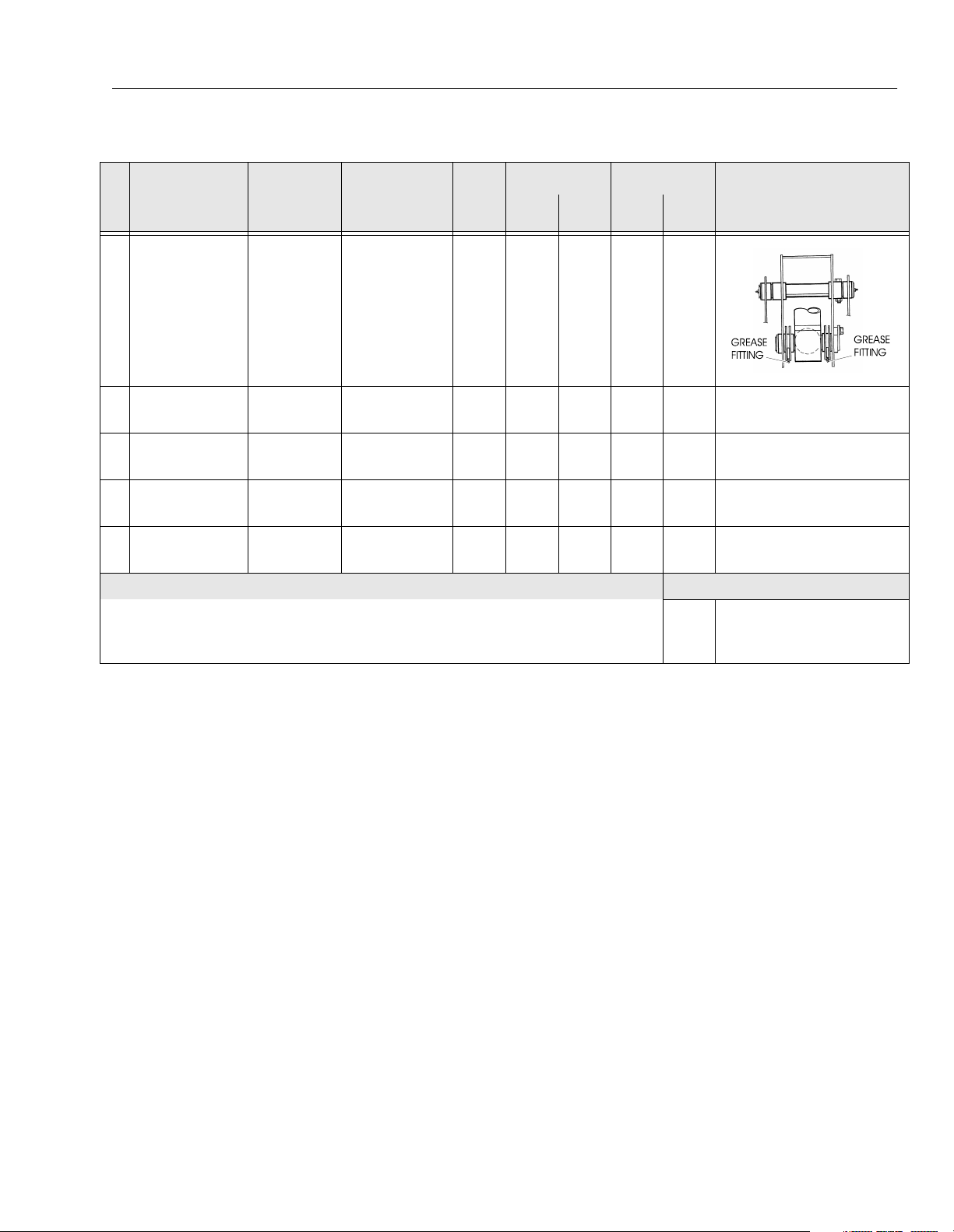
Table 1-6. Lubrication Chart
SECTION 1 - SPECIFICATIONS
Interval Hours
3 Months
150 hrs
6 Months
300 hrs
1 Year
600 hrs
2 Years
1200 hrs
Comments
Components
Extend-A-Reach - Boom
36
End (If Equipped)
Extend-A-Reach -
37
Platform End (if
Equipped)
Extend-A-Reach - Slave
38
Cylinder Rod End (If
Equipped)
Extend-A-Reach Link -
39
Slave Cylinder Pivot
Point (If Eq uipped )
Extend-A-Reach Link -
40
Slave Cylinder Pivot
Point (If Eq uipped )
Number/Type
Lube Points
Capacity Lube
2 Grease Fittings A/R MPG X
1 Grease Fitting A/R MPG X
1 Grease Fittings A/R MPG X
1 Grease Fitting A/R MPG X
1 Grease Fitting A/R MPG X
NOTES: KEY TO LUBRICANTS
Lubrication intervals are based on machine operation under normal conditions. For machines used in multi shift operations and/or exposed to hostile environments or conditions, lubrication frequencies must be increased accordingly.
EPGL
Engine Oil
EO
Extreme Pres sure Gear Lube
Hydraulic Fluid (Mobil #424 or equivalent)
HO
Multi-Pu rpose Grease
MPG
3120863 – JLG Lift – 1-9

SECTION 1 - SPECIFICATIONS
1.6 PRESSURE SETTINGS
NOTE: All pressure are given in pounds per square inch
(psi), with the metric equivalent, Bar, in parentheses.
80 HX
Proportional Relief - Standard 220 Bar;
Prop. Tele 265 Bar.
Sequence (Load Sense) - 31 Bar.
Pressure Reducing (Pilot Press) - 38 Bar.
Drive - 214 Bar; Prop. Tele. 259 Bar.
Lift Up - 207 Bar.
Lift Down - 103 Bar
Swing - 103 Bar.
Telescope In - 207 Bar; Prop. Tele 259 Bar.
Tele Out - 103 Bar.
Solenoid Main Relief - 214 Bar.
2 Wheel Steer - 138 Bar; w/axle lift cyl. - 152 Bar
2 Wheel Steer w/4WD - 138 Bar; w/axle lift cyl. 152 Bar.
4 Wheel Steer - 138 Bar w/axle lift cyl. - 152 Bar.
Extend-A-Reach Up - 172 Bar.
Extend-A-Reach Down - 76 Bar.
80HX w/Oscillating Axle
Proportional Relief - Standard 220 Bar;
Prop. Tele 265 Bar.
Sequence (Load Sense) - 31 Bar.
Pressure Reducing (Pilot Press) - 38 Bar).
Drive - 214 Bar; Prop. Tele. 259 Bar.
Lift Up - 207 Bar.
Lift Down - 103 Bar
Swing - 103 Bar.
Telescope In - 207 Bar Prop. Tele 259 Bar.
Tele Out - 103 Bar.
Solenoid Main Relief - 214 Bar
2 Wheel Steer - 103 Bar
2 Wheel Steer w/4WD - 103 Bar.
4 Wheel Steer; Axle Lift Cyl. - 152 Bar.
Extend-A-Reach Up - 172 Bar
Extend-A-Reach Down - 76 Bar
NOTE: Refer to Section 2 for pressure setting procedures.
Extend-A-Reach Down - 76 Bar.
80HX w/Hydraulic Controls
Proportional Relief - Standard 220 Bar;
Prop. Tele 265 Bar.
Sequence (Load Sense) - 28 to 41 Bar.
Pressure Reducing (Pilot Press) - 41 Bar.
Hyd. Controls Back Pressure - Relief 8.6 Bar;
Press. Red. 5.5 to 8.2 Bar
Drive - 214 Bar; Prop. Tele. 259 Bar.
Lift Up - 207 Bar.
Lift Down - 103 Bar
Swing - 103 Bar.
Telescope In - 207 Bar; Prop. Tele 259 Bar.
Tele Out - 103 Bar.
Solenoid Main Relief - 214 Bar
2 Wheel Steer - 138 Bar; w/axle lift cyl.- 152 Bar
2 Wheel Steer w/4WD - 138 Bar; w/axle lift cyl.- 152 Bar.
4 Wheel Steer - 138 Bar; w/axle lift cyl. - 152 Bar.
Extend-A-Reach Up - 172 Bar.
1-10 – JLG Lift – 3120863

SECTION 1 - SPECIFICATIONS
1.7 MAJOR COMPONENTS WEIGHTS
Table 1-7. Major Component Weights
Component Lbs. KG.
Platform w/o Control Box
Boom (includes Lif t Cylinder, Rotator, and Support)
Turntable Complete (includes E ngine)
Frame Complete (in cludes Tires and Wheels)
Complete Machine - 2WD No Options
Complete Machine - 4WD No Options
Complete Machine (80 HX+6) 2WD No Options
236
4816
14972
9290
28605
29106
31856
107
2184
6790
4213
12973
13200
14447
1.8 CYLINDER SPECIFICATIONS
Table 1-8. Cylinder Specifications
DESCRIPTION BORE STROKE ROD DIA.
Master Level 63.5 mm 387 mm 31.75 mm
Slave Level 63.5 mm 387 mm 31.75 mm
Lift 203 mm 781 mm 89 mm
Lockout
(Oscillating Axle)
Lockout
(4WD)
Telescope 89 mm 6551 mm 63.5 mm
Steer (2WD) 76 mm 205 mm 31.75 mm
Steer (4WD) 76 mm 249 mm 38 mm
102 mm 124 mm 31.75 mm
102 mm 108 mm 31.75 mm
1.9 BOOM TAPE
Red - 99 cm.
Yellow - 86.4 cm.
Blue - 492.5 cm.
1.10 CRITICAL STABILITY WEIGHTS
Table 1-9. Critical Stability Weights
Component Lb.s KG.
Engines
Tire & Wheels
Deutz F4L912
Ford LRG 423
Cummins 4B3.9
15x19.5 Tire
Wheel
Foam Fill
837 380
410 186
680 309
130 59
72 33
320 145
Extend-A-Reach
Lift 76 mm 322 mm 51 mm
Slave 89 mm 184 mm 44.5 mm
3120863 – JLG Lift – 1-11

SECTION 1 - SPECIFICATIONS
1.11 SERIAL NUMBER LOCATION
A serial number plate is affixed to the left rear front of the
turntable. If the serial number plate is damaged or missing, the machine serial number is stamped on the left side
of the frame between front and rear wheels, below turnta-
ble bearing. In addition, the last five digits of the serial
number are stamped on top of the fly, mid and base end
of the boom and on the left side of the turntable.
Figure 1-3. Serial Number Locations
1-12 – JLG Lift – 3120863

SECTION 2. PROCEDURES
SECTION 2 - PROCEDURES
2.1 GENERAL
This section provides information necessary to perform
maintenance on the aerial platform. Descriptions, techniques and specific procedures are designed to provide
the safest and most efficient maintenance for use by personnel responsible for ensuring the correct installation
and operation of machine components and systems.
WHEN AN ABNORMAL CONDITION IS NOTED AND PROCEDURES
CONTAINED HEREIN DO NOT SPECIFICALLY RELATE TO THE
NOTED IRREGULARITY, WORK SHOULD BE STOPPED AND
TECHNICALLY QUALIFIED GUIDANCE OBTAINED BEFORE WORK
IS RESUMED.
The maintenance procedures included consist of servicing and component removal and installation, disassembly
and assembly, inspection, lubrication and cleaning. Information on any special tools or test equipment is also provided where applicable.
2.2 SERVICING AND MAINTENANCE GUIDELINES
General
2. At any time when air, fuel, or oil lines are disconnected, clear adjacent areas as well as the openings
and fittings themselves. As soon as a line or component is disconnected, cap or cover all openings to
prevent entry of foreign matter.
3. Clean and inspect all parts during servicing or maintenance, and assure that all passages and openings
are unobstructed. Cover all parts to keep them
clean. Be sure all parts are clean before they are
installed. New parts should remain in their containers until they are ready to be used.
Components Removal and Installation
1. Use adjustable lifting devices, whenever possible, if
mechanical assistance is required. All slings (chains,
cables, etc.) should be parallel to each other and as
near perpendicular as possible to top of part being
lifted.
2. Should it be necessary to remove a component on
an angle, keep in mind that the capacity of an eyebolt or similar bracket lessens, as the angle between
the supporting structure and the component
becomes less than 90 degrees.
3. If a part resists removal, check to see whether all
nuts, bolts, cables, brackets, wiring, etc., have been
removed and that no adjacent parts are interfering.
The following information is provided to assist you in the
use and application of servicing and maintenance procedures contained in this chapter.
Safety and Workmanship
Your safety, and that of others, is the first consideration
when engaging in the maintenance of equipment. Always
be conscious of weight. Never attempt to move heavy
parts without the aid of a mechanical device. Do not allow
heavy objects to rest in an unstable position. When raising
a portion of the equipment, ensure that adequate support
is provided.
Cleanliness
1. The most important single item in preserving the
long service life of a machine is to keep dirt and foreign materials out of the vital components. Precautions have been taken to safeguard against this.
Shields, covers, seals, and filters are provided to
keep air, fuel, and oil supplies clean; however, these
items must be maintained on a scheduled basis in
order to function properly.
Component Disassembly and Reassembly
When disassembling or reassembling a component, complete the procedural steps in sequence. Do not partially
disassemble or assemble one part, then start on another.
Always recheck your work to assure that nothing has been
overlooked. Do not make any adjustments, other than
those recommended, without obtaining proper approval.
Pressure-Fit Parts
When assembling pressure-fit parts, use an “anti-seize” or
molybdenum disulfide base compound to lubricate the
mating surface.
3120863 – JLG Lift – 2-1

SECTION 2 - PROCEDURES
Bearings
1. When a bearing is removed, cover it to keep out dirt
and abrasives. Clean bearings in nonflammable
cleaning solvent and allow to drip dry. Compressed
air can be used but do not spin the bearing.
2. Discard bearings if the races and balls (or rollers)
are pitted, scored, or burned.
3. If bearing is found to be serviceable, apply a light
coat of oil and wrap it in clean (waxed) paper. Do not
unwrap reusable or new bearings until they are
ready to install.
4. Lubricate new or used serviceable bearings before
installation. When pressing a bearing into a retainer
or bore, apply pressure to the outer race. If the bearing is to be installed on a shaft, apply pressure to the
inner race.
Gaskets
Check that holes in gaskets align with openings in the
mating parts. If it becomes necessary to hand-fabricate a
gasket, use gasket material or stock of equivalent material
and thickness. Be sure to cut holes in the right location, as
blank gaskets can cause serious system damage.
Bolt Usage and Torque Application
Hydraulic System
1. Keep the system clean. If evidence of metal or rubber particles are found in the hydraulic system, drain
and flush the entire system.
2. Disassemble and reassemble parts on clean work
surface. Clean all metal parts with non-flammable
cleaning solvent. Lubricate components, as
required, to aid assembly.
Lubrication
Service applicable components with the amount, type,
and grade of lubricant recommended in this manual, at
the specified intervals. When recommended lubricants are
not available, consult your local supplier for an equivalent
that meets or exceeds the specifications listed.
Battery
Clean battery, using a non-metallic brush and a solution of
baking soda and water. Rinse with clean water. After
cleaning, thoroughly dry battery and coat terminals with
an anti corrosion compound.
Lubrication and Servicing
Components and assemblies requiring lubrication and
servicing are shown in Section 1.
1. Use bolts of proper length. A bolt which is too long
will bottom before the head is tight against its related
part. If a bolt is too short, there will not be enough
thread area to engage and hold the part properly.
When replacing bolts, use only those having the
same specifications of the original, or one which is
equivalent.
2. Unless specific torque requirements are given within
the text, standard torque values should be used on
heat-treated bolts, studs, and steel nuts, in accordance with recommended shop practices. (See the
Torque Chart in Section 1)
Hydraulic Lines and Electrical Wiring
Clearly mark or tag hydraulic lines and electrical wiring, as
well as their receptacles, when disconnecting or removing
them from the unit. This will assure that they are correctly
reinstalled.
2.3 LUBRICATION INFORMATION
Hydraulic System
1. The primary enemy of a hydraulic system is contamination. Contaminants enter the system by various
means, e.g., using inadequate hydraulic oil, allowing
moisture, grease, filings, sealing components, sand,
etc., to enter when performing maintenance, or by
permitting the pump to cavitate due to insufficient
system warm-up or leaks in the pump supply (suction) lines.
2. The design and manufacturing tolerances of the
component working parts are very close, therefore,
even the smallest amount of dirt or foreign matter
entering a system can cause wear or damage to the
components and generally results in faulty operation. Every precaution must be taken to keep
hydraulic oil clean, including reserve oil in storage.
Hydraulic system filters should be checked,
cleaned, and/or replaced as necessary, at the specified intervals required in Section 1. Always examine
filters for evidence of metal particles.
2-2 – JLG Lift – 3120863

SECTION 2 - PROCEDURES
3. Cloudy oils indicate a high moisture content which
permits organic growth, resulting in oxidation or corrosion. If this condition occurs, the system must be
drained, flushed, and refilled with clean oil.
4. It is not advisable to mix oils of different brands or
types, as they may not contain the same required
additives or be of comparable viscosities. Good
grade mineral oils, with viscosities suited to the
ambient temperatures in which the machine is operating, are recommended for use.
NOTE: Metal particles may appear in the oil or filters of new
machines due to the wear-in of meshing components.
Hydraulic Oil
1. Refer to Section 1 for recommendations for viscosity
ranges.
2. JLG recommends Mobilfluid 424 hydraulic oil, which
has an SAE viscosity of 10W-20 and a viscosity
index of 152, or BP Energol SHS46.
NOTE: Start-up of hydraulic system with oil temperatures
below -26° C (-15° F). is not recommended. If it is
necessary to start the system in a sub-zero environment, it will be necessary to heat the oil with a low
density, 100VAC heater to a minimum temperature of
-26° C (-15° F).
2. Use every precaution to keep the hydraulic oil clean.
If the oil must be poured from the original container
into another, be sure to clean all possible contaminants from the service container. Always clean the
mesh element of the filter and replace the cartridge
any time the system oil is changed.
3. While the unit is shut down, a good preventive maintenance measure is to make a thorough inspection
of all hydraulic components, lines, fittings, etc., as
well as a functional check of each system, before
placing the machine back in service.
Lubrication Specifications
Specified lubricants, as recommended by the component
manufacturers, are always the best choice, however,
multi-purpose greases usually have the qualities which
meet a variety of single purpose grease requirements.
Should any question arise, regarding the use of greases in
maintenance stock, consult your local supplier for evaluation. Refer to Section 1 for an explanation of the lubricant
key designations appearing in the Lubrication Chart.
3. The only exception to the above is to drain and fill
the system with Mobil DTE 11 oil or its equivalent.
This will allow start up at temperatures down to -29°
C (-20°F). However, use of this oil will give poor per-
formance at temperatures above 49° C (120° F). Sys-
tems using DTE 11 oil should not be operated at
temperatures above 93° C (200°F). under any condition.
Changing Hydraulic Oil
1. Use of any of the recommended crankcase or
hydraulic oils eliminates the need for changing the
oil on a regular basis. However, filter elements must
be changed after the first 40 hours of operation and
every 250 hours thereafter. If it is necessary to
change the oil, use only those oils meeting or
exceeding the specifications appearing in this manual. If unable to obtain the same type of oil supplied
with the machine, consult local supplier for assistance in selecting the proper equivalent. Avoid mixing petroleum and synthetic base oils. JLG
Industries recommends changing the hydraulic oil
annually.
3120863 – JLG Lift – 2-3

SECTION 2 - PROCEDURES
2.4 CYLINDERS - THEORY OF OPERATION
Double Acting Cylinders
Cylinders are of the double-acting type. Systems incorporating double-acting cylinders are as follows: Lift, Telescope, Platform Leveling, Steer and Lockout. A double
acting cylinder is one that requires oil flow to operate the
cylinder rod in both directions. Directing oil (by actuating
the corresponding control valve to the piston side of the
cylinder) forces the piston to travel toward the rod end of
the barrel, extending the cylinder rod (piston attached to
rod). When the oil flow is stopped, movement of rod will
stop. By directing oil to the rod side of the cylinder, the
piston will be forced in the opposite direction and the cylinder rod will retract.
2.5 VALVES - THEORY OF OPERATION
Holding Valves
Holding Valves are used in the Lift, Telescope, Slave Level
and lockout circuits to prevent retraction of the cylinder
rod, should a hydraulic line rupture or a leak develop
between the cylinder and its related control valve.
Solenoid Control Valves (Bang-Bang)
Control valves used are four-way three-position solenoid
valves of the sliding spool design. When a circuit is activated and the control valve solenoid energizes, the spool
is shifted and the corresponding work port opens to permit oil flow to the component in the selected circuit with
the opposite work port opening to reservoir. Once the circuit is deactivated (control returned to neutral) the valve
spool returns to neutral (center) and oil flow is then
directed through the valve body and returns to reservoir. A
typical control valve consist of the valve body, sliding
spool, and two solenoid assemblies. The spool is
machine fitted in the bore of the valve body. Lands on the
spool divide the bore into various chambers, which when
the spool is shifted, align with corresponding ports in the
valve body open to common flow. At the same time other
ports would be blocked to flow. The spool is spring loaded
to center position, therefore when the control is released,
the spool automatically returns to neutral, prohibiting any
flow through the circuit.
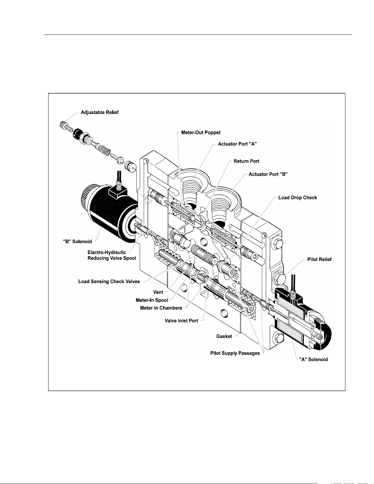
Proportional Control Valve - Vickers (See
Figure 2-1)
CMX series valves provide a power output matching that
required by the load. A small line connected to a loadsensing port feeds load pressure back to the pump. The
pump senses the difference between the load and pump
outlet pressures, and varies the pump displacement to
keep the difference constant. This differential pressure is
applied across the valves meter-in spool, with the effect
that pump flow is determined by the degree of spool
opening, independent of load pressure. Return lines are
connected together simplifying routing of return flow and
to help reduce cavitation. Load sensing lines connect
through shuttle valves to feed the highest load signal back
to the pump. Integral actuator port relief valves, anti-cavitation check valves, and load check valves are standard.
The load drop check prevents any drop of a suspended
load before upward movement.
Main Relief Valves
Main relief valves are installed at various points with the
hydraulic system to protect associated systems and components against excessive pressure. Excessive pressure
can be developed when a cylinder reaches its limit of
travel and the flow of pressurized fluid continues from the
system control. The relief valve provides an alternate path
for the continuing flow from the pump, thus preventing
rupture of the cylinder, hydraulic line or fitting. Complete
failure of the system pump is also avoided by relieving circuit pressure. The relief valve is installed in the circuit
between the pump outlet (pressure line) and the cylinder
of the circuit, generally as an integral part of the system
valve bank. Relief pressures are set slightly higher than
the load requirement, with the valve diverting excess
pump delivery back to the reservoir when operating pressure of the component is reached.
Relief Valves
Crossover relief valves are used in circuits where the actuator requires an operating pressure lower than that supplied to the system. When the circuit is activated and the
required pressure at the actuator is developed, the crossover relief diverts excess pump flow to the reservoir, individual, integral reliefs are provided for each side of the
circuits.
2-4 – JLG Lift – 3120863
SECTION 2 - PROCEDURES
Figure 2-1. Proportional Control Valve
3120863 – JLG Lift – 2-5

SECTION 2 - PROCEDURES
Figure 2-2. Typical Boom Assembly
2.6 BOOM CHAINS (SEE FIGURE 2-2.)
Adjusting Procedures
ENSURE THE MACHINE IS ON A FIRM AND LEVEL SURFACE.
1. Fully retract the boom in the horizontal position (±
5°) with no load in the platform.
2. Extend the platform approximately 1 meter (3 ft.).
3. Torque the boom retract chain adjuster to 69 NM (50
ft. lbs.), then torque the boom extend chain adjuster
to 69 NM (50 ft. lbs.).
4. Retract the platform approximately 0.3 m (1 ft.).
5. Check the boom extend chain adjusters (69 NM {50
ft. lbs.} required).
6. Retract the platform approximately 0.3 m (1 ft.) once
again.
7. Recheck the extend chain adjusters (69 NM {50 ft.
lbs.} required).
8. Extend the platform approximately 0.3 m (1 ft.).
Check for proper operation of boom.
9. Recheck the retract chain adjuster torque. (69 NM
{50 ft. lbs.} required).
10. Fully extend and retract the boom and check for
proper operation.
JLG Industries, Inc. requires a complete boom disassembly, per instructions outlined in Section 2.12, Boom Maintenance, every two years. All boom chains and related
components (i.e., sheaves, pins, sprockets, wear pads,
etc.) must also be inspected and replaced (as necessary)
during this disassembly.
An immediate disassembly of the boom assembly and
inspection of the boom chains and related components is
required if any of the following conditions occur:
1. After the machine is exposed to hostile environments or conditions (i.e. extreme cold, dust, sand,
blasting grit, salt, chemicals, etc.), which could
adversely affect boom operation.
2. Erratic boom operation or unusual noise exists. See
the Troubleshooting section in this Service Manual.
3. Chain adjustment is required more often than specified in the Preventive Maintenance and Inspection
Schedule in this Service Manual or links need to be
removed (chain shortened) to make the proper
adjustment.
4. The machine is idle for an extended period (6
months or longer.)
5. The boom is overloaded or sustained a shock load.
2-6 – JLG Lift – 3120863

FAILURE TO DISASSEMBLE THE BOOM ASSEMBLY AND PROPERLY INSPECT AND/OR REPLACE THE BOOM CHAINS AND
RELATED COMPONENTS (I.E., SHEAVES, PINS, SPROCKETS,
WEAR PADS, ETC.) COULD RESULT IN THE DAMAGE AND/OR
BREAKAGE OF THE BOOM CHAINS AND/OR RELATED COMPONENTS. DAMAGE AND/OR BREAKAGE OF THESE ITEMS COULD
RESULT IN UNCONTROLLED EXTENSION OR RETRACTION OF
THE BOOM ASSEMBLY AND COULD CAUSE SERIOUS INJURY OR
DEATH TO PERSONNEL OPERATING THE JLG BOOM LIFT.
Inspection Procedures
Inspect boom chains for the following condition:
1. Wear: Always inspect that segment of chain that
operates over a sheave. As the chain flexes over the
extend/retract sheaves, joints and plate edges very
gradually wear. Chain “stretch” can be measured
using a manufacturers wear scale or steel tape.
When chains have elongated 3% they must be
removed and replaced. Refer to Table 2-1 for proper
chain specifications and allowable stretch tolerances. Peening and wear of chain plate edges are
caused by sliding over a chain worn contact face of
a sheave, or unusually heavy loads. All of the above
require replacement of the chain and correction of
the cause. Chain side wear, noticeable when pin
heads and outside plates show a definite wear pattern, is caused by misalignment of the sheave/chain
anchors and must be corrected promptly. Do not
repair chains; if a section of chain is damaged,
replace the entire chain set.
SECTION 2 - PROCEDURES
NOTE: The need for lubrication can be determined by the
presence of rust on the exposed portions of chain.
3. Rust and Corrosion: Rust and corrosion will cause
a major reduction in the load carrying capacity of the
chain, because these are primary reasons for side
plate cracking. The initial lubrication at the factory is
applied in a hot dip tank to assure full penetration
into the joint. Do not steam clean or degrease this
lubricant on chains. A grade of SAE 30 or 40 weight,
non detergent motor oil should be used as a supplemental lubricant and a film of this oil should be constantly maintained on the surfaces and internal
joints. At time of chain installation, factory lube must
be supplemented by a maintenance program to provide a film of oil on the chains at all times. If chains
are corroded, they must be inspected, especially the
outside plates, for cracks in-line with the pins. If
cracks are found, replace the chain; if no cracks are
discovered, lubricate the chains by dipping in
heated oil, and reinstall on the machine. Keep
chains lubricated.
4. Fatigue Cracks: Fatigue is a phenomenon that
affects most metals, and is the most common cause
of chain plate failures. Fatigue cracks are found
through the link holes, perpendicular (90 degrees)
from the pin in-line position. Inspect chains carefully
after long time use and heavy loading for this type of
crack. If any cracks are discovered, replace all
chains, as seemingly sound plates are on the verge
of cracking. Fatigue and ultimate strength failures on
JLG Lifts are incurred as a result of severe abuse as
design specs are well within the rated lifting capacity
of these chains.
5. Tight Joints: All joints in the roller chain should flex
2. Lubrication: One of the most important but often
overlooked factors is adequate lubrication. In addition to reducing internal friction, maintaining a film of
oil on all chain surfaces will inhibit rusting and corrosion. This is important as corrosion of highly
stressed, hardened steel chain components can
cause a major reduction in the load capacity of leaf
chain and result in link plate cracking.
freely. On roller chain, tight joints are usually caused
by rust/corrosion, or the inside plates “walking” off
the bushing. Limber up rusty/corroded chains (after
inspecting care fully) with a heavy application of oil
(preferably a hot oil dip). Tap inside “walking” plates
inward; if “walking” persists, replace the chain. This
type of problem is accelerated by poor lubrication
maintenance practice, and most tight joint chains
have been operated with little or no lubrication. Tight
joints on leaf chain are generally caused by:
1. Bent pins or plates.
2. Rusty joints.
3. Peened plate edges.
3120863 – JLG Lift – 2-7

SECTION 2 - PROCEDURES
ARC-LIKE CRACKED PLATES
(STRESS CORROSION)
Oil rusty chains, and replace chains with bent or peened
chain components. Keep chains lubricated.
TIGHT JOINTS
6. Protruding or Turned Pins: Chains operating with
inadequate lube generate tremendous friction
between the pin and plates (pin and bushing on
roller chain). In extreme cases, this frictional torque
can actually turn the pins in the outside press-fit
plates. Inspect for turned pins, which can be easily
spotted as the “V” flats on the pin heads are no
longer in line. Replace all chains showing evidence
of turned or protruding pins. Keep chains lubricated.
7. Stress Corrosion Cracking: The outside link
plates, which are heavily press-fitted to the pins, are
particularly susceptible to stress corrosion cracking.
Like fatigue cracks, these initiate at the point of highest stress (aperture) but tend to extend in an arc-like
path, often parallel to the rolling grain of the material.
ABNORMAL PROTRUSION OR
TURNED PINS
Anchors with worn or broken fingers should be
replaced. They should also be adjusted to eliminate
twisting the chain for an even load distribution.
Sheaves should be inspected for worn flanges, which
would indicate misalignment, and wear on the outside
diameter of the sheave. A worn sheave can mean several
problems, as follows:
1. Chains too tight.
2. Sheave bearings/pin bad.
3. Bent/misaligned chains.
.
Table 2-1. Chain Stretch Tolerance
ALLOWABLE
STRETCH 14 IN.
SPAN
1.07 cm
1.07 cm
1.07 cm
CHAIN SIZE
0.50 in. (1.27 cm)
pitch
1.00 in. (2.54 cm)
pitch
1.75 in. (4.45 cm)
pitch
PIN TO PIN
MEASUREMENT
36 cm or 28
pitches
36 cm or 14
pitches
36 cm or 8
pitches
Also, more then one crack can often appear on a
link plate. In addition to rusting, this condition can
be caused by exposure to an acidic or caustic
medium or atmosphere. Stress corrosion is an environmentally assisted failure. Two conditions must be
present; corrosive agent and static stress.
In the chain, static stress is present at the aperture
due to the press fit pin. No cycle motion is required
and the plates can crack during idle periods. The
reactions of many chemical agents (such as battery
acid fumes) with hardened metals liberate hydrogen
which attacks and weakens the metal grain structure.
8. Chain Anchors, Sheaves and Pins: An inspection
of the chain must include a close examination of
chain anchors, sheaves and pins. Check chain
anchors for wear breakage and misalignment.
2-8 – JLG Lift – 3120863
2.00 in. (5.08 cm)
pitch
36 cm or 7
pitches
1.07 cm
Auxiliary Boom Chains
The auxiliary boom chains are used as a safety device, to
prevent the boom from retracting in the event that an
extend chain should break. As the boom would begin to
retract, tension would be placed on the auxiliary chain,
stopping the boom and tripping a limit switch to shut
down the machine.
The auxiliary boom chain is located on top of the boom.
One end of the chain is attached to an adjustable clevis on
top of the front end of the base section, and uses belleville
washers and adjusting nuts to adjust chain tension. The
other end of the chain is attached to a fixed clevis on top
of the fly section. A limit switch is installed adjacent to the
adjustable clevis on the base section, and when tripped,
shuts down the machine. Adjust chain tension so there is
no slack in the chain and set the cam on the switch so the
switch trips when the belleville washers compress 1 to 1.3
cm.
REPLACE THE BELLEVILLE WASHERS ONCE THEY HAVE BEEN
COMPRESSED.
 Loading...