


Operation and Safety Manual
®
Original Instructions - Keep this manual with the machine at all times.
Model(s)
AM Series
20AM
25AM
30AM
ANSI
36AM
41AM
P/N - 3121211
November 12, 2014

NOTES:

FOREWORD
FOREWARD
This manual is a very important tool! Keep it with the machine at all times.
The purpose of this manual is to provide owners, users, operators, lessors, and lessees with the precautions and
operating procedures essential for the safe and proper machine operation for its intended purpose.
Due to continuous product improvements, JLG Industries, Inc. reserves the right to make specification changes
without prior notification. Contact JLG Industries, Inc. for updated information.
3121211 – JLG Lift – a

FOREWORD
DANGER
CAUTION
NOTICE
SAFETY ALERT SYMBOLS AND SAFETY SIGNAL WORDS
This is the Safety Alert Symbol. It is used to alert you to the potential personal
injury hazards. Obey all safety messages that follow this symbol to avoid possible injury or death
INDICATES AN IMMINENTLY HAZARDOUS SITUATION. IF NOT
AVOIDED, WILL
RESULT IN SERIOUS INJURY OR DEATH. THIS DECAL
WILL HAVE A RED BACKGROUND.
INDICATES A POTENTIALITY HAZARDOUS SITUATION. IF NOT
AVOIDED, MAY
RESULT IN MINOR OR MODERATE INJURY. IT MAY
ALSO ALERT AGAINST UNSAFE PRACTICES. THIS DECAL WILL HAVE A
YELLOW BACKGROUND.
INDICATES A POTENTIALITY HAZARDOUS SITUATION. IF NOT
AVOIDED, COULD
RESULT IN SERIOUS INJURY OR DEATH. THIS DECAL
WILL HAVE AN ORANGE BACKGROUND.
INDICATES INFORMATION OR A COMPANY POLICY THAT RELATES
DIRECTLY OR INDIRECTLY TO THE SAFETY OF PERSONNEL OR PROTECTION OF PROPERTY.
b – JLG Lift – 3121211

THIS PRODUCT MUST COMPLY WITH ALL SAFETY RELATED BULLE-
NOTICE
NOTICE
TINS. CONTACT JLG INDUSTRIES, INC. OR THE LOCAL AUTHORIZED
JLG REPRESENTATIVE FOR INFORMATION REGARDING SAFETY
RELATED BULLETINS WHICH MAY HAVE BEEN ISSUED FOR THIS
PRODUCT.
JLG INDUSTRIES, INC. SENDS SAFETY RELATED BULLETINS TO THE
OWNER OF RECORD OF THIS MACHINE. CONTACT JLG INDUSTRIES,
INC. TO ENSURE THAT THE CURRENT OWNER RECORDS ARE UPDATED
AND ACCURATE.
For :
• Accident Reporting
•Product Safety Publications
•Current Owner
Updates
• Questions Regarding
Product Safety
• Standards and Regulations Compliance Information
• Questions Regarding Special Product Applications
• Questions Regarding
Product Modifications
Contact :
Product Safety and Reliability Department
JLG Industries, Inc.
1 JLG Drive
McConnellsburg, PA 17233
FOREWORD
JLG INDUSTRIES, INC. MUST BE NOTIFIED IMMEDIATELY IN ALL
INSTANCES WHERE JLG PRODUCTS HAVE BEEN INVOLVED IN AN ACCIDENT INVOLVING BODILY INJURY OR DEATH OF PERSONNEL OR
WHEN SUBSTANTIAL DAMAGE HAS OCCURRED TO PERSONAL PROPERTY OR THE JLG PRODUCT.
or Your Local JLG Office
(See addresses on manual rear cover)
In USA:
Toll Free: 877-JLG-SAFE (877-554-7233)
Outside USA:
3121211 – JLG Lift – c
Phone: 717-485-5161
E-mail: ProductSafety@JLG.com

FOREWORD
REVISION LOG
Original Issue of Manual . . . . . . . . . . . . . . . . . . . . . . . . July 6, 2005
Manual Revised . . . . . . . . . . . . . . . . . . . . . . . . . . . . . . June 30, 2006
Manual Revised . . . . . . . . . . . . . . . . . . . . . . . . . . . . . . . June 4, 2007
Manual Revised . . . . . . . . . . . . . . . . . . . . . . . . . . . . . . . . May 5, 2008
Manual Revised . . . . . . . . . . . . . . . . . . . . . . . . . . . . January 5, 2010
Manual Revised . . . . . . . . . . . . . . . . . . . . . . . . . . . . . . June 14, 2010
Manual Revised . . . . . . . . . . . . . . . . . . . . . . . . November 12, 2014
d – JLG Lift – 3121211

TABLE OF CONTENTS
SECTION - PARAGRAPH, SUBJECT PAGE SECTION - PARAGRAPH, SUBJECT PAGE
SECTION - 1 - SAFETY PRECAUTIONS
1.1 GENERAL. . . . . . . . . . . . . . . . . . . . . . . . . . . . . . . . . . . . . . .1-1
1.2 TRANSPORTING . . . . . . . . . . . . . . . . . . . . . . . . . . . . . . . . 1-1
Transport . . . . . . . . . . . . . . . . . . . . . . . . . . . . . . . . . . . 1-1
Tipping Hazards. . . . . . . . . . . . . . . . . . . . . . . . . . . . . 1-2
Tilt Back Procedure . . . . . . . . . . . . . . . . . . . . . . . . . . 1-4
1.3 PRE-OPERATION. . . . . . . . . . . . . . . . . . . . . . . . . . . . . . . . 1-5
General . . . . . . . . . . . . . . . . . . . . . . . . . . . . . . . . . . . . . 1-5
Electrocution Hazard . . . . . . . . . . . . . . . . . . . . . . . . 1-6
1.4 OPERATION . . . . . . . . . . . . . . . . . . . . . . . . . . . . . . . . . . . . 1-7
1.5 MAINTENANCE SAFETY PRECAUTIONS . . . . . . . . .1-10
SECTION - 2 - USER RESPONSIBILITIES, MACHINE
PREPARATION, AND INSPECTION
2.1 PERSONNEL TRAINING. . . . . . . . . . . . . . . . . . . . . . . . . . 2-1
Operator Training . . . . . . . . . . . . . . . . . . . . . . . . . . . 2-1
Training Supervision . . . . . . . . . . . . . . . . . . . . . . . . 2-1
Operator Responsibility . . . . . . . . . . . . . . . . . . . . . 2-1
2.2 PREPARATION, INSPECTION, AND
MAINTENANCE . . . . . . . . . . . . . . . . . . . . . . . . . . . . . . . . .2-2
2.3 PRE-START INSPECTION. . . . . . . . . . . . . . . . . . . . . . . . . 2-4
3121211 – JLG Lift – i
2.4 FUNCTION CHECK . . . . . . . . . . . . . . . . . . . . . . . . . . . . . 2-5
2.5 DAILY WALK-AROUND INSPECTION. . . . . . . . . . . . . 2-5
General. . . . . . . . . . . . . . . . . . . . . . . . . . . . . . . . . . . . . . 2-5
SECTION - 3 - MACHINE CONTROLS AND INDICATORS
3.1 GENERAL . . . . . . . . . . . . . . . . . . . . . . . . . . . . . . . . . . . . . . 3-1
3.2 CONTROLS AND INDICATORS . . . . . . . . . . . . . . . . . . 3-1
Ground Control Station . . . . . . . . . . . . . . . . . . . . . . 3-1
Manual Descent Valve . . . . . . . . . . . . . . . . . . . . . . . 3-3
Platform Control Station . . . . . . . . . . . . . . . . . . . . . 3-3
3.3 DECAL INSTALLATIONS . . . . . . . . . . . . . . . . . . . . . . . . 3-5
SECTION - 4 - MACHINE OPERATION
4.1 DESCRIPTION . . . . . . . . . . . . . . . . . . . . . . . . . . . . . . . . . . 4-1
4.2 OPERATING CHARACTERISTICS AND
LIMITATIONS . . . . . . . . . . . . . . . . . . . . . . . . . . . . . . . . . . 4-1
Capacities . . . . . . . . . . . . . . . . . . . . . . . . . . . . . . . . . . . 4-1
4.3 BATTERY CHARGING & MAINTENANCE -
(DC MODELS ONLY) . . . . . . . . . . . . . . . . . . . . . . . . . . . . 4-2
Battery Maintenance and Safety . . . . . . . . . . . . . . 4-2
Battery Charger Operation . . . . . . . . . . . . . . . . . . . 4-3
Abnormal Cycle Indicator LED. . . . . . . . . . . . . . . . 4-4

TABLE OF CONTENTS
SECTION - PARAGRAPH, SUBJECT PAGE SECTION - PARAGRAPH, SUBJECT PAGE
4.4 MACHINE SET-UP AND OPERATION. . . . . . . . . . . . . .4-5
Caster Brake Operation . . . . . . . . . . . . . . . . . . . . . . 4-5
Outrigger Installation. . . . . . . . . . . . . . . . . . . . . . . . 4-6
Platform Loading . . . . . . . . . . . . . . . . . . . . . . . . . . . . 4-8
Platform Operation . . . . . . . . . . . . . . . . . . . . . . . . . . 4-8
4.5 QUICK-CHANGE PLATFORM MOUNTS. . . . . . . . . . .4-9
Platform Removal . . . . . . . . . . . . . . . . . . . . . . . . . . . 4-9
Platform Installation . . . . . . . . . . . . . . . . . . . . . . . . 4-10
4.6 MACHINE SHUT DOWN AND PARK . . . . . . . . . . . . 4-10
4.7 TRANSPORT, LIFTING AND TIE DOWN. . . . . . . . . . 4-11
General . . . . . . . . . . . . . . . . . . . . . . . . . . . . . . . . . . . . 4-11
Transporting by Pushing. . . . . . . . . . . . . . . . . . . . 4-11
Tilt-Back Assembly Set-up (AM36/AM41) -
Machines Prior to S/N - 0900031618 . . . . . . . . 4-11
Tilt-Back Assembly Set-up (AM36/AM41) -
Machines S/N - 0900031618 to Present . . . . . 4-15
Pickup Truck Loading Device (Option). . . . . . . 4-19
Lifting. . . . . . . . . . . . . . . . . . . . . . . . . . . . . . . . . . . . . . 4-23
Machine Tie Down. . . . . . . . . . . . . . . . . . . . . . . . . . 4-23
ii – JLG Lift – 3121211
SECTION - 5 - OPTIONAL EQUIPMENT
5.1 OPTIONAL EQUIPMENT. . . . . . . . . . . . . . . . . . . . . . . . . 5-1
22" x 25" Quick-Change Platform . . . . . . . . . . . . . 5-1
26" x 26" Quick-Change Platform . . . . . . . . . . . . . 5-1
28" x 26" Quick-Change Platform . . . . . . . . . . . . . 5-1
25" x 26" Step-in Molded Platform
w/Swing-up Gate . . . . . . . . . . . . . . . . . . . . . . . . . . . . 5-1
Tool Tray . . . . . . . . . . . . . . . . . . . . . . . . . . . . . . . . . . . . 5-1
Fluorescent Tube Caddy . . . . . . . . . . . . . . . . . . . . . 5-1
Crane Hook . . . . . . . . . . . . . . . . . . . . . . . . . . . . . . . . . . 5-1
Straddle Extension . . . . . . . . . . . . . . . . . . . . . . . . . . . 5-1
Ladder for Straddle Extension . . . . . . . . . . . . . . . . 5-1
Extra Power Pack (Battery, Charger & Case) . . . 5-2
Platform Auxiliary Power Lowering Device . . . . 5-2
Laser Positioning Device . . . . . . . . . . . . . . . . . . . . . 5-2
Hour Meter . . . . . . . . . . . . . . . . . . . . . . . . . . . . . . . . . . 5-2
Machine Cycle Counter Meter . . . . . . . . . . . . . . . . 5-2

TABLE OF CONTENTS
SECTION - PARAGRAPH, SUBJECT PAGE SECTION - PARAGRAPH, SUBJECT PAGE
5.2 AM-SE - STRADDLE EXTENSION –
INSTALLATION . . . . . . . . . . . . . . . . . . . . . . . . . . . . . . . . . 5-3
Description . . . . . . . . . . . . . . . . . . . . . . . . . . . . . . . . . 5-3
Straddle Adaptor Wiring Components . . . . . . . 5-3
Straddle Adaptor Wiring Installation . . . . . . . . . 5-3
AM-SE - Straddle Extension –
Set-up And Operation . . . . . . . . . . . . . . . . . . . . . . . . 5-7
Straddle Extension - Components. . . . . . . . . . . . 5-7
Mounting - Straddle Extension to AM . . . . . . . . 5-7
Positioning Straddle Unit and
Lifting AM Machine. . . . . . . . . . . . . . . . . . . . . . . . . . 5-9
Lowering AM Machine on Straddle Unit . . . . . 5-10
Straddle and AM Machine Disassembly . . . . . 5-11
SECTION - 6 - EMERGENCY PROCEDURES
6.1 GENERAL INFORMATION. . . . . . . . . . . . . . . . . . . . . . . . 6-1
6.2 EMERGENCY OPERATION . . . . . . . . . . . . . . . . . . . . . . . 6-1
Operator Unable to Control Machine. . . . . . . . . 6-1
Platform Caught Overhead . . . . . . . . . . . . . . . . . . 6-1
Righting of Tipped Machine . . . . . . . . . . . . . . . . . 6-1
6.3 INCIDENT NOTIFICATION . . . . . . . . . . . . . . . . . . . . . . . 6-2
3121211 – JLG Lift – iii
SECTION - 7 - GENERAL SPECIFICATIONS AND OPERATOR
MAINTENANCE
7.1 INTRODUCTION. . . . . . . . . . . . . . . . . . . . . . . . . . . . . . . . 7-1
7.2 GENERAL SPECIFICATIONS . . . . . . . . . . . . . . . . . . . . . 7-2
Machine Specifications . . . . . . . . . . . . . . . . . . . . 7-2
Electrical Specifications . . . . . . . . . . . . . . . . . . . . 7-3
Battery Specifications . . . . . . . . . . . . . . . . . . . . . . . 7-3
Platform Data . . . . . . . . . . . . . . . . . . . . . . . . . . . . 7-4
Machine Component Weights . . . . . . . . . . . . . 7-5
Serial Number Locations . . . . . . . . . . . . . . . . . . . . . 7-5
7.3 OPERATOR MAINTENANCE . . . . . . . . . . . . . . . . . . . . . 7-6
Lubrication . . . . . . . . . . . . . . . . . . . . . . . . . . . . . . . . . . 7-6
Battery Maintenance. . . . . . . . . . . . . . . . . . . . . . . . . 7-7
7.4 SUPPLEMENTAL INFORMATION . . . . . . . . . . . . . . . 7-10
SECTION - 8 - INSPECTION AND REPAIR LOG
LIST OF FIGURES
2-1. Daily Walk-Around inspection. . . . . . . . . . . . . . . . . . 2-7
3-1. Ground Control Station.. . . . . . . . . . . . . . . . . . . . . . . . 3-2
3-2. Manual Descent Valve Location.. . . . . . . . . . . . . . . . 3-3
3-3. Manual Descent Valve Location.. . . . . . . . . . . . . . . . 3-4
3-4. Platform Control Station.. . . . . . . . . . . . . . . . . . . . . . . 3-4

TABLE OF CONTENTS
SECTION - PARAGRAPH, SUBJECT PAGE SECTION - PARAGRAPH, SUBJECT PAGE
3-5. Decal Installation. (ANSI/CSA)
(Machines prior to S/N-0900031618) . . . . . . . . . . . .3-5
3-6. Decal Installation (CE)
(Machines prior to S/N-0900031618) . . . . . . . . . . . .3-8
3-7. Decal Installation. (ANSI/CSA)
(Machines S/N-0900031618 to Present). . . . . . . . 3-11
3-8. Decal Installation (CE)
(Machines S/N-0900031618 to Present). . . . . . . . 3-14
4-1. Battery Fluid Level. . . . . . . . . . . . . . . . . . . . . . . . . . . . . .4-2
4-2. Battery Box and Charger Assembly.
(D.C. Model Only) . . . . . . . . . . . . . . . . . . . . . . . . . . . . . . .4-3
4-3. Dual Voltage Charger - Front Panel. . . . . . . . . . . . . .4-4
4-4. Setting & Releasing Caster Brake . . . . . . . . . . . . . . . .4-5
4-5. Outrigger Installation. . . . . . . . . . . . . . . . . . . . . . . . . . .4-7
4-6. Quick Change Platform Mount. . . . . . . . . . . . . . . . . .4-9
4-7. Tilt-Back Assembly Set-Up. . . . . . . . . . . . . . . . . . . . . 4-12
4-8. Tilt-Back Assembly Set-Up -
Machines S/N - 0900031618 to Present. . . . . . . . 4-16
4-9. Tilt-Back Assembly Set-Up -
Machines S/N - 0900031618 to Present. . . . . . . . . . . . . . . 4-17
4-10. Tilt-Back Assembly Set-Up -
Machines S/N - 0900031618 to Present. . . . . . . . . . . . . . . 4-18
4-11. Loading Machine onto Bed of Pick-Up Truck. . . 4-20
5-1. Hour Meter Location. (Option) . . . . . . . . . . . . . . . . . .5-2
5-2. SE-Adapter - Wiring - Grommet & Spring Clip
Mounting Hole Locations.
(Same For Both Sides) . . . . . . . . . . . . . . . . . . . . . . . . . . 5-5
5-3. Straddle Adapter Wiring Harness to AM Wiring
Connections. . . . . . . . . . . . . . . . . . . . . . . . . . . . . . . . . . . 5-6
5-4. Straddle Extension Component Assembly. . . . . . . 5-8
5-5. Side Lifting Rail - Quick Release Pins.. . . . . . . . . . . 5-11
LIST OF TABLES
1-1 Minimum Approach Distance (M.A.D.) . . . . . . . . . . 1-6
2-1 Inspection and Maintenance Table . . . . . . . . . . . . . 2-3
3-1 Decal Installation Chart (ANSI and CSA). . . . . . . . . 3-6
3-2 Decal Installation Chart (CE Specification) . . . . . . 3-9
3-3 Decal Installation Chart (ANSI and CSA). . . . . . . . 3-12
3-4 Decal Installation Chart (CE Specification) . . . . . 3-15
4-1 Maximum Platform Capacity. . . . . . . . . . . . . . . . . . . . 4-8
4-2 AM Machine Gross Weights. . . . . . . . . . . . . . . . . . . 4-23
7-1 Lubrication Specifications . . . . . . . . . . . . . . . . . . . . . . 7-6
7-2 Lubrication Intervals for Various Components. . . 7-9
8-1 Inspection and Repair Log. . . . . . . . . . . . . . . . . . . . . . 8-1
iv – JLG Lift – 3121211

SECTION 1. SAFETY PRECAUTIONS
SECTION 1 - SAFETY PRECAUTIONS
1.1 GENERAL
This section outlines the necessary precautions for proper and
safe machine operation and maintenance. For proper machine
use, it is mandatory that a daily routine is established based on
the content of this manual. A maintenance program using the
information provided in this manual and the Service and Maintenance Manual must also be established by a qualified person
and followed to ensure that the machine is safe to operate.
The owner/user/operator/lessor/lessee of the machine should
not operate the machine until this manual has been read, training is accomplished, and operation of the machine has been
completed under the supervision of an experienced and qualified operator. If there is a question with regard to safety training,
inspection, maintenance and operation, please contact JLG
Industries, Inc. ("JLG").
MODIFICATION OR ALTERATION OF AN AERIAL WORK PLATFORM SHALL BE
MADE ONLY WITH PRIOR WRITTEN PERMISSION FROM THE MANUFACTURER.
3121211 – JLG Lift – 1-1
1.2 TRANSPORTING
FAILURE TO COMPLY WITH SAFETY PRECAUTIONS LISTED IN THIS SECTION
AND ON MACHINE MAY RESULT IN MACHINE DAMAGE, PERSONNEL INJURY
OR DEATH AND IS A SAFETY VIOLATION.
Transport
• The platform must be completely empty of tools and
debris.
• Ensure platform is fully lowered. Remove and stow outriggers.
• Never allow personnel in platform while moving machine.
• To move machine use handles provided on the mast cross-
bar.

SECTION 1 - SAFETY PRECAUTIONS
Tipping Hazards
FAILURE TO COMPLY WITH THE FOLLOWING TIPPING HAZARD INSTRUCTIONS
COULD CAUSE THE UNIT TO TIP OVER OR BE HARD TO CONTROL WHEN BEING
MOVED, WHICH COULD RESULT IN SERIOUS INJURY OR DEATH.
• On a level surface, always travel with the platform end leading the way.
• Watch for obstructions around machine and overhead.
• Check travel path for persons, holes, bumps, drop-offs,
obstructions, debris, and coverings which may conceal
other hazards.
• Before placing machine on floors, trucks and other surfaces,
check allowable capacity of surfaces.
1-2 – JLG Lift – 3121211

SECTION 1 - SAFETY PRECAUTIONS
• Two persons are required on slopes up to 5°. A forklift must
be used when moving units on slopes greater than 5°.
• Always travel up or down a slope with the platform end of
the machine positioned towards the low side of the slope.
the operator and assistant must walk beside to guide the
machine.
• Never position the unit sideways on a slope.
• Do not elevate the platform or move the machine on a soft
surface.
• Use caution and check clearances when moving machine in
restricted or close quarters.
• Always use an assistant when moving machine in areas
where vision is obstructed.
• Keep non-operating personnel at least 6 feet (1.8 m) away
from machine during moving operations.
3121211 – JLG Lift – 1-3

SECTION 1 - SAFETY PRECAUTIONS
Tilt Back Procedure
(AM36 & AM41 Machines Only)
• The platform must be completely empty of tools and
debris.
• Ensure platform is fully lowered. Remove and stow outriggers.
• Tilt machine back only on a flat, firm and level surface.
1-4 – JLG Lift – 3121211

SECTION 1 - SAFETY PRECAUTIONS
1.3 PRE-OPERATION
General
• Read and understand this manual before operating the
machine.
• Only authorized and qualified personnel can operate the
machine.
• Do not operate this machine until complete training is performed by authorized personnel.
• Before operation check work area for machine traffic such
as forklifts, cranes, and other construction equipment.
• Set-up machine for operation only on a smooth, firm surface on which the machine is capable of being leveled.
• Be sure that operators of other overhead and floor level
machines are aware of the aerial work platform’s presence.
Disconnect power to overhead cranes.
• The operator is to take safety measures to avoid all hazards
in the work area prior to machine operation.
• Do not operate this machine until it has been serviced and
maintained according to requirements specified in the Service and Maintenance manual.
• Before machine operation perform inspections and functional checks. Refer to in Section 2 of this manual for
detailed instructions.
3121211 – JLG Lift – 1-5

SECTION 1 - SAFETY PRECAUTIONS
• Warn personnel not to work, stand, or walk under a raised
platform. Position barricades on floor, if necessary.
• Be sure all safety devices are operating properly. Modification of these devices is a safety violation.
• Never operate machine in high wind, rain or snow.
• Do not operate or raise the platform while on trucks, trail-
ers, railway cars, floating vessels, scaffolds or other equipment unless approved by JLG.
• Approved head gear must be worn by all operating and
ground personnel.
• Read, understand, and obey all dangers, warnings, cautions
and operating instructions on the machine and in this manual.
• All operating personnel must be familiar with emergency
controls and emergency operation of the machine as specified in this manual.
Electrocution Hazard
Table 1-1. Minimum Approach Distance (M.A.D.)
VOLTAGE RANGE
(PHASE TO PHASE)
MINIMUM APPROACH
DISTANCE - Feet (m)
0-50KV 10 (3)
O ve r 50 K V to 2 00 K V 15 (5)
Over 200KV to 350K V 20 (6)
Over 350KV to 500K V 25 (8)
Over 500KV to 750K V 35 (11)
Over 750KV to 1000KV 45 (14)
NOTE: This Minimum Approach Distance shall apply except where
employer, local, or governmental regulations are more stringent.
1-6 – JLG Lift – 3121211

SECTION 1 - SAFETY PRECAUTIONS
Maintain a clearance of at least 10 ft (3m) between any part of
the machine and its occupants, their tools, and their equipment from any electrical line or apparatus carrying up to
50,000 volts. One foot (0.3m) additional clearance is required
for every additional 30,000 volts or less.
The minimum approach distance may be reduced if insulating barriers are installed to prevent contact, and if the barriers
are rated for the voltage of the line being guarded. These barriers shall not be part of (or attached to) the machine. The minimum approach distance shall be reduced to a distance within
the designed working dimensions of the insulating barrier.
This determination shall be made by a qualified person in
accordance with employer, local, or governmental requirements for work practices near energized equipment.
1.4 OPERATION
• Do not operate any machine on which instruction placards
or decals are missing or illegible.
• Never exceed the maximum platform capacity.
• Operate AC units with an extension cord rated at a mini-
mum of 15 amps.
• Prior to entering the platform ensure all leveling jacks have
been properly installed and the unit’s base frame is level
according to the bubble leveling indicator on base frame,
and all wheels are completely off the ground.
• While operating the machine, always look in the direction
of machine movement.
• Never operate a machine that is not operating properly. If a
malfunction occurs, shut down the machine.
• When applicable by reason of local regulations or job-site/
employer safety rules, personnel in the platform shall at all
times wear approved fall protection devices. The authorized lanyard attachment is on the side of the machine’s
mast.
3121211 – JLG Lift – 1-7

SECTION 1 - SAFETY PRECAUTIONS
• Check work area for clearance overhead, on sides, and bottom of platform when lifting and lowering platform.
• Never use the mast assembly to enter or leave the platform.
• Do not increase the platform size with unauthorized deck
extensions or attachments.
• Never attempt to use the machine as a crane.
• Do not tie off machine to any adjacent structure.
1-8 – JLG Lift – 3121211

SECTION 1 - SAFETY PRECAUTIONS
• Platform to structure transfers at elevated positions are discouraged. Where transfer is necessary, enter and exit
through the gate only with the platform within 1 foot (0.3
m) of the adjacent safe and secure structure. 100% tie-off is
also required in this situation using (2) lanyards. One lanyard must be attached to the platform, the second lanyard
attached to the structure. The lanyard connected to the
platform must not be disconnected until the transfer to the
structure is complete.
• Do not allow personnel to tamper with, or operate the
machine from the ground with personnel in the platform,
except in an emergency.
• During operation, keep all body parts inside platform railing.
• Never position ladders, steps, or similar items on unit to
provide additional reach for any purpose.
• When working from platform both feet must be firmly positioned on deck.
• Do not perform work that will subject unit to a horizontal
force or create a swaying motion of the platform.
• Always ensure that power tools are properly stowed and
never left hanging by their cord from the platform work
area.
• Avoid any build up of debris on the platform floor. keep
mud, oil, grease and other slippery substances from footwear and platform floor.
• Do not operate machine from platform without the gate in
place and properly closed.
3121211 – JLG Lift – 1-9

SECTION 1 - SAFETY PRECAUTIONS
1.5 MAINTENANCE SAFETY PRECAUTIONS
FAILURE TO COMPLY WITH SAFETY PRECAUTIONS LISTED IN THIS SECTION
COULD RESULT IN MACHINE DAMAGE, PERSONNEL INJURY OR DEATH AND IS
A SAFETY VIOLATION.
• Remove all rings, watches, and jewelry when performing
any maintenance.
• Do not wear long hair unrestrained, or loose fitting clothing
and neckties which are apt to become caught on or entangled in equipment.
• Observe and obey all danger, warning, caution and other
instructions on machine.
• Keep standing surfaces and hand holds free of oil, grease,
water, etc.
• Never work under an elevated platform until platform has
been safely restrained from any movement by blocking or
overhead sling.
• Before making adjustments, lubricating or performing any
other maintenance, shut off all power controls.
• Battery should always be disconnected during replacement
of electrical components.
• Keep all support equipment and attachments stowed in
their proper place.
• Use only approved, nonflammable cleaning solvents.
1-10 – JLG Lift – 3121211

SECTION 2 - USER RESPONSIBILITIES, MACHINE PREPARATION, AND INSPECTION
SECTION 2. USER RESPONSIBILITIES, MACHINE PREPARATION, AND INSPECTION
2.1 PERSONNEL TRAINING
The aerial platform is a personnel handling device; so it is necessary that it be operated and maintained only by trained personnel.
Persons under the influence of drugs or alcohol or who are subject to seizures, dizziness or loss of physical control must not
operate this machine.
Operator Training
Operator training must cover:
1. Use and limitations of the controls in the platform and
at the ground, emergency controls and safety systems.
2. Control labels, instructions, and warnings on the
machine.
3. Rules of the employer and government regulations.
4. Use of approved fall protection device.
5. Enough knowledge of the mechanical operation of
the machine to recognize a malfunction or potential
malfunction.
6. The safest means to operate the machine where overhead obstructions, other moving equipment, and
obstacles, depressions, holes, dropoffs.
7. Means to avoid the hazards of unprotected electrical
conductors.
8. Specific job requirements or machine application.
Training Supervision
Training must be done under the supervision of a qualified person in an open area free of obstructions until the trainee has
developed the ability to safely control and operate the machine.
Operator Responsibility
The operator must be instructed that he/she has the responsibility and authority to shut down the machine in case of a malfunction or other unsafe condition of either the machine or the
job site.
3121211 – JLG Lift – 2-1

SECTION 2 - USER RESPONSIBILITIES, MACHINE PREPARATION, AND INSPECTION
NOTICE
2.2 PREPARATION, INSPECTION, AND MAINTENANCE
The following table covers the periodic machine inspections
and maintenance recommended by JLG Industries, Inc. Consult
local regulations for further requirements for aerial work platforms. The frequency of inspections and maintenance must be
increased as necessary when the machine is used in a harsh or
hostile environment, if the machine is used with increased frequency, or if the machine is used in a severe manner.
JLG INDUSTRIES, INC. RECOGNIZES A FACTORY-TRAINED SERVICE TECHNICIAN AS A PERSON WHO HAS SUCCESSFULLY COMPLETED THE JLG SERVICE
TRAINING SCHOOL FOR THE SPECIFIC JLG PRODUCT MODEL.
2-2 – JLG Lift – 3121211

SECTION 2 - USER RESPONSIBILITIES, MACHINE PREPARATION, AND INSPECTION
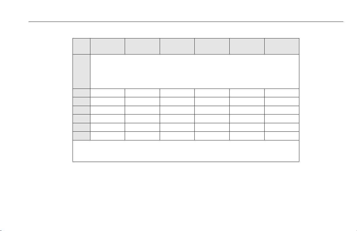
Table 2-1. Inspection and Maintenance Table
TYPE FREQUENCY
Pre-Start
Inspection
Pre-Delivery Inspection
(See Note Below)
Frequent
Inspection
Annual Machine
Inspection
Preventative
Maintenance
NOTE: Inspection forms are available from JLG. Use the Service and Maintenance Manual to perform inspections.
Before using each day; or whenever there’s an Operator
change.
Before each sale, lease, or rental delivery. Owner, Dealer, or User Qualified JLG Mechanic Service and Maintenance Manual
In service for 3 months or 150 hours, whichever comes
first; or Out of service for a period of more than 3
months; or Purchased used.
Annually, no later than 13 months from the date of prior
inspection.
At intervals as specified in the Service and Maintenance
Manual.
PRIMARY
RESPONSIBILITY
User or Operator User or Operator Operator and Safety Manual
Owner, Dealer, or User Qualified JLG Mechanic Service and Maintenance Manual
Owner, Dealer, or User Factory-Trained
Owner, Dealer, or User Qualified JLG Mechanic Service and Maintenance Manual
SERVICE
QUALIFICATION
Service Technician
(Recommended)
and applicable JLG inspection
form
and applicable JLG inspection
form
Service and Maintenance Manual
and applicable JLG inspection
form
REFERENCE
3121211 – JLG Lift – 2-3

SECTION 2 - USER RESPONSIBILITIES, MACHINE PREPARATION, AND INSPECTION
2.3 PRE-START INSPECTION
The Pre-Start Inspection should include each of the following:
1. Cleanliness – Check all surfaces for leakage (oil, fuel,
or battery fluid) or foreign objects. Report any leakage
to the proper maintenance personnel.
2. Decals and Placards – Check all for cleanliness and
legibility. Make sure none of the decals and placards
are missing. Make sure all illegible decals and placards
are cleaned or replaced.
3. Operators and Safety Manuals – Make sure a copy of
the Operator and Safety Manual, AEM Safety Manual
(ANSI Markets Only), and ANSI Manual of Responsibilities (ANSI Markets Only) is enclosed in the weather
resistant storage container.
4. Walk-Around Inspection – Refer to Figure 2-1. on
page 2-7.
5. Battery – Charge as required.
6. Fuel – (Combustion Engine Powered Machines Only) –
Add proper fuel as necessary.
7. Hydraulic Oil – Check hydraulic oil level. Add hydraulic oil as required.
8. Function Check – Once “Walk-Around” Inspection is
complete, perform a function check of all systems in
an area free of overhead and ground level obstructions. Refer to Section 3 for specific instructions.
IF MACHINE DOES NOT OPERATE PROPERLY, TURN OFF MACHINE IMMEDIATELY! REPORT PROBLEM TO PROPER MAINTENANCE PERSONNEL. DO NOT
OPERATE MACHINE UNTIL IT IS DECLARED SAFE FOR OPERATION.
2-4 – JLG Lift – 3121211

SECTION 2 - USER RESPONSIBILITIES, MACHINE PREPARATION, AND INSPECTION
CAUTION
NOTICE
2.4 FUNCTION CHECK
The function check of all systems should be performed in an
area free of overhead and ground level obstructions. Perform a
function check as follows:
1. Set-up machine for operation according to instructions in Section 3. Install outriggers, level machine,
make sure all wheels are off the ground, etc.
2. Enter platform, raise and lower platform 2 ft to 3 ft
(.61m to .92 m) several times. Check for smooth elevation and lowering of platform.
3. With platform completely lowered, check hydraulic oil
level in reservoir at ground control station. Maintain
an oil level to "Fill to Line" indicator on side of reservoir. NEVER USE HYDRAULIC BRAKE FLUID.
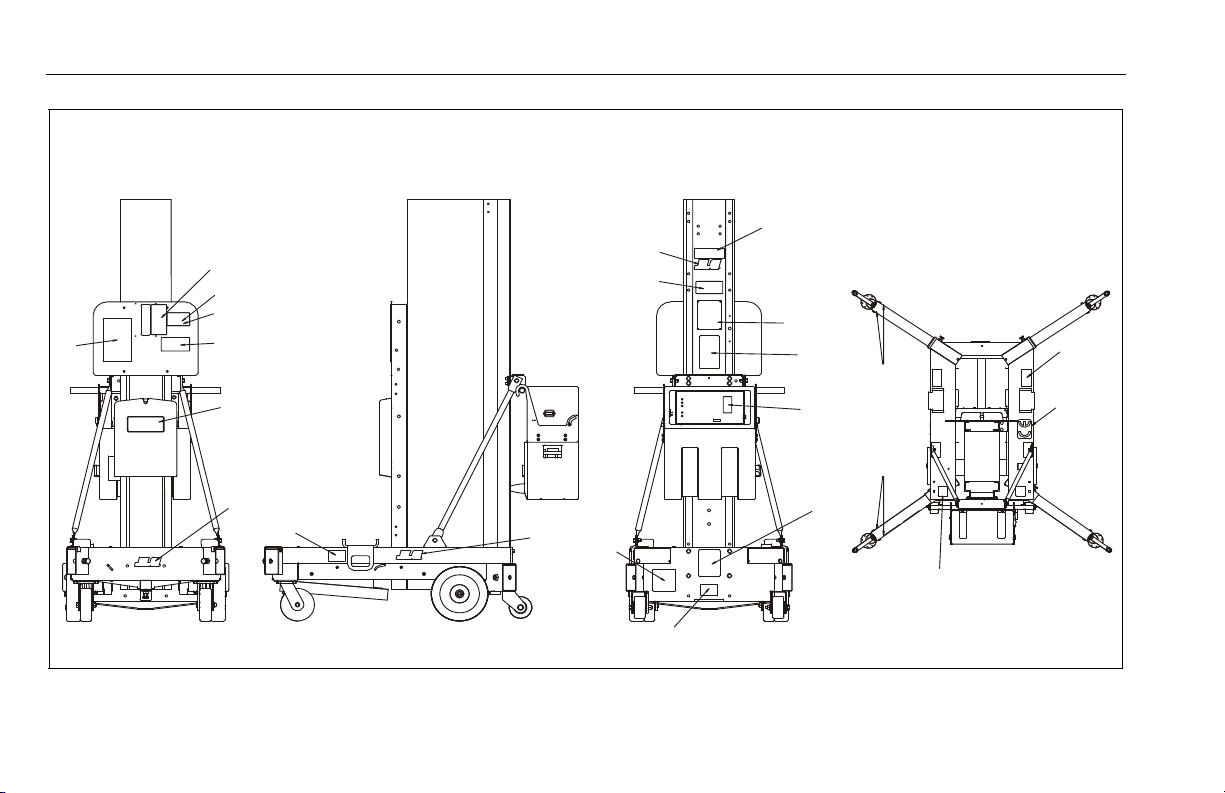
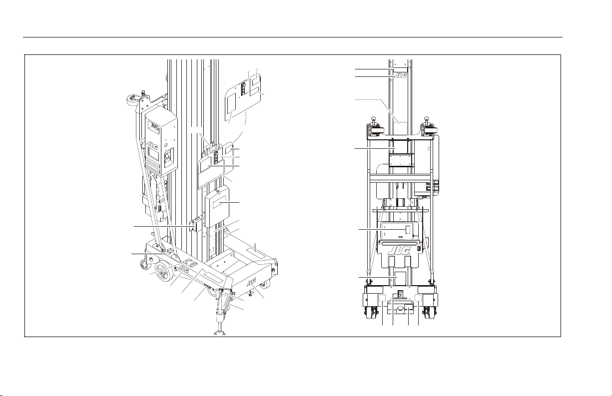
2.5 DAILY WALK-AROUND INSPECTION
General
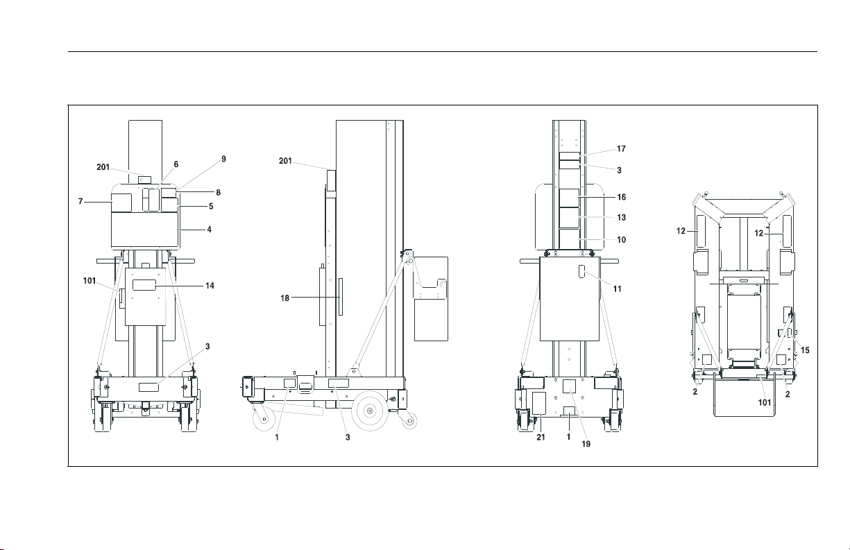
Begin Walk-Around Inspection at item 1 (See Figure 2-1. on
page 2-7). Continue around machine checking each item in this
check list.
TO AVOID POSSIBLE INJURY, BE SURE MACHINE POWER IS OFF DURING
WALK-AROUND INSPECTION.
DO NOT OVERLOOK VISUAL INSPECTION OF CHASSIS UNDERSIDE. CHECKING
THIS AREA MAY RESULT IN DISCOVERY OF CONDITIONS WHICH COULD CAUSE
EXTENSIVE MACHINE DAMAGE.
NOTE: On each item, make sure there are no loose or missing
parts. That they are securely fastened and that no visible
damage exists in addition to any other criteria mentioned.
1. Front Caster Wheels - Properly secured, wheels and
casters turn freely. Brakes lock and release - prevent
wheels from rolling when locked.
2. Rear Wheels - Properly secured. Wheels turn freely.
3. Tiltback Wheels - Properly secured. Wheels turn
freely.
3121211 – JLG Lift – 2-5

SECTION 2 - USER RESPONSIBILITIES, MACHINE PREPARATION, AND INSPECTION
4. Base Frame - Components properly secured, no loose
wires dangling below base; bubble level in place and
functioning properly.
5. Tilt Back Assembly - (36AM/41AM Models Only) Prop-
erly secured; no parts missing i.e.. safety pins, gas
spring cylinder(s), caster wheels, etc.
6. Battery/Charger Box Assembly - (DC Voltage
Machines) Proper battery electrolyte level, no cable
corrosion. Battery box pivots freely when machine is
tilted for transporting (36AM/41AM Models Only).
7. Outrigger Interlock Indicator LED’s - See note
above.
8. Outrigger Sockets - Outrigger lock/release pins in
place and secure, no visible damage. Outrigger interlock contacts (inside outrigger sockets) secure and
clean.
9. Outrigger Beams - Outrigger interlock contacts properly installed and clean (on bottom of outrigger
assembly). Leveling jacks secure to the outrigger
assembly, lubricated and functioning properly.
10. Motor/Pump/Reservoir Power Unit - No evidence of
hydraulic leaks. Check that hydraulic reservoir fluid
level is filled to the "Fill to Line" mark on the side of the
reservoir.
11. Manual Release Control Valve - See note above.
12. Ground Controls - Key switch operable, placards
secure and legible; emergency stop switch, properly
set for operation.
13. Mast Assembly - Inspect mast chains or cables as per
note above.
14. Platform Rail Installation - Entry gate/bar in proper
working order.
15. Platform Assembly - Secure to mast; Control and
power cables properly tensioned and seated in control
cable sheaves; control cable sheaves rotate freely.
16. Platform Controls - Placards secure and legible,
emergency shut-off button set for operation. Operators manual enclosed in manual storage tube.
2-6 – JLG Lift – 3121211
SECTION 2 - USER RESPONSIBILITIES, MACHINE PREPARATION, AND INSPECTION
1
2
3
5
8
4
6
7
9
11
10
12
13
16
15
14
1. Caster Wheels and Brakes
2. Rear Wheel
3. Tilt Back Wheel
4. Base Frame
5. Tilt-Back Assembly (Not Shown - 36/41AM only)
6. Battery/Charger Box Assembly
7. Outrigger Interlock Indicator LED’s
8. Outrigger Sockets
9. Outrigger Beams
10. Motor/Pump/Reservoir Power Unit
11. Manual Release Control Valve
12. Ground Controls
13. Mast Assembly
14. Platform Rail Installation
15. Platform Assembly
16. Platform Controls
3121211 – JLG Lift – 2-7
Figure 2-1. Daily Walk-Around inspection

SECTION 2 - USER RESPONSIBILITIES, MACHINE PREPARATION, AND INSPECTION
NOTES:
2-8 – JLG Lift – 3121211

SECTION 3 - MACHINE CONTROLS AND INDICATORS
NOTICE
SECTION 3. MACHINE CONTROLS AND INDICATORS
3.1 GENERAL
3.2 CONTROLS AND INDICATORS
Ground Control Station
THE MANUFACTURER HAS NO DIRECT CONTROL OVER MACHINE APPLICATION AND OPERATION. THE USER AND OPERATOR ARE RESPONSIBLE FOR
CONFORMING WITH GOOD SAFETY PRACTICES.
This section provides the necessary information needed to
understand control functions.
3121211 – JLG Lift – 3-1
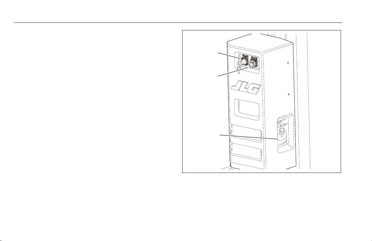
(See Figure 3-1.)
NOTE: For overnight parking or battery charging, be sure the
POWER ON/OFF KEY SWITCH is positioned to OFF to prevent battery drain.
1. POWER ON/OFF Key Switch
A key switch located on the ground control station controls
power to all functions on the machine.
2. POWER/EMERGENCY STOP
The two position switch allows power to the platform and
ground controls when RESET (ON). When pushed in (OFF),
power is shut off to the platform and ground controls.
3. HYDRAULIC RESERVOIR / CIRCUIT BREAKER / FUSE
(located inside the ground control station housing)
The hydraulic oil level can be checked through an access
hole in the side of the cover.
NOTE: Check hydraulic oil only when platform is completely low-
ered and after cycling platform up/down a few times.
SECTION 3 - MACHINE CONTROLS AND INDICATORS
2
1
3
A 20 amp reset type circuit breaker is located on the cover of
the electrical box on AM-AC Models.
On AM-DC Models, a 5 Amp fuse is located inside the ground
control station cover.
Figure 3-1. Ground Control Station.
1. Power ON/OFF Key
2. Power/Emergency Stop
3. Hydraulic Reservoir/Circuit Breaker/Fuse
3-2 – JLG Lift – 3121211

Manual Descent Valve
1
2
3
(See Figure 3-2. or Figure 3-3.)
Located at the rear and bottom of the base frame. This pull to
release - spring loaded return valve (RED Knob), allows for
lowering of th e platform in an emergenc y or powe r failure.
Platform Control Station
(See Figure 3-4.)
1. POWER/EMERGENCY STOP
A two position mushroomed shaped switch furnishes power
to the platform and ground controls when RESET (ON).
When pushed in (OFF), power is shut off to the platform and
ground controls.
2. PLATFORM UP Button.
When depressed simultaneously with ENABLE button raises
the platform.
3. FUNCTION ENABLE Button.
This (GREEN) button must be depressed for machine to
operate.
SECTION 3 - MACHINE CONTROLS AND INDICATORS
Figure 3-2. Manual Descent Valve Location.
1. Manual Descent Valve
2. Tie-Down Lugs
3. Mast
4. PLATFORM DOWN Button.
When depressed simultaneously with ENABLE button lowers
the platform.
3121211 – JLG Lift – 3-3

SECTION 3 - MACHINE CONTROLS AND INDICATORS
1
2
3
1
2
3
4
Figure 3-3. Manual Descent Valve Location.
1. Manual Descent Valve
2. Tie-Down Lugs
3. Mast
3-4 – JLG Lift – 3121211
Figure 3-4. Platform Control Station.
1. Emergency Stop (RED)
2. Platform UP (WHITE)
3. Function Enable (GREEN)
4. Platform DOWN (WHITE)
3.3 DECAL INSTALLATIONS
SECTION 3 - MACHINE CONTROLS AND INDICATORS
Figure 3-5. Decal Installation. (ANSI/CSA) (Machines prior to S/N-0900031618)
3121211 – JLG Lift – 3-5

SECTION 3 - MACHINE CONTROLS AND INDICATORS
Table 3-1. Decal Installation Chart (ANSI and CSA) (See Figure 3-5.)
Item ANSI
ANSI
(LAT)
ANSI
(BRZ)
ANSI
(JPN)
ANSI
(CHI)
CSA
(FRE)
1 1702300 1702300 1702300 1702300 1702300 1703814
2 1703073 1703073 1703073 1703073 1703073 1703817
3 — 1703681 — 1703681 1703681 —
4 1703778 1704027 1704019 1704084 1704075 1703778
5 1703779 — — — — —
6 1703780 1704028 1704020 1704085 1704076 1703780
7 1703781 1704029 1704021 1704086 1704077 1703781
8
9
1706346
1706344
(1)
(2)
1707100
1707101
(1)
(2)
1707102
1707103
(1)
(2)
1707104
1707105
(1)
(2)
1707106
1707107
(1)
(2)
1706344
1706366
(1)
(2)
10 1703784 1704030 1704022 1704088 1704078 1703784
11 1703785 1704031 1704023 1704089 1704079 1703785
12 1703786 1704032 1704024 1704090 1704081 1703786
13
1703787
(3)
1704033
(3)
1704025
(3)
1704091
(3)
1704082
(3)
1703787
(3)
14 1703788 1703788 1703788 1703788 1703788 1703788
15 1703789 1704034 1704026 1704092 1704083 1703789
16 1707081 1707080 1707080 1707080 1707080 1707081
3-6 – JLG Lift – 3121211
SECTION 3 - MACHINE CONTROLS AND INDICATORS
Table 3-1. Decal Installation Chart (ANSI and CSA) (See Figure 3-5.)
Item ANSI
17
18 1703815 — 1703828 1704151 — 1703815
19 ——————
20 ——————
21 1700584 1700584 1700584 1700584 1700584 1700584
101 3251243 3251243 3251243 3251243 3251243 3251243
201 1703994 1703994 1703994 1703994 1703994 1703994
NOTE: (1) - 30AM/36AM/41AM Only
(2) - 20AM/25AM Only
(3) - Installed on 36AM or 41AM machines with tiltback option only.
ANSI
(LAT)
ANSI
(BRZ)
1703902 - 20AM
1703903 - 25AM
1703904 - 30AM
1703905 - 36AM
1703906 - 41AM
ANSI
(JPN)
ANSI
(CHI )
CSA
(FRE)
3121211 – JLG Lift – 3-7
SECTION 3 - MACHINE CONTROLS AND INDICATORS
5
4
3
6
11
2
16
13
16
16
10
9
7
18
18
12
14
13
17
15
8
19
20
Figure 3-6. Decal Installation (CE) (Machines prior to S/N-0900031618)
3-8 – JLG Lift – 3121211
SECTION 3 - MACHINE CONTROLS AND INDICATORS
Table 3-2. Decal Installation Chart (CE Specification) (See Figure 3-6.)
Item
CE
(ENG/(AUS)CE(DUT)
CE
(FRE)
CE
(GER)
CE
(ITA)
CE
(SPA)
1 1001098588 - Decal Kit *
2 1701509 *
3 1704094 * (1)
4 1704095 * (2)
5 1705801 *
6 1705802 *
7 1705803 *
8 1705805 *
9 1705831 *
10 1001098578 * (3)
11 1001098579 *
12 1700584
13 1702300
14 1702631
15 1702928
16 1703681
17 1703817
3121211 – JLG Lift – 3-9
SECTION 3 - MACHINE CONTROLS AND INDICATORS
Table 3-2. Decal Installation Chart (CE Specification) (See Figure 3-6.)
Item
18 4420051
19
20 3252606
NOTE: (1) - 30/36/41AM
CE
(ENG/(AUS)CE(DUT)
(2) - 20/25AM
(3) - Installed on 36AM or 41AM machines with tiltback option only.
CE
(FRE)
1703902 - 20AM
1703903 - 25AM
1703904 - 30AM
1703905 - 36AM
1703906 - 41AM
CE
(GER)
CE
(ITA)
CE
(SPA)
3-10 – JLG Lift – 3121211

15
20
148
21
164
12
2
20
148
12
14
4
7
163
6
8
135
1
3
118
20
148
13
117
10
154
11
16
16
219
SECTION 3 - MACHINE CONTROLS AND INDICATORS
Figure 3-7. Decal Installation. (ANSI/CSA) (Machines S/N-0900031618 to Present)
3121211 – JLG Lift – 3-11

SECTION 3 - MACHINE CONTROLS AND INDICATORS
Table 3-3. Decal Installation Chart (ANSI and CSA) (See Figure 3-7.)
Item ANSI
ANSI
(LAT)
ANSI
(BRZ)
ANSI
(JPN)
ANSI
(CHI - SIMP)
ANSI
(CHI - TRAD)
CSA
(FRE)
1 1700584
2 1702300
3 Bar Code - Not Available
4 1703778 1704027 1704019 1704084 1704075 1706692 1703778
5 1703779 — — — — — —
6 1703780 1704028 1704020 1704085 1704076 1706693 1703780
7 1703781 1704029 1704021 1704086 1704077 1706694 1703781
(1)
8
(2)
8
1706346 1707101 1707103 1707105
1706344 1707100 1707102 1707104
1707107
1707106
1706366
1706344
9 Not Used
10 1703784 1704030 1704022 1704088 1704078 1706696 1703784
11 1703785 1704031 1704023 1704089 1704079 1706697 1703785
12 1703786 1704032 1704024 1704090 1704081 1703786
13
(3)
1703787 1704033 1704025 1704091 1704082 1706695 1703787
14 1701509
15 1703789 1704034 1704026 1704092 1704083 1706699 1703789
16 1703817
17 Not Used
3-12 – JLG Lift – 3121211
SECTION 3 - MACHINE CONTROLS AND INDICATORS
Table 3-3. Decal Installation Chart (ANSI and CSA) (See Figure 3-7.)
Item ANSI
18 Not Used
19 1001115864
20 1703681
21 Not Used 1703464
101 to 115 Not Used
116 Serial Number Plate - Not Available
117 Not Used 1706351
118 Model Designation - 20AM-1703902 / 25AM-1703903 / 30AM-1703904 / 36AM-1703905 / 41AM-1703906
119 to 134 Not Used
135 1703994
136 to 147 Not Used
148 1703681 - JLG Logo
149 to 153 Not Used
154 1001110242 - JLG Service
155 to 162 Not Used
163 Max. Outrigger Load Options: 20AM-1706445 / 25AM-1706446 / 30AM-1706447 / 36AM-1706448 / 41AM-1706449
164 Voltage Options: 3252761-120V AC / 3252760-220V-240V AC
NOTE: (1) - 20AM/25AM Only
(2) - 30AM/36AM/41AM Only
(3) - Installed on 36AM or 41AM machines with tiltback option only.
ANSI
(LAT)
ANSI
(BRZ)
ANSI
(JPN)
ANSI
(CHI - SIMP)
ANSI
(CHI - TRAD)
CSA
(FRE)
3121211 – JLG Lift – 3-13
SECTION 3 - MACHINE CONTROLS AND INDICATORS
118
15
10
9
4
3
8
6
116
161612
19
51
14
15
15
52
164
7
7
12
53
17
1
10
5
4
3
11
13
135
OR
CE SPEC.
AUSTRALIAN
SP EC.
5
3-14 – JLG Lift – 3121211
Figure 3-8. Decal Installation (CE) (Machines S/N-0900031618 to Present)

SECTION 3 - MACHINE CONTROLS AND INDICATORS
Table 3-4. Decal Installation Chart (CE Specification) (See Figure 3-8.)
Item
CE
(ENG)
CE
(DUT)
CE
(FRE)
CE
(GER )
CE
(ITA)
CE
(SPA)
CE
(AUS)
1 1701509
2 Not Used
3
1704094
(1)
/ 1704095
(2)
4 1705801 1703780
5 1702802 1703781
6 1705803 1703785
7 1705805 1703786
8 1705831 1703784
9 1001098578 1703787
10 1001098579 1703778
11 1700584
12 1702300
13 Not Available - BarCode
14 1702928 —
15 1703681
16 1703817
17 4410051 —
3121211 – JLG Lift – 3-15

SECTION 3 - MACHINE CONTROLS AND INDICATORS
Table 3-4. Decal Installation Chart (CE Specification) (See Figure 3-8.)
Item
18 Not Used
19 1001115864
20 to 50 Not Used
51 Not Used 1703789
52 Not Used 1703464
53 Not Used 1705796
101 to 115 Not Used
116 Serial Number Plate - Not Available
117 Not Used
118
119 to 134 Not Used
135 1703994 (Optional)
136 to 163 Not Used
164 120V - AC - 3255761 / 220V-240V AC - 3255760
NOTE: (1) - 30/36/41AM
CE
(ENG)
20AM-1703902 / 25AM-1703903 / 30AM-1703904 / 36AM-1703905 / 41AM-1703906
(2) - 20/25AM
(3) - Installed on 36AM or 41AM machines with tiltback option only.
CE
(DUT)
CE
(FRE)
Model Designation Options:
CE
(GER)
CE
(ITA)
CE
(SPA)
CE
(AUS)
3-16 – JLG Lift – 3121211

SECTION 4. MACHINE OPERATION
SECTION 4 - MACHINE OPERATION
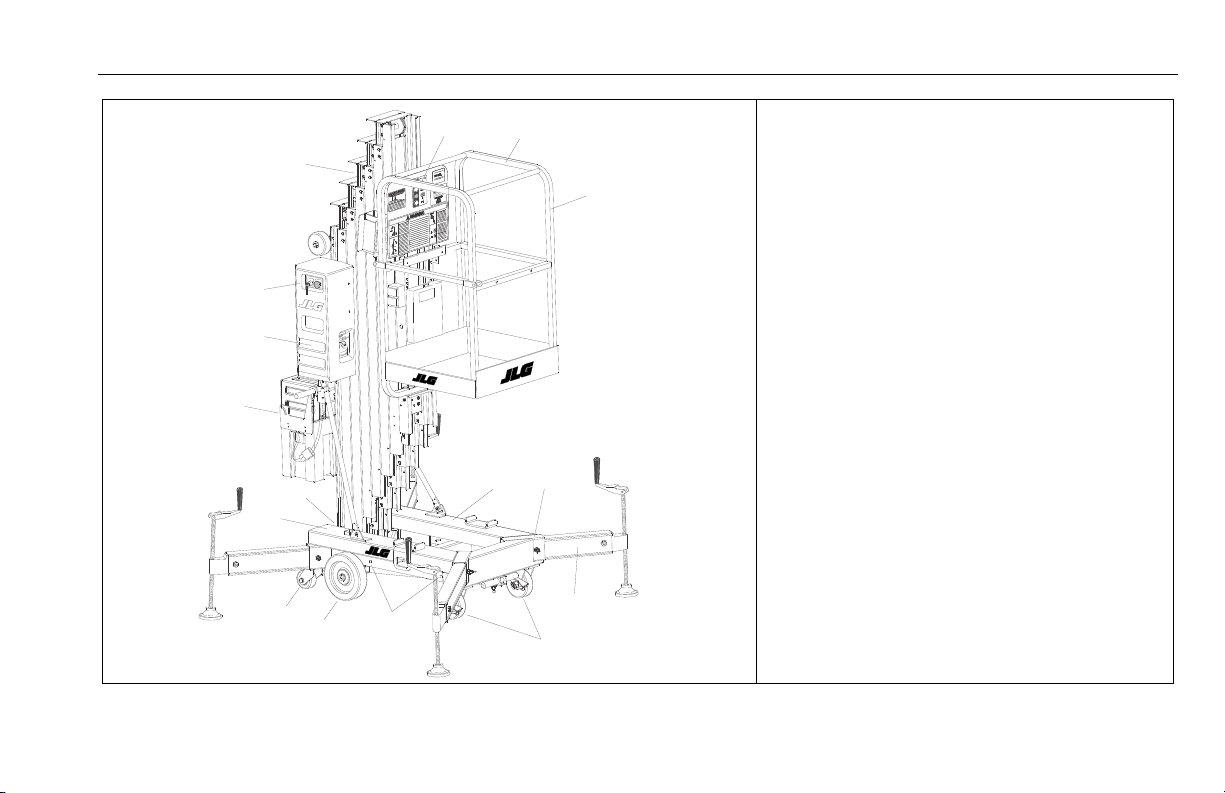
4.1 DESCRIPTION
This machine is a manually propelled machine, with a work platform mounted to an elevating aluminum mast mechanism. The
personnel lift’s intended purpose is to provide personnel (with
their tools and supplies) access to areas above ground level.
The primary operator control station is in the platform. From
this control station, the operator can raise and lower the platform. A ground control station is provided to lower the platform
to the ground in an emergency if the operator in the platform is
unable to do so, or if a power failure should occur.
Vibrations emitted by these machines are not hazardous to an
operator in the work platform. The equivalent continuous AWeighted sound pressure level at the work platform is less than
70dB(A).
3121211 – JLG Lift – 4-1
4.2 OPERATING CHARACTERISTICS AND LIMITATIONS
Capacities
The platform can be raised above the stowed position if:
• The machine is positioned on a smooth, firm surface on
which the machine is capable of being leveled.
• Load is within manufacturer’s rated capacity.
• All machine systems are functioning properly.
• The machine is leveled and outriggers are properly installed
as indicated by the outrigger interlock LED lights on the
base frame.
SECTION 4 - MACHINE OPERATION
NOTICE
1/8 "
(3 mm)
1
3
2
4
4.3 BATTERY CHARGING & MAINTENANCE - (DC MODELS ONLY)
AM-DC Models are equipped with a 12 volt, 10 amp output dual voltage (120/240V) input battery charger. The charger is
microprocessor controlled featuring an automatic charge sensing circuit which can determine cell voltage and regulate charger output and terminate charging as required.
MACHINES BUILT STARTING WITH S/N-0900031618 AND LATER WERE
EQUIPPED WITH A NEW COMPACT DESIGN HOUSING FOR THE CHARGER AND
BATTERY. THE CHARGER AND BATTERY OPERATION ARE UNCHANGED.
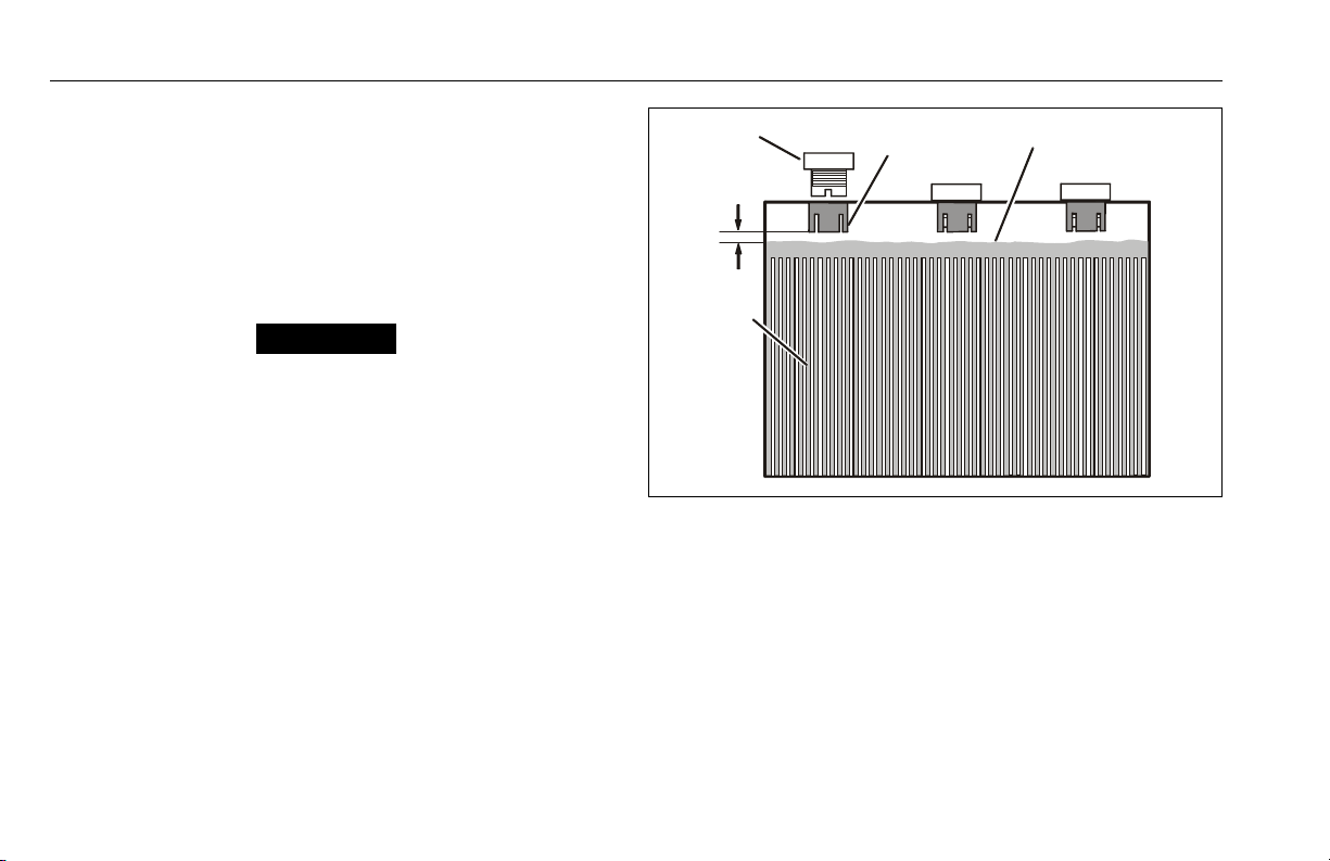
Battery Maintenance and Safety
BATTERY ACID IS HIGHLY CORROSIVE. AVOID CONTACT WITH SKIN AND CLOTHING AT
ALL TIMES.
BATTERY ACID RELEASES AN EXPLOSIVE GAS WHILE CHARGING, ALLOW NO OPEN
FLAMES, SPARKS OR LIGHTED TOBACCO PRODUCTS IN THE AREA WHILE CHARGING
BATTERIES. CHARGE BATTERIES ONLY IN A WELL VENTILATED AREA.
ADD ONLY DISTILLED WATER TO BATTERIES. WHEN ADDING DISTILLED WATER TO THE
BATTERIES, A NON-METALLIC CONTAINER AND/OR FUNNEL MUST BE USED.
The battery fluid level should be approximately 1/8" (3mm)
below vent tubes. (See Figure 4-1.)
Figure 4-1. Battery Fluid Level.
1. Battery Filler Cap
2. Vent Tub e
3. Fluid Level
4. Cell Plates
4-2 – JLG Lift – 3121211
SECTION 4 - MACHINE OPERATION
NOTICE
2
1
4
3
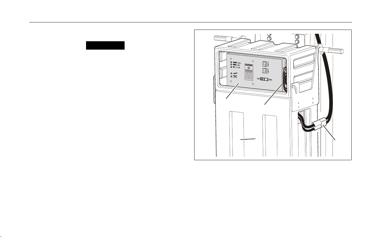
Battery Charger Operation
ALWAYS CHECK THE VOLTAGE SELECT SWITCH ON THE FACE OF THE BATTERY
CHARGER BEFORE OPERATION. IF NOT SET TO THE PROPER AC POWER INPUT
VOLTAGE, THE CHARGER MAY BE DAMAGED.
1. Turn the ground control key switch to the OFF position.
2. Set the AC voltage switch on the face of the charger
for the local AC line voltage.
3. Plug the battery charger AC power cable, stowed
inside the battery/charger carrier (beside charger) into
a properly grounded receptacle. Use a suitable extension cord, if necessary.
4. The charger runs through a self-diagnostic check. The
LED’s on the face of the charger flash in the following
sequence;
a. First all five (5) LED’s flash three (3) times.
b. Next each LED lights in sequence.
c. Finally all five (5) LED’s flash three (3) times again.
5. When ready to charge, the CHARGER ON LED and the
INCOMPLETE CHARGE (25%) LED on the front panel of
the charger will light up, the charger will then begin to
charge the batteries.
Figure 4-2. Battery Box and Charger Assembly.
(D.C. Model Only)
1. Battery Box/Charger Assembly
2. DC Battery Charger
3. Charger AC Power Cord
4. DC - Battery to Machine Main
Power Connec tor
3121211 – JLG Lift – 4-3

SECTION 4 - MACHINE OPERATION
1
2
3
4
5
6. When the battery cell voltage reaches 2.37 V/cell the
80% CHARGE LED will light up. The charger then continues to monitor the increase in charge until it sees
no increase, and then terminates the charging process.
7. The CHARGE COMPLETE (100%) LED will light when
the batteries are fully charged.
8. Unplug the charger AC power cord and stow the cord.
Abnormal Cycle Indicator LED
The ABNORMAL CYCLE indicator LED will light when;
• The AC input to the charger was interrupted.
• There is a dead cell or cells in the battery.
• One or more of the battery connectors are loose or cor-
roded.
Figure 4-3. Dual Voltage Charger - Front Panel.
1. % of Charge in Progress
LED’s (Green)
2. Charger On LED (Green)
3. Abnormal Cycle LED
(Yellow)
4. Circuit AC Circuit Breakers
5. AC Voltage Selection
Switch
4-4 – JLG Lift – 3121211
SECTION 4 - MACHINE OPERATION
4.4 MACHINE SET-UP AND OPERATION
To set-up machine for operation the operator must:
1. Position machine in work area.
NOTE: If AC powered machine, connect machine to a grounded
AC receptacle with a heavy duty extension cord equipped
with an equipment grounding conductor.
If DC powered machine, check battery box assembly is
installed, battery is charged and connected to machine’s
DC receptacle.
2. Set key switch to ON position at ground control station.
3. Check both emergency stop switches are in RESET
position for operation.
4. Check manual decent control valve (red knob) is
closed.
APPLY FRONT CASTER BRAKES SO MACHINE DOES NOT ROLL IN ANY DIRECTION. DO NOT INSTALL OUTRIGGERS OR ELEVATE PLATFORM UNTIL FRONT
CASTER BRAKES ARE LOCKED.
5. Apply caster brakes.
6. Install outriggers.
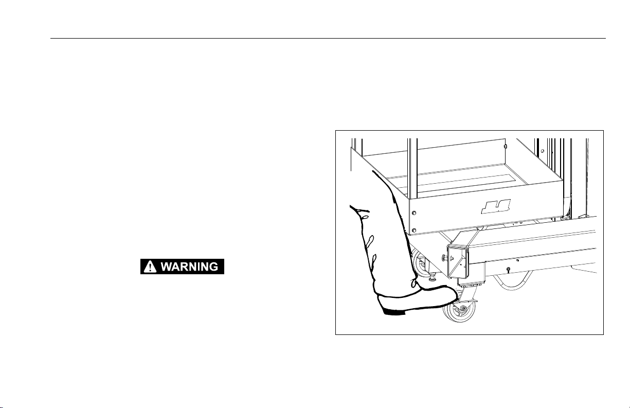
Caster Brake Operation
1. Press down on caster brake lever on both casters at
front of machine to apply caster brakes.
2. To disengage caster brake, apply pressure or lift up on
caster brake lever.
Figure 4-4. Setting & Releasing Caster Brake
3121211 – JLG Lift – 4-5

SECTION 4 - MACHINE OPERATION
NOTICE
NOTICE
Outrigger Installation
(See Figure 4-5. on page 4-7)
AS A SAFETY PRECAUTION, DUE TO DIFFERENT LENGTHS, OUTRIGGER BEAMS
ARE DESIGNED TO FIT A SPECIFIC MODEL AND ARE NOT INTERCHANGEABLE.
1. Remove one outrigger beam from the stowage socket.
2. Insert outrigger beam into an outrigger socket on the
base frame with outrigger interlock contact on the
bottom. Push outrigger beam in socket until locking
pin on side of outrigger socket snaps into the outrigger beam detent. Repeat for remaining outriggers.
3. With all outriggers inserted, turn each outrigger jack
down, lifting entire machine until all wheels are off the
ground.
4. When all four (4) wheels are off the ground, use the
bubble level on the base frame to level machine.
MACHINE WILL OPERATE ONLY IF ALL FOUR (4) INTERLOCK LED LIGHTS ARE
ILLUMINATED.
4-6 – JLG Lift – 3121211
SECTION 4 - MACHINE OPERATION
3
2
4
1
5
Figure 4-5. Outrigger Installation.
1. Bubble Level Indicator
2. Outrigger Lock/Release Pin
3. Interlock LED’s
4. Outrigger Beam Assembly
5. Leveling Jack
3121211 – JLG Lift – 4-7

SECTION 4 - MACHINE OPERATION
Platform Loading
platform maximum rated load capacity is shown on a placard
located on the platform control panel. Applies to all available
AM model platforms.
Maximum capacity for each model is as follows:
Table 4-1. Maximum Platform Capacity.
PLATFORM CAPACITY
MODEL
20AM -
DC/AC
25AM -
DC/AC
30AM -
DC/AC
36AM -
DC/AC
41AM -
DC/AC
FOR MACHINES BUILT TO SPECIFICATION
ANSI & C.S.A. -
B354.1-04
350 lb.
(160 kg)
350 lb.
(160 kg)
350 lb.
(160 kg)
300 lb.
(135 kg)
300 lb.
(135 kg)
CE
350 lb.
(160 kg)
350 lb.
(160 kg)
300 lb.
(135 kg)
300 lb.
(135 kg)
300 lb.
(135 kg)
C.S.A. -
B354.1-M82
300 lb.
(135 kg)
300 lb.
(135 kg)
300 lb.
(135 kg)
250 lb.
(113 kg)
250 lb.
(113 kg)
Platform Operation
1. Enter platform and close gate/slide bar.
2. To raise platform, press FUNCTION ENABLE button and
platform UP button simultaneously. Upon reaching
desired elevation level, release UP and FUNCTION
ENABLE buttons.
CHECK AREA BENEATH PLATFORM IS FREE OF PERSONNEL AND OBSTRUCTIONS PRIOR TO LOWERING PLATFORM.
3. To lower platform, press FUNCTION ENABLE button
and platform DOWN button on control panel simultaneously.
4-8 – JLG Lift – 3121211

4.5 QUICK-CHANGE PLATFORM MOUNTS
1
2
3
4
(See Figure 4-6.)
The AM model is equipped with platform mounting for quick
and simple exchange of platforms.
Platform Removal
1. Remove both pins holding lower platform support rail
to platform lower mount.
2. Remove both pins holding upper platform support rail
to platform upper mount.
3. Using suitable lifting equipment or another person,
swing lower platform support rail forward, away from
mast to clear platform lower mount, then lift upper
platform support rail up and out of platform upper
mount.
SECTION 4 - MACHINE OPERATION
Figure 4-6. Quick Change Platform Mount.
1. Platform Upper Mount
2. Upper Mount Attach Pins
3. Platform Lower Mount
4. Lower Mount Attach Pins
3121211 – JLG Lift – 4-9

SECTION 4 - MACHINE OPERATION
Platform Installation
1. Using two people or suitable lifting equipment, lift
platform and set platform upper support rail into the
upper platform mount on the mast.
2. Swing platform lower support rail into lower platform
mount on the mast.
3. Secure platform support rails with two (2) platform
upper mount pins, and two (2) lower platform mount
pins.
4.6 MACHINE SHUT DOWN AND PARK
1. Ensure platform is fully lowered, turn key switch to
OFF position.
2. Store outrigger beams in stowage sockets.
3. Move machine to a well-protected and well-ventilated
area. In a hostile environment, cover machine for protection.
4. Apply caster brakes and chock at least two wheels
when parking machine for extended time.
5. Remove key switch to disable machine from unauthorized use.
4-10 – JLG Lift – 3121211

SECTION 4 - MACHINE OPERATION
CAUTION
NOTICE
4.7 TRANSPORT, LIFTING AND TIE DOWN
General
To move machine from work area to work area the operator
may:
• Push machine on its base wheels.
• Push machine in Tilt-Back mode.
(36AM and 41AM only)
• Move machine using a forklift.
• Load machine on back of a pickup truck, using the built-in
load bar.
NOTE: 36AM and 41AM machines are equipped with a perma-
nently attached tilt-back assembly to allow machine to fit
through standard size doorways.
Transporting by Pushing
The standard machine’s base frame is equipped with load bearing wheels mounted on a straight axle at the mast end of the
machine; and a pair of heavy duty swivel caster wheels
mounted on the frame at the platform end of the machine.
REFER TO SECTION 1.2, TRANSPORTING SAFETY PRECAUTIONS BEFORE
TRANSPORTING MACHINE.
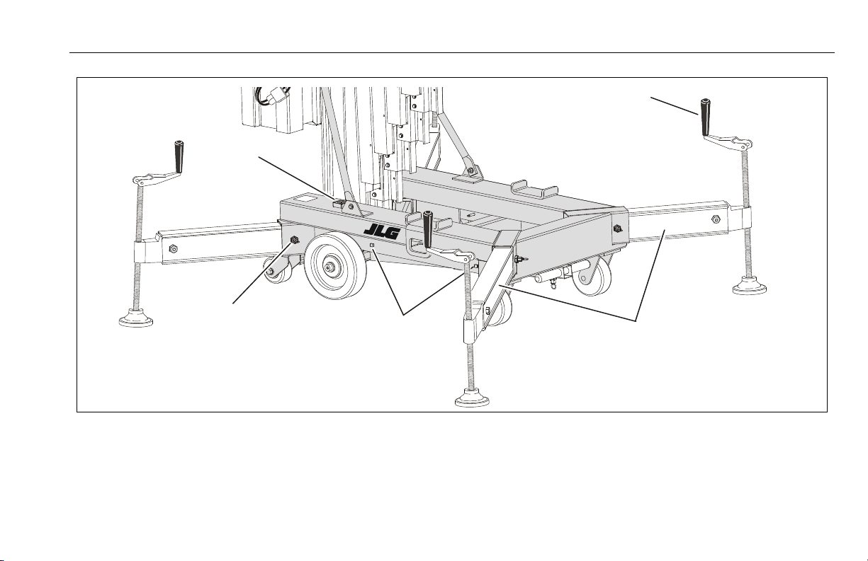
Tilt-Back Assembly Set-up (AM36/AM41) - Machines Prior to S/ N - 0900031618
(See Figure 4-7.)
PLATFORM MUST BE FULLY LOWERED, AND OUTRIGGER BEAMS MUST BE
STOWED. ON DC MODELS ENSURE BATTERY BOX/CHARGER ASSEMBLY IS NOT
OBSTRUCTED AND IS CLEAR TO SWING ONCE MACHINE IS TILTED.
1. Move machine to an area that is level, clear and free of
obstacles.
2. Hold the tilt-back assembly in place and remove the
release pins from the mast support crossbar.
3. Carefully lower the tilt-back assembly as far as it will
go.
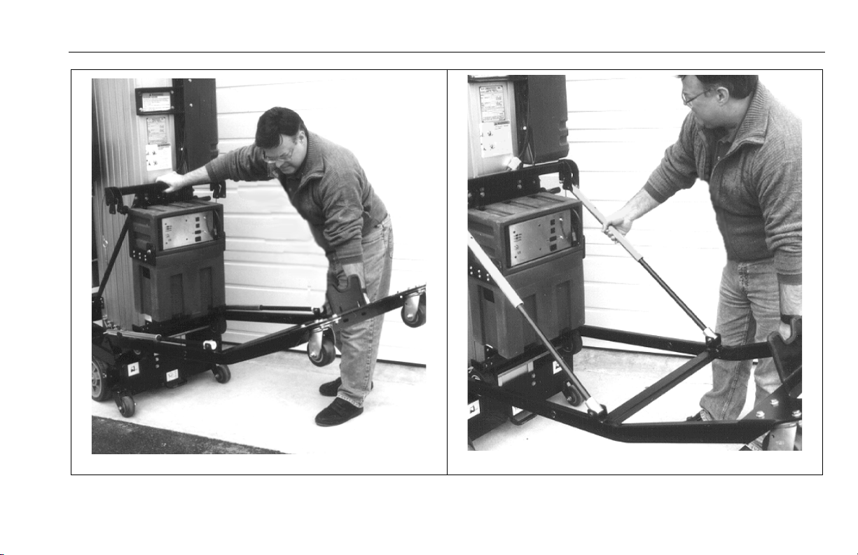
4. Pull either of the gas spring cylinders up out of their
retaining clip. Guide the groove pins on the end of the
cylinder into the slot on the end of the mast crossbar.
Secure both cylinders to the mast support crossbar by
replacing the pins removed in step 2 to lower the tiltback assembly.
5. Extend and lock the T-handle bar located under the
front of the machine. A release/lock pin is located on
the bottom of the bar.
6. With both hands on the grips of the T-handle lifting
bar, carefully tilt the machine back onto the tilt-back
assembly.
3121211 – JLG Lift – 4-11

SECTION 4 - MACHINE OPERATION
1
2
Figure 4-7. Tilt-Back Assembly Set-Up.
4-12 – JLG Lift – 3121211
SECTION 4 - MACHINE OPERATION
3
4
Figure 4-7. Tilt-Back Assembly Set-Up.
3121211 – JLG Lift – 4-13

SECTION 4 - MACHINE OPERATION
5
6
Figure 4-7. Tilt-Back Assembly Set-Up.
4-14 – JLG Lift – 3121211

SECTION 4 - MACHINE OPERATION
NOTICE
CAUTION
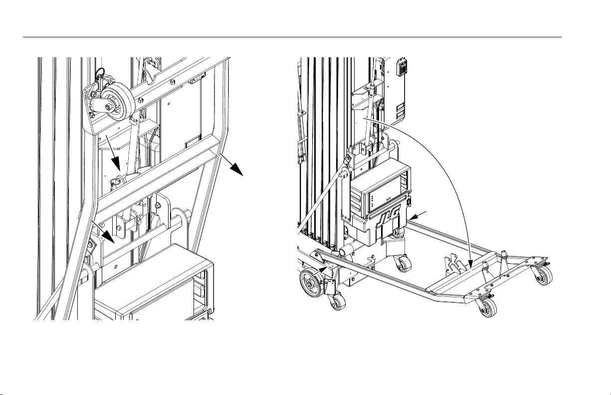
Tilt-Back Assembly Set-up (AM36/AM41) - Machines S/N 0900031618 to Present
(See Figure 4-8., Figure 4-9. and Figure 4-10.)
PLATFORM MUST BE FULLY LOWERED, AND OUTRIGGER BEAMS MUST BE
STOWED. ON DC MODELS ENSURE BATTERY BOX/CHARGER ASSEMBLY IS NOT
OBSTRUCTED AND IS CLEAR TO SWING ONCE MACHINE IS TILTED.
REFER TO SECTION 1.2, TRANSPORTING SAFETY PRECAUTIONS BEFORE
TRANSPORTING MACHINE.
1. Move machine to an area that is level, clear and free of
obstacles.
2. (Step 1) Hold the tilt-back assembly in place and
remove the release pin securing the tilt-back assembly
to the gas spring cylinder.
3. Lower the tilt-back assembly as far as it will go onto it’s
rubber bumpers.
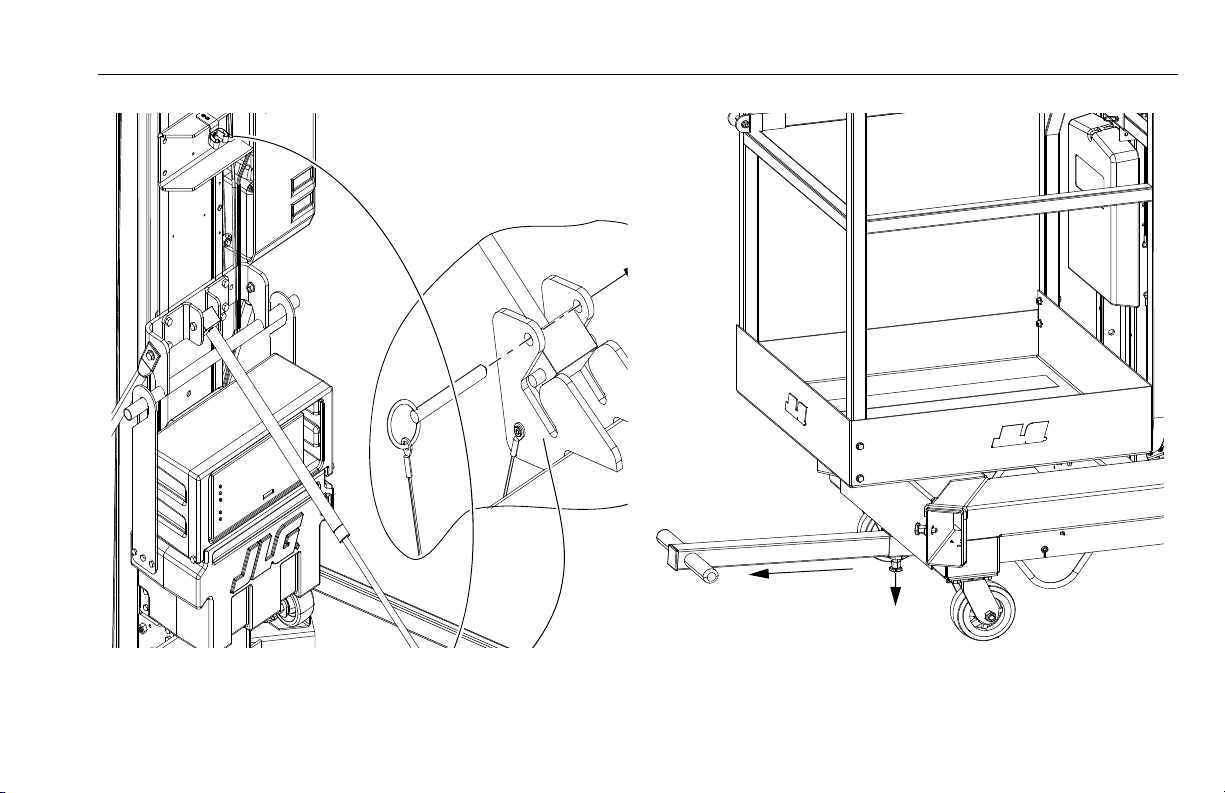
4. (Step 2) Pull the gas spring cylinder out of it’s retaining
clip on the back of the mast assembly. Lower and
extend or retract the cylinder to guide the groove pins
on the end of the cylinder into the slots on the tiltback crossbar assembly bracket. Secure the cylinder to
the tilt-back crossbar bracket by replacing the pin
removed in step 1 to lower the tilt-back assembly.
NOTE: If moving machine in other than a straight line forward,
unlock tilt-back swivel wheels by pulling the swivel wheel
lock pins out then turning pins 90° to the unlock position.
This will allow the tilt-back swivel wheels to rotate freely
and steer machine while moving.
5. (Step 3) Fully extend the T-handle lifting bar located
under the front of the machine by pulling down on
the release/lock pin located under the bar. Fully
extend the lifting bar until the release/lock pin snaps
back in, locking the bar in place. Push or pull bar to be
certain it is secure before lifting machine.
6. (Step 4) With both hands on the grips of the T-handle
lifting bar, carefully lift the front of the machine and
tilt the machine back onto the tilt-back assembly and
the gas spring cylinder.
7. Push machine around using the loop grips just behind
the front swivel wheel assemblies under the base
frame.
3121211 – JLG Lift – 4-15
SECTION 4 - MACHINE OPERATION
Step 1
Figure 4-8. Tilt-Back Assembly Set-Up - Machines S/N - 0900031618 to Present.
4-16 – JLG Lift – 3121211
SECTION 4 - MACHINE OPERATION
Step 2
Step 3
Figure 4-9. Tilt-Back Assembly Set-Up - Machines S/N - 0900031618 to Present.
3121211 – JLG Lift – 4-17

SECTION 4 - MACHINE OPERATION
Step 4
Figure 4-10. Tilt-Back Assembly Set-Up - Machines S/N - 0900031618 to Present.
4-18 – JLG Lift – 3121211

SECTION 4 - MACHINE OPERATION
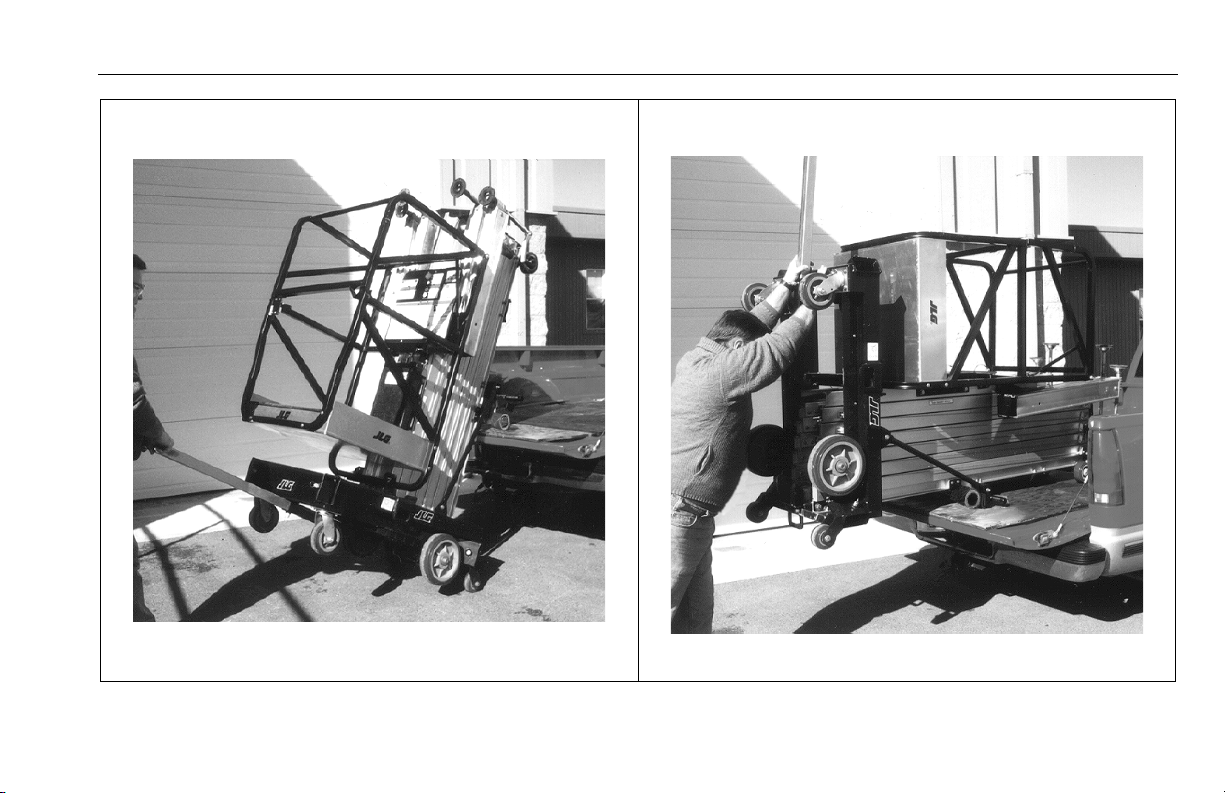
Pickup Truck Loading Device (Option)
(See Figure 4-11.)
NOTE: The stowed mast height of the 36AM and 41AM exceeds
the length of most pick-up truck beds. JLG does not recommend transporting those models by pick-up truck.
AM model machines can be transported in a standard full size
pickup truck. If the machine is equipped with the loading device
option, it can be loaded and unloaded by one person.
NOTE: For a smooth rolling surface and even weight distribution,
it is recommended that 3/4" to 1" (2 to 2.5cm) thick plywood be placed in the truck bed and out onto the tailgate.
This should avoid tailgate damage.
Park truck on a firm, smooth, level surface with the tailgate
open. Remove the battery/charger storage box from DC model
machines.
1. Set load pivot bar on back of mast so bar is set approximately 1 - 2 in (3 to 5 cm) above tailgate height. Use
the spring loaded locking pin to raise or lower the load
pivot bar. Once bar is locked in place, push machine
against the tailgate.
2. At front of the machine, extend the T-handle lifting bar
from the base frame.
3. Begin lifting the machine onto the tailgate of the truck
with the T-handle lifting bar. As machine begins to
pivot be certain the load pivot bar is engaging the
truck tailgate.
4. Continue lifting and pushing machine onto the truck
bed, firmly grasp the machine by the base frame
pushing it all the way into truck bed.
5. Secure machine to the truck bed with rope or tie down
hooks to limit any machine movement while transporting.
To unload machine from truck bed, reverse loading instructions
above.
3121211 – JLG Lift – 4-19

SECTION 4 - MACHINE OPERATION
1
2
Figure 4-11. Loading Machine onto Bed of Pick-Up Truck.
4-20 – JLG Lift – 3121211
SECTION 4 - MACHINE OPERATION
3
4
Figure 4-11. Loading Machine onto Bed of Pick-Up Truck.
3121211 – JLG Lift – 4-21

SECTION 4 - MACHINE OPERATION
5
Figure 4-11. Loading Machine onto Bed of Pick-Up Truck.
4-22 – JLG Lift – 3121211

SECTION 4 - MACHINE OPERATION
Lifting
To lift the machine, use suitable lifting equipment capable of
handling the weight of the machine.
NOTE: Fork lifts, cranes, chains, slings, etc. must be capable of
handling the following weights:
Table 4-2. AM Machine Gross Weights
AM Model Gross Weight
20AM-AC 717 lb. (325kg)
20AM-DC 785 lb. (356kg)
25AM-AC 800 lb. (363kg)
25AM-DC 871 lb. (395kg)
30AM-AC 871 lb. (395kg)
30AM-DC 941 lb. (427kg)
36AM-AC 973 lb. (441kg)
36AM-DC 1043 lb. (473kg)
41AM-AC 1072 lb. (486kg)
41AM-DC 1142 lb. (518kg)
NOTE: All AM models are equipped with forklift pockets at the
mast end of frame for transporting the unit. An optional
crane hook is available. Do not lift with a crane without
the optional crane hook.
Machine Tie Down
Secure the machine to the transport vehicle using the tie down
lug weldments provided on the rear and sides of the machine.
1. Transport only with platform in the stowed position.
2. Remove all loose items from machine.
3121211 – JLG Lift – 4-23

SECTION 4 - MACHINE OPERATION
NOTES:
4-24 – JLG Lift – 3121211

SECTION 5. OPTIONAL EQUIPMENT
SECTION 5 - OPTIONAL EQUIPMENT
5.1 OPTIONAL EQUIPMENT
The following optional equipment is available for AM model
machines:
22" x 25" Quick-Change Platform
The 22" (56cm) long by 25" (64cm) wide platform features a
gull wing gate opening.
26" x 26" Quick-Change Platform
The 26" (66cm) long by 26" (66cm) wide platform features a
side entry gate opening.
28" x 26" Quick-Change Platform
The 28" (71cm) long by 26" (66cm) wide platform features a
gull wing gate opening.
25" x 26" Step-in Molded Platform w/Swing-up Gate
The 25" (64cm) long by 26" (66cm) wide Step-in Molded Platform features a tough molded shell base and sides mounted
to a welded steel frame.
3121211 – JLG Lift – 5-1
Tool Tray
Platform attachment to hold hand tools or other small items
placed in the tray.
Fluorescent Tube Caddy
Platform attachment for handling fluorescent tubes.
Crane Hook
Attached at the top rear of the mast, the crane hook is used to
lift the machine up or down to another level.
Straddle Extension (Requires Straddle Adapter)
(See Section 5.2 for Installation and Use instructions)
The AM-SE Straddle Extension allows a user to lift the
machine and move it over obstacles up to 4 ft. (1.2m) in
height.
Ladder for Straddle Extension
This ladder allows the user entry to the AM machine once it is
raised using the Straddle Extension.

SECTION 5 - OPTIONAL EQUIPMENT
Extra Power Pack (Battery, Charger & Case)
Includes the battery, charger and molded case.
Platform Auxiliary Power Lowering Device
The Platform Auxiliary Power Lowering device is a switch activated battery backed electrical circuit designed to provide
power to the platform control box in the event of loss of the
machines power supply.
Laser Positioning Device
Attached to the platform, this device allows the operator to
more accurately position the machine under a work area
before raising the platform in position.
Hour Meter
(See Figure 5-1., Hour Meter Location. (Option)
The machine hour meter accumulates pump operation time
during the platform LIFT UP cycle only. The reading indicates
hours and tenths of an hour.
Machine Cycle Counter Meter
The Cycle Counter Meter is located on the front side of the
Ground Control Station. This meter tracks the number of
cycles the mast travels up and down during macheine operation. This information can be used to determine maintenance
intervals and other for other informational purposes when
Figure 5-1. Hour Meter Location. (Option)
1. Hour Meter
5-2 – JLG Lift – 3121211

SECTION 5 - OPTIONAL EQUIPMENT
NOTICE
5.2 AM-SE - STRADDLE EXTENSION – INSTALLATION
Description
The AM-SE straddle extension increases the versatility of the AM
Series by providing a bridge for access to areas where obstacles
such as rows of seats, machines, counters or stairwells are
encountered.
The straddle extension provides clearance of up to 48 inches
(1.2m) in height and is adjustable from 104 to 128 inches (2.6m
to 3.3 m) in length.
Straddle Adaptor Wiring Components
The straddle wiring for both the AM Series includes the following parts:
1. Two (2) short wiring harness’.
2. Two (2) Spring Clips.
3. Four (4) #10-24 x .625 long bolts, nuts and lock wash-
ers.
4. Two (2) 3/8" I.D.\ 1/2" O.D grommets.
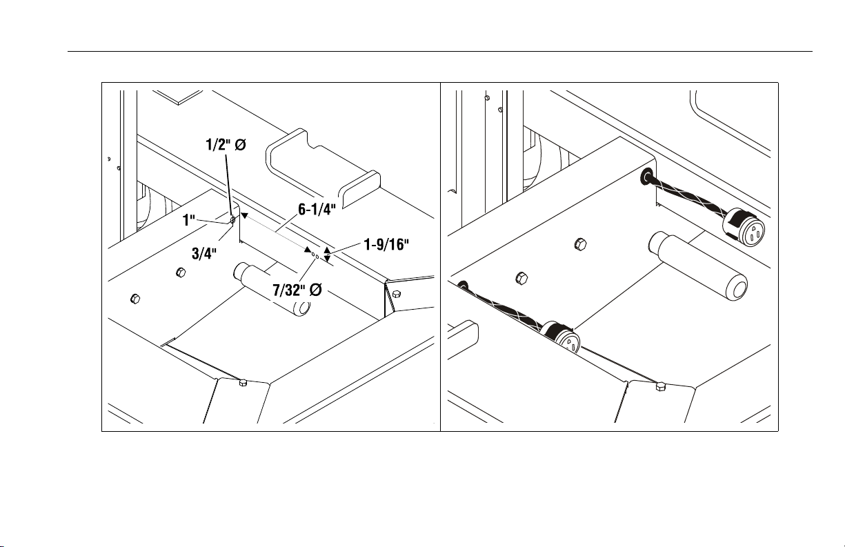
Straddle Adaptor Wiring Installation
1. Set up machine installing outriggers, level machine
and raise the platform as high as necessary to allow
access base frame.
NEVER WORK UNDER AN ELEVATED PLATFORM UNTIL PLATFORM HAS BEEN
SAFELY RESTRAINED FROM ANY MOVEMENT BY JACK STAND OR OVERHEAD
SLING.
2. Place a floor jack or other suitable support between
the mast and floor before working underneath platform.
ON AC MACHINES UNPLUG THE POWER CORD, DC POWERED MACHINES DISCONNECT THE MAIN POWER SUPPLY CONNECTOR ON THE SIDE OF THE BATTERY STORAGE/CHARGER BOX.
NOTE: The holes in the base frame for mounting the spring clips
and routing the wires through the center crossmember to
the interlock relay may already exist. If not continue with
Step 3, if holes are there, jump to Step 5.
3. Drill two (2) .219 diameter (7/32") holes per side for
each spring clip see Figure 5-2.
3121211 – JLG Lift – 5-3

SECTION 5 - OPTIONAL EQUIPMENT
4. Drill one (1) .50 diameter (1/2") hole, one (1) per side
into the center frame crossmember for the wiring
grommet see Figure 5-2.
5. Install the spring clips to the base frame at location of
drilled holes, using two (2) #10-24 x .625 bolts and
two (2) nuts and two (2) lock washers per spring clip.
6. Install the grommets supplied into the .50 dia. holes.
7. Locate the two short adapter wiring harnesses and
route one through each grommeted hole on the center frame crossmember.
8. Wire the adapter wiring harness ends together and to
the interlock relay wires as shown in Figure 5-3.
9. Press the two (2) - three (3) prong connector ends into
the spring clips mounted on the base frame.
10. Reconnect power to the machine and lower the platform to the stowed position. Stow the outriggers.
11. To verify installation, set-up and assemble straddle
extension as described in the Section 5-3. If outrigger
interlock LED’s on the straddle extension light up
when completely assembled, and power is supplied to
the platform, then installation is complete.
5-4 – JLG Lift – 3121211
SECTION 5 - OPTIONAL EQUIPMENT
Figure 5-2. SE-Adapter - Wiring - Grommet & Spring Clip Mounting Hole Locations.
(Same For Both Sides)
3121211 – JLG Lift – 5-5

SECTION 5 - OPTIONAL EQUIPMENT
2
3
1
4
G
S
G
S
RED 16
YEL 1
YEL 1
WHI TE 16
GREEN
YELLOW
YELLOW
YELLOW
GREEN 16
GREEN
BLACK
BLU
BLU
BLU
BLU
GREENGREEN
GREEN
BLACK
OUTPUT
B+
GRND.
1
3
4
2
++
Figure 5-3. Straddle Adapter Wiring Harness to AM Wiring Connections.
1. Grommet 3. Potted Relay
2. Crossmember 4. Butt Splice
NOTE: Cut (1) Green, (1) Yellow, and (1) Yellow 1 wire and install the Adapter Harness with butt splice terminals.
5-6 – JLG Lift – 3121211

SECTION 5 - OPTIONAL EQUIPMENT
5.3 AM-SE - STRADDLE EXTENSION – SET-UP AND OPERATION
Straddle Extension - Components
The AM-SE Straddle Extension can be set up by one person
without tools. The AM-SE consists of eight (8) structural components.
1. Two (2) extendable side lifting rails.
2. Two (2) end straddle supports on locking swivel caster
wheels, each with lifting winch and winch cables, outrigger interlock - retractable cable reel and quickrelease safety pins.
3. Four (4) short outrigger beams which interconnect the
straddle extension side lifting rails with the AM base
outrigger sockets.
Mounting - Straddle Extension to AM
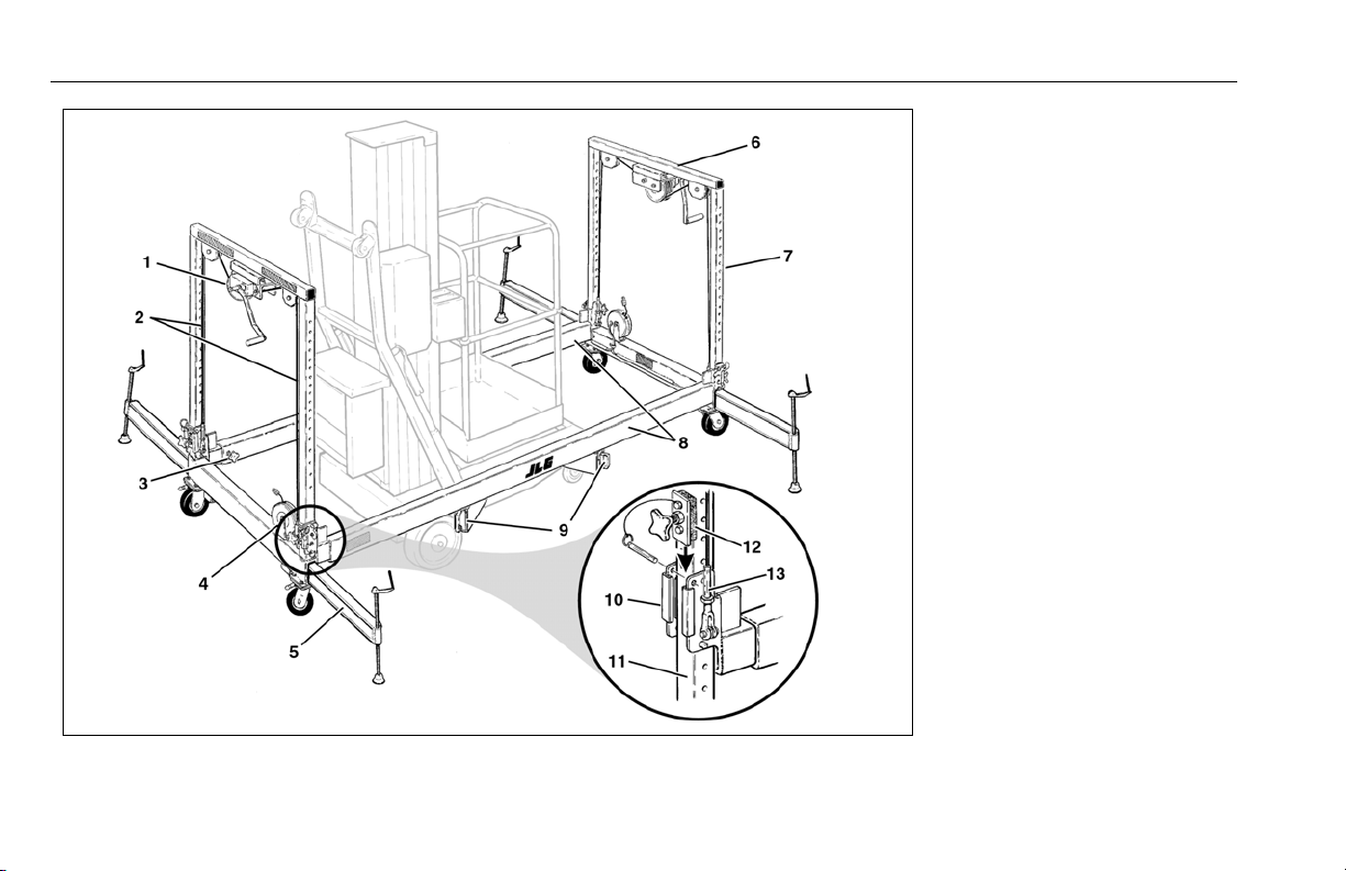
(See Figure 5-4.)
1. Near work area find a suitable area large enough to
assemble the AM machine to the Straddle Extension.
2. Insert one (1) of the short outrigger beams into an
outrigger socket in the AM base. Push it in until the
locking pin secures the beam in place.
3. Next, slide a side lifting rail onto the short outrigger
beam.
4. Align the side lifting rail with the other AM outrigger
socket on this side of the machine and install another
short outrigger beam. Push the short beam in until
the locking pin in the AM base secures the beam in
place.
5. Mount the remaining side lifting rail to the other side
of the AM machine repeating steps 2, 3 and 4.
6. Mount a straddle end support by aligning the two vertical rails of the end support with the adjust bracket
opening on ends of the side lifting rails.
NOTE: For added stability of the end support, lock the castor
wheels on the bottom of the support so they are parallel
with the outrigger sockets.
7. Insert end support vertical rails into the adjust brackets (in against the slide pads), and insert an adjust
bracket end cap (with slide pad against vertical rail)
into the slot on the adjust brackets on both side rails.
8. Secure end caps with the quick-release pin wired to
the end cap.
9. Repeat steps 6, 7 and 8 to mount the other straddle
end support.
10. Attach the winch lift cable clevis ends to the lifting
lugs, using the quick-release pins attached to winch
cables.
3121211 – JLG Lift – 5-7
SECTION 5 - OPTIONAL EQUIPMENT
1. Winch Assembly
2. Winch Lift Cables
3. Side Rail Locking Screw
4. Interlock Cable Reel
5. AM Unit Outriggers
6. Straddle End Support
7. Support Vertical Rail
8. Side Lifting Rails
9. Short Outrigger Beams
10. Adjust Bracket
11. Ve rtical R ail
12. Adjust Bracket End Cap and Pin
13. Cable Adjustable Clevis
Figure 5-4. Straddle Extension Component Assembly.
5-8 – JLG Lift – 3121211

SECTION 5 - OPTIONAL EQUIPMENT
NOTICE
11. Turn winch handle clockwise just enough to start lift-
ing side rails. Both cables must be lifting evenly.
If not lifting evenly, adjust slack out of long cable by:
a. Lowering side rails by turning the winch handle
enough to remove any tension on the winch cables.
b. Remove the quick-release pin securing the winch cable
clevis to the lifting lug on the side rail adjust bracket.
c. Loosen the jam nut on the threaded cable end and turn
the clevis end clockwise to shorten the cable.
d. Before tightening the jam nut re-install the winch cable
to the side rail lifting lug with the quick release pin.
e. Turn winch handle to start lifting side rails, again
observe winch cables. If cables are lifting evenly,
retighten jam nut on threaded end of winch cable. If
not lifting evenly repeat steps.
12. Connect the outrigger interlock cable ends from the
retractable reels to the straddle adapter connector
ends mounted on the AM base frame under the platform.
Positioning Straddle Unit and Lifting AM Machine
WHEN EXTENDING SIDE LIFTING RAILS, DO NOT OVER EXTEND THE RAILS
INTO THE RED ZONE PAINTED ON THE RAILS.
With Straddle Extension installed to the AM machine properly
the unit can be moved to it’s work location. Make any final
adjustments to the Straddle Extension before lifting the AM
machine.
1. Use the following steps to lift the AM machine:
NOTE: When winching, raise or lower each end of the straddle
extension as evenly as possible to avoid binding the vertical rails in the lift rail end brackets.
a. Firmly grasp the handle on winch assembly and turn
winch arm clockwise.
b. When desired height has been reached, align the holes
to allow the quick-release pins to be inserted securing
side rails in position.
c. When all pins are inserted and locked, crank winch han-
dles counter-clockwise to release tension on the winch
cables.
d. Remove any end to end play in straddle unit by tighten-
ing the adjust bracket end cap - adjustment screws.
3121211 – JLG Lift – 5-9

SECTION 5 - OPTIONAL EQUIPMENT
DANGER
2. With AM, Straddle Extension assembly in position,
install the AM outriggers on each end of the Straddle
Extension.
3. Level the AM and Straddle Extension Unit with the
outrigger leveling jacks using the bubble level indicator located on the AM base frame.
4. Turn on the power switch at the ground control station on AM unit. Ensure the outrigger interlock LED’s
located on the straddle end supports are illuminated.
5. If all four (4) interlock LED’s are illuminated the unit is
ready for operation.
6. Prior to entering the platform insure the lift is properly
set up and ready for use by checking:
a. All short outrigger beam adapters are locked and
secured.
b. Side rail adjust bracket locking pins are installed and
tension is released from winch cables.
c. Adjust bracket end cap adjust screws have been tight-
ened.
d. Straddle and AM are leveled.
NOTE: The AM-SE Ladder (option) is available to ease entry into
the AM platform. The ladder is attached to either straddle
side lifting rail on the straddle extension.
DO NOT ATTEMPT TO MOVE THE STRADDLE UNIT AROUND WITH THE AM
MACHINE PLATFORM IN A ELEVATED POSITION.
Lowering AM Machine on Straddle Unit
1. With platform in stowed position, remove the outriggers and move the straddle and AM unit to an open
area.
2. Loosen adjust screws on adjust bracket end caps (See
Figure 5-5.).
3. Crank the winch handle on each winch (located on
straddle end supports) clockwise, just enough to start
raising the side lifting rails, lifting the weight off of the
quick-release pins installed through the side rail adjust
bracket and the straddle end support vertical rails.
4. Remove ONLY the two (2) SIDE RAIL QUICK-RELEASE
PINS installed through each side lifting rail adjust
bracket, and the straddle end support vertical rails at
all four (4) corners of the straddle extension. (See Fig-
ure 5-5.)
* DO NOT REMOVE THE END CAP PIN FROM THE ADJUST BRACKET UNTIL THE
AM MACHINE IS FULLY LOWERED TO THE GROUND ON ITS CASTOR WHEELS,
5-10 – JLG Lift – 3121211

AND STRADDLE END SUPPORTS ARE BEING DISASSEMBLED FROM SIDE
RAILS. (SEE FIGURE 5-5.)
5. Carefully lower the side lifting rails (and AM machine)
evenly, by turning the winch handle at each straddle
end support counter-clockwise until the AM machine
is fully lowered to the ground on it’s caster wheels.
Straddle and AM Machine Disassembly
Once the AM machine is lowered on its castor wheels and outriggers are removed, reverse steps on "Mounting - Straddle
Extension to AM Machine", steps 1 through 12.
SECTION 5 - OPTIONAL EQUIPMENT
Figure 5-5. Side Lifting Rail - Quick Release Pins.
1. Adjust Bracket End Cap Pin (* SEE WARNING)
2. End Cap Adjust Screw
3. Side Rail Quick-Release Pins
3121211 – JLG Lift – 5-11

SECTION 5 - OPTIONAL EQUIPMENT
NOTES:
5-12 – JLG Lift – 3121211

SECTION 6 - EMERGENCY PROCEDURES
NOTICE
SECTION 6. EMERGENCY PROCEDURES
6.1 GENERAL INFORMATION
This section explains the steps to be taken in case of an emergency situation while operating the machine.
6.2 EMERGENCY OPERATION
Operator Unable to Control Machine
IF THE PLATFORM OPERATOR IS PINNED, TRAPPED OR UNABLE
TO OPERATE OR CONTROL THE MACHINE, USE THE FOLLOWING
INSTRUCTIONS AS A GUIDELINE.
1. Other personnel should operate the machine from
ground controls only as required.
2. Only qualified personnel in the platform may use the
platform controls. DO NOT CONTINUE OPERATION IF
CONTROLS DO NOT FUNCTION PROPERLY.
3. Cranes, forklift trucks or other equipment can be used
to remove the platform occupant and stabilize motion
of the machine.
3121211 – JLG Lift – 6-1
Platform Caught Overhead
If the platform becomes jammed or snagged in overhead structures or equipment, rescue the platform occupant prior to freeing the machine.
Righting of Tipped Machine
Before righting a tipped machine, check machine for any damage which may prevent it from setting properly on its base
wheels once in a vertical position, (i.e. base wheels damaged,
base frame distorted, etc.). Use a crane, forklift or other suitable
lifting equipment and carefully lift the machine to an upright
position.
FOLLOWING ANY INCIDENT, THOROUGHLY INSPECT THE MACHINE AND TEST
ALL FUNCTIONS. DO NOT LIFT ABOVE 10 FEET (3 METERS) UNTIL YOU ARE
SURE THAT ALL DAMAGE HAS BEEN REPAIRED, IF REQUIRED, AND THAT ALL
CONTROLS ARE OPERATING CORRECTLY.

SECTION 6 - EMERGENCY PROCEDURES
6.3 INCIDENT NOTIFICATION
JLG Industries, Inc. must be notified immediately of any incident
involving a JLG product. Even if no injury or property damage is
evident, the factory should be contacted by telephone and provided with all necessary details.
JLG Phone:
USA: 877-JLG-SAFE (554-7233)
(8am till 4:45pm EST)
EURO: 011 44 1 698 811005
AUSTRALIA: 011 61 2 65 811111
E-mail (USA): productsafety@jlg.com
Failure to notify the Manufacturer of an incident involving a JLG
Industries product within 48 hours of such an occurrence may
void any warranty consideration on that particular machine.
6-2 – JLG Lift – 3121211

SECTION 7 - GENERAL SPECIFICATIONS AND OPERATOR MAINTENANCE
SECTION 7. GENERAL SPECIFICATIONS AND OPERATOR MAINTENANCE
7.1 INTRODUCTION
This section of the manual provides additional necessary information to the operator for proper operation and maintenance
of this machine.
The maintenance portion of this section is intended as information to assist the machine operator to perform daily maintenance tasks only, and does not replace the more thorough
Preventive Maintenance and Inspection Schedule included in
the Service and Maintenance Manual.
Other Publications Available Specific to this Machine:
Service and Maintenance Manual
ANSI . . . .. . . .. . . .. . . .. . . . . . . . . . . .. . . .. . . .. . . . . . 3120752
CE . . . . . .. . . .. . . .. . . .. . . . . . . . . . . .. . . .. . . .. . . . . . 3120872
Illustrated Parts Manual
ANSI . . . .. . . .. . . .. . . .. . . . . . . . . . . .. . . .. . . .. . . . . . 3120753
CE . . . . . .. . . .. . . .. . . .. . . . . . . . . . . .. . . .. . . .. . . . . . 3120873
3121211 – JLG Lift – 7-1

SECTION 7 - GENERAL SPECIFICATIONS AND OPERATOR MAINTENANCE
7.2 GENERAL SPECIFICATIONS
Machine Specifications
SPECIFICATION 20AM 25AM 30AM 36AM 41AM
Gross Machine Weight (Platform Empty): DC: 785 lb.
(356kg)
AC: 7 17 lb.
(325kg)
Machine Height (Platform Stowed)
* Machine Height in Tilt-Back Mode
Maximum Outrigger Pad Load:
(per outrigger)
Outrigger Footprint: (Length x Width) 62 x 54 in.
Machine Base - Overall : (Length x Width) 47 x 29 in.(1.19m
Maximum Wind Speed: 0 mph (0kph) - Machine rated for indoor use only
Maximum Horizontal Manual Side Force:
(Platform fully extended with Maximum load)
Maximum Hydraulic System Pressure: Pressure Relief Set to 2800 PSI (193 bar) at Factory
7-2 – JLG Lift – 3121211
77.3 in.
(2m)
386 lb.
(175kg)
(1.57 x 1.37 m)
x 74cm)
871 lb.
(395kg)
800 lb.
(363kg)
77.3 in.
(2m)
410 lb.
(186kg)
49 x 29 in.
(1.24m x 74cm)
45 Pound Force (2 00 Newtons)
941 lb.
(427kg)
871 lb.
(395kg)
77.3 in.
(2m)
396 lb.
(180kg)
68 x 62 in.
(1.72 x 1.57 m)
52 x 29 in.
(1.32m x 74cm)
1043 lb.
(473kg)
973 lb.
(441kg)
*77 in. (2m)
104.3 in. (2.64m)
390 lb.
(177kg)
79 x 79 in.
(2 x 2m)
54.5 x 29 in.
(1.38m x 74cm)
1142 lb. (518kg)
1072 lb. (486kg)
*77 in. (2m)
104.3 in. (2.64m)
412 lb.
(187kg)
79 x 79 in.
(2 x 2m)
57.5 x 29 in.
(1.46m x 74cm)
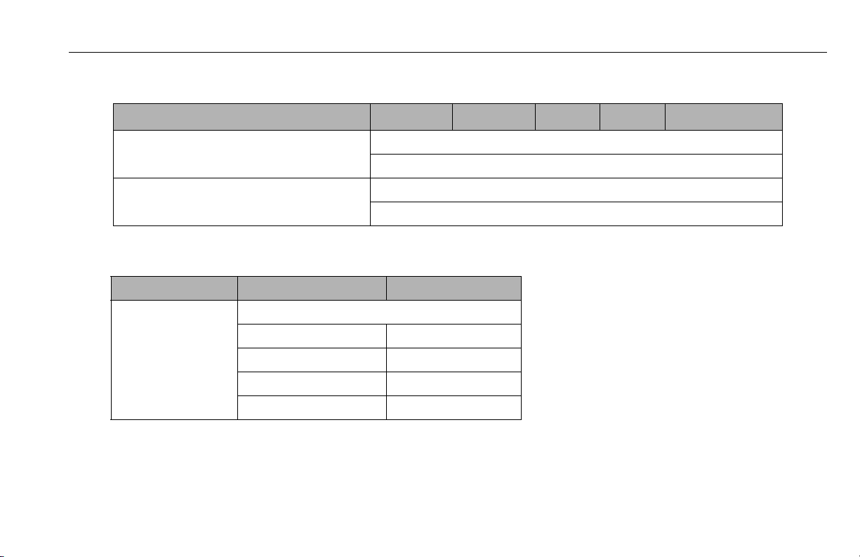
Electrical Specifications
SPECIFICATION 20AM 25AM 30AM 36AM 41AM
Sy s te m V ol t ag e : DC M od e ls : 12 Vo l ts D C
Battery Charger (DC Models) In pu t : 12 0 /2 40 Vo l ts AC - 50 /6 0 Hz - Vo lt ag e Se l ec t ab l e
Battery Specifications
Battery Type: WET/DRY COMBO AGM ( VRLA )
Vol tag e: 12 Volt s DC
Amp Hour (AH) Rating: 105 Amp Hr. @ 20 Hr. 100 Amp Hr. @ 20 Hr.
Reserve Capacity: 165 Min. N/A
Cold Cranking Amps: 625 Amps @ 0° F N/A
Weight: 54 lb. (24kg) 78 lb. (35kg)
SECTION 7 - GENERAL SPECIFICATIONS AND OPERATOR MAINTENANCE
AC Models: 100/120/240 Volts AC
Output: 12 Volt - 10 Amps DC - w/Auto Charge Sensing Circuit
3121211 – JLG Lift – 7-3

SECTION 7 - GENERAL SPECIFICATIONS AND OPERATOR MAINTENANCE
Platform Data
SPECIFICATION 20AM 25AM 30AM 36AM 41AM
Occupants: (Persons allowed in Platform) 1
Pl a tf o rm Ca p ac i ty : AN SI /C . S. A :
(U.S.A, Brazil, Japan, China, Latin America and C.S.A. - Canada: B3 54.1-04)
350 lb.
(160 kg)
350 lb.
(160 kg)
350 lb.
(160 kg)
300 lb.
(135 kg)
300 lb.
(135 kg)
CE:
( Europe, Aust rali a)
C.S.A.:
(C.S.A. - Canada: B354.1-M82)
Platform Height - Mast Fully Extended - (Ground to Platform Floor):20 ft.
Platform Working Height - (Average Size Person): 26 ft.
Platform Cycle Performance -(in seconds) (w/max. rated load)
Fenner B rand Pump - Lift Up: 50 62 72 128 120
Monarch Brand Pump - Lift Up: (DC) 51 57 67 97 101
Monarch Brand Pump -Lift Up: (AC) 70 73 80 110 108
Lift Down: 32-42 32-42 32-42 47-57 45-55
7-4 – JLG Lift – 3121211
350 lb.
(160 kg)
300 lb.
(135 kg)
(6.09 m)
(7.9 m)
350 lb.
(160 kg)
300 lb.
(135 kg)
25 ft.
(7.62 m)
31 ft.
(9.4 m)
300 lb.
(135 kg)
300 lb.
(135 kg)
30 ft.
(9.14 m)
36 ft.
(11 m)
300 lb.
(135 kg)
250 lb.
(113 kg)
36 ft.
(11 m)
42 ft.
(12.8 m)
300 lb.
(135 kg)
250 lb.
(113 kg)
41 ft.
(12.42 m)
47 ft.
(14.3 m)
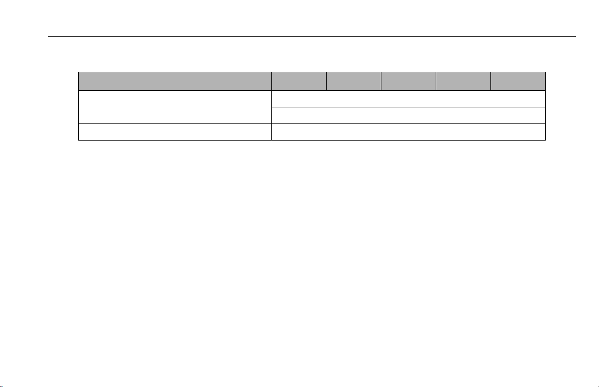
SECTION 7 - GENERAL SPECIFICATIONS AND OPERATOR MAINTENANCE
Machine Component Weights
SPECIFICATION 20AM 25AM 30AM 36AM 41AM
Pl a tf o rm We ig h t : S t an d ar d P l at fo r m: 5 5 l b. ( 25 kg)
(Quick- Change Platfor ms) Mo ld e d P l at fo r m: 7 0 l b. (3 2 kg )
DC Voltage Battery Pack: (Wet Cell) 70 lb. (32 kg)
Serial Number Locations
For machine identification, a serial number plate is affixed to the
machine. The plate is located on the back of the mast, just
above the mast support bracket.
3121211 – JLG Lift – 7-5
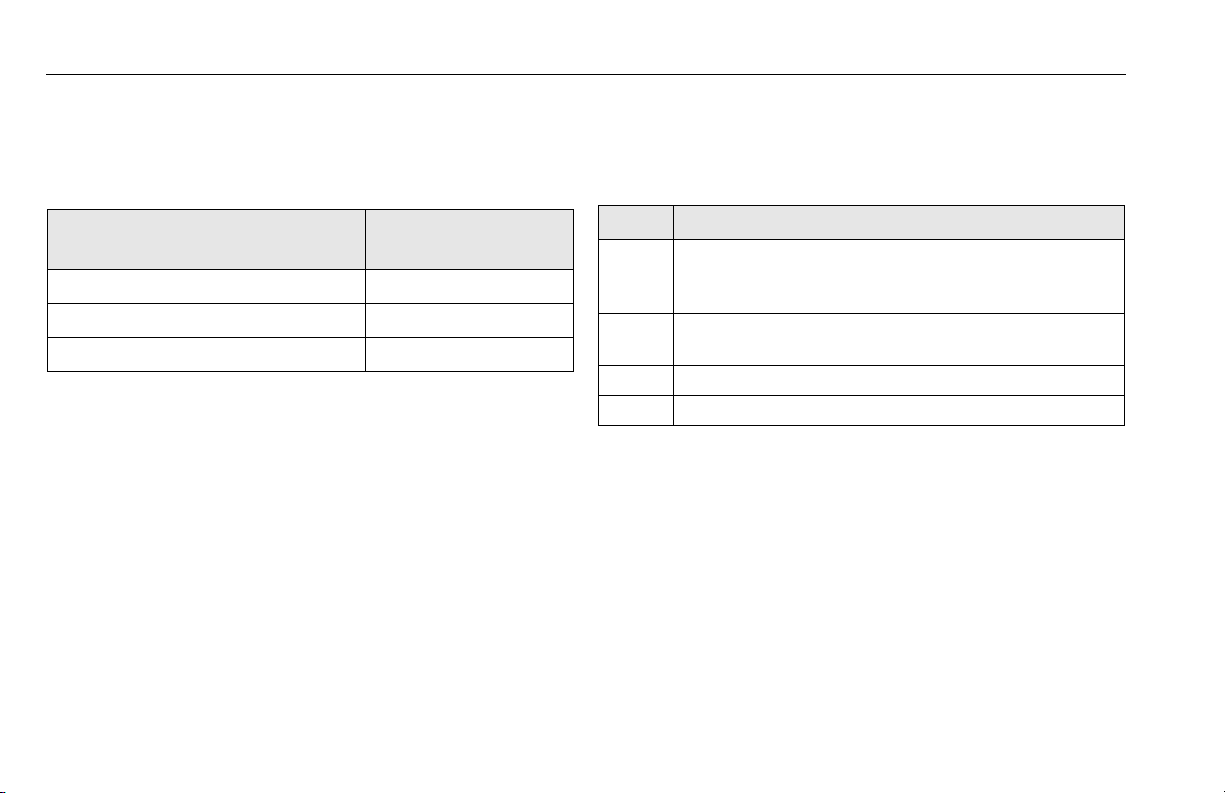
SECTION 7 - GENERAL SPECIFICATIONS AND OPERATOR MAINTENANCE
7.3 OPERATOR MAINTENANCE
Lubrication
Hydraulic Oil (HO)
Table 7-1. - Lubrication Specifications
HYDRAULIC SYSTEM OPERATING
TEMPERATURE RANGE
+0° F to +180° F (-18° C to -83° C) 10W
+0° F to +210° F (-18° C to +99° C) 10W-20, 10W-30
+50° F to +210° F (+10° C to +99° C) 20W-20
Hydraulic oils must have anti-wear qualities at least to API Service Classification GL-3, and sufficient chemical stability for
mobile hydraulic system service. JLG Industries, recommends
Mobilfluid 424 hydraulic oil, which has an SAE viscosity of 10W30 and a viscosity index of 152.
For cold weather applications, i.e. when temperatures remain
consistently below +20°F (–7°C) JLG recommends using Mobil
DTE 13 hydraulic oil.
Aside from JLG recommendations, it is not advisable to mix oils
of different brands or types, as they may not contain the same
required additives or be of comparable viscosities. If use of
hydraulic oil other than Mobilfluid 424 is desired, contact JLG
Industries for proper recommendations.
7-6 – JLG Lift – 3121211
SAE VISCOSITYGRADE
KEY SPECIFICATIONS
MPG - Multipurpose Grease having a minimum dripping point of 350° F. Excel-
lent water resistance and adhesive qualities, and being of extreme pressure type. (Timken OK 40 pounds minimum.)
EPGL - Extreme Pressure Gear Lube (oil) meeting API service classification GL-5
or MIL-Spec MIL-L-2105.
HO - Hydraulic Oil. ISO-Vg grade 32, 46.
CL - Chain Lube. Use a good quality chain lubricant
NOTE: Refer to Lubrication Chart, Table 7-2 for specific lubrication
locations on machine.

CAUTION
1/8 "
(3 mm)
1
3
2
4
SECTION 7 - GENERAL SPECIFICATIONS AND OPERATOR MAINTENANCE
Battery Maintenance
NOTE: This information applies to wet cell batteries only. Do not
attempt to open a maintenance-free sealed battery.
Battery fluid level should be approximately 1/8" (3mm) below
vent tubes. (See Illustration)
Keep cable connections clean and free of corrosion.
BATTERY ACID IS HIGHLY CORROSIVE. AVOID CONTACT WITH SKIN AND
CLOTHING AT ALL TIMES.
BATTERY ACID RELEASES AN EXPLOSIVE GAS WHILE CHARGING, ALLOW NO
OPEN FLAMES, SPARKS OR LIGHTED TOBACCO PRODUCTS IN THE AREA WHILE
CHARGING BATTERIES. CHARGE BATTERIES ONLY IN A WELL VENTILATED
AREA.
ADD ONLY DISTILLED WATER TO BATTERIES. WHEN ADDING DISTILLED WATER
TO THE BATTERIES, A NON-METALLIC CONTAINER AND/OR FUNNEL MUST BE
USED.
Battery Fluid Level
1. Battery Filler Cap 3. Fluid Level
2. Vent Tube 4. Cell Plates
3121211 – JLG Lift – 7-7

SECTION 7 - GENERAL SPECIFICATIONS AND OPERATOR MAINTENANCE
1
4
2
3
7-8 – JLG Lift – 3121211
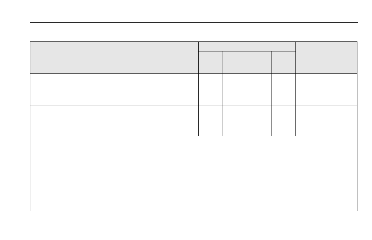
SECTION 7 - GENERAL SPECIFICATIONS AND OPERATOR MAINTENANCE
Table 7-2. - Lubrication Intervals for Various Components
INTERVAL HOURS
ITEM COMPONENT
1 Hydraulic Oil
2 Swivel Raceways 2 - Front Casters MPG - Pressure Gun
Leveling Jack
3
Screws
4 Mast Chains * 2 - Per Section CL - Brush or Spray
* Applies Only to Mast Sections with Chains.
Key to Lubricants: MPG - Multipurpose Grease
HO - Hydraulic Oil - ISO-Vg grade 32, 46.
CL - Chain Lube. Use a good quality chain lubricant
Notes: 1. Be certain to lubricate like items on each side of the machine.
2. Recommended lubricating intervals are based on normal use. If machine is subjected to severe operating conditions,
such as a high number of cycles, location, corrosive/dirty environment, etc., user must adjust lubricating requirements accordingly.
3. Lubricating intervals are calculated on 50 hours of machine operation a week.
4. Prior to checking hydraulic oil level, operate machine through one complete cycle of lift function (full up and down). Failure to do so will
result in incorrect oil level reading on the hydraulic reservoir.
NO/TYPE
LUBE POINTS
Fill To Line on Reser voir
5 Qt. (4.3 L) Reservoir
4 - Jack Threads MPG - Brush
LUBE/ METHOD
HO/Check Hydraulic
Oil Level HO/Change Hydraulic
Oil
3
MONTHS
150 Hrs.
6
MONTHS
300 Hrs.
X
X
X Inspect, lubricate if drying or
1
YEAR
600 Hrs.
2
YEARS
1200 Hrs.
X
COMMENTS
Check oil level every day.
Change hydraulic oil every
2 years.
rusting.
3121211 – JLG Lift – 7-9

SECTION 7 - GENERAL SPECIFICATIONS AND OPERATOR MAINTENANCE
7.4 SUPPLEMENTAL INFORMATION
The following information is provided in accordance with the
requirements of the European Machinery Directive 2006/42/EC
and is only applicable to CE machines.
For electric powered machines, the equivalent continuous AWeighted sound pressure level at the work platform is less than
70dB(A).
For combustion engine powered machines, guaranteed Sound
Power Level (LWA) per European Directive 2000/ 14/EC (Noise
Emission in the Environment by Equipment for Use Outdoors)
based on test methods in accordance with Annex III, Part B,
Method 1 and 0 of the directive, is 109 dB.
The vibration total value to which the hand-arm system is subjected does not exceed 2,5 m/s2. The highest root mean square
value of weighted acceleration to which the whole body is subjected does not exceed 0,5 m/s2.
7-10 – JLG Lift – 3121211

SECTION 8. INSPECTION AND REPAIR LOG
Table 8-1. Inspection and Repair Log
DATE COMMENTS
SECTION 8 - INSPECTION AND REPAIR LOG
Machine Serial Number: _________________________
3121211 – JLG Lift – 8-1

SECTION 8 - INSPECTION AND REPAIR LOG
Table 8-1. Inspection and Repair Log
DATE COMMENTS
Machine Serial Number: _________________________
8-2 – JLG Lift – 3121211

TRANSFER OF OWNERSHIP
To Product Owner:
If you now own but ARE NOT the original purchaser of the product covered by this
manual, we would like to know who you are. For the purpose of receiving safety-related
bulletins, it is very important to keep JLG Industries, Inc. updated with the current
ownership of all JLG products. JLG maintains owner information for each JLG product
and uses this information in cases where owner notification is necessary.
Please use this form to provide JLG with updated information with regard to the
current ownership of JLG products. Please return completed form to the JLG Product
Safety & Reliability Department via facsimile or mail to address as specified below.
Thank You,
Product Safety & Reliability Department
JLG Industries, Inc.
13224 Fountainhead Plaza
Hagerstown, MD 21742
USA
Telephone: +1-717-485-6591
Fax: +1-301-745-3713
NOTE: Leased or rented units should not be included on this form.
Mfg. Model: _____________
__________________________________________________
Serial Number: ____________________________________________________________
Previous Owner: ___________________________________________________________
Address: _________________________________________________________________
_________________________________________________________________________
Country: _________________________ Telephone: (_______
) ____________________
Date of Transfer: _________________________________
Current Owner: ____________________________________________________________
Address: _______________
__________________________________________________
_________________________________________________________________________
Country: _________________________ Telephone: (_______
) ____________________
Who in your organization should we notify?
Name: ___________________________________________________________________
Title:_____________________________________________________________________
An Oshkosh Corporation Company

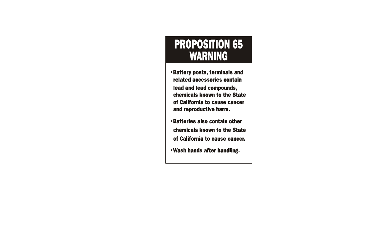

JLG Worldwide Locations
3121211
JLG Industries (Australia)
P.O. Box 5119
11 Bolwarra Road
Port Macquarie
N.S.W. 2444
Australia
+61 2 65 811111
+61 2 65 810122
JLG Deutschland GmbH
Max-Planck-Str. 21
D - 27721 Ritterhude - Ihlpohl
Germany
+49 (0)421 69 350 20
+49 (0)421 69 350 45
Plataformas Elevadoras
JLG Iberica, S.L.
Trapadella, 2
P.I. Castellbisbal Sur
08755 Castellbisbal, Barcelona
Spain
+34 93 772 4700
+34 93 771 1762
JLG Latino Americana Ltda.
Rua Eng. Carlos Stevenson,
80-Suite 71
13092-310 Campinas-SP
Brazil
JLG Equipment Services Ltd.
Rm 1107 Landmark North
39 Lung Sum Avenue
Sheung Shui N. T.
Hong Kong
JLG Sverige AB
Enkopingsvagen 150
Box 704
SE - 176 27 Jarfalla
Sweden
JLG Industries, Inc.
1 JLG Drive
McConnellsburg PA. 172339533
USA
(717) 485-5161
(717) 485-6417
+55 19 3295 0407
+55 19 3295 1025
(852) 2639 5783
(852) 2639 5797
+46 (0)850 659 500
+46 (0)850 659 534
JLG Industries (UK) Ltd
Bentley House
Bentley Avenue
Middleton
Greater Manchester
M24 2GP - England
+44 (0)161 654 1000
+44 (0)161 654 1001
JLG Industries (Italia) s.r.l.
Via Po. 22
20010 Pregnana Milanese - MI
Italy
+39 029 359 5210
+39 029 359 5845
JLG France SAS
Z.I. de Baulieu
47400 Fauillet
Franc e
+33 (0)5 53 88 31 70
+33 (0)5 53 88 31 79
JLG Europe B.V.
Polaris Avenue 63
2132 JH Hoofddorp
Netherlands
+31 (0)23 565 5665
+31 (0)23 557 2493
www.jlg.com
 Loading...