


JLG 4394RT Parts Manual
Illustrated Parts Manual
Models
3394RT
& 4394RT
SN 0200191606
to Present
P/N
3121250
February 7, 2014


REVISION LOG
NOTE: Machines SN 0200186972, 0200187002 & 0200187013 are also built to specs contained in this manual.
NOTE: Machines SN 0200186972, 0200187002, 0200187013 & All Machines 0200191606 to Present are built to
B/M 0010583 Revision 56 or higher.
October 15, 2008 - Original Issue Of Manual (Manual edited to B/M 0010583 Revision 57)
January 1, 2009 - Revised Manual (Manual edited to B/M 0010583 Revision 62)
June 1, 2009 - Revised Manual (Manual edited to B/M 0010583 Revision 64)
October 1, 2010 - Revised Manual (Manual edited to B/M 0010583 Revision 69)
March 23, 2011 - Revised Manual (Manual edited to B/M 0010583 Revision 70)
June 16, 2011 - Revised Manual (Manual edited to B/M 0010583 Revision 72)
September 22, 2011 - Revised Manual (Manual edited to B/M 0010583 Revision 74)
February 14, 2012 - Revised Manual (Manual edited to B/M 0010583 Revision B)
June 27, 2012 - Revised Manual (Manual edited to B/M 0010583 Revision C)
September 7, 2012 - Revised Manual (Manual edited to B/M 0010583 Revision C)
January 21, 2013 - Revised Manual (Manual edited to B/M 0010583 Revision C)
April 30, 2013 - Revised Manual (Manual edited to B/M 0010583 Revision M)
July 22, 2013 - Revised Manual (Manual edited to B/M 0010583 Revision M)
October 14, 2013 - Revised Manual (Manual edited to B/M 0010583 Revision M)
February 7, 2014 - Revised Manual (Manual edited to B/M 0010583 Revision S & B/M 1001160090 Revision B)
3121250 3394RT & 4394RT A

REVISION LOG
B 3394RT & 4394RT 3121250

TABLE OF CONTENTS
FIGURE NO. TITLE PAGE NO.
SECTION 1 - FRAME . . . . . . . . . . . . . . . . . . . . . . . . . . . . . . . . . . . . . . . . . . . . . . . . . . . . . .1-1
1-1 AXLE AND STEERING INSTALLATION WITHOUT TOW PACKAGE
(SN 0200191606 TO SN 0200223954). . . . . . . . . . . . . . . . . . . . . . . . . . . . . . . . . . . 1-2
1-2 AXLE AND STEERING INSTALLATION WITHOUT TOW PACKAGE
(SN 0200223954 TO PRESENT)1-6
1-3 AXLE AND STEERING INSTALLATION WITH TOW PACKAGE . . . . . . . . . . . . . . . . . . 1-8
1-4 TIRE AND WHEEL DRIVE INSTALLATIONS . . . . . . . . . . . . . . . . . . . . . . . . . . . . . . . . . 1-14
1-5 DRIVE MOTOR/HUB ASSEMBLY (REXROTH) . . . . . . . . . . . . . . . . . . . . . . . . . . . . . . . 1-18
1-6 DRIVE MOTOR ASSEMBLY (SAUER-DANFOSS). . . . . . . . . . . . . . . . . . . . . . . . . . . . . 1-22
1-7 DRIVE HUB ASSEMBLIES (FAIRFIELD) . . . . . . . . . . . . . . . . . . . . . . . . . . . . . . . . . . . . 1-24
1-8 BEACON LIGHT & LEVELING JACKS INSTALLATION. . . . . . . . . . . . . . . . . . . . . . . . . 1-28
SECTION 2 - GROUND CONTROLS . . . . . . . . . . . . . . . . . . . . . . . . . . . . . . . . . . . . . . . . . .2-1
2-1 CONTROL VALVES, HORN & ALARMS INSTALLATIONS . . . . . . . . . . . . . . . . . . . . . . 2-2
2-2 MAIN CONTROL VALVE ASSEMBLY . . . . . . . . . . . . . . . . . . . . . . . . . . . . . . . . . . . . . . 2-6
2-3 FLOW DIVIDER VALVE ASSEMBLY . . . . . . . . . . . . . . . . . . . . . . . . . . . . . . . . . . . . . . . 2-8
2-4 LEVELING JACK VALVE ASSEMBLY . . . . . . . . . . . . . . . . . . . . . . . . . . . . . . . . . . . . . . 2-10
2-5 ENGINE INSTALLATION (DEUTZ D2011 ENGINE) . . . . . . . . . . . . . . . . . . . . . . . . . . 2-12
2-6 ENGINE INSTALLATION (DEUTZ D2.9l4 ENGINE) . . . . . . . . . . . . . . . . . . . . . . . . . . 2-20
2-7 ENGINE INSTALLATION (GM) (SN 0200191606 to SN 0200198947) . . . . . . . . . . . . . 2-30
2-8 ENGINE INSTALLATION (GM) (SN 0200198947 to PRESENT) . . . . . . . . . . . . . . . . . . 2-36
2-9 PISTON PUMP ASSEMBLY. . . . . . . . . . . . . . . . . . . . . . . . . . . . . . . . . . . . . . . . . . . . . . 2-42
2-10 AUXILIARY PUMP ASSEMBLY . . . . . . . . . . . . . . . . . . . . . . . . . . . . . . . . . . . . . . . . . . . 2-46
2-11 TANKS AND TANK TRAY INSTALLATION. . . . . . . . . . . . . . . . . . . . . . . . . . . . . . . . . . . 2-48
2-12 GROUND CONTROL BOX INSTALLATION. . . . . . . . . . . . . . . . . . . . . . . . . . . . . . . . . . 2-52
2-13 HOODS AND LADDERS INSTALLATIONS . . . . . . . . . . . . . . . . . . . . . . . . . . . . . . . . . . 2-56
2-14 GENERATOR INSTALLATION (DEUTZ D2011ENGINE OPTIONS) . . . . . . . . . . . . . . . 2-62
2-15 7500W GENERATOR INSTALLATION (DEUTZ D2.9L4 ENGINE OPTIONS) . . . . . . . . 2-66
2-16 GENERATOR INSTALLATION (GM ENGINE OPTIONS) . . . . . . . . . . . . . . . . . . . . . . . 2-70
SECTION 3 - SCISSORS ARMS . . . . . . . . . . . . . . . . . . . . . . . . . . . . . . . . . . . . . . . . . . . . .3-1
3-1 SCISSORS ARMS INSTALLATION (3394RT) . . . . . . . . . . . . . . . . . . . . . . . . . . . . . . . . 3-2
3-2 SCISSOR ARMS INSTALLATION (4394RT) . . . . . . . . . . . . . . . . . . . . . . . . . . . . . . . . . 3-8
3-3 ARM GUARDS INSTALLATION (CE SPEC ONLY) . . . . . . . . . . . . . . . . . . . . . . . . . . . . 3-14
SECTION 4 - PLATFORM. . . . . . . . . . . . . . . . . . . . . . . . . . . . . . . . . . . . . . . . . . . . . . . . . . .4-1
4-1 PLATFORM ATTACH AND MODULE INSTALLATIONS . . . . . . . . . . . . . . . . . . . . . . . . 4-2
4-2 MANUAL SINGLE DECK EXTENSION AND PLATFORM ASSEMBLY . . . . . . . . . . . . . 4-4
4-3 MANUAL DUAL DECK EXTENSION AND PLATFORM ASSEMBLY . . . . . . . . . . . . . . . 4-8
4-4 POWER DECK EXTENSION AND PLATFORM ASSEMBLY . . . . . . . . . . . . . . . . . . . . . 4-12
4-5 RAILS INSTALLATION . . . . . . . . . . . . . . . . . . . . . . . . . . . . . . . . . . . . . . . . . . . . . . . . . . 4-18
4-6 PLATFORM CONSOLE BOX ASSEMBLY . . . . . . . . . . . . . . . . . . . . . . . . . . . . . . . . . . . 4-22
4-7 DRIVE/STEER CONTROLLER ASSEMBLY . . . . . . . . . . . . . . . . . . . . . . . . . . . . . . . . . . 4-26
3121250 3394RT & 4394RT i

TABLE OF CONTENTS
FIGURE NO. TITLE PAGE NO.
SECTION 5 - CYLINDER . . . . . . . . . . . . . . . . . . . . . . . . . . . . . . . . . . . . . . . . . . . . . . . . . . .5-1
5-1 AXLE LOCKOUT CYLINDER ASSEMBLY . . . . . . . . . . . . . . . . . . . . . . . . . . . . . . . . . . . 5-2
5-2 LEVELING JACK CYLINDER ASSEMBLY . . . . . . . . . . . . . . . . . . . . . . . . . . . . . . . . . . . 5-4
5-3 LIFT CYLINDER ASSEMBLY . . . . . . . . . . . . . . . . . . . . . . . . . . . . . . . . . . . . . . . . . . . . . 5-6
5-4 PLATFORM EXTENSION CYLINDER ASSEMBLY. . . . . . . . . . . . . . . . . . . . . . . . . . . . . 5-10
5-5 STEER CYLINDER ASSEMBLY (SN 0200191606 TO SN 0200223954) . . . . . . . . . . . . 5-12
5-6 STEER CYLINDER ASSEMBLY (SN 0200223954 TO PRESENT) . . . . . . . . . . . . . . . . . 5-14
SECTION 6 - HYDRAULIC . . . . . . . . . . . . . . . . . . . . . . . . . . . . . . . . . . . . . . . . . . . . . . . . . .6-1
6-1 STANDARD HYDRAULIC DIAGRAM - STANDARD (REXROTH DRIVE
COMPONENTS) (SN 0200191606 TO SN 0200207753) . . . . . . . . . . . . . . . . . . . . . 6-2
6-2 STANDARD HYDRAULIC DIAGRAM - STANDARD (SAUER-DANFOSS/
FAIRFIELD DRIVE COMPONENTS) (SN 0200207753 TO PRESENT) . . . . . . . . . . . 6-6
6-3 LEVELING JACK HYDRAULIC DIAGRAM . . . . . . . . . . . . . . . . . . . . . . . . . . . . . . . . . . . 6-10
6-4 POWER DECK EXTENSION HYDRAULIC DIAGRAM (SN 0200191606 TO
SN 0200210269) . . . . . . . . . . . . . . . . . . . . . . . . . . . . . . . . . . . . . . . . . . . . . . . . . . . . 6-12
6-5 POWER DECK EXTENSION HYDRAULIC DIAGRAM (SN 0200210269 TO
PRESENT) . . . . . . . . . . . . . . . . . . . . . . . . . . . . . . . . . . . . . . . . . . . . . . . . . . . . . . . . . 6-16
6-6 POWER DECK EXTENSION HYDRAULIC DIAGRAM (MEGADECK) (OPTIONAL). . . . 6-20
6-7 HYDRAULIC DIAGRAM LIST . . . . . . . . . . . . . . . . . . . . . . . . . . . . . . . . . . . . . . . . . . 6-22
SECTION 7 - ELECTRICAL . . . . . . . . . . . . . . . . . . . . . . . . . . . . . . . . . . . . . . . . . . . . . . . . .7-1
7-1 ELECTRICAL COMPONENTS INSTALLATION (DEUTZ D2011 ENGINE &
GM ENGINE MACHINES) . . . . . . . . . . . . . . . . . . . . . . . . . . . . . . . . . . . . . . . . . . . . . 7-2
7-2 ELECTRICAL COMPONENTS INSTALLATION (DEUTZ D2.9L4 ENGINE
MACHINES). . . . . . . . . . . . . . . . . . . . . . . . . . . . . . . . . . . . . . . . . . . . . . . . . . . . . . . . 7-14
SECTION 8 - DECALS . . . . . . . . . . . . . . . . . . . . . . . . . . . . . . . . . . . . . . . . . . . . . . . . . . . . . 8-1
8-1 DECAL INSTALLATION (ANSI SPEC) . . . . . . . . . . . . . . . . . . . . . . . . . . . . . . . . . . . . . . 8-2
8-2 DECAL INSTALLATION (ANSI EXPORT SPEC). . . . . . . . . . . . . . . . . . . . . . . . . . . . . . . 8-6
8-3 DECAL INSTALLATION (AUSTRALIAN & CE SPECs). . . . . . . . . . . . . . . . . . . . . . . . . . 8-10
SECTION 9 - RECOMMENDED SERVICE PARTS STOCK . . . . . . . . . . . . . . . . . . . . . . . . . 9-1
SECTION 10 - SPECIAL OPTIONS . . . . . . . . . . . . . . . . . . . . . . . . . . . . . . . . . . . . . . . . . . .10-1
SECTION 11 - PART NUMBER INDEX . . . . . . . . . . . . . . . . . . . . . . . . . . . . . . . . . . . . . . . .11-1
ii 3394RT & 4394RT 3121250

SECTION 1
FRAME
3121250 3394RT & 4394RT 1-1
SECTION 1 FRAME
1
3
4
11
7
7
131310
8
9
2
5
101
103
101
103
101
112
101
112
110
110
126
102
121
122
123
105
124
120
124
116
106
119
113
108
118
108
116
111
109
12A
117
104
101
6
6
107
118
125
12
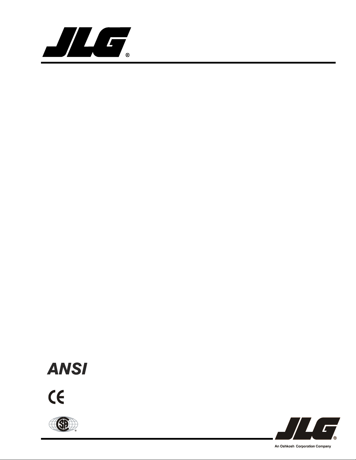
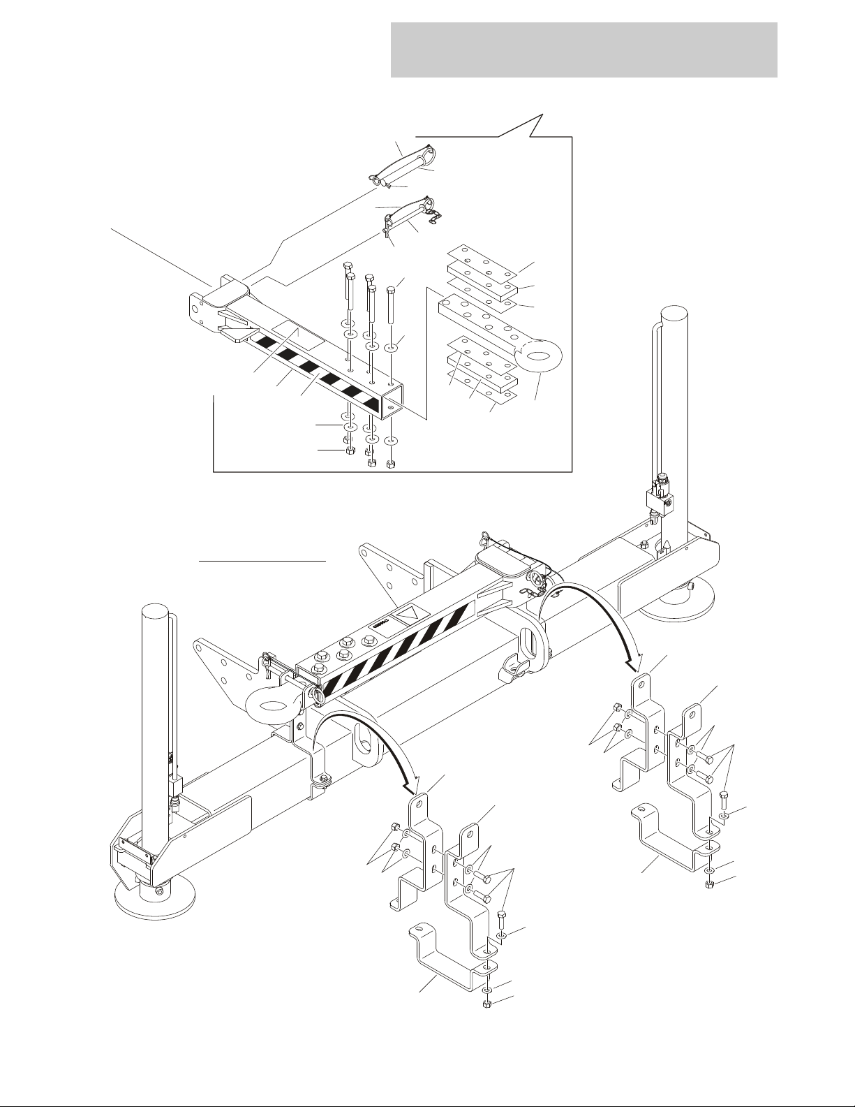
FIGURE 1-1. AXLE AND STEERING INSTALLATION WITHOUT TOW PACKAGE (SN
0200191606 TO SN 0200223954)
1-2 3394RT & 4394RT 3121250

SECTION 1 FRAME
FIGURE 1-1. AXLE AND STEERING INSTALLATION WITHOUT TOW PACKAGE (SN
0200191606 TO SN 0200223954)
ITEM # PART NUMBER QTY. DESCRIPTION REV.
1001102170 Ref OSCILLATING AXLE INSTALLATION D
1 0100011 AR Locking, Compound
2 0100019 AR Locking, Compound
3 0100038 AR Primer, Locking
4 0641822 8 Bolt 1/2in-13NC x 2-3/4in
5 0642012 1 Bolt 5/8in-11NC x 1-1/2in
6 0961950 2 Bearing
7 1684465 2 Oscillating Axle Cylinder Assembly (See CYLINDER SECTION for
Breakdown)
8 3422592 1 Pin, Axle Pivot
9 3841258 1 Keeper, Pin
10 4740158 1 Washer, Thrust
11 4891800 8 Flatwasher 1/2 Hardened
12 1001093380 1 Axle Weldment E
12A 1001100424 2 Block, Cylinder
13 4740541 2 Washer, Thrust
Ref STEERING INSTALLATIONS
1001106832 Ref Machines with Rexroth Motor & Hubs (SN 0200191606 to
SN 0200207753)
1001102242 Ref Machines with Sauer-Danfoss Motors & Fairfield Hubs
(SN 0200207753 to Present)
101 0100011 AR Locking, Compound
102 4740538 AR Thrustwasher
103 0641606 16 Bolt 3/8in-16NC x 3/4in
104 0681828 4 Bolt 1/2in-13NC x 3-1/2in (Grade 8)
105 0440291 2 Bearing
106 0962140 2 Bearing
107 1684412 1 Steer Cylinder Assembly (See CYLINDER SECTION for
Breakdown):
108 3312008 4 Nut 5/8in-11NC
109 3322201 2 Nut 3/4in-16NC
110 3423081 4 Kingpin
111 3841517 2 Rod-End with Teflon Bearing
112 3900109 4 Screw, Shoulder
113 0440271 2 Thrustwasher
114 to 115 Not Used
116 4740086 4 Washer, Thrust
117 4751800 4 Flatwasher 1/2in Wide
118 4846070 2 Tie-Rod
119 3780182 2 O-Ring
120 0440274 2 Bearing
121 4740539 AR Thrustwasher
122 4740540 AR Thrustwasher
123 4740537 AR Thrustwasher
124 3020029 AR Grease, Bearing
A
E
3121250 3394RT & 4394RT 1-3

SECTION 1 FRAME
FIGURE 1-1. AXLE AND STEERING INSTALLATION WITHOUT TOW PACKAGE (SN
0200191606 TO SN 0200223954) (CONTINUED)
ITEM # PART NUMBER QTY. DESCRIPTION REV.
125 1 Spindle Options (Left Side from Operators Position):
4130403 SN 0200191606 to SN 0200207753
4130405 SN 0200207753 to Present
126 1 Spindle Options (Right Side from Operators Position):
4130404 SN 0200191606 to SN 0200207753
4130406 SN 0200207753 to Present
Ref FRAME WELDMENTS
1001106831 Ref Frame for Machines with Rexroth Motor & Hubs (SN 0200191606
to SN 0200207753)
1001094159 Ref Frame for with Sauer-Danfoss Motors & Fairfield Hubs
(SN 0200207753 to Present)
1-4 3394RT & 4394RT 3121250

SECTION 1 FRAME
FIGURE 1-1. AXLE AND STEERING INSTALLATION WITHOUT TOW PACKAGE (SN
0200191606 TO SN 0200223954) (CONTINUED)
ITEM # PART NUMBER QTY. DESCRIPTION REV.
3121250 3394RT & 4394RT 1-5
SECTION 1 FRAME
1
2
3
11
7
7
116
118
116
120
101
106
113
117
103
102
115
109
115
101
105
101
105
110
118
112
108
118A
114
4
9
1
5
6
6810
101
105
101
111
112
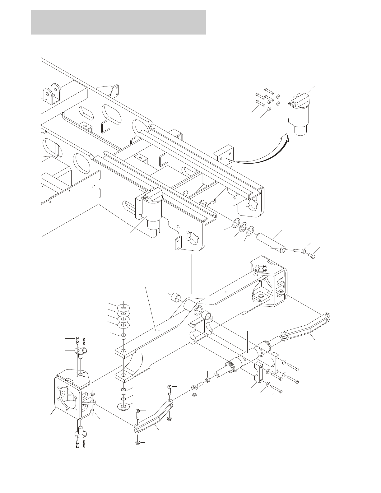
FIGURE 1-2. AXLE AND STEERING INSTALLATION WITHOUT TOW PACKAGE (SN
0200223954 TO PRESENT)
1-6 3394RT & 4394RT 3121250

SECTION 1 FRAME
FIGURE 1-2. AXLE AND STEERING INSTALLATION WITHOUT TOW PACKAGE (SN
0200223954 TO PRESENT)
ITEM # PART NUMBER QTY. DESCRIPTION REV.
1001139626 Ref OSCILLATING AXLE INSTALLATION A
1 0100011 AR Locking, Compound
2 0641822 8 Bolt 1/2in-13NC x 2-3/4in
3 0100038 AR Primer, Locking
4 1001098130 1 Axle
5 0642012 1 Bolt 5/8in-11NC x 1-1/2in
6 0961950 2 Bearing
7 1684465 2 Oscillating Axle Cylinder Assembly (See CYLINDER SECTION for
Breakdown)
8 3422592 1 Pin, Axle Pivot
9 3841258 1 Keeper, Pin
10 4740158 1 Washer, Thrust
11 4891800 8 Flatwasher 1/2 Hardened
1001139935 Ref STEERING INSTALLATION D
101 0100011 AR Locking, Compound
102 0440271 2 Thrustwasher
103 0440291 2 Bearing
104 Not Used
105 0641607 18 Bolt 3/8in-16NC x 7/8in
106 0681820 4 Bolt 1/2in-13NC x 2-1/2in (Grade 8)
107 3020029 AR Grease, Bearing
108 3312008 2 Nut 5/8in-11NC
109 3780182 2 O-Ring
110 3841520 2 Keeper
111 3900255 2 Screw, Shoulder
112 4740086 4 Washer, Thrust
113 4891800 4 Flatwasher 1/2in Hardened
114 1001116867 1 Pin, Axle Pivot
115 1001139141 4 Kingpin
116 1001139645 2 Spindle
117 1001139476 2 Bearing
118 1001139892 2 Tie-Rod
118A 1001139943 2 Bearing
119 Not Used
120 1001143434 1 Steer Cylinder Assembly (See CYLINDER SECTION for
Breakdown):
1001094159 Ref FRAME WELDMENTS
3121250 3394RT & 4394RT 1-7
SECTION 1 FRAME
205
208
209
206
202
201
203
201
207
7
12
1
3
4
7
11
13
10
13
8
9
2
5
124
101
105
119
115
6
6
128
129
130
127
104
112
101
106
116
133
126
108
116
101
106
112
103
118
102
123
136
134
121
101
113
120
114
109
109
135
109
111
12A
131
101
107
132
101
122
109
139
139
139
137
138
110
117
204
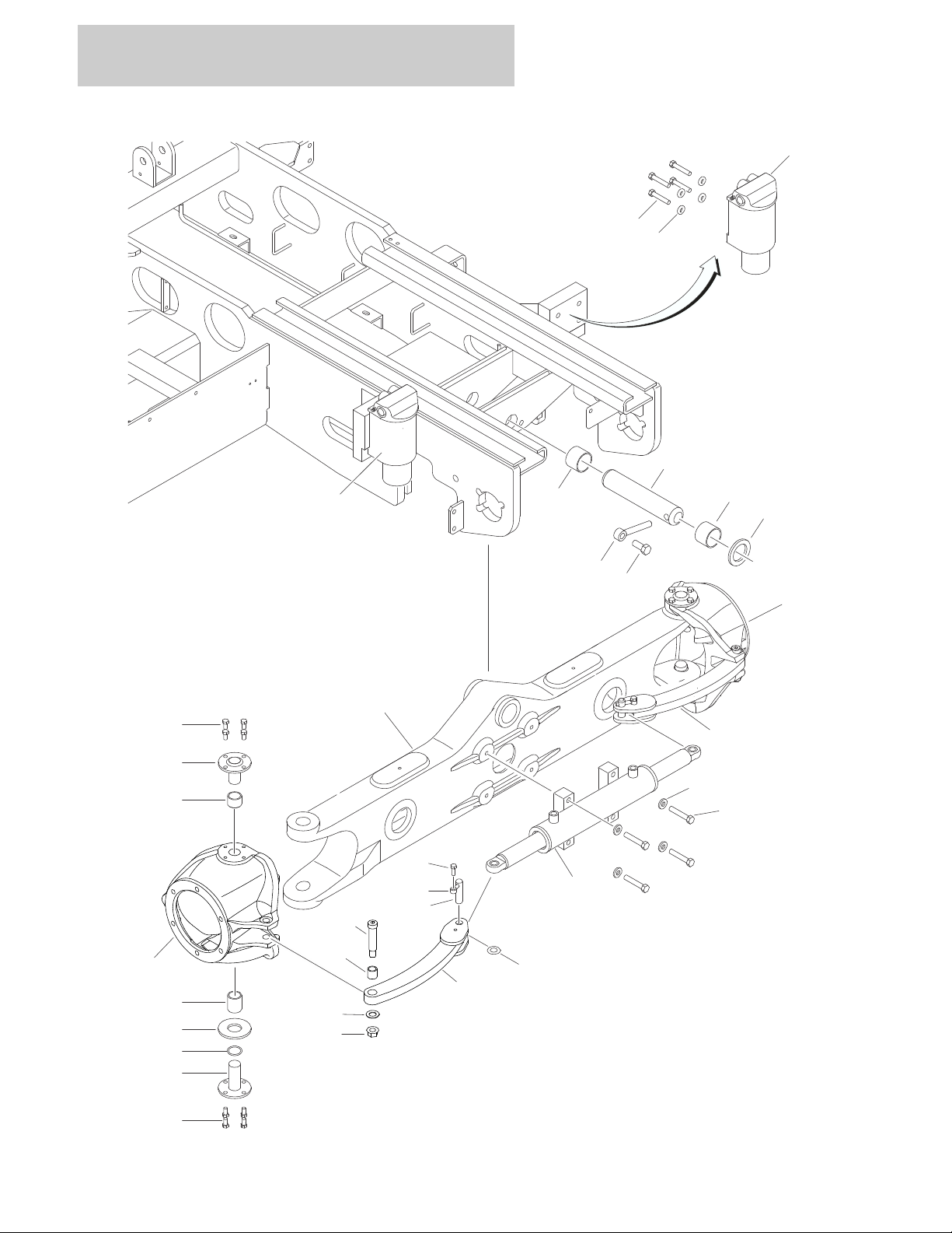
FIGURE 1-3. AXLE AND STEERING INSTALLATION WITH TOW PACKAGE
1-8 3394RT & 4394RT 3121250
SECTION 1 FRAME
CE SPEC ONLY
204
312
212
311
304
302
311
308
309
310
301
308
309
310
306
313
303
307
305
303
307
306
210
217
217
215
207
213
207
214
207
214
207
216
216
215
207
213
207
207
214
214
207
3121250 3394RT & 4394RT 1-9

SECTION 1 FRAME
FIGURE 1-3. AXLE AND STEERING INSTALLATION WITH TOW PACKAGE
ITEM # PART NUMBER QTY. DESCRIPTION REV.
1001109295 Ref OSCILLATING AXLE INSTALLATION A
1 0100011 AR Locking, Compound
2 0100019 AR Locking, Compound
3 0100038 AR Primer, Locking
4 0641822 8 Bolt 1/2in-13NC x 2-3/4in
5 0642012 1 Bolt 5/8in-11NC x 1-1/2in
6 0961950 2 Bearing
7 1684465 2 Oscillating Axle Cylinder Assembly (See CYLINDER SECTION
for Breakdown)
8 3422592 1 Pin, Axle Pivot
9 3841258 1 Keeper, Pin
10 4740158 1 Washer, Thrust
11 4891800 8 Flatwasher 1/2in Hardened
12 1001109227 1 Axle Weldment E
12A 1001100424 2 Block, Cylinder
13 4740541 2 Washer, Thrust
Ref STEERING INSTALLATIONS
1001109296 Ref ANSI Spec D
1001127658 Ref CE Spec C
101 0100019 AR Locking, Compound
102 0440271 2 Thrustwasher
103 0440274 2 Bearing
104 0440291 2 Bearing
105 0641508 1 Bolt 5/16in-18NC x 1in
106 0641606 16 Bolt 3/8in-16NC x 3/4in
107 0681828 4 Bolt 1/2in-13NC x 3-1/2in (Grade 8)
108 0962140 1 Bearing
109 0962292 5 Bearing
110 0962348 1 Bearing
111 1684412 1 Steer Cylinder Assembly (See CYLINDER SECTION for
Breakdown):
112 3020029 AR Grease, Bearing
113 3312008 3 Nut 5/8in-11NC
114 3322201 2 Nut 3/4in-16NC
115 3482848 1 Pin, Hitch
116 3423081 4 Kingpin
117 1 Plate, Hitch Pivot Options:
3574235 ANSI Spec
1001127659 CE Spec
118 3780182 2 O-Ring
119 3841143 1 Keeper, Pin
120 3841517 2 Rod-End with Teflon Bearing
121 3900109 3 Screw, Shoulder
122 3900295 1 Screw, Shoulder
123 3900296 1 Screw, Shoulder
124 4130405 1 Spindle (Left Side from Operators Position)
125 4740086 3 Thrustwasher
1-10 3394RT & 4394RT 3121250

SECTION 1 FRAME
FIGURE 1-3. AXLE AND STEERING INSTALLATION WITH TOW PACKAGE (CONTINUED)
ITEM # PART NUMBER QTY. DESCRIPTION REV.
126 4740155 2 Thrustwasher
127 4740537 AR Thrustwasher
128 4740538 AR Thrustwasher
129 4740539 AR Thrustwasher
130 4740540 AR Thrustwasher
131 4751800 4 Flatwasher 1/2in Wide
132 4846070 1 Tie-Rod (Left Side from Operators Position)
133 1001109228 1 Spindle (Right Side from Operators Position)
134 1001109229 1 Tie-Rod (Right Side from Operators Position)
135 1001109290 1 Link, Steer
136 0100011 AR Locking, Compound
137 3312201 1 Nut 3/4in-10NC
138 4712200 1 Flatwasher 3/4in Narrow
139 4740067 3 Thrustwasher
Ref TOW BAR INSTALLATION
1001110451 Ref ANSI Spec A
1001127665 Ref CE Spec A
201 0100011 AR Locking, Compound
202 0641506 2 Bolt 5/16in-18NC x 3/4in
203 0641606 2 Bolt 3/8in-16NC x 3/4in
204 3 Decal - Crushing Options:
1704578 ANSI Spec
1706960 CE Spec
205 4640261 1 Tow Valve Assembly
206 4711500 2 Flatwasher 5/16in Narrow
207 4711600 AR Flatwasher 3/8in Narrow
208 1 Decal - Towing Instruction Options:
1001110261 ANSI Spec
1001128033 CE Spec
209 1001110263 1 Bracket, Mounting
210 1001110267 1 Tow Bar Assembly (See Items 301-313 for Breakdown)
211 Not Used
212 4420051 56in/1.4m Tape, Safety
213 0641610 8 Bolt 3/8in-16NC x 1-1/4in (CE Spec Only)
214 3311605 8 Locknut 3/8in-16NC (CE Spec Only)
215 1001127701 2 Bracket, Bottom Clamp (CE Spec Only)
216 1001127702 2 Bracket, Retainer
217 1001127723 2 Bracket, Retainer
1001110267 Ref TOW BAR ASSEMBLY A
301 0360406 1 Bar, Draw
302 0682040 5 Bolt 5/8in-11NC x 5in Grade 8
303 1060584 2 Lanyard
304 3312005 5 Locknut 5/8in-11NC
305 3420352 1 Pin, Tow Hitch
306 3420372 2 Pin, Cotter
3121250 3394RT & 4394RT 1-11

SECTION 1 FRAME
FIGURE 1-3. AXLE AND STEERING INSTALLATION WITH TOW PACKAGE (CONTINUED)
ITEM # PART NUMBER QTY. DESCRIPTION REV.
307 3760170 5 Ring, Split
308 4070450 2 Shim #14 Gauge (.075)
309 4070560 2 Shim (.88)
310 4070561 2 Shim #11 Gauge
311 4752000 10 Flatwasher 5/8in Wide
312 1001110285 1 Arm, Towing
313 1001110384 1 Pin
1001094159 Ref FRAME WELDMENTS
1-12 3394RT & 4394RT 3121250

SECTION 1 FRAME
FIGURE 1-3. AXLE AND STEERING INSTALLATION WITH TOW PACKAGE (CONTINUED)
ITEM # PART NUMBER QTY. DESCRIPTION REV.
3121250 3394RT & 4394RT 1-13
SECTION 1 FRAME
6
1
2
3
4
204
203
201
205
105
106
107
5
105
113
110
SAUER-DANFOSS
& FAIRFIELD
REXROTH
109
101
103
111
104
102
112
202
OR
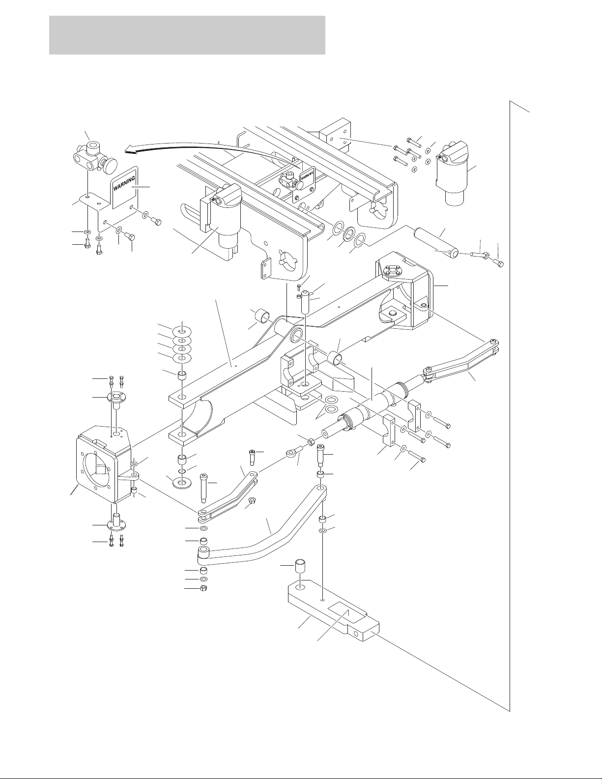
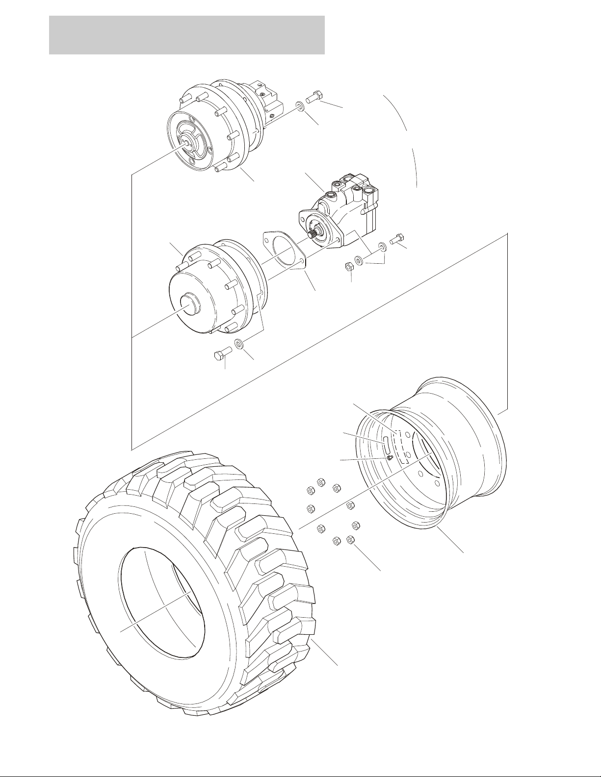
FIGURE 1-4.TIRE AND WHEEL DRIVE INSTALLATIONS
1-14 3394RT & 4394RT 3121250

SECTION 1 FRAME
FIGURE 1-4. TIRE AND WHEEL DRIVE INSTALLATIONS
ITEM # PART NUMBER QTY. DESCRIPTION REV.
Ref NOTE: DRIVE SYSTEM COMPONENTS FROM DIFFERENT
MANUFACTURERS CANNOT BE INTERCHANGED.
1001106833 Ref WHEEL DRIVE INSTALLATION (REXROTH) (SN 0200191606 TO
SN 0200207753)
1 0100019 AR Locking, Compound
2 0682012 24 Bolt 5/8in-11NC x 1-1/2in
3 2300016 AR Fluid, Hydraulic
4 2780262 4 Drive Motor/Hub Assembly (Rexroth) (See DRIVE MOTOR/HUB
ASSEMBLY (REXROTH) for Breakdown)
5 3300106 36 Lugnut
6 4892000 24 Washer, Hardened
1001102804 Ref WHEEL DRIVE INSTALLATION (SAUER-DANFOSS/FAIRFIELD)
(SN 0200207753 TO PRESENT)
101 0100011 AR Locking, Compound
102 0100019 AR Locking, Compound
103 0681810 4 Bolt 1/2in-13NC x 1-1/4in
104 0682014 24 Bolt 5/8in-11NC x 1-3/4in
105 2300016 AR Fluid, Hydraulic
106 2780267 2 Drive Hub with Brake Assembly (Rear) (Fairfield) (See DRIVE
HUB ASSEMBLIES (FAIRFIELD) for Breakdown)
107 2780268 2 Drive Hub without Brake Assembly (Front) (Fairfield) (See DRIVE
HUB ASSEMBLIES (FAIRFIELD) for Breakdown)
108 3300106 18 Lugnut
109 3311801 4 Nut 1/2in-13NC
110 3960526 4 Gasket
111 4891800 8 Flatwasher 1/2in Hardened
112 4892000 24 Flatwasher 5/8in Hardened
113 1001102805 4 Drive Motor Assembly (Sauer-Danfoss) (See DRIVE MOTOR
ASSEMBLY (SAUER-DANFOSS) for Breakdown)
114 3020008
.742gl/2.81l
Lubricant, Mobilube HD 80W-90 (23.75 oz Per Hub)
A
C
Ref TIRE AND WHEEL INSTALLATIONS
Ref 3394RT Options:
0270650 Ref 12 x 16.5 Pneumatic Non-Marking Tires B
0270653 Ref 12 x 16.5 Foam-Filled Non-Marking Tires B
0274789 Ref 31 x 15.5-15 Grass Master Tire A
0271785 Ref 33/16LL x 16.1 Foam-Filled Sand Tire A
0271718 Ref 33/16LL x 16.5 Pneumatic Lug Tire A
0271719 Ref 33/16LL x 16.5 Foam-Filled Lug Tire A
1001102190 Ref IN315/55D20 Pneumatic Lug Tire B
1001102196 Ref IN315/55D20 Foam-Filled Lug Tire B
Ref 4394RT Options:
0270653 Ref 12 x 16.5 Foam-Filled Non-Marking Tires B
0274371 Ref 12 x 16.5 Pneumatic Non-Marking Tires (Counterweight
Required)
0271785 Ref 33/16LL x 16.1 Foam-Filled Sand Tire A
A
3121250 3394RT & 4394RT 1-15

SECTION 1 FRAME
FIGURE 1-4. TIRE AND WHEEL DRIVE INSTALLATIONS (CONTINUED)
ITEM # PART NUMBER QTY. DESCRIPTION REV.
0271788 Ref 33/16LL x 16.5 Pneumatic Lug Tire A
0271719 Ref 33/16LL x 16.5 Foam-Filled Lug Tire A
1001103818 Ref IN315/55D20 Pneumatic Lug Tire (Counterweight Required) C
1001102196 Ref IN315/55D20 Foam-Filled Lug Tire A
2 12 x 16.5 Foam-Filled Right Side Non-Marking Tire
Use 1001148869 SN 0200191606 to SN 0200221363 (was p/n 0270654) B
1001148869 SN 0200221363 to Present C
2 12 x 16.5 Foam-Filled Left Side Non-Marking Tire
Use 1001148870 SN 0200191606 to SN 0200221363 (was p/n 0270655) B
1001148870 SN 0200221363 to Present C
2 12 x 16.5 Pneumatic Right Side Non-Marking Tire
Use 1001148867 SN 0200191606 to SN 0200221363 (was p/n 0270651) B
1001148867 SN 0200221363 to Present B
2 12 x 16.5 Pneumatic Left Side Non-Marking Tire
Use 1001148868 SN 0200191606 to SN 0200221363 (was p/n 0270652) B
1001148868 SN 0200221363 to Present B
4520571 4 31 x 15.5-15 Grass Master Tire B
0272268 4 33/16LL x 16.1 Foam-Filled Right Side Sand Tire C
0257755 2 33/16LL x 16.5 Pneumatic Right Side Lug Tire C
0257756 2 33/16LL x 16.5 Pneumatic Left Side Lug Tire C
0258011 2 33/16LL x 16.5 Foam-Filled Right Side Lug Tire E
0258012 2 33/16LL x 16.5 Foam-Filled Left Side Lug Tire E
1001101513 2 IN315/55D20 Pneumatic Right Side Lug Tire A
1001101512 2 IN315/55D20 Pneumatic Left Side Lug Tire A
1001102195 2 IN315/55D20 Pneumatic Right Side Lug Tire A
1001102194 2 IN315/55D20 Pneumatic Left Side Lug Tire A
Ref Note: Assemblies may require ballast/foam filling to
manufacturer’s specifications prior to installing on a
machine. Refer to Operation & Safety or Service &
Maintenance Manuals. Purchase individual tire and/or
rim only if able to foam fill tire & wheel assembly, otherwise, purchase complete assembly,
201 1 Decal Options:
1702740 Decal - 90PSI (Pneumatic Only):
1702137 Decal - 60PSI (Pneumatic Only) (Grass Master):
202 1 Tire Options:
4520240 12 x 16.5 OTR NHS Non-Marking Tire
4520576 31 x 15.5-15 Grass Tire
4520262 33/16LL x 16.1 Sand Tire
4520217 33/16LL x 16.5 Lug Tire
4520608 IN315/55D20 Lug Tire
203 1 Valve, Air Options:
4640113 With Pneumatic Tire/Wheel Assemblies
8786514 With 0258011 & 0258012 Foam-Filled Tire/Wheel
Assemblies
4640113 All Foam-Filled Tire/Wheel Assemblies except 0258011
& 0258012
1-16 3394RT & 4394RT 3121250

SECTION 1 FRAME
FIGURE 1-4. TIRE AND WHEEL DRIVE INSTALLATIONS (CONTINUED)
ITEM # PART NUMBER QTY. DESCRIPTION REV.
203 Cont’d 4641122 1 Valve, Air-Liquid (Foam-Filled Tire/Wheel Assemblies
1001148869 & 1001148870) (SN 0200221363 to
Present)
1001149953 1 Cap (Foam-Filled Tire/Wheel Assemblies 1001148869 &
1001148870) (SN 0200221363 to Present)
204 1 Rim, Wheel
4520570 15 x 13 (Use with 31 x 15.5-15 Grass Tire)
16.5 x 9.75 (Use with 12 x 16.5 Lug Tires)
Use 1001147274 SN 0200191606 to SN 0200221363 (was p/n
4860213)
1001147274 SN 0200221363 to Present
4860179 16.5 x 12 (Use with 33/16LL x 16.5 Lug Tires)
4860237 19.5 x 14 (Use with 33/16LL x 16.1 Sand Tires)
1001101511 20 x 11 (Use with IN315/55D20 Lug Tire)
205 1001105700 4 Decal - Transport Wheel Warning (IN315/55D20 Tires
Only)
3121250 3394RT & 4394RT 1-17
SECTION 1 FRAME
120 60 55 44 88 224 1 11 15 17 2 34
10
14
5
56
53
51
54
52
43
49
16
8
21
22
337330294619231220
301
302
303
304
305
27 28
FIGURE 1-5. DRIVE MOTOR/HUB ASSEMBLY (REXROTH)
1-18 3394RT & 4394RT 3121250

SECTION 1 FRAME
FIGURE 1-5. DRIVE MOTOR/HUB ASSEMBLY (REXROTH)
ITEM # PART NUMBER QTY. DESCRIPTION REV.
2780262 Ref DRIVE MOTOR/HUB ASSEMBLY (REXROTH) D
Ref Note: Unless there is capability to torque shaft (item 4) to 626
ft/lbs. (850Nm) Repair beyond this level is NOT advised.
1 Use 7022544 4 Gear, Planet
2 Use 7022545 3 Gear, Planet
3 7021325 1 Gear, Sun
4 Use 7024047 1 Nut, Shaft
Ref Note: Unless there is capability to torque shaft nut (item 4) to
626 ft/lbs. (850Nm) Repair beyond this level is NOT advised.
5 7021326 3 Pin, Planet
6 7021327 1 Ring, Support
7 7021328 1 Carrier, Planet
8 Use 7021329 1 Cover
9Not Used
10 Use 7022545 3 Bearing, Roller
11 Use 7022544 4 Bearing, Roller
12 Use 7024047 2 Bearing, Tapered Roller
13 Not Used
14 Use 7022545 3 Ring, Retaining
15 Use 7022544 4 Ring, Retaining
16 7021341 1 Ring, Retaining
17 Use 7022545 3 Disk, Support
18 Not Used
19 Use 7024047 1 O-Ring
20 Use 7024047 1 Seal, Shaft
21 Use 7021329 3 Plug, screw
22 7024048 3 Ring, Seal
23 Use 7024047 3 Bolt
24 to 26 Not Used
27 70002303 1 O-Ring
28 70002304 1 Seal
29 7024049 1 Washer, Thrust
30 7021346 1 Gear, Ring
31 to 32 Not Used
33 See Note 1 O-Ring (Note: Use Item 303 or 304)
34 Use 7021329 1 Ring, Retaining
35 to 42 Not Used
43 7021347 1 Shaft, Sun Gear
44 7024050 1 Shaft, Input
45 to 48 Not Used
49 7024051 1 Washer, Thrust
50 Not Used
51 See Note 1 Cover (Note: Use Item 304 or 305)
52 Use 7021329 1 Sleeve
53 See Note 2 Bolt (Note: Use Item 304 or 305)
54 See Note 1 O-Ring (Note: Use Item 304 or 305)
55 7024053 1 Spring
56 Use 7024054 1 Rod, Shift
3121250 3394RT & 4394RT 1-19

SECTION 1 FRAME
FIGURE 1-5. DRIVE MOTOR/HUB ASSEMBLY (REXROTH) (CONTINUED)
ITEM # PART NUMBER QTY. DESCRIPTION REV.
57 to 59 Not Used
60 Use 2780262 1 Housing, Brake
61 to 87 Not Used
88 7021344 9 Stud, Wheel
89 to 99 Not Used
100 7022552 9 Cap, Seal
101 to 119 Not Used
120 7024055 1 Motor, Hydraulic
121 to 223 Not Used
224 Use 7024047 2 Dowel, Spring Sleeve
Ref REPAIR KIT OPTIONS
301 7022544 1 Planet Gear Kit (Includes Items 1,11,15)
302 7022545 1 Planet Gear Kit (Includes Items 2,10, 14,17)
303 7024047 1 Bearing Kit (Includes Items 4,12,19,20,23,33, 224)
Ref Note: Unless there is capability to torque shaft nut (item 4) to
626 ft/lbs. (850Nm) Repair beyond this level is NOT advised.
304 7021329 1 Cover Kit (Includes Items 8,21,22,33,34,51,52,53,54)
305 7024054 1 Mechanical Disconnect Kit (Includes 51,53,54, 56)
1-20 3394RT & 4394RT 3121250

SECTION 1 FRAME
FIGURE 1-5. DRIVE MOTOR/HUB ASSEMBLY (REXROTH) (CONTINUED)
ITEM # PART NUMBER QTY. DESCRIPTION REV.
3121250 3394RT & 4394RT 1-21
SECTION 1 FRAME
3
41340
19
38
303433
3231323118
1
1
4
100
11
12
9
10
8A
13
16
15
17
14
8
7
6
2
5
5
22
20
21
23
24
25
26
28
27
37
36
35
39
29
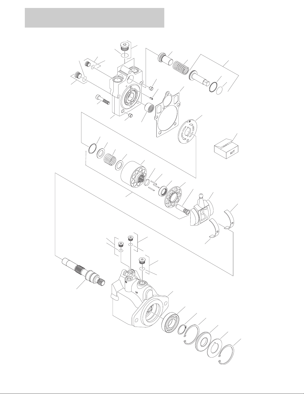
FIGURE 1-6. DRIVE MOTOR ASSEMBLY (SAUER-DANFOSS)
1-22 3394RT & 4394RT 3121250

SECTION 1 FRAME
FIGURE 1-6. DRIVE MOTOR ASSEMBLY (SAUER-DANFOSS)
ITEM # PART NUMBER QTY. DESCRIPTION REV.
1001102805 Ref DRIVE MOTOR ASSEMBLY (SAUER-DANFOSS) B
1 7022302 2 Bearing, Journal
2 7007446 1 Pin
3 7007438 2 Ring, Retaining
4 7022305 1 Swashplate
5 See Note 2 Pin (Note: Not available for purchase)
6 Use 7022328 1 Gasket
7 7024862 1 Plate, Valve
8 7023907 1 Cylinder Block Kit (Includes Items 8A & 9-17)
8A Use 7023907 1 Block, Cylinder
9 7021277 1 Guide, Slipper Retainer
10 7021275 3 Pin, Slipper Hold Down
11 Use 7023907 9 Piston Assembly
12 7021276 1 Retainer, Hold Down Pin
13 7022310 1 Retainer, Slipper
14 7022311 1 Ring, Retaining
15 7022312 1 Spring
16 7024868 1 Washer
17 7022314 1 Retainer, Spring
18 7023910 1 Shaft
19 7007439 1 Ring, Retaining
20 70000797 1 Cap, End - Axial
21 7022368 5 Screw
22 7021249 1 Bearing, Needle
23 2220886 1 Plug (Includes Item 24)
24 Use 7022328 1 O-Ring
25 2220883 1 Plug (Includes Item 26)
26 Use 7022328 1 O-Ring
27 7027419 2 Plug (Includes Item 28)
28 Use 7022328 2 O-Ring
29 7022369 1 Seat, Spring
30 70001932 1 Housing
31 2220883 2 Plug (Items Item 32)
32 Use 7022328 2 O-Ring
33 2220886 1 Plug (Items Item 34)
34 Use 7022328 1 O-Ring
35 Use 7022328 1 O-Ring
36 Use 7022328 1 Ring, Seal
37 7024854 1 Piston, Servo (Includes Items 35 & 36)
38 7007437 1 Bearing
39 7022326 1 Spring
40 Use 7022328 1 Seal, Lip
41 7022371 1 Washer, Support
— — — — — — — — — — — —
100 7022328 1 Seal Kit (Includes Items 6,24,26,28,32,34,35,36 and 40)
3121250 3394RT & 4394RT 1-23
SECTION 1 FRAME
105
105
111
110
112
121
102
119
122
123
104
103
103
101
109
107
108
28
29
114
113
116
115
118
117
120
27
141A1B1C1D1N1G1E1F
1H
1
1
17
2
7
7A
7D
7D
7C
7B
6
6B
11
200A
200B
201A
201B
201C
201D
15
8
16
3B
3F
3C
3D
3C
3B
3
3A
3E
3G
5
4
5A
6A
13
6C
6D
6G
6
6
6G
6J
6E
6F
12
1
106
106
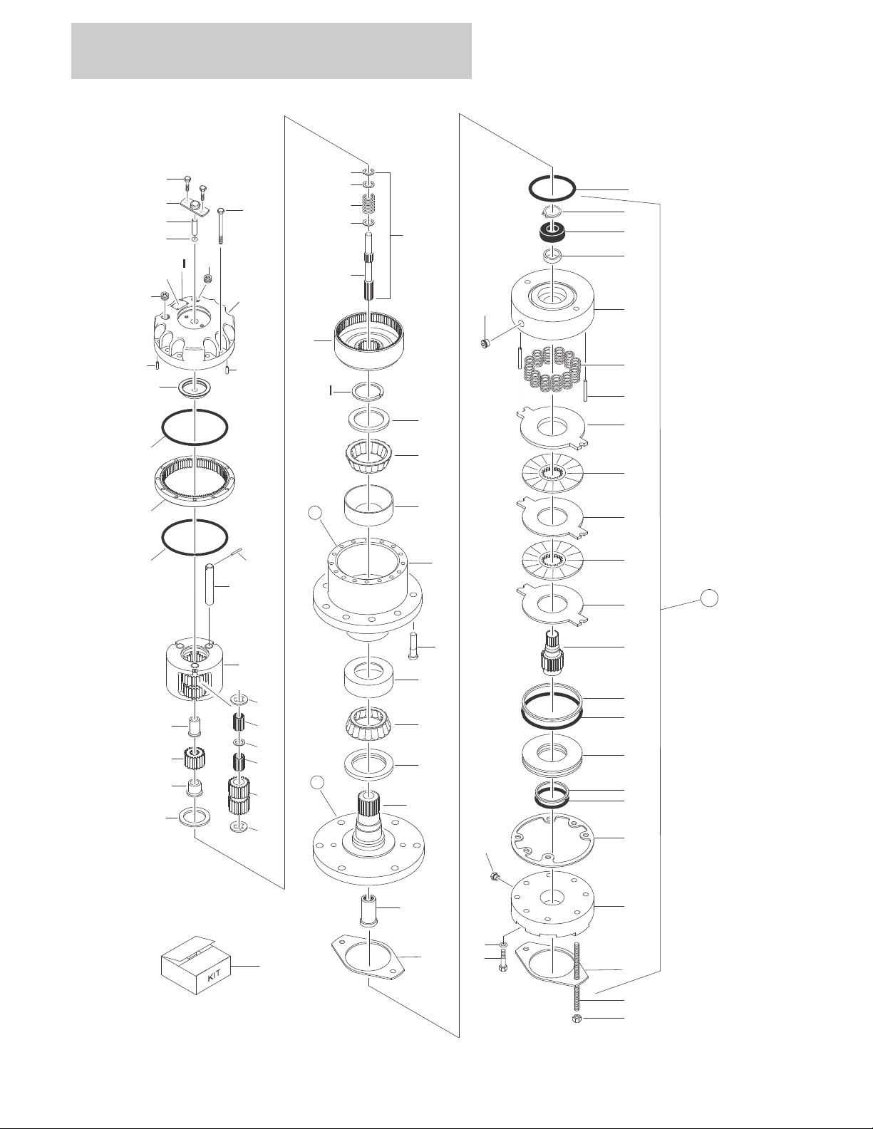
FIGURE 1-7. DRIVE HUB ASSEMBLIES (FAIRFIELD)
1-24 3394RT & 4394RT 3121250
 Loading...