

JLG 460SJ Service Manual
Service and Maintenance Manual
Models
400S
460SJ
P/N - 3120895
December 6, 2012

INTRODUCTION
SECTION A. INTRODUCTION - MAINTENANCE SAFETY PRECAUTIONS
A GENERAL
This section contains the general safety precautions
which must be observed during maintenance of the aerial
platform. It is of utmost importance that maintenance personnel pay strict attention to these warnings and precautions to avoid possible injury to themselves or others, or
damage to the equipment. A maintenance program must
be followed to ensure that the machine is safe to operate.
MODIFICATION OR ALTERATION OF AN AERIAL WORK PLATFORM
SHALL BE MADE ONLY WITH WRITTEN PERMISSION FROM THE
MANUFACTURER.
The specific precautions to be observed during maintenance are inserted at the appropriate point in the manual.
These precautions are, for the most part, those that apply
when servicing hydraulic and larger machine component
parts.
Your safety, and that of others, is the first consideration
when engaging in the maintenance of equipment. Always
be conscious of weight. Never attempt to move heavy
parts without the aid of a mechanical device. Do not allow
heavy objects to rest in an unstable position. When raising
a portion of the equipment, ensure that adequate support
is provided.
SINCE THE MACHINE MANUFACTURER HAS NO DIRECT CONTROL OVER THE FIELD INSPECTION AND MAINTENANCE, SAFETY
IN THIS AREA RESPONSIBILITY OF THE OWNER/OPERATOR.
B HYDRAULIC SYSTEM SAFETY
It should be noted that the machines hydraulic systems
operate at extremely high potentially dangerous pressures. Every effort should be made to relieve any system
pressure prior to disconnecting or removing any portion of
the system.
Relieve system pressure by cycling the applicable control
several times with the engine stopped and ignition on, to
direct any line pressure back into the reservoir. Pressure
feed lines to system components can then be disconnected with minimal fluid loss.
• ENSURE REPLACEMENT PARTS OR COMPONENTS
ARE IDENTICAL OR EQUIVALENT TO ORIGINAL PARTS
OR COMPONENTS.
• NO SMOKING IS MANDATORY. NEVER REFUEL DURING ELECTRICAL STORMS. ENSURE THAT FUEL
CAP IS CLOSED AND SECURE AT ALL OTHER
TIMES.
• REMOVE ALL RINGS, WATCHES AND JEWELRY
WHEN PERFORMING ANY MAINTENANCE.
• DO NOT WEAR LONG HAIR UNRESTRAINED, OR
LOOSE-FITTING CLOTHING AND NECKTIES WHICH
ARE APT TO BECOME CAUGHT ON OR ENTANGLED
IN EQUIPMENT.
• OBSERVE AND OBEY ALL WARNINGS AND CAUTIONS ON MACHINE AND IN SERVICEMANUAL.
• KEEP OIL, GREASE, WATER, ETC. WIPED FROM
STANDING SURFACES AND HAND HOLDS.
• USE CAUTION WHEN CHECKING A HOT, PRESSURIZED COOLANT SYSTEM.
• NEVER WORK UNDER AN ELEVATED BOOM UNTIL
BOOM HAS BEEN SAFELY RESTRAINED FROM ANY
MOVEMENT BY BLOCKING OR OVERHEAD SLING,
OR BOOM SAFETY PROP HAS BEEN ENGAGED.
• BEFORE MAKING ADJUSTMENTS, LUBRICATING OR
PERFORMING ANY OTHER MAINTENANCE, SHUT
OFF ALL POWER CONTROLS.
• BATTERY SHOULD ALWAYS BE DISCONNECTEDDURING REPLACEMENT OF ELECTRICAL COMPONENTS.
• KEEP ALL SUPPORT EQUIPMENT AND ATTACHMENTS STOWED IN THEIR PROPER PLACE.
• USE ONLY APPROVED, NONFLAMMABLE CLEANING
SOLVENTS.
CMAINTENANCE
FAILURE TO COMPLY WITH SAFETY PRECAUTIONS LISTED IN
THIS SECTION COULD RESULT IN MACHINE DAMAGE, PERSONNEL INJURY OR DEATH AND IS A SAFETY VIOLATION.
3120895 – JLG Lift – A-1

INTRODUCTION
REVISON LOG
Original Issue April 1, 2000
Revised: July 21, 2000
Revised: October 1, 2000
Revised: March 27, 2001
Revised October 1, 2001
Revised January 25,2002
Revised April 10, 2002
Revised June 14, 2004
Revised September 14, 2005
Revised October 1, 2005
Revised April 9, 2007
Revised June 20, 2007
Revised October 8, 2007
Revised December 28, 2010
Revised December 6, 2012
A-2 – JLG Lift – 3120895

TABLE OF CONTENTS
SECTION NO. TITLE PAGE NO.
SECTION A - INTRODUCTION - MAINTENANCE SAFETY PRECAUTIONS
A General . . . . . . . . . . . . . . . . . . . . . . . . . . . . . . . . . . . . . . . . . . . . . . . . . . . . . . . . . . . . . . . . . . . . . .A-1
B Hydraulic System Safety . . . . . . . . . . . . . . . . . . . . . . . . . . . . . . . . . . . . . . . . . . . . . . . . . . . . . . . . . A-1
C Maintenance . . . . . . . . . . . . . . . . . . . . . . . . . . . . . . . . . . . . . . . . . . . . . . . . . . . . . . . . . . . . . . . . . . A-1
SECTION 1 - SPECIFICATIONS
1.1 Capacities . . . . . . . . . . . . . . . . . . . . . . . . . . . . . . . . . . . . . . . . . . . . . . . . . . . . . . . . . . . . . . . . . . . .1-1
1.2 Engine Specifications . . . . . . . . . . . . . . . . . . . . . . . . . . . . . . . . . . . . . . . . . . . . . . . . . . . . . . . . . . .1-1
1.3 Tires . . . . . . . . . . . . . . . . . . . . . . . . . . . . . . . . . . . . . . . . . . . . . . . . . . . . . . . . . . . . . . . . . . . . . . . . . 1-2
1.4 Specifications and Performance Data. . . . . . . . . . . . . . . . . . . . . . . . . . . . . . . . . . . . . . . . . . . . . . .1-2
1.5 Torque Requirements . . . . . . . . . . . . . . . . . . . . . . . . . . . . . . . . . . . . . . . . . . . . . . . . . . . . . . . . . . . 1-3
1.6 Critical Stability Weights . . . . . . . . . . . . . . . . . . . . . . . . . . . . . . . . . . . . . . . . . . . . . . . . . . . . . . . . .1-3
1.7 Major Component Weights . . . . . . . . . . . . . . . . . . . . . . . . . . . . . . . . . . . . . . . . . . . . . . . . . . . . . . .1-4
1.8 Function Speeds . . . . . . . . . . . . . . . . . . . . . . . . . . . . . . . . . . . . . . . . . . . . . . . . . . . . . . . . . . . . . .1-4
1.9 Pressure Settings - PSI (Bar). . . . . . . . . . . . . . . . . . . . . . . . . . . . . . . . . . . . . . . . . . . . . . . . . . . . . .1-4
1.10 Cylinder Specifications . . . . . . . . . . . . . . . . . . . . . . . . . . . . . . . . . . . . . . . . . . . . . . . . . . . . . . . . . .1-5
1.11 Lubrication. . . . . . . . . . . . . . . . . . . . . . . . . . . . . . . . . . . . . . . . . . . . . . . . . . . . . . . . . . . . . . . . . . . .1-5
Hydraulic Oil . . . . . . . . . . . . . . . . . . . . . . . . . . . . . . . . . . . . . . . . . . . . . . . . . . . . . . . . . . . . . 1-5
1.12 Welder, Hydraulic (option) . . . . . . . . . . . . . . . . . . . . . . . . . . . . . . . . . . . . . . . . . . . . . . . . . . . . . . .1-6
1.13 Serial Number Location. . . . . . . . . . . . . . . . . . . . . . . . . . . . . . . . . . . . . . . . . . . . . . . . . . . . . . . . . .1-6
1.14 Operator Maintenance and Lubrication . . . . . . . . . . . . . . . . . . . . . . . . . . . . . . . . . . . . . . . . . . . . .1-7
Draining Oil Build Up From The Propane Regulator. . . . . . . . . . . . . . . . . . . . . . . . . . . . . . . 1-10
Propane Fuel Filter Replacement . . . . . . . . . . . . . . . . . . . . . . . . . . . . . . . . . . . . . . . . . . . . . 1-11
Propane Fuel System Pressure Relief . . . . . . . . . . . . . . . . . . . . . . . . . . . . . . . . . . . . . . . . . . 1-11
SECTION 2 - GENERAL
2.1 Machine Preparation, Inspection, and Maintenance . . . . . . . . . . . . . . . . . . . . . . . . . . . . . . . . . . .2-1
General. . . . . . . . . . . . . . . . . . . . . . . . . . . . . . . . . . . . . . . . . . . . . . . . . . . . . . . . . . . . . . . . . . 2-1
Preparation, Inspection, and Maintenance . . . . . . . . . . . . . . . . . . . . . . . . . . . . . . . . . . . . . . 2-1
Pre-Start Inspection . . . . . . . . . . . . . . . . . . . . . . . . . . . . . . . . . . . . . . . . . . . . . . . . . . . . . . . . 2-1
Pre-Delivery Inspection and Frequent Inspection . . . . . . . . . . . . . . . . . . . . . . . . . . . . . . . . . 2-1
Annual Machine Inspection . . . . . . . . . . . . . . . . . . . . . . . . . . . . . . . . . . . . . . . . . . . . . . . . . . 2-1
Preventative Maintenance . . . . . . . . . . . . . . . . . . . . . . . . . . . . . . . . . . . . . . . . . . . . . . . . . . . 2-1
2.2 Service and Guidelines . . . . . . . . . . . . . . . . . . . . . . . . . . . . . . . . . . . . . . . . . . . . . . . . . . . . . . . . . .2-2
General. . . . . . . . . . . . . . . . . . . . . . . . . . . . . . . . . . . . . . . . . . . . . . . . . . . . . . . . . . . . . . . . . . 2-2
Safety and Workmanship . . . . . . . . . . . . . . . . . . . . . . . . . . . . . . . . . . . . . . . . . . . . . . . . . . . 2-2
Cleanliness. . . . . . . . . . . . . . . . . . . . . . . . . . . . . . . . . . . . . . . . . . . . . . . . . . . . . . . . . . . . . . . 2-2
Components Removal and Installation . . . . . . . . . . . . . . . . . . . . . . . . . . . . . . . . . . . . . . . . . 2-2
Component Disassembly and Reassembly . . . . . . . . . . . . . . . . . . . . . . . . . . . . . . . . . . . . . 2-3
Pressure-Fit Parts. . . . . . . . . . . . . . . . . . . . . . . . . . . . . . . . . . . . . . . . . . . . . . . . . . . . . . . . . . 2-3
Bearings . . . . . . . . . . . . . . . . . . . . . . . . . . . . . . . . . . . . . . . . . . . . . . . . . . . . . . . . . . . . . . . . . 2-3
Gaskets . . . . . . . . . . . . . . . . . . . . . . . . . . . . . . . . . . . . . . . . . . . . . . . . . . . . . . . . . . . . . . . . . 2-3
Bolt Usage and Torque Application . . . . . . . . . . . . . . . . . . . . . . . . . . . . . . . . . . . . . . . . . . . 2-3
Hydraulic Lines and Electrical Wiring . . . . . . . . . . . . . . . . . . . . . . . . . . . . . . . . . . . . . . . . . . 2-3
Hydraulic System. . . . . . . . . . . . . . . . . . . . . . . . . . . . . . . . . . . . . . . . . . . . . . . . . . . . . . . . . . 2-3
Lubrication . . . . . . . . . . . . . . . . . . . . . . . . . . . . . . . . . . . . . . . . . . . . . . . . . . . . . . . . . . . . . . . 2-3
Battery . . . . . . . . . . . . . . . . . . . . . . . . . . . . . . . . . . . . . . . . . . . . . . . . . . . . . . . . . . . . . . . . . . 2-3
Lubrication and Servicing . . . . . . . . . . . . . . . . . . . . . . . . . . . . . . . . . . . . . . . . . . . . . . . . . . . 2-3
3120895 – JLG Lift – i

TABLE OF CONTENTS
SECTION NO. TITLE PAGE NO.
2.3 Lubrication and Information . . . . . . . . . . . . . . . . . . . . . . . . . . . . . . . . . . . . . . . . . . . . . . . . . . . . . . 2-3
Hydraulic System. . . . . . . . . . . . . . . . . . . . . . . . . . . . . . . . . . . . . . . . . . . . . . . . . . . . . . . . . . 2-3
Hydraulic Oil . . . . . . . . . . . . . . . . . . . . . . . . . . . . . . . . . . . . . . . . . . . . . . . . . . . . . . . . . . . . . 2-4
Changing Hydraulic Oil . . . . . . . . . . . . . . . . . . . . . . . . . . . . . . . . . . . . . . . . . . . . . . . . . . . . . 2-4
Lubrication Specifications . . . . . . . . . . . . . . . . . . . . . . . . . . . . . . . . . . . . . . . . . . . . . . . . . . . 2-4
2.4 Cylinder Drift Test . . . . . . . . . . . . . . . . . . . . . . . . . . . . . . . . . . . . . . . . . . . . . . . . . . . . . . . . . . . . . .2-4
Platform Drift . . . . . . . . . . . . . . . . . . . . . . . . . . . . . . . . . . . . . . . . . . . . . . . . . . . . . . . . . . . . . 2-4
Cylinder Drift . . . . . . . . . . . . . . . . . . . . . . . . . . . . . . . . . . . . . . . . . . . . . . . . . . . . . . . . . . . . . 2-4
2.5 Pins and Composite Bearing Repair Guidelines . . . . . . . . . . . . . . . . . . . . . . . . . . . . . . . . . . . . . .2-5
2.6 Welding on JLG Equipment . . . . . . . . . . . . . . . . . . . . . . . . . . . . . . . . . . . . . . . . . . . . . . . . . . . . . . 2-5
Do the Following When Welding on JLG Equipment . . . . . . . . . . . . . . . . . . . . . . . . . . . . . . 2-5
Do NOT Do the Following When Welding on JLG Equipment . . . . . . . . . . . . . . . . . . . . . . . 2-5
SECTION 3 - CHASSIS & TURNTABLE
3.1 Tires & Wheels. . . . . . . . . . . . . . . . . . . . . . . . . . . . . . . . . . . . . . . . . . . . . . . . . . . . . . . . . . . . . . . . . 3-1
Tire Inflation . . . . . . . . . . . . . . . . . . . . . . . . . . . . . . . . . . . . . . . . . . . . . . . . . . . . . . . . . . . . . . 3-1
Tire Damage . . . . . . . . . . . . . . . . . . . . . . . . . . . . . . . . . . . . . . . . . . . . . . . . . . . . . . . . . . . . . 3-1
Tire Replacement. . . . . . . . . . . . . . . . . . . . . . . . . . . . . . . . . . . . . . . . . . . . . . . . . . . . . . . . . . 3-1
Wheel Replacement. . . . . . . . . . . . . . . . . . . . . . . . . . . . . . . . . . . . . . . . . . . . . . . . . . . . . . . . 3-1
Wheel Installation. . . . . . . . . . . . . . . . . . . . . . . . . . . . . . . . . . . . . . . . . . . . . . . . . . . . . . . . . . 3-1
3.2 Drive Hub Part No. 2780243 (2wd Rear) Part No. 2780244 (4wd Rear) . . . . . . . . . . . . . . . . . . . .3-2
Disassembly. . . . . . . . . . . . . . . . . . . . . . . . . . . . . . . . . . . . . . . . . . . . . . . . . . . . . . . . . . . . . . 3-2
Disassembly of Cover Unit (8). . . . . . . . . . . . . . . . . . . . . . . . . . . . . . . . . . . . . . . . . . . . . . . . 3-3
Disassembly of First Stage Planetary Assembly. . . . . . . . . . . . . . . . . . . . . . . . . . . . . . . . . . 3-3
Disassembly of the Second Stage Planet Gears (1). . . . . . . . . . . . . . . . . . . . . . . . . . . . . . . 3-3
Assembly of First Stage Planetary Assembly (7) . . . . . . . . . . . . . . . . . . . . . . . . . . . . . . . . . 3-3
Assembly Of End Cover Unit (8) . . . . . . . . . . . . . . . . . . . . . . . . . . . . . . . . . . . . . . . . . . . . . . 3-3
Final Assembly. . . . . . . . . . . . . . . . . . . . . . . . . . . . . . . . . . . . . . . . . . . . . . . . . . . . . . . . . . . . 3-3
3.3 Drive Hub Part No. 2780246 (4wd steer axle Prior to S/N 0300076633) . . . . . . . . . . . . . . . . . . . .3-5
Disassembly. . . . . . . . . . . . . . . . . . . . . . . . . . . . . . . . . . . . . . . . . . . . . . . . . . . . . . . . . . . . . . 3-5
Disassembly of Cover Unit (8). . . . . . . . . . . . . . . . . . . . . . . . . . . . . . . . . . . . . . . . . . . . . . . . 3-5
Disassembly of First Stage Planetary Assembly. . . . . . . . . . . . . . . . . . . . . . . . . . . . . . . . . . 3-5
Disassembly of the Second Stage Planet Gears (1). . . . . . . . . . . . . . . . . . . . . . . . . . . . . . . 3-5
Assembly of First Stage Planetary Assembly (7) . . . . . . . . . . . . . . . . . . . . . . . . . . . . . . . . . 3-6
Assembly of End Cover Unit (8) . . . . . . . . . . . . . . . . . . . . . . . . . . . . . . . . . . . . . . . . . . . . . . 3-6
Final Assembly. . . . . . . . . . . . . . . . . . . . . . . . . . . . . . . . . . . . . . . . . . . . . . . . . . . . . . . . . . . . 3-6
3.4 Torque Hub - 4WD (Machines built after S/N 0300076633) . . . . . . . . . . . . . . . . . . . . . . . . . . . . . . 3-8
Roll and Leak Testing . . . . . . . . . . . . . . . . . . . . . . . . . . . . . . . . . . . . . . . . . . . . . . . . . . . . . . 3-8
Tightening and Torquing Bolts . . . . . . . . . . . . . . . . . . . . . . . . . . . . . . . . . . . . . . . . . . . . . . . 3-8
Oil Information . . . . . . . . . . . . . . . . . . . . . . . . . . . . . . . . . . . . . . . . . . . . . . . . . . . . . . . . . . . . 3-8
Main Disassembly for ”B” Drives. . . . . . . . . . . . . . . . . . . . . . . . . . . . . . . . . . . . . . . . . . . . . . 3-8
Hub-Spindle Disassembly . . . . . . . . . . . . . . . . . . . . . . . . . . . . . . . . . . . . . . . . . . . . . . . . . . . 3-9
Cover Disassembly . . . . . . . . . . . . . . . . . . . . . . . . . . . . . . . . . . . . . . . . . . . . . . . . . . . . . . . . 3-9
Carrier Disassembly. . . . . . . . . . . . . . . . . . . . . . . . . . . . . . . . . . . . . . . . . . . . . . . . . . . . . . . . 3-9
Assembly of the Carrier . . . . . . . . . . . . . . . . . . . . . . . . . . . . . . . . . . . . . . . . . . . . . . . . . . . . . 3-10
Cover Sub-Assembly . . . . . . . . . . . . . . . . . . . . . . . . . . . . . . . . . . . . . . . . . . . . . . . . . . . . . . . 3-12
Hub-Spindle Sub-Assembly . . . . . . . . . . . . . . . . . . . . . . . . . . . . . . . . . . . . . . . . . . . . . . . . . 3-13
Main Assembly. . . . . . . . . . . . . . . . . . . . . . . . . . . . . . . . . . . . . . . . . . . . . . . . . . . . . . . . . . . . 3-15
Tool List . . . . . . . . . . . . . . . . . . . . . . . . . . . . . . . . . . . . . . . . . . . . . . . . . . . . . . . . . . . . . . . . . 3-20
3.5 Re-Aligning Torque Hub Input Coupling . . . . . . . . . . . . . . . . . . . . . . . . . . . . . . . . . . . . . . . . . . . .3-21
Equipment Required . . . . . . . . . . . . . . . . . . . . . . . . . . . . . . . . . . . . . . . . . . . . . . . . . . . . . . . 3-21
Procedure . . . . . . . . . . . . . . . . . . . . . . . . . . . . . . . . . . . . . . . . . . . . . . . . . . . . . . . . . . . . . . . 3-21
ii – JLG Lift – 3120895

TABLE OF CONTENTS
SECTION NO. TITLE PAGE NO.
3.6 Drive Brake . . . . . . . . . . . . . . . . . . . . . . . . . . . . . . . . . . . . . . . . . . . . . . . . . . . . . . . . . . . . . . . . . . .3-22
Pre-Installation Checks . . . . . . . . . . . . . . . . . . . . . . . . . . . . . . . . . . . . . . . . . . . . . . . . . . . . . 3-22
Installation . . . . . . . . . . . . . . . . . . . . . . . . . . . . . . . . . . . . . . . . . . . . . . . . . . . . . . . . . . . . . . . 3-23
Maintenance . . . . . . . . . . . . . . . . . . . . . . . . . . . . . . . . . . . . . . . . . . . . . . . . . . . . . . . . . . . . . 3-23
Disassembly. . . . . . . . . . . . . . . . . . . . . . . . . . . . . . . . . . . . . . . . . . . . . . . . . . . . . . . . . . . . . . 3-23
Examination . . . . . . . . . . . . . . . . . . . . . . . . . . . . . . . . . . . . . . . . . . . . . . . . . . . . . . . . . . . . . . 3-23
Assembly . . . . . . . . . . . . . . . . . . . . . . . . . . . . . . . . . . . . . . . . . . . . . . . . . . . . . . . . . . . . . . . . 3-23
3.7 Drive Motor . . . . . . . . . . . . . . . . . . . . . . . . . . . . . . . . . . . . . . . . . . . . . . . . . . . . . . . . . . . . . . . . . . .3-25
Description. . . . . . . . . . . . . . . . . . . . . . . . . . . . . . . . . . . . . . . . . . . . . . . . . . . . . . . . . . . . . . . 3-25
Shaft Seal Replacement . . . . . . . . . . . . . . . . . . . . . . . . . . . . . . . . . . . . . . . . . . . . . . . . . . . . 3-25
Loop Flushing Valve . . . . . . . . . . . . . . . . . . . . . . . . . . . . . . . . . . . . . . . . . . . . . . . . . . . . . . . 3-26
Troubleshooting. . . . . . . . . . . . . . . . . . . . . . . . . . . . . . . . . . . . . . . . . . . . . . . . . . . . . . . . . . . 3-27
Disassembly. . . . . . . . . . . . . . . . . . . . . . . . . . . . . . . . . . . . . . . . . . . . . . . . . . . . . . . . . . . . . . 3-28
Inspection . . . . . . . . . . . . . . . . . . . . . . . . . . . . . . . . . . . . . . . . . . . . . . . . . . . . . . . . . . . . . . . 3-32
Assembly . . . . . . . . . . . . . . . . . . . . . . . . . . . . . . . . . . . . . . . . . . . . . . . . . . . . . . . . . . . . . . . . 3-34
Initial Start-up Procedures . . . . . . . . . . . . . . . . . . . . . . . . . . . . . . . . . . . . . . . . . . . . . . . . . . . 3-39
3.8 Adjustment Procedure For Lockout Valve . . . . . . . . . . . . . . . . . . . . . . . . . . . . . . . . . . . . . . . . . . .3-40
3.9 Toe-In Adjustment . . . . . . . . . . . . . . . . . . . . . . . . . . . . . . . . . . . . . . . . . . . . . . . . . . . . . . . . . . . . . .3-40
3.10 2WD Hub . . . . . . . . . . . . . . . . . . . . . . . . . . . . . . . . . . . . . . . . . . . . . . . . . . . . . . . . . . . . . . . . . . . . .3-41
Removal & Disassembly . . . . . . . . . . . . . . . . . . . . . . . . . . . . . . . . . . . . . . . . . . . . . . . . . . . . 3-41
Cleaning & Inspection . . . . . . . . . . . . . . . . . . . . . . . . . . . . . . . . . . . . . . . . . . . . . . . . . . . . . . 3-41
Assembly & Installation . . . . . . . . . . . . . . . . . . . . . . . . . . . . . . . . . . . . . . . . . . . . . . . . . . . . . 3-42
3.11 Oscillating Axle Bleeding Procedure. . . . . . . . . . . . . . . . . . . . . . . . . . . . . . . . . . . . . . . . . . . . . . . .3-43
3.12 Oscillating Axle Lockout Test . . . . . . . . . . . . . . . . . . . . . . . . . . . . . . . . . . . . . . . . . . . . . . . . . . . . . 3-43
3.13 Swing Bearing . . . . . . . . . . . . . . . . . . . . . . . . . . . . . . . . . . . . . . . . . . . . . . . . . . . . . . . . . . . . . . . . .3-44
Turntable Bearing Mounting Bolt Condition Check . . . . . . . . . . . . . . . . . . . . . . . . . . . . . . . 3-44
Wear Tolerance . . . . . . . . . . . . . . . . . . . . . . . . . . . . . . . . . . . . . . . . . . . . . . . . . . . . . . . . . . . 3-45
Replacement of Swing Bearing . . . . . . . . . . . . . . . . . . . . . . . . . . . . . . . . . . . . . . . . . . . . . . . 3-46
Swing Bearing Torque Value. . . . . . . . . . . . . . . . . . . . . . . . . . . . . . . . . . . . . . . . . . . . . . . . . 3-47
Swing Drive Installation . . . . . . . . . . . . . . . . . . . . . . . . . . . . . . . . . . . . . . . . . . . . . . . . . . . . . 3-47
3.14 Swing Brake (Prior to S/N 64802) . . . . . . . . . . . . . . . . . . . . . . . . . . . . . . . . . . . . . . . . . . . . . . . . . .3-50
Installation . . . . . . . . . . . . . . . . . . . . . . . . . . . . . . . . . . . . . . . . . . . . . . . . . . . . . . . . . . . . . . . 3-50
Brake Disassembly . . . . . . . . . . . . . . . . . . . . . . . . . . . . . . . . . . . . . . . . . . . . . . . . . . . . . . . . 3-50
Assembly Information . . . . . . . . . . . . . . . . . . . . . . . . . . . . . . . . . . . . . . . . . . . . . . . . . . . . . . 3-50
3.15 Swing Brake S/N 64802 to Present. . . . . . . . . . . . . . . . . . . . . . . . . . . . . . . . . . . . . . . . . . . . . . . . .3-52
Disassembly. . . . . . . . . . . . . . . . . . . . . . . . . . . . . . . . . . . . . . . . . . . . . . . . . . . . . . . . . . . . . . 3-52
Assembly . . . . . . . . . . . . . . . . . . . . . . . . . . . . . . . . . . . . . . . . . . . . . . . . . . . . . . . . . . . . . . . . 3-52
3.16 Swing Drive Torque Hub . . . . . . . . . . . . . . . . . . . . . . . . . . . . . . . . . . . . . . . . . . . . . . . . . . . . . . . . . 3-54
Disassembly Procedure. . . . . . . . . . . . . . . . . . . . . . . . . . . . . . . . . . . . . . . . . . . . . . . . . . . . . 3-54
Hub Shaft Sub-Assembly Procedure . . . . . . . . . . . . . . . . . . . . . . . . . . . . . . . . . . . . . . . . . . 3-58
Carrier Sub-Assembly Procedure . . . . . . . . . . . . . . . . . . . . . . . . . . . . . . . . . . . . . . . . . . . . . 3-60
3.17 Semi-Track . . . . . . . . . . . . . . . . . . . . . . . . . . . . . . . . . . . . . . . . . . . . . . . . . . . . . . . . . . . . . . . . . . .3-61
Testing the Track . . . . . . . . . . . . . . . . . . . . . . . . . . . . . . . . . . . . . . . . . . . . . . . . . . . . . . . . . . 3-61
Removing the Track . . . . . . . . . . . . . . . . . . . . . . . . . . . . . . . . . . . . . . . . . . . . . . . . . . . . . . . 3-62
Assuming Normal Wear. . . . . . . . . . . . . . . . . . . . . . . . . . . . . . . . . . . . . . . . . . . . . . . . . . . . . 3-62
Adjustment. . . . . . . . . . . . . . . . . . . . . . . . . . . . . . . . . . . . . . . . . . . . . . . . . . . . . . . . . . . . . . . 3-62
3.18 Generator. . . . . . . . . . . . . . . . . . . . . . . . . . . . . . . . . . . . . . . . . . . . . . . . . . . . . . . . . . . . . . . . . . . . . 3-66
Every 250 hours . . . . . . . . . . . . . . . . . . . . . . . . . . . . . . . . . . . . . . . . . . . . . . . . . . . . . . . . . . . 3-66
Every 500 hours . . . . . . . . . . . . . . . . . . . . . . . . . . . . . . . . . . . . . . . . . . . . . . . . . . . . . . . . . . . 3-66
Overload Protection. . . . . . . . . . . . . . . . . . . . . . . . . . . . . . . . . . . . . . . . . . . . . . . . . . . . . . . . 3-66
Inspecting Brushes, Replacing Brushes, and Cleaning Slip Rings . . . . . . . . . . . . . . . . . . . 3-66
3120895 – JLG Lift – iii

TABLE OF CONTENTS
SECTION NO. TITLE PAGE NO.
3.19 Ford EFI Engine . . . . . . . . . . . . . . . . . . . . . . . . . . . . . . . . . . . . . . . . . . . . . . . . . . . . . . . . . . . . . . .3-68
Performing Diagnostics . . . . . . . . . . . . . . . . . . . . . . . . . . . . . . . . . . . . . . . . . . . . . . . . . . . . . 3-68
Visual/Physical Engine Inspection Check . . . . . . . . . . . . . . . . . . . . . . . . . . . . . . . . . . . . . . . 3-68
EFI Diagnostics (Prior to S/N 61718) . . . . . . . . . . . . . . . . . . . . . . . . . . . . . . . . . . . . . . . . . . 3-68
ECM and Sensors . . . . . . . . . . . . . . . . . . . . . . . . . . . . . . . . . . . . . . . . . . . . . . . . . . . . . . . . . 3-69
Fuel System . . . . . . . . . . . . . . . . . . . . . . . . . . . . . . . . . . . . . . . . . . . . . . . . . . . . . . . . . . . . . . 3-75
3.20 Throttle Checks and Adjustments - Deutz Engine (Prior to S/N 61718) . . . . . . . . . . . . . . . . . . . .3-79
General . . . . . . . . . . . . . . . . . . . . . . . . . . . . . . . . . . . . . . . . . . . . . . . . . . . . . . . . . . . . . . . . . 3-79
Procedure . . . . . . . . . . . . . . . . . . . . . . . . . . . . . . . . . . . . . . . . . . . . . . . . . . . . . . . . . . . . . . . 3-80
Controller Status . . . . . . . . . . . . . . . . . . . . . . . . . . . . . . . . . . . . . . . . . . . . . . . . . . . . . . . . . . 3-80
Failure Modes . . . . . . . . . . . . . . . . . . . . . . . . . . . . . . . . . . . . . . . . . . . . . . . . . . . . . . . . . . . . 3-80
3.21 Tilt Alarm Switch (Prior to S/N 61718) . . . . . . . . . . . . . . . . . . . . . . . . . . . . . . . . . . . . . . . . . . . . . . 3-83
Manual Adjustment . . . . . . . . . . . . . . . . . . . . . . . . . . . . . . . . . . . . . . . . . . . . . . . . . . . . . . . . 3-83
3.22 Hydraulic Welder (225-4) . . . . . . . . . . . . . . . . . . . . . . . . . . . . . . . . . . . . . . . . . . . . . . . . . . . . . . . .3-86
Replacement of Weld Transformer . . . . . . . . . . . . . . . . . . . . . . . . . . . . . . . . . . . . . . . . . . . . 3-86
Replacement of Hydraulic Motor. . . . . . . . . . . . . . . . . . . . . . . . . . . . . . . . . . . . . . . . . . . . . . 3-86
Replacement of Fine Control. . . . . . . . . . . . . . . . . . . . . . . . . . . . . . . . . . . . . . . . . . . . . . . . . 3-86
Rotor Replacement . . . . . . . . . . . . . . . . . . . . . . . . . . . . . . . . . . . . . . . . . . . . . . . . . . . . . . . . 3-87
Replacement of Flow Regulator . . . . . . . . . . . . . . . . . . . . . . . . . . . . . . . . . . . . . . . . . . . . . . 3-87
Replacement of Exciting Rectifier Bridge . . . . . . . . . . . . . . . . . . . . . . . . . . . . . . . . . . . . . . . 3-87
Replacement of Weld Rectifier Bridge . . . . . . . . . . . . . . . . . . . . . . . . . . . . . . . . . . . . . . . . . 3-88
Replace Brushes on Sky Welder. . . . . . . . . . . . . . . . . . . . . . . . . . . . . . . . . . . . . . . . . . . . . . 3-88
Replacing Range Switch . . . . . . . . . . . . . . . . . . . . . . . . . . . . . . . . . . . . . . . . . . . . . . . . . . . . 3-88
Replacing Selector Switch. . . . . . . . . . . . . . . . . . . . . . . . . . . . . . . . . . . . . . . . . . . . . . . . . . . 3-88
Replacement of Couplings . . . . . . . . . . . . . . . . . . . . . . . . . . . . . . . . . . . . . . . . . . . . . . . . . . 3-89
Voltage Change Over - 120/240 Volt. . . . . . . . . . . . . . . . . . . . . . . . . . . . . . . . . . . . . . . . . . . 3-89
3.23 Troubleshooting of the Sky Welder . . . . . . . . . . . . . . . . . . . . . . . . . . . . . . . . . . . . . . . . . . . . . . . .3-90
Low Sky Welder Speed . . . . . . . . . . . . . . . . . . . . . . . . . . . . . . . . . . . . . . . . . . . . . . . . . . . . . 3-90
Low Welding Amps . . . . . . . . . . . . . . . . . . . . . . . . . . . . . . . . . . . . . . . . . . . . . . . . . . . . . . . . 3-90
No Output on Weld Receptacles or AC Receptacles . . . . . . . . . . . . . . . . . . . . . . . . . . . . . . 3-90
No Ac Output but Weld Output . . . . . . . . . . . . . . . . . . . . . . . . . . . . . . . . . . . . . . . . . . . . . . . 3-90
No Output on Weld Receptacle but AC Receptacle Output OK. . . . . . . . . . . . . . . . . . . . . . 3-94
Welder Completely Dead - No AC or Weld Power . . . . . . . . . . . . . . . . . . . . . . . . . . . . . . . . 3-94
Intermittent Welder Operation . . . . . . . . . . . . . . . . . . . . . . . . . . . . . . . . . . . . . . . . . . . . . . . . 3-94
3.24 Deutz EMR 2 (S/N 77682 to Present) . . . . . . . . . . . . . . . . . . . . . . . . . . . . . . . . . . . . . . . . . . . . . . . 3-95
3.25 GM Engine General Maintenance. . . . . . . . . . . . . . . . . . . . . . . . . . . . . . . . . . . . . . . . . . . . . . . . . .3-108
Maintenance of the Drive Belt . . . . . . . . . . . . . . . . . . . . . . . . . . . . . . . . . . . . . . . . . . . . . . . . 3-108
Engine Electrical System Maintenance. . . . . . . . . . . . . . . . . . . . . . . . . . . . . . . . . . . . . . . . . 3-108
Checking/Filling Engine Oil Level . . . . . . . . . . . . . . . . . . . . . . . . . . . . . . . . . . . . . . . . . . . . . 3-108
Changing The Engine Oil . . . . . . . . . . . . . . . . . . . . . . . . . . . . . . . . . . . . . . . . . . . . . . . . . . . 3-109
Coolant Fill Procedure - Dual Fuel Engine . . . . . . . . . . . . . . . . . . . . . . . . . . . . . . . . . . . . . . 3-109
3.26 GM Engine Dual Fuel System . . . . . . . . . . . . . . . . . . . . . . . . . . . . . . . . . . . . . . . . . . . . . . . . . . . .3-111
Fuel Filter . . . . . . . . . . . . . . . . . . . . . . . . . . . . . . . . . . . . . . . . . . . . . . . . . . . . . . . . . . . . . . . . 3-111
Electric Lock Off. . . . . . . . . . . . . . . . . . . . . . . . . . . . . . . . . . . . . . . . . . . . . . . . . . . . . . . . . . . 3-111
EPR Assembly . . . . . . . . . . . . . . . . . . . . . . . . . . . . . . . . . . . . . . . . . . . . . . . . . . . . . . . . . . . . 3-112
Low Pressure Regulator (LPR) . . . . . . . . . . . . . . . . . . . . . . . . . . . . . . . . . . . . . . . . . . . . . . . 3-112
Air Fuel Mixer . . . . . . . . . . . . . . . . . . . . . . . . . . . . . . . . . . . . . . . . . . . . . . . . . . . . . . . . . . . . . 3-113
Electronic Throttle Control (ETC) . . . . . . . . . . . . . . . . . . . . . . . . . . . . . . . . . . . . . . . . . . . . . 3-113
Engine Control Module . . . . . . . . . . . . . . . . . . . . . . . . . . . . . . . . . . . . . . . . . . . . . . . . . . . . . 3-114
Heated Exhaust Gas Oxygen Sensor . . . . . . . . . . . . . . . . . . . . . . . . . . . . . . . . . . . . . . . . . . 3-114
Gasoline Multi Point Fuel Injection System (MPFI) . . . . . . . . . . . . . . . . . . . . . . . . . . . . . . . . 3-114
Gasoline Fuel Pump . . . . . . . . . . . . . . . . . . . . . . . . . . . . . . . . . . . . . . . . . . . . . . . . . . . . . . . 3-115
Gasoline Pressure And Temperature Sensor Manifold. . . . . . . . . . . . . . . . . . . . . . . . . . . . . 3-115
Fuel Filter . . . . . . . . . . . . . . . . . . . . . . . . . . . . . . . . . . . . . . . . . . . . . . . . . . . . . . . . . . . . . . . . 3-115
Fuel Injector Rail . . . . . . . . . . . . . . . . . . . . . . . . . . . . . . . . . . . . . . . . . . . . . . . . . . . . . . . . . . 3-115
Fuel Injector . . . . . . . . . . . . . . . . . . . . . . . . . . . . . . . . . . . . . . . . . . . . . . . . . . . . . . . . . . . . . . 3-115
iv – JLG Lift – 3120895

TABLE OF CONTENTS
SECTION NO. TITLE PAGE NO.
3.27 GM Engine Fuel System Repair . . . . . . . . . . . . . . . . . . . . . . . . . . . . . . . . . . . . . . . . . . . . . . . . . . .3-116
Propane Fuel System Pressure Relief . . . . . . . . . . . . . . . . . . . . . . . . . . . . . . . . . . . . . . . . . . 3-116
Propane Fuel System Leak Test . . . . . . . . . . . . . . . . . . . . . . . . . . . . . . . . . . . . . . . . . . . . . . 3-116
Propane Fuel Filter Replacement . . . . . . . . . . . . . . . . . . . . . . . . . . . . . . . . . . . . . . . . . . . . . 3-116
Electronic Pressure Regulator (EPR) Assembly Replacement. . . . . . . . . . . . . . . . . . . . . . . 3-117
Temperature Manifold Absolute Pressure (TMAP) Sensor . . . . . . . . . . . . . . . . . . . . . . . . . . 3-118
Electronic Throttle Control Replacement . . . . . . . . . . . . . . . . . . . . . . . . . . . . . . . . . . . . . . . 3-119
MIXER REPLACEMENT . . . . . . . . . . . . . . . . . . . . . . . . . . . . . . . . . . . . . . . . . . . . . . . . . . . . . 3-120
Coolant Hose Replacement. . . . . . . . . . . . . . . . . . . . . . . . . . . . . . . . . . . . . . . . . . . . . . . . . . 3-120
Vapor Hose Replacement. . . . . . . . . . . . . . . . . . . . . . . . . . . . . . . . . . . . . . . . . . . . . . . . . . . 3-120
Engine Control Module Replacement . . . . . . . . . . . . . . . . . . . . . . . . . . . . . . . . . . . . . . . . . . 3-121
Heated Exhaust Gas Oxygen Sensor Replacement . . . . . . . . . . . . . . . . . . . . . . . . . . . . . . . 3-121
3.28 GM Engine LPG Fuel System Diagnosis . . . . . . . . . . . . . . . . . . . . . . . . . . . . . . . . . . . . . . . . . . . .3-121
Fuel System Description . . . . . . . . . . . . . . . . . . . . . . . . . . . . . . . . . . . . . . . . . . . . . . . . . . . . 3-121
Diagnostic Aids . . . . . . . . . . . . . . . . . . . . . . . . . . . . . . . . . . . . . . . . . . . . . . . . . . . . . . . . . . . 3-122
3.29 Perkins Engine General Maintenance. . . . . . . . . . . . . . . . . . . . . . . . . . . . . . . . . . . . . . . . . . . . . . . 3-138
Replacing the Engine Crankcase Breather . . . . . . . . . . . . . . . . . . . . . . . . . . . . . . . . . . . . . . 3-138
Engine Oil Level - Check . . . . . . . . . . . . . . . . . . . . . . . . . . . . . . . . . . . . . . . . . . . . . . . . . . . . 3-138
Engine Oil and Filter - Change . . . . . . . . . . . . . . . . . . . . . . . . . . . . . . . . . . . . . . . . . . . . . . . 3-138
Fuel Filter/Water Separator . . . . . . . . . . . . . . . . . . . . . . . . . . . . . . . . . . . . . . . . . . . . . . . . . . 3-140
Setting the Actuator . . . . . . . . . . . . . . . . . . . . . . . . . . . . . . . . . . . . . . . . . . . . . . . . . . . . . . . . 3-141
Speed Sensor Installation . . . . . . . . . . . . . . . . . . . . . . . . . . . . . . . . . . . . . . . . . . . . . . . . . . . 3-142
3.30 Engine Radiator Fill Procedure - Perkins & Caterpillar. . . . . . . . . . . . . . . . . . . . . . . . . . . . . . . . . .3-142
3.31 DGC DIAGNOSTIC SUPPORT AND TROUBLE CODE DEFINITIONS . . . . . . . . . . . . . . . . . . . . . .3-144
Section Layout . . . . . . . . . . . . . . . . . . . . . . . . . . . . . . . . . . . . . . . . . . . . . . . . . . . . . . . . . . . . 3-144
List of Abbreviations in this Section. . . . . . . . . . . . . . . . . . . . . . . . . . . . . . . . . . . . . . . . . . . . 3-145
Fault Code Broadcast . . . . . . . . . . . . . . . . . . . . . . . . . . . . . . . . . . . . . . . . . . . . . . . . . . . . . . 3-146
Diagnostic Trouble Codes . . . . . . . . . . . . . . . . . . . . . . . . . . . . . . . . . . . . . . . . . . . . . . . . . . . 3-146
CAN . . . . . . . . . . . . . . . . . . . . . . . . . . . . . . . . . . . . . . . . . . . . . . . . . . . . . . . . . . . . . . . . . . . . 3-146
MIL Output . . . . . . . . . . . . . . . . . . . . . . . . . . . . . . . . . . . . . . . . . . . . . . . . . . . . . . . . . . . . . . . 3-147
Diagnostic Calibration Configuration and Corrective Actions . . . . . . . . . . . . . . . . . . . . . . . 3-147
Fault/Diagnostic Trouble Code Interaction . . . . . . . . . . . . . . . . . . . . . . . . . . . . . . . . . . . . . . 3-148
DBW Diagnostic Test. . . . . . . . . . . . . . . . . . . . . . . . . . . . . . . . . . . . . . . . . . . . . . . . . . . . . . . 3-153
3.32 Diagnostic Trouble Code Fault Descriptions . . . . . . . . . . . . . . . . . . . . . . . . . . . . . . . . . . . . . . . . .3-154
DTC 116- ECT Higher Than Expected Stage 1 . . . . . . . . . . . . . . . . . . . . . . . . . . . . . . . . . . . 3-154
DTC 117- ECT/CHT Low Voltage . . . . . . . . . . . . . . . . . . . . . . . . . . . . . . . . . . . . . . . . . . . . . 3-155
DTC 118- ECT/CHT High Voltage . . . . . . . . . . . . . . . . . . . . . . . . . . . . . . . . . . . . . . . . . . . . . 3-157
DTC 122- TPS1 Signal Voltage Low . . . . . . . . . . . . . . . . . . . . . . . . . . . . . . . . . . . . . . . . . . . 3-159
DTC 123- TPS1 Signal Voltage High . . . . . . . . . . . . . . . . . . . . . . . . . . . . . . . . . . . . . . . . . . . 3-162
DTC 217- ECT Higher Than Expected 2 . . . . . . . . . . . . . . . . . . . . . . . . . . . . . . . . . . . . . . . . 3-164
DTC 219- RPM Higher Than Max Allowed Governed Speed . . . . . . . . . . . . . . . . . . . . . . . . 3-165
DTC 336- Crank Signal Input Noise . . . . . . . . . . . . . . . . . . . . . . . . . . . . . . . . . . . . . . . . . . . 3-166
DTC 337- Loss of Crank Input Signal . . . . . . . . . . . . . . . . . . . . . . . . . . . . . . . . . . . . . . . . . . 3-168
DTC 521- Oil Pressure Sender/Switch High Pressure . . . . . . . . . . . . . . . . . . . . . . . . . . . . . 3-169
DTC 524- Oil Pressure Low . . . . . . . . . . . . . . . . . . . . . . . . . . . . . . . . . . . . . . . . . . . . . . . . . . 3-172
DTC 562- Battery Voltage (VBat) Low . . . . . . . . . . . . . . . . . . . . . . . . . . . . . . . . . . . . . . . . . . 3-176
DTC 563- Battery Voltage (VBat) High . . . . . . . . . . . . . . . . . . . . . . . . . . . . . . . . . . . . . . . . . 3-178
DTC 601- Microprocessor Failure - FLASH . . . . . . . . . . . . . . . . . . . . . . . . . . . . . . . . . . . . . . 3-180
DTC 604- Microprocessor Failure - RAM. . . . . . . . . . . . . . . . . . . . . . . . . . . . . . . . . . . . . . . . 3-182
3120895 – JLG Lift – v

TABLE OF CONTENTS
SECTION NO. TITLE PAGE NO.
DTC 606- Microprocessor Failure - COP. . . . . . . . . . . . . . . . . . . . . . . . . . . . . . . . . . . . . . . . 3-184
DTC 642- 5 Volt External Low Voltage . . . . . . . . . . . . . . . . . . . . . . . . . . . . . . . . . . . . . . . . . 3-186
DTC 643- 5 Volt External High Voltage . . . . . . . . . . . . . . . . . . . . . . . . . . . . . . . . . . . . . . . . . 3-188
DTC 1612- Microprocessor Failure - RTI 1 . . . . . . . . . . . . . . . . . . . . . . . . . . . . . . . . . . . . . . 3-190
DTC 1613- Microprocessor Failure - RTI 2 . . . . . . . . . . . . . . . . . . . . . . . . . . . . . . . . . . . . . . 3-191
DTC 1614- Microprocessor Failure - RTI 3 . . . . . . . . . . . . . . . . . . . . . . . . . . . . . . . . . . . . . . 3-193
DTC 1615- Microprocessor Failure - A/D . . . . . . . . . . . . . . . . . . . . . . . . . . . . . . . . . . . . . . . 3-195
DTC 1616- Microprocessor Failure - interrupt. . . . . . . . . . . . . . . . . . . . . . . . . . . . . . . . . . . . 3-197
DTC 1625- CAN J1939 Shutdown Request . . . . . . . . . . . . . . . . . . . . . . . . . . . . . . . . . . . . . 3-199
DTC 1626- CAN J1939 Transmit (Tx) Fault . . . . . . . . . . . . . . . . . . . . . . . . . . . . . . . . . . . . . . 3-200
DTC 1627- CAN J1939 Receive (Rx) Fault . . . . . . . . . . . . . . . . . . . . . . . . . . . . . . . . . . . . . . 3-201
DTC 1628- CAN Address Conflict Failure . . . . . . . . . . . . . . . . . . . . . . . . . . . . . . . . . . . . . . . 3-202
DTC 1629- J1939 TSC1 Message Reciept Loss . . . . . . . . . . . . . . . . . . . . . . . . . . . . . . . . . . 3-204
DTC 1652- TPS1 Loss of Communications. . . . . . . . . . . . . . . . . . . . . . . . . . . . . . . . . . . . . . 3-205
DTC 2111- Unable to Reach Lower TPS . . . . . . . . . . . . . . . . . . . . . . . . . . . . . . . . . . . . . . . . 3-206
DTC 2112- Unable to Reach Higher TPS . . . . . . . . . . . . . . . . . . . . . . . . . . . . . . . . . . . . . . . 3-208
DTC 9999- Throttle Actuator Failsafe Spring Failure. . . . . . . . . . . . . . . . . . . . . . . . . . . . . . . 3-209
DTC to SPN/FMI Table . . . . . . . . . . . . . . . . . . . . . . . . . . . . . . . . . . . . . . . . . . . . . . . . . . . . . 3-210
SECTION 4 - BOOM & PLATFORM
4.1 Boom . . . . . . . . . . . . . . . . . . . . . . . . . . . . . . . . . . . . . . . . . . . . . . . . . . . . . . . . . . . . . . . . . . . . . . . .4-1
Removal . . . . . . . . . . . . . . . . . . . . . . . . . . . . . . . . . . . . . . . . . . . . . . . . . . . . . . . . . . . . . . . . . 4-1
Disassembly. . . . . . . . . . . . . . . . . . . . . . . . . . . . . . . . . . . . . . . . . . . . . . . . . . . . . . . . . . . . . . 4-2
Inspection . . . . . . . . . . . . . . . . . . . . . . . . . . . . . . . . . . . . . . . . . . . . . . . . . . . . . . . . . . . . . . . 4-3
Assembly . . . . . . . . . . . . . . . . . . . . . . . . . . . . . . . . . . . . . . . . . . . . . . . . . . . . . . . . . . . . . . . . 4-4
Installation . . . . . . . . . . . . . . . . . . . . . . . . . . . . . . . . . . . . . . . . . . . . . . . . . . . . . . . . . . . . . . . 4-5
4.2 Articulating jib . . . . . . . . . . . . . . . . . . . . . . . . . . . . . . . . . . . . . . . . . . . . . . . . . . . . . . . . . . . . . . . . .4-6
Removal . . . . . . . . . . . . . . . . . . . . . . . . . . . . . . . . . . . . . . . . . . . . . . . . . . . . . . . . . . . . . . . . . 4-6
4.3 Limit Switch Adjustments . . . . . . . . . . . . . . . . . . . . . . . . . . . . . . . . . . . . . . . . . . . . . . . . . . . . . . . . 4-6
Boom Horizontal Limit Switch . . . . . . . . . . . . . . . . . . . . . . . . . . . . . . . . . . . . . . . . . . . . . . . . 4-6
Dual Capacity Angle Limit Switch . . . . . . . . . . . . . . . . . . . . . . . . . . . . . . . . . . . . . . . . . . . . . 4-6
Boom Length Limit Switch. . . . . . . . . . . . . . . . . . . . . . . . . . . . . . . . . . . . . . . . . . . . . . . . . . . 4-6
4.4 Drive Card Setup Procedures . . . . . . . . . . . . . . . . . . . . . . . . . . . . . . . . . . . . . . . . . . . . . . . . . . . . .4-10
Machine Orientation When Doing Speed Tests . . . . . . . . . . . . . . . . . . . . . . . . . . . . . . . . . . 4-10
Test Notes . . . . . . . . . . . . . . . . . . . . . . . . . . . . . . . . . . . . . . . . . . . . . . . . . . . . . . . . . . . . . . . 4-10
Lift, Swing, and Drive Cards . . . . . . . . . . . . . . . . . . . . . . . . . . . . . . . . . . . . . . . . . . . . . . . . . 4-11
Flow Control Card . . . . . . . . . . . . . . . . . . . . . . . . . . . . . . . . . . . . . . . . . . . . . . . . . . . . . . . . . 4-11
4.5 Helac Rotary actuator . . . . . . . . . . . . . . . . . . . . . . . . . . . . . . . . . . . . . . . . . . . . . . . . . . . . . . . . . . . 4-13
Theory Of Operation . . . . . . . . . . . . . . . . . . . . . . . . . . . . . . . . . . . . . . . . . . . . . . . . . . . . . . . 4-13
Tools Required for Assembly/Disassembly . . . . . . . . . . . . . . . . . . . . . . . . . . . . . . . . . . . . . 4-16
Disassembly. . . . . . . . . . . . . . . . . . . . . . . . . . . . . . . . . . . . . . . . . . . . . . . . . . . . . . . . . . . . . . 4-16
Inspection . . . . . . . . . . . . . . . . . . . . . . . . . . . . . . . . . . . . . . . . . . . . . . . . . . . . . . . . . . . . . . . 4-20
Assembly . . . . . . . . . . . . . . . . . . . . . . . . . . . . . . . . . . . . . . . . . . . . . . . . . . . . . . . . . . . . . . . . 4-20
Installing Counterbalance Valve . . . . . . . . . . . . . . . . . . . . . . . . . . . . . . . . . . . . . . . . . . . . . . 4-23
vi – JLG Lift – 3120895

TABLE OF CONTENTS
SECTION NO. TITLE PAGE NO.
SECTION 5 - HYDRAULICS
5.1 Cylinders - Theory of Operation . . . . . . . . . . . . . . . . . . . . . . . . . . . . . . . . . . . . . . . . . . . . . . . . . . .5-1
Systems Incorporating Double Acting Cylinders . . . . . . . . . . . . . . . . . . . . . . . . . . . . . . . . . 5-1
Systems Incorporating Holding Valves . . . . . . . . . . . . . . . . . . . . . . . . . . . . . . . . . . . . . . . . . 5-1
5.2 Cylinder Repair . . . . . . . . . . . . . . . . . . . . . . . . . . . . . . . . . . . . . . . . . . . . . . . . . . . . . . . . . . . . . . . .5-1
Cylinders Without Counterbalance Valves . . . . . . . . . . . . . . . . . . . . . . . . . . . . . . . . . . . . . . 5-1
Cylinders With Dual Counterbalance Valves. . . . . . . . . . . . . . . . . . . . . . . . . . . . . . . . . . . . . 5-1
Disassembly. . . . . . . . . . . . . . . . . . . . . . . . . . . . . . . . . . . . . . . . . . . . . . . . . . . . . . . . . . . . . . 5-2
Cleaning and Inspection . . . . . . . . . . . . . . . . . . . . . . . . . . . . . . . . . . . . . . . . . . . . . . . . . . . . 5-3
Assembly . . . . . . . . . . . . . . . . . . . . . . . . . . . . . . . . . . . . . . . . . . . . . . . . . . . . . . . . . . . . . . . . 5-4
5.3 Valves - Theory of Operation. . . . . . . . . . . . . . . . . . . . . . . . . . . . . . . . . . . . . . . . . . . . . . . . . . . . . .5-14
Solenoid Control Valve . . . . . . . . . . . . . . . . . . . . . . . . . . . . . . . . . . . . . . . . . . . . . . . . . . . . . 5-14
Relief Valves. . . . . . . . . . . . . . . . . . . . . . . . . . . . . . . . . . . . . . . . . . . . . . . . . . . . . . . . . . . . . . 5-17
5.4 Pressure Setting Procedures . . . . . . . . . . . . . . . . . . . . . . . . . . . . . . . . . . . . . . . . . . . . . . . . . . . . .5-17
1. Bang-Bang Main Relief Valve; . . . . . . . . . . . . . . . . . . . . . . . . . . . . . . . . . . . . . . . . . . . . . . 5-17
2. Steer; . . . . . . . . . . . . . . . . . . . . . . . . . . . . . . . . . . . . . . . . . . . . . . . . . . . . . . . . . . . . . . . . . 5-17
3. Platform Level Up; . . . . . . . . . . . . . . . . . . . . . . . . . . . . . . . . . . . . . . . . . . . . . . . . . . . . . . . 5-17
4. Platform Level Down;. . . . . . . . . . . . . . . . . . . . . . . . . . . . . . . . . . . . . . . . . . . . . . . . . . . . . 5-17
5. Articulating Jib Up; . . . . . . . . . . . . . . . . . . . . . . . . . . . . . . . . . . . . . . . . . . . . . . . . . . . . . . 5-17
6. Articulating Jib Down; . . . . . . . . . . . . . . . . . . . . . . . . . . . . . . . . . . . . . . . . . . . . . . . . . . . . 5-18
7. The Bang-Bang Main Relief Valve; . . . . . . . . . . . . . . . . . . . . . . . . . . . . . . . . . . . . . . . . . . 5-18
8. The Proportional Main relief valve; . . . . . . . . . . . . . . . . . . . . . . . . . . . . . . . . . . . . . . . . . . 5-18
9. Lift Down; . . . . . . . . . . . . . . . . . . . . . . . . . . . . . . . . . . . . . . . . . . . . . . . . . . . . . . . . . . . . . . 5-18
10. Swing; . . . . . . . . . . . . . . . . . . . . . . . . . . . . . . . . . . . . . . . . . . . . . . . . . . . . . . . . . . . . . . . 5-18
5.5 Hydraulic Motor Repair (H Series Char-lynn) . . . . . . . . . . . . . . . . . . . . . . . . . . . . . . . . . . . . . . . . .5-18
Disassembly. . . . . . . . . . . . . . . . . . . . . . . . . . . . . . . . . . . . . . . . . . . . . . . . . . . . . . . . . . . . . . 5-18
Reassembly Shaft End . . . . . . . . . . . . . . . . . . . . . . . . . . . . . . . . . . . . . . . . . . . . . . . . . . . . . 5-20
Gerotor End . . . . . . . . . . . . . . . . . . . . . . . . . . . . . . . . . . . . . . . . . . . . . . . . . . . . . . . . . . . . . . 5-22
Timing Procedure . . . . . . . . . . . . . . . . . . . . . . . . . . . . . . . . . . . . . . . . . . . . . . . . . . . . . . . . . 5-23
Standard Rotation . . . . . . . . . . . . . . . . . . . . . . . . . . . . . . . . . . . . . . . . . . . . . . . . . . . . . . . . . 5-23
Reverse Rotation . . . . . . . . . . . . . . . . . . . . . . . . . . . . . . . . . . . . . . . . . . . . . . . . . . . . . . . . . . 5-23
5.6 Hydraulic Pump “Neutral” Or Null Adjustment . . . . . . . . . . . . . . . . . . . . . . . . . . . . . . . . . . . . . . . .5-26
5.7 Non-feedback, Proportional Electrical Control - NFPE. . . . . . . . . . . . . . . . . . . . . . . . . . . . . . . . . . 5-26
Features and Benefits of the NFPE Control . . . . . . . . . . . . . . . . . . . . . . . . . . . . . . . . . . . . . 5-26
Input Signal requirements . . . . . . . . . . . . . . . . . . . . . . . . . . . . . . . . . . . . . . . . . . . . . . . . . . . 5-26
5.8 Hydraulic Component Start-Up Procedures and Recommendations . . . . . . . . . . . . . . . . . . . . . .5-27
SECTION 6 - JLG CONTROL SYSTEM (S/N 61718 TO PRESENT)
6.1 Introduction . . . . . . . . . . . . . . . . . . . . . . . . . . . . . . . . . . . . . . . . . . . . . . . . . . . . . . . . . . . . . . . . . . .6-1
6.2 To Connect the JLG Control System Analyzer . . . . . . . . . . . . . . . . . . . . . . . . . . . . . . . . . . . . . . . . 6-3
6.3 Using the Analyzer . . . . . . . . . . . . . . . . . . . . . . . . . . . . . . . . . . . . . . . . . . . . . . . . . . . . . . . . . . . . .6-3
6.4 Changing the Access Level of the Hand Held Analyzer . . . . . . . . . . . . . . . . . . . . . . . . . . . . . . . . .6-5
6.5 Adjusting Parameters Using the Hand Held Analyzer . . . . . . . . . . . . . . . . . . . . . . . . . . . . . . . . . . 6-7
6.6 Machine Setup . . . . . . . . . . . . . . . . . . . . . . . . . . . . . . . . . . . . . . . . . . . . . . . . . . . . . . . . . . . . . . . .6-8
6.7 Level Vehicle Description . . . . . . . . . . . . . . . . . . . . . . . . . . . . . . . . . . . . . . . . . . . . . . . . . . . . . . . .6-8
6.8 Machine Personality Settings . . . . . . . . . . . . . . . . . . . . . . . . . . . . . . . . . . . . . . . . . . . . . . . . . . . . .6-17
6.9 System Test. . . . . . . . . . . . . . . . . . . . . . . . . . . . . . . . . . . . . . . . . . . . . . . . . . . . . . . . . . . . . . . . . . .6-62
Test from the Platform . . . . . . . . . . . . . . . . . . . . . . . . . . . . . . . . . . . . . . . . . . . . . . . . . . . . . . 6-62
Test from the Ground Station . . . . . . . . . . . . . . . . . . . . . . . . . . . . . . . . . . . . . . . . . . . . . . . . 6-64
6.10 Analyzer Diagnostics Menu Structure. . . . . . . . . . . . . . . . . . . . . . . . . . . . . . . . . . . . . . . . . . . . . . .6-81
3120895 – JLG Lift – vii

TABLE OF CONTENTS
SECTION NO. TITLE PAGE NO.
SECTION 7 - BASIC ELECTRICAL INFORMATION & SCHEMATICS
7.1 General . . . . . . . . . . . . . . . . . . . . . . . . . . . . . . . . . . . . . . . . . . . . . . . . . . . . . . . . . . . . . . . . . . . . . . 7-1
7.2 Multimeter Basics . . . . . . . . . . . . . . . . . . . . . . . . . . . . . . . . . . . . . . . . . . . . . . . . . . . . . . . . . . . . . . 7-1
Grounding . . . . . . . . . . . . . . . . . . . . . . . . . . . . . . . . . . . . . . . . . . . . . . . . . . . . . . . . . . . . . . . 7-1
Backprobing . . . . . . . . . . . . . . . . . . . . . . . . . . . . . . . . . . . . . . . . . . . . . . . . . . . . . . . . . . . . . 7-1
Min/Max . . . . . . . . . . . . . . . . . . . . . . . . . . . . . . . . . . . . . . . . . . . . . . . . . . . . . . . . . . . . . . . . . 7-1
Polarity . . . . . . . . . . . . . . . . . . . . . . . . . . . . . . . . . . . . . . . . . . . . . . . . . . . . . . . . . . . . . . . . . . 7-1
Scale . . . . . . . . . . . . . . . . . . . . . . . . . . . . . . . . . . . . . . . . . . . . . . . . . . . . . . . . . . . . . . . . . . . 7-1
Voltage Measurement . . . . . . . . . . . . . . . . . . . . . . . . . . . . . . . . . . . . . . . . . . . . . . . . . . . . . . 7-1
Resistance Measurement . . . . . . . . . . . . . . . . . . . . . . . . . . . . . . . . . . . . . . . . . . . . . . . . . . . 7-2
Continuity Measurement . . . . . . . . . . . . . . . . . . . . . . . . . . . . . . . . . . . . . . . . . . . . . . . . . . . . 7-2
Current Measurement . . . . . . . . . . . . . . . . . . . . . . . . . . . . . . . . . . . . . . . . . . . . . . . . . . . . . . 7-3
7.3 Checking Switches . . . . . . . . . . . . . . . . . . . . . . . . . . . . . . . . . . . . . . . . . . . . . . . . . . . . . . . . . . . . .7-3
Basic Check. . . . . . . . . . . . . . . . . . . . . . . . . . . . . . . . . . . . . . . . . . . . . . . . . . . . . . . . . . . . . . 7-3
Limit Switches . . . . . . . . . . . . . . . . . . . . . . . . . . . . . . . . . . . . . . . . . . . . . . . . . . . . . . . . . . . . 7-3
Automatic Switches . . . . . . . . . . . . . . . . . . . . . . . . . . . . . . . . . . . . . . . . . . . . . . . . . . . . . . . . 7-4
Switch Wiring - Low Side, High Side . . . . . . . . . . . . . . . . . . . . . . . . . . . . . . . . . . . . . . . . . . . 7-4
7.4 Applying Silicone Dielectric Compound to Electrical Connections . . . . . . . . . . . . . . . . . . . . . . . .7-4
Installation of Dielectric Grease. . . . . . . . . . . . . . . . . . . . . . . . . . . . . . . . . . . . . . . . . . . . . . . 7-5
Deutsch HD, DT, DTM, DRC Series . . . . . . . . . . . . . . . . . . . . . . . . . . . . . . . . . . . . . . . . . . . 7-5
AMP Seal . . . . . . . . . . . . . . . . . . . . . . . . . . . . . . . . . . . . . . . . . . . . . . . . . . . . . . . . . . . . . . . . 7-5
AMP Mate-N-Lok . . . . . . . . . . . . . . . . . . . . . . . . . . . . . . . . . . . . . . . . . . . . . . . . . . . . . . . . . . 7-6
DIN Connectors . . . . . . . . . . . . . . . . . . . . . . . . . . . . . . . . . . . . . . . . . . . . . . . . . . . . . . . . . . . 7-6
Exclusions . . . . . . . . . . . . . . . . . . . . . . . . . . . . . . . . . . . . . . . . . . . . . . . . . . . . . . . . . . . . . . . 7-6
7.5 AMP Connector . . . . . . . . . . . . . . . . . . . . . . . . . . . . . . . . . . . . . . . . . . . . . . . . . . . . . . . . . . . . . . . .7-8
Applying Silicone Dielectric Compound to AMP Connectors. . . . . . . . . . . . . . . . . . . . . . . . 7-8
Assembly . . . . . . . . . . . . . . . . . . . . . . . . . . . . . . . . . . . . . . . . . . . . . . . . . . . . . . . . . . . . . . . . 7-8
Disassembly. . . . . . . . . . . . . . . . . . . . . . . . . . . . . . . . . . . . . . . . . . . . . . . . . . . . . . . . . . . . . . 7-10
Wedge Lock. . . . . . . . . . . . . . . . . . . . . . . . . . . . . . . . . . . . . . . . . . . . . . . . . . . . . . . . . . . . . . 7-10
Service - Voltage Reading . . . . . . . . . . . . . . . . . . . . . . . . . . . . . . . . . . . . . . . . . . . . . . . . . . . 7-10
7.6 Deutsch Connectors . . . . . . . . . . . . . . . . . . . . . . . . . . . . . . . . . . . . . . . . . . . . . . . . . . . . . . . . . . . .7-12
DT/DTP Series Assembly. . . . . . . . . . . . . . . . . . . . . . . . . . . . . . . . . . . . . . . . . . . . . . . . . . . . 7-12
DT/DTP Series Disassembly . . . . . . . . . . . . . . . . . . . . . . . . . . . . . . . . . . . . . . . . . . . . . . . . . 7-12
HD30/HDP20 Series Assembly . . . . . . . . . . . . . . . . . . . . . . . . . . . . . . . . . . . . . . . . . . . . . . . 7-13
HD30/HDP20 Series Disassembly. . . . . . . . . . . . . . . . . . . . . . . . . . . . . . . . . . . . . . . . . . . . . 7-13
viii – JLG Lift – 3120895

LIST OF FIGURES
FIGURE NO. TITLE PAGE NO.
1-1. Serial Number Location. . . . . . . . . . . . . . . . . . . . . . . . . . . . . . . . . . . . . . . . . . . . . . . . . . . . . . . . . .1-6
1-2. Operator Maintenance and Lubrication Diagram . . . . . . . . . . . . . . . . . . . . . . . . . . . . . . . . . . . . . . 1-6
1-3. Deutz Engine Dipstick . . . . . . . . . . . . . . . . . . . . . . . . . . . . . . . . . . . . . . . . . . . . . . . . . . . . . . . . . . .1-8
1-4. Filter Lock Assembly . . . . . . . . . . . . . . . . . . . . . . . . . . . . . . . . . . . . . . . . . . . . . . . . . . . . . . . . . . . .1-11
1-5. Torque Chart (SAE Fasteners - Sheet 1 of 7) . . . . . . . . . . . . . . . . . . . . . . . . . . . . . . . . . . . . . . . . .1-12
1-6. Torque Chart (SAE Fasteners - Sheet 2 of 7) . . . . . . . . . . . . . . . . . . . . . . . . . . . . . . . . . . . . . . . . .1-13
1-7. Torque Chart (SAE Fasteners - Sheet 3 of 7) . . . . . . . . . . . . . . . . . . . . . . . . . . . . . . . . . . . . . . . . .1-14
1-8. Torque Chart (SAE Fasteners - Sheet 4 of 7) . . . . . . . . . . . . . . . . . . . . . . . . . . . . . . . . . . . . . . . . .1-15
1-9. Torque Chart (METRIC Fasteners - Sheet 5 of 7) . . . . . . . . . . . . . . . . . . . . . . . . . . . . . . . . . . . . . . 1-16
1-10. Torque Chart (METRIC Fasteners - Sheet 6 of 7). . . . . . . . . . . . . . . . . . . . . . . . . . . . . . . . . . . . . .1-17
1-11. Torque Chart (METRIC Fasteners - Sheet 7 of 7). . . . . . . . . . . . . . . . . . . . . . . . . . . . . . . . . . . . . .1-18
2-1. Engine Operating Temperature Specifications - Deutz . . . . . . . . . . . . . . . . . . . . . . . . . . . . . . . . .2-9
2-2. Engine Operating Temperature Specifications - Ford . . . . . . . . . . . . . . . . . . . . . . . . . . . . . . . . . . 2-10
2-3. Engine Operating Temperature Specifications - Caterpillar. . . . . . . . . . . . . . . . . . . . . . . . . . . . . .2-11
2-4. Engine Operating Temperature Specifications - GM . . . . . . . . . . . . . . . . . . . . . . . . . . . . . . . . . . .2-12
2-5. Engine Operating Temperature Specifications - Perkins . . . . . . . . . . . . . . . . . . . . . . . . . . . . . . . .2-13
3-1. Drive Hub (Part No. 2780243-2WD Rear & Part No. 2780244-4WD Rear). . . . . . . . . . . . . . . . . . .3-4
3-2. Drive Hub (Part No. 2780246-4WD Steer) . . . . . . . . . . . . . . . . . . . . . . . . . . . . . . . . . . . . . . . . . . .3-7
3-3. Cluster Gear Punch Marks . . . . . . . . . . . . . . . . . . . . . . . . . . . . . . . . . . . . . . . . . . . . . . . . . . . . . . .3-17
3-4. Drive Brake . . . . . . . . . . . . . . . . . . . . . . . . . . . . . . . . . . . . . . . . . . . . . . . . . . . . . . . . . . . . . . . . . . .3-22
3-5. Swing Brake Assembly . . . . . . . . . . . . . . . . . . . . . . . . . . . . . . . . . . . . . . . . . . . . . . . . . . . . . . . . . .3-24
3-6. Drive Motor Cross Section . . . . . . . . . . . . . . . . . . . . . . . . . . . . . . . . . . . . . . . . . . . . . . . . . . . . . . . 3-25
3-7. Removing the Shaft Seal. . . . . . . . . . . . . . . . . . . . . . . . . . . . . . . . . . . . . . . . . . . . . . . . . . . . . . . . . 3-25
3-8. Loop Flushing Spool. . . . . . . . . . . . . . . . . . . . . . . . . . . . . . . . . . . . . . . . . . . . . . . . . . . . . . . . . . . .3-26
3-9. Loop Flushing Spool. . . . . . . . . . . . . . . . . . . . . . . . . . . . . . . . . . . . . . . . . . . . . . . . . . . . . . . . . . . .3-28
3-10. Plugs, Fittings, and Speed Sensor . . . . . . . . . . . . . . . . . . . . . . . . . . . . . . . . . . . . . . . . . . . . . . . . .3-28
3-11. End Cap. . . . . . . . . . . . . . . . . . . . . . . . . . . . . . . . . . . . . . . . . . . . . . . . . . . . . . . . . . . . . . . . . . . . . . 3-29
3-12. Valve Plate & Rear Shaft Bearing . . . . . . . . . . . . . . . . . . . . . . . . . . . . . . . . . . . . . . . . . . . . . . . . . .3-29
3-13. Cylinder Kit . . . . . . . . . . . . . . . . . . . . . . . . . . . . . . . . . . . . . . . . . . . . . . . . . . . . . . . . . . . . . . . . . . .3-30
3-14. Shaft Seal . . . . . . . . . . . . . . . . . . . . . . . . . . . . . . . . . . . . . . . . . . . . . . . . . . . . . . . . . . . . . . . . . . . .3-30
3-15. Shaft & Front Bearing . . . . . . . . . . . . . . . . . . . . . . . . . . . . . . . . . . . . . . . . . . . . . . . . . . . . . . . . . . .3-30
3-16. Swash Plate & Servo Piston . . . . . . . . . . . . . . . . . . . . . . . . . . . . . . . . . . . . . . . . . . . . . . . . . . . . . .3-31
3-17. Cylinder Kit Disassembly. . . . . . . . . . . . . . . . . . . . . . . . . . . . . . . . . . . . . . . . . . . . . . . . . . . . . . . . .3-31
3-18. Servo Piston . . . . . . . . . . . . . . . . . . . . . . . . . . . . . . . . . . . . . . . . . . . . . . . . . . . . . . . . . . . . . . . . . .3-34
3-19. Cylinder Kit Assembly . . . . . . . . . . . . . . . . . . . . . . . . . . . . . . . . . . . . . . . . . . . . . . . . . . . . . . . . . . .3-35
3-20. Swash Plate and Journal Bearing . . . . . . . . . . . . . . . . . . . . . . . . . . . . . . . . . . . . . . . . . . . . . . . . . .3-35
3-21. Shaft and Front Bearing . . . . . . . . . . . . . . . . . . . . . . . . . . . . . . . . . . . . . . . . . . . . . . . . . . . . . . . . .3-36
3-22. Cylinder Kit Installation . . . . . . . . . . . . . . . . . . . . . . . . . . . . . . . . . . . . . . . . . . . . . . . . . . . . . . . . . .3-36
3-23. Servo Spring and Minimum Angle Stop . . . . . . . . . . . . . . . . . . . . . . . . . . . . . . . . . . . . . . . . . . . . .3-36
3-24. Valve Plate and Rear Bearing . . . . . . . . . . . . . . . . . . . . . . . . . . . . . . . . . . . . . . . . . . . . . . . . . . . . . 3-37
3-25. End Cap. . . . . . . . . . . . . . . . . . . . . . . . . . . . . . . . . . . . . . . . . . . . . . . . . . . . . . . . . . . . . . . . . . . . . . 3-37
3-26. Shaft Seal . . . . . . . . . . . . . . . . . . . . . . . . . . . . . . . . . . . . . . . . . . . . . . . . . . . . . . . . . . . . . . . . . . . .3-38
3-27. Plugs and Fittings Installation . . . . . . . . . . . . . . . . . . . . . . . . . . . . . . . . . . . . . . . . . . . . . . . . . . . . .3-38
3-28. Loop Flushing Spool . . . . . . . . . . . . . . . . . . . . . . . . . . . . . . . . . . . . . . . . . . . . . . . . . . . . . . . . . . . .3-39
3-29. Front Axle. . . . . . . . . . . . . . . . . . . . . . . . . . . . . . . . . . . . . . . . . . . . . . . . . . . . . . . . . . . . . . . . . . . . .3-40
3-30. 2WD Hub . . . . . . . . . . . . . . . . . . . . . . . . . . . . . . . . . . . . . . . . . . . . . . . . . . . . . . . . . . . . . . . . . . . . .3-42
3120895 – JLG Lift – ix

LIST OF FIGURES
FIGURE NO. TITLE PAGE NO.
3-31. Swing Bearing Feeler Gauge Check. . . . . . . . . . . . . . . . . . . . . . . . . . . . . . . . . . . . . . . . . . . . . . . . 3-45
3-32. Swing Bearing Tolerance Measuring Point . . . . . . . . . . . . . . . . . . . . . . . . . . . . . . . . . . . . . . . . . .3-45
3-33. Swing Bearing Torque Sequence . . . . . . . . . . . . . . . . . . . . . . . . . . . . . . . . . . . . . . . . . . . . . . . . . . 3-47
3-34. Drive Motor Adjustment. . . . . . . . . . . . . . . . . . . . . . . . . . . . . . . . . . . . . . . . . . . . . . . . . . . . . . . . . . 3-47
3-35. Swing Drive Installation . . . . . . . . . . . . . . . . . . . . . . . . . . . . . . . . . . . . . . . . . . . . . . . . . . . . . . . . . . 3-48
3-36. Swing Motor . . . . . . . . . . . . . . . . . . . . . . . . . . . . . . . . . . . . . . . . . . . . . . . . . . . . . . . . . . . . . . . . . .3-49
3-37. Swing Brake Prior to S/N 64802 . . . . . . . . . . . . . . . . . . . . . . . . . . . . . . . . . . . . . . . . . . . . . . . . . . .3-51
3-38. Swing Brake S/N 64802 to Present. . . . . . . . . . . . . . . . . . . . . . . . . . . . . . . . . . . . . . . . . . . . . . . . .3-53
3-39. Swing Torque Hub . . . . . . . . . . . . . . . . . . . . . . . . . . . . . . . . . . . . . . . . . . . . . . . . . . . . . . . . . . . . .3-55
3-40. Auxiliary Pump - Sheet 1 of 2 . . . . . . . . . . . . . . . . . . . . . . . . . . . . . . . . . . . . . . . . . . . . . . . . . . . . .3-64
3-41. Auxiliary Pump - Sheet 2 of 2 . . . . . . . . . . . . . . . . . . . . . . . . . . . . . . . . . . . . . . . . . . . . . . . . . . . . .3-65
3-42. Inspecting Generator Brushes, Replacing Brushes, and Cleaning Slip Rings . . . . . . . . . . . . . . .3-67
3-43. Malfunction Indicator Light and Test Button. . . . . . . . . . . . . . . . . . . . . . . . . . . . . . . . . . . . . . . . . .3-69
3-44. EFI Component Location . . . . . . . . . . . . . . . . . . . . . . . . . . . . . . . . . . . . . . . . . . . . . . . . . . . . . . . .3-72
3-45. Typical Fuel System . . . . . . . . . . . . . . . . . . . . . . . . . . . . . . . . . . . . . . . . . . . . . . . . . . . . . . . . . . . . 3-76
3-46. Addco Adjustments - Deutz . . . . . . . . . . . . . . . . . . . . . . . . . . . . . . . . . . . . . . . . . . . . . . . . . . . . . .3-80
3-47. Addco Throttle Actuator . . . . . . . . . . . . . . . . . . . . . . . . . . . . . . . . . . . . . . . . . . . . . . . . . . . . . . . . .3-82
3-48. Tilt Switch Adjustment. . . . . . . . . . . . . . . . . . . . . . . . . . . . . . . . . . . . . . . . . . . . . . . . . . . . . . . . . . .3-83
3-49. Valve Location - Chassis . . . . . . . . . . . . . . . . . . . . . . . . . . . . . . . . . . . . . . . . . . . . . . . . . . . . . . . . . 3-84
3-50. Hyd Tank Installation. . . . . . . . . . . . . . . . . . . . . . . . . . . . . . . . . . . . . . . . . . . . . . . . . . . . . . . . . . . .3-85
3-51. Hydraulic Welder 225-4 (sht 1 of 2) . . . . . . . . . . . . . . . . . . . . . . . . . . . . . . . . . . . . . . . . . . . . . . . .3-92
3-52. Hydraulic Welder 225-4 (sht 2 of 2) . . . . . . . . . . . . . . . . . . . . . . . . . . . . . . . . . . . . . . . . . . . . . . . .3-93
3-53. EMR 2 Engine Side Equipment. . . . . . . . . . . . . . . . . . . . . . . . . . . . . . . . . . . . . . . . . . . . . . . . . . . . 3-96
3-54. Deutz EMR 2 Troubleshooting Flow Chart . . . . . . . . . . . . . . . . . . . . . . . . . . . . . . . . . . . . . . . . . . .3-97
3-55. Deutz EMR 2 Vehicle Side Connection Diagram . . . . . . . . . . . . . . . . . . . . . . . . . . . . . . . . . . . . . .3-98
3-56. Deutz EMR 2 Engine Side Connection Diagram - Sheet 1 of 2 . . . . . . . . . . . . . . . . . . . . . . . . . . . 3-99
3-57. Deutz EMR 2 Engine Side Connection Diagram - Sheet 2 of 2 . . . . . . . . . . . . . . . . . . . . . . . . . . . 3-100
3-58. EMR 2 Engine Plug Pin Identification . . . . . . . . . . . . . . . . . . . . . . . . . . . . . . . . . . . . . . . . . . . . . . .3-101
3-59. EMR 2 Vehicle Plug Pin Identification . . . . . . . . . . . . . . . . . . . . . . . . . . . . . . . . . . . . . . . . . . . . . . . 3-102
3-60. EMR2 Fault Codes - Sheet 1 of 5 . . . . . . . . . . . . . . . . . . . . . . . . . . . . . . . . . . . . . . . . . . . . . . . . . .3-103
3-61. EMR2 Fault Codes - Sheet 2 of 5 . . . . . . . . . . . . . . . . . . . . . . . . . . . . . . . . . . . . . . . . . . . . . . . . . .3-104
3-62. EMR2 Fault Codes - Sheet 3 of 5 . . . . . . . . . . . . . . . . . . . . . . . . . . . . . . . . . . . . . . . . . . . . . . . . . .3-105
3-63. EMR2 Fault Codes - Sheet 4 of 5 . . . . . . . . . . . . . . . . . . . . . . . . . . . . . . . . . . . . . . . . . . . . . . . . . .3-106
3-64. EMR2 Fault Codes - Sheet 5 of 5 . . . . . . . . . . . . . . . . . . . . . . . . . . . . . . . . . . . . . . . . . . . . . . . . . .3-107
3-65. Engine Oil Dip Stick . . . . . . . . . . . . . . . . . . . . . . . . . . . . . . . . . . . . . . . . . . . . . . . . . . . . . . . . . . . .3-108
3-66. Electric Fuel Lock Off . . . . . . . . . . . . . . . . . . . . . . . . . . . . . . . . . . . . . . . . . . . . . . . . . . . . . . . . . . .3-111
3-67. EPR Assembly. . . . . . . . . . . . . . . . . . . . . . . . . . . . . . . . . . . . . . . . . . . . . . . . . . . . . . . . . . . . . . . . .3-112
3-68. Low Pressure Regulators . . . . . . . . . . . . . . . . . . . . . . . . . . . . . . . . . . . . . . . . . . . . . . . . . . . . . . . .3-112
3-69. Air Fuel Mixer. . . . . . . . . . . . . . . . . . . . . . . . . . . . . . . . . . . . . . . . . . . . . . . . . . . . . . . . . . . . . . . . . .3-113
3-70. ETC throttle control device . . . . . . . . . . . . . . . . . . . . . . . . . . . . . . . . . . . . . . . . . . . . . . . . . . . . . . . 3-113
3-71. LPG Engine Control Unit (ECM) . . . . . . . . . . . . . . . . . . . . . . . . . . . . . . . . . . . . . . . . . . . . . . . . . . .3-114
3-72. ECM Assembly . . . . . . . . . . . . . . . . . . . . . . . . . . . . . . . . . . . . . . . . . . . . . . . . . . . . . . . . . . . . . . . . 3-114
3-73. Heated Exhaust Gas Oxygen Sensor (HEGO) . . . . . . . . . . . . . . . . . . . . . . . . . . . . . . . . . . . . . . . .3-114
3-74. Gasoline Fuel Pressure and Temperature Manifold Assembly . . . . . . . . . . . . . . . . . . . . . . . . . . .3-115
3-75. Filter Lock Assembly . . . . . . . . . . . . . . . . . . . . . . . . . . . . . . . . . . . . . . . . . . . . . . . . . . . . . . . . . . . .3-116
3-76. EPR Assembly. . . . . . . . . . . . . . . . . . . . . . . . . . . . . . . . . . . . . . . . . . . . . . . . . . . . . . . . . . . . . . . . . 3-117
x – JLG Lift – 3120895

LIST OF FIGURES
FIGURE NO. TITLE PAGE NO.
3-77. Pressure Regulator Section . . . . . . . . . . . . . . . . . . . . . . . . . . . . . . . . . . . . . . . . . . . . . . . . . . . . . .3-118
3-78. (TMAP) Sensor & Electronic Throttle Control (ETC). . . . . . . . . . . . . . . . . . . . . . . . . . . . . . . . . . . . 3-118
3-79. Mixer Assembly . . . . . . . . . . . . . . . . . . . . . . . . . . . . . . . . . . . . . . . . . . . . . . . . . . . . . . . . . . . . . . . .3-120
3-80. EPR Assembly . . . . . . . . . . . . . . . . . . . . . . . . . . . . . . . . . . . . . . . . . . . . . . . . . . . . . . . . . . . . . . . . .3-121
3-81. GM 3.0L Engine - Sheet 1 of 2 . . . . . . . . . . . . . . . . . . . . . . . . . . . . . . . . . . . . . . . . . . . . . . . . . . . .3-136
3-82. GM 3.0L Engine - Sheet 2 of 2 . . . . . . . . . . . . . . . . . . . . . . . . . . . . . . . . . . . . . . . . . . . . . . . . . . . .3-137
3-83. Crankcase Breather - Perkins . . . . . . . . . . . . . . . . . . . . . . . . . . . . . . . . . . . . . . . . . . . . . . . . . . . . .3-138
3-84. Perkins Engine . . . . . . . . . . . . . . . . . . . . . . . . . . . . . . . . . . . . . . . . . . . . . . . . . . . . . . . . . . . . . . . .3-139
3-85. Fuel Filter/Water Separator . . . . . . . . . . . . . . . . . . . . . . . . . . . . . . . . . . . . . . . . . . . . . . . . . . . . . . .3-140
3-86. Faults Page with Active Fault Message . . . . . . . . . . . . . . . . . . . . . . . . . . . . . . . . . . . . . . . . . . . . .3-148
3-87. Faults Page with Historic Fault Message . . . . . . . . . . . . . . . . . . . . . . . . . . . . . . . . . . . . . . . . . . . .3-149
3-88. Custom Fault Variable Interface . . . . . . . . . . . . . . . . . . . . . . . . . . . . . . . . . . . . . . . . . . . . . . . . . . .3-150
3-89. Historic Fault Information Interface . . . . . . . . . . . . . . . . . . . . . . . . . . . . . . . . . . . . . . . . . . . . . . . . . 3-151
3-90. Snapshot Data Interface . . . . . . . . . . . . . . . . . . . . . . . . . . . . . . . . . . . . . . . . . . . . . . . . . . . . . . . . .3-152
3-91. Flight Data Recorder Interface . . . . . . . . . . . . . . . . . . . . . . . . . . . . . . . . . . . . . . . . . . . . . . . . . . . .3-152
3-92. Clear Faults Prompt. . . . . . . . . . . . . . . . . . . . . . . . . . . . . . . . . . . . . . . . . . . . . . . . . . . . . . . . . . . . .3-153
3-93. Exhaust Venturi Adjustment . . . . . . . . . . . . . . . . . . . . . . . . . . . . . . . . . . . . . . . . . . . . . . . . . . . . . .3-211
4-1. Support - Side Entry Platform . . . . . . . . . . . . . . . . . . . . . . . . . . . . . . . . . . . . . . . . . . . . . . . . . . . . .4-1
4-2. Support - Rear Entry Platform. . . . . . . . . . . . . . . . . . . . . . . . . . . . . . . . . . . . . . . . . . . . . . . . . . . . .4-1
4-3. Location of Components - Boom Removal. . . . . . . . . . . . . . . . . . . . . . . . . . . . . . . . . . . . . . . . . . .4-2
4-4. Articulating Jib . . . . . . . . . . . . . . . . . . . . . . . . . . . . . . . . . . . . . . . . . . . . . . . . . . . . . . . . . . . . . . . . .4-6
4-5. Limit Switches - 500 / 1000 LB (230 / 450 kg) Capacity. . . . . . . . . . . . . . . . . . . . . . . . . . . . . . . . .4-7
4-6. Limit Switches - 750 LB (340 kg) Capacity . . . . . . . . . . . . . . . . . . . . . . . . . . . . . . . . . . . . . . . . . . . 4-8
4-7. Limit Switches - CE Machines . . . . . . . . . . . . . . . . . . . . . . . . . . . . . . . . . . . . . . . . . . . . . . . . . . . . . 4-9
4-8. Limit Switches - 460SJ . . . . . . . . . . . . . . . . . . . . . . . . . . . . . . . . . . . . . . . . . . . . . . . . . . . . . . . . . .4-10
4-9. Control Card . . . . . . . . . . . . . . . . . . . . . . . . . . . . . . . . . . . . . . . . . . . . . . . . . . . . . . . . . . . . . . . . . .4-12
4-10. Rotary Actuator (Exploded View) . . . . . . . . . . . . . . . . . . . . . . . . . . . . . . . . . . . . . . . . . . . . . . . . . .4-14
4-11. Cutaway View . . . . . . . . . . . . . . . . . . . . . . . . . . . . . . . . . . . . . . . . . . . . . . . . . . . . . . . . . . . . . . . . .4-15
4-12. Rotator Counterbalance Valve . . . . . . . . . . . . . . . . . . . . . . . . . . . . . . . . . . . . . . . . . . . . . . . . . . . .4-24
5-1. Boom Prop Configuration . . . . . . . . . . . . . . . . . . . . . . . . . . . . . . . . . . . . . . . . . . . . . . . . . . . . . . . . 5-2
5-2. Cylinder Barrel Support. . . . . . . . . . . . . . . . . . . . . . . . . . . . . . . . . . . . . . . . . . . . . . . . . . . . . . . . . .5-2
5-3. Capscrew Removal . . . . . . . . . . . . . . . . . . . . . . . . . . . . . . . . . . . . . . . . . . . . . . . . . . . . . . . . . . . . .5-3
5-4. Cylinder Rod Support . . . . . . . . . . . . . . . . . . . . . . . . . . . . . . . . . . . . . . . . . . . . . . . . . . . . . . . . . . .5-3
5-5. Tapered Bushing Removal . . . . . . . . . . . . . . . . . . . . . . . . . . . . . . . . . . . . . . . . . . . . . . . . . . . . . . .5-3
5-6. Composite Bearing Installation. . . . . . . . . . . . . . . . . . . . . . . . . . . . . . . . . . . . . . . . . . . . . . . . . . . .5-4
5-7. Rod Seal Installation . . . . . . . . . . . . . . . . . . . . . . . . . . . . . . . . . . . . . . . . . . . . . . . . . . . . . . . . . . . .5-4
5-8. Axle Lockout Cylinder . . . . . . . . . . . . . . . . . . . . . . . . . . . . . . . . . . . . . . . . . . . . . . . . . . . . . . . . . . .5-5
5-9. Platform Level Cylinder . . . . . . . . . . . . . . . . . . . . . . . . . . . . . . . . . . . . . . . . . . . . . . . . . . . . . . . . . . 5-6
5-10. Jib Lift Cylinder (460SJ) . . . . . . . . . . . . . . . . . . . . . . . . . . . . . . . . . . . . . . . . . . . . . . . . . . . . . . . . .5-7
5-11. Lift Cylinder . . . . . . . . . . . . . . . . . . . . . . . . . . . . . . . . . . . . . . . . . . . . . . . . . . . . . . . . . . . . . . . . . . .5-8
5-12. Master Cylinder . . . . . . . . . . . . . . . . . . . . . . . . . . . . . . . . . . . . . . . . . . . . . . . . . . . . . . . . . . . . . . . .5-9
5-13. Steer Cylinder . . . . . . . . . . . . . . . . . . . . . . . . . . . . . . . . . . . . . . . . . . . . . . . . . . . . . . . . . . . . . . . . .5-10
5-14. Telescope Cylinder . . . . . . . . . . . . . . . . . . . . . . . . . . . . . . . . . . . . . . . . . . . . . . . . . . . . . . . . . . . . .5-11
5-15. Wiper Seal Installation. . . . . . . . . . . . . . . . . . . . . . . . . . . . . . . . . . . . . . . . . . . . . . . . . . . . . . . . . . .5-12
5-16. Installation of Head Seal Kit . . . . . . . . . . . . . . . . . . . . . . . . . . . . . . . . . . . . . . . . . . . . . . . . . . . . . .5-12
5-17. Piston Seal Kit Installation. . . . . . . . . . . . . . . . . . . . . . . . . . . . . . . . . . . . . . . . . . . . . . . . . . . . . . . .5-12
3120895 – JLG Lift – xi

LIST OF FIGURES
FIGURE NO. TITLE PAGE NO.
5-18. Tapered Bushing Installation . . . . . . . . . . . . . . . . . . . . . . . . . . . . . . . . . . . . . . . . . . . . . . . . . . . . .5-13
5-19. Seating the Tapered Bearing . . . . . . . . . . . . . . . . . . . . . . . . . . . . . . . . . . . . . . . . . . . . . . . . . . . . .5-13
5-20. Poly-Pak Piston Seal Installation. . . . . . . . . . . . . . . . . . . . . . . . . . . . . . . . . . . . . . . . . . . . . . . . . . .5-13
5-21. Rod Assembly Installation. . . . . . . . . . . . . . . . . . . . . . . . . . . . . . . . . . . . . . . . . . . . . . . . . . . . . . . .5-13
5-22. Main Valve . . . . . . . . . . . . . . . . . . . . . . . . . . . . . . . . . . . . . . . . . . . . . . . . . . . . . . . . . . . . . . . . . . . .5-15
5-23. Main Valve Cartridge Torque Values . . . . . . . . . . . . . . . . . . . . . . . . . . . . . . . . . . . . . . . . . . . . . . .5-16
5-24. Char-Lynn H Series Hydraulic Motor . . . . . . . . . . . . . . . . . . . . . . . . . . . . . . . . . . . . . . . . . . . . . . .5-24
5-25. Variable Displacement Hydraulic Pump. . . . . . . . . . . . . . . . . . . . . . . . . . . . . . . . . . . . . . . . . . . . .5-25
6-1. Hand Held Analyzer . . . . . . . . . . . . . . . . . . . . . . . . . . . . . . . . . . . . . . . . . . . . . . . . . . . . . . . . . . . .6-1
6-2. ADE Block Diagram. . . . . . . . . . . . . . . . . . . . . . . . . . . . . . . . . . . . . . . . . . . . . . . . . . . . . . . . . . . . .6-2
6-3. Analyzer Connecting Points . . . . . . . . . . . . . . . . . . . . . . . . . . . . . . . . . . . . . . . . . . . . . . . . . . . . . .6-4
6-4. Control Module Location . . . . . . . . . . . . . . . . . . . . . . . . . . . . . . . . . . . . . . . . . . . . . . . . . . . . . . . . . 6-6
6-5. Analyzer Flow Chart, Prior to Version 5.X Software - Sheet 1 of 4. . . . . . . . . . . . . . . . . . . . . . . . .6-9
6-6. Analyzer Flow Chart, Prior to Version 5.X Software - Sheet 2 of 4. . . . . . . . . . . . . . . . . . . . . . . . .6-10
6-7. Analyzer Flow Chart, Prior to Version 5.X Software - Sheet 3 of 4. . . . . . . . . . . . . . . . . . . . . . . . .6-11
6-8. Analyzer Flow Chart, Prior to Version 5.X Software - Sheet 4 of 4. . . . . . . . . . . . . . . . . . . . . . . . .6-12
6-9. Analyzer Flow Chart, Version 5.X Software - Sheet 1 of 4 . . . . . . . . . . . . . . . . . . . . . . . . . . . . . . . 6-13
6-10. Analyzer Flow Chart, Version 5.X Software - Sheet 2 of 4 . . . . . . . . . . . . . . . . . . . . . . . . . . . . . . .6-14
6-11. Analyzer Flow Chart, Version 5.X Software - Sheet 3 of 4 . . . . . . . . . . . . . . . . . . . . . . . . . . . . . . .6-15
6-12. Analyzer Flow Chart, Version 5.X Software - Sheet 4 of 4 . . . . . . . . . . . . . . . . . . . . . . . . . . . . . . .6-16
6-13. System Test Flow Chart - Platform Tests . . . . . . . . . . . . . . . . . . . . . . . . . . . . . . . . . . . . . . . . . . . .6-63
6-14. System Test Flow Chart - Ground Station Tests . . . . . . . . . . . . . . . . . . . . . . . . . . . . . . . . . . . . . .6-65
7-1. Voltage Measurement (DC). . . . . . . . . . . . . . . . . . . . . . . . . . . . . . . . . . . . . . . . . . . . . . . . . . . . . . .7-1
7-2. Resistance Measurement . . . . . . . . . . . . . . . . . . . . . . . . . . . . . . . . . . . . . . . . . . . . . . . . . . . . . . . . 7-2
7-3. Continuity Measurement . . . . . . . . . . . . . . . . . . . . . . . . . . . . . . . . . . . . . . . . . . . . . . . . . . . . . . . . .7-2
7-4. Current Measurement (DC). . . . . . . . . . . . . . . . . . . . . . . . . . . . . . . . . . . . . . . . . . . . . . . . . . . . . . . 7-3
7-5. Application to Female Contacts . . . . . . . . . . . . . . . . . . . . . . . . . . . . . . . . . . . . . . . . . . . . . . . . . . .7-5
7-6. Use of Seal Plugs . . . . . . . . . . . . . . . . . . . . . . . . . . . . . . . . . . . . . . . . . . . . . . . . . . . . . . . . . . . . . .7-6
7-7. Connector Assembly Figure 1 . . . . . . . . . . . . . . . . . . . . . . . . . . . . . . . . . . . . . . . . . . . . . . . . . . . .7-8
7-8. AMP Connector . . . . . . . . . . . . . . . . . . . . . . . . . . . . . . . . . . . . . . . . . . . . . . . . . . . . . . . . . . . . . . . .7-8
7-9. Connector Assembly Figure 2 . . . . . . . . . . . . . . . . . . . . . . . . . . . . . . . . . . . . . . . . . . . . . . . . . . . .7-9
7-10. Connector Assembly Figure 3 . . . . . . . . . . . . . . . . . . . . . . . . . . . . . . . . . . . . . . . . . . . . . . . . . . . .7-9
7-11. Connector Assembly Figure 4 . . . . . . . . . . . . . . . . . . . . . . . . . . . . . . . . . . . . . . . . . . . . . . . . . . . .7-9
7-12. Connector Disassembly . . . . . . . . . . . . . . . . . . . . . . . . . . . . . . . . . . . . . . . . . . . . . . . . . . . . . . . . . 7-10
7-13. Connector Installation . . . . . . . . . . . . . . . . . . . . . . . . . . . . . . . . . . . . . . . . . . . . . . . . . . . . . . . . . . .7-11
7-14. DT/DTP Contact Installation . . . . . . . . . . . . . . . . . . . . . . . . . . . . . . . . . . . . . . . . . . . . . . . . . . . . . .7-12
7-15. DT/DTP Contact Removal . . . . . . . . . . . . . . . . . . . . . . . . . . . . . . . . . . . . . . . . . . . . . . . . . . . . . . . .7-12
7-16. HD/HDP Contact Installation. . . . . . . . . . . . . . . . . . . . . . . . . . . . . . . . . . . . . . . . . . . . . . . . . . . . . .7-13
7-17. HD/HDP Locking Contacts Into Position . . . . . . . . . . . . . . . . . . . . . . . . . . . . . . . . . . . . . . . . . . . .7-13
7-18. HD/HDP Contact Removal . . . . . . . . . . . . . . . . . . . . . . . . . . . . . . . . . . . . . . . . . . . . . . . . . . . . . . . 7-13
7-19. HD/HDP Unlocking Contacts . . . . . . . . . . . . . . . . . . . . . . . . . . . . . . . . . . . . . . . . . . . . . . . . . . . . . 7-13
7-20. Electrical Components Installation w/o JLG Control System - Sheet 1 of 2 . . . . . . . . . . . . . . . . .7-14
7-21. Electrical Components Installation w/o JLG Control System - Sheet 2 of 2 . . . . . . . . . . . . . . . . .7-15
7-22. Electrical Components Installation with JLG Control System - Sheet 1 of 2 . . . . . . . . . . . . . . . . .7-16
7-23. Electrical Components Installation with JLG Control System - Sheet 2 of 2 . . . . . . . . . . . . . . . . .7-17
7-24. On Board Generator Electrical Schematic. (if equipped). . . . . . . . . . . . . . . . . . . . . . . . . . . . . . . .7-19
xii – JLG Lift – 3120895

LIST OF FIGURES
FIGURE NO. TITLE PAGE NO.
7-25. Electrical Schematic - Ford Engine w/o JLG Control System - Sheet 1 of 4 . . . . . . . . . . . . . . . . .7-20
7-26. Electrical Schematic - Ford Engine w/o JLG Control System - Sheet 2 of 4 . . . . . . . . . . . . . . . . .7-21
7-27. Electrical Schematic - Ford Engine w/o JLG Control System - Sheet 3 of 4 . . . . . . . . . . . . . . . . .7-22
7-28. Electrical Schematic - Ford Engine w/o JLG Control System - Sheet 4 of 4 . . . . . . . . . . . . . . . . .7-23
7-29. Electrical Schematic - Deutz Engine w/o JLG Control System - Sheet 1 of 4 . . . . . . . . . . . . . . . . 7-24
7-30. Electrical Schematic - Deutz Engine w/o JLG Control System - Sheet 2 of 4 . . . . . . . . . . . . . . . . 7-25
7-31. Electrical Schematic - Deutz Engine w/o JLG Control System - Sheet 3 of 4 . . . . . . . . . . . . . . . . 7-26
7-32. Electrical Schematic - Deutz Engine w/o JLG Control System - Sheet 4 of 4 . . . . . . . . . . . . . . . . 7-27
7-33. Electrical Schematic - Isuzu Engine w/o JLG Control System - Sheet 1 of 4 . . . . . . . . . . . . . . . .7-28
7-34. Electrical Schematic - Isuzu Engine w/o JLG Control System - Sheet 2 of 4 . . . . . . . . . . . . . . . .7-29
7-35. Electrical Schematic - Isuzu Engine w/o JLG Control System - Sheet 3 of 4 . . . . . . . . . . . . . . . .7-30
7-36. Electrical Schematic - Isuzu Engine w/o JLG Control System - Sheet 4 of 4 . . . . . . . . . . . . . . . .7-31
7-37. Electrical Schematic - Caterpillar Engine - Sheet 1 of 6 . . . . . . . . . . . . . . . . . . . . . . . . . . . . . . . . . 7-32
7-38. Electrical Schematic - Caterpillar Engine - Sheet 2 of 6 . . . . . . . . . . . . . . . . . . . . . . . . . . . . . . . . . 7-33
7-39. Electrical Schematic - Caterpillar Engine - Sheet 3 of 6 . . . . . . . . . . . . . . . . . . . . . . . . . . . . . . . . . 7-34
7-40. Electrical Schematic - Caterpillar Engine - Sheet 4 of 6 . . . . . . . . . . . . . . . . . . . . . . . . . . . . . . . . . 7-35
7-41. Electrical Schematic - Caterpillar Engine - Sheet 5 of 6 . . . . . . . . . . . . . . . . . . . . . . . . . . . . . . . . . 7-36
7-42. Electrical Schematic - Caterpillar Engine - Sheet 6 of 6 . . . . . . . . . . . . . . . . . . . . . . . . . . . . . . . . . 7-37
7-43. Electrical Schematic - Deutz EMR2 & GM Engine - Sheet 1 of 6 . . . . . . . . . . . . . . . . . . . . . . . . . . 7-38
7-44. Electrical Schematic - Deutz EMR2 & GM Engine - Sheet 2 of 6 . . . . . . . . . . . . . . . . . . . . . . . . . . 7-39
7-45. Electrical Schematic - Deutz EMR2 & GM Engine - Sheet 3 of 6 . . . . . . . . . . . . . . . . . . . . . . . . . . 7-40
7-46. Electrical Schematic - Deutz EMR2 & GM Engine - Sheet 4 of 6 . . . . . . . . . . . . . . . . . . . . . . . . . . 7-41
7-47. Electrical Schematic - Deutz EMR2 & GM Engine - Sheet 5 of 6 . . . . . . . . . . . . . . . . . . . . . . . . . . 7-42
7-48. Electrical Schematic - Deutz EMR2 & GM Engine - Sheet 6 of 6 . . . . . . . . . . . . . . . . . . . . . . . . . . 7-43
7-49. Electrical Schematic - Hydraulic Welder. . . . . . . . . . . . . . . . . . . . . . . . . . . . . . . . . . . . . . . . . . . . .7-44
7-50. Electrical Schematic - Deutz, GM, & CAT Engine - Sheet 1 of 6 . . . . . . . . . . . . . . . . . . . . . . . . . .7-46
7-51. Electrical Schematic - Deutz, GM, & CAT Engine - Sheet 2 of 6 . . . . . . . . . . . . . . . . . . . . . . . . . .7-47
7-52. Electrical Schematic - Deutz, GM, & CAT Engine - Sheet 3 of 6 . . . . . . . . . . . . . . . . . . . . . . . . . .7-48
7-53. Electrical Schematic - Deutz, GM, & CAT Engine - Sheet 4 of 6 . . . . . . . . . . . . . . . . . . . . . . . . . .7-49
7-54. Electrical Schematic - Deutz, GM, & CAT Engine - Sheet 5 of 6 . . . . . . . . . . . . . . . . . . . . . . . . . .7-50
7-55. Electrical Schematic - Deutz, GM, & CAT Engine - Sheet 6 of 6 . . . . . . . . . . . . . . . . . . . . . . . . . .7-51
7-56. Hydraulic Schematic - (Sheet 1 of 6) . . . . . . . . . . . . . . . . . . . . . . . . . . . . . . . . . . . . . . . . . . . . . . .7-52
7-57. Hydraulic Schematic - (Sheet 2 of 6) . . . . . . . . . . . . . . . . . . . . . . . . . . . . . . . . . . . . . . . . . . . . . . .7-53
7-58. Hydraulic Schematic - (Sheet 3 of 6) . . . . . . . . . . . . . . . . . . . . . . . . . . . . . . . . . . . . . . . . . . . . . . .7-54
7-59. Hydraulic Schematic - (Sheet 4 of 6) . . . . . . . . . . . . . . . . . . . . . . . . . . . . . . . . . . . . . . . . . . . . . . .7-55
7-60. Hydraulic Schematic - (Sheet 5 of 6) . . . . . . . . . . . . . . . . . . . . . . . . . . . . . . . . . . . . . . . . . . . . . . .7-56
7-61. Hydraulic Schematic - (Sheet 6 of 6) . . . . . . . . . . . . . . . . . . . . . . . . . . . . . . . . . . . . . . . . . . . . . . .7-57
3120895 – JLG Lift – xiii

LIST OF TABLES
TABLE NO. TITLE PAGE NO.
1-1 Capacities . . . . . . . . . . . . . . . . . . . . . . . . . . . . . . . . . . . . . . . . . . . . . . . . . . . . . . . . . . . . . . . . . . . .1-1
1-2 Ford LRG-425 (Gas or Dual Fuel) . . . . . . . . . . . . . . . . . . . . . . . . . . . . . . . . . . . . . . . . . . . . . . . . . . 1-1
1-3 Deutz F3M1011F/F3M2011F. . . . . . . . . . . . . . . . . . . . . . . . . . . . . . . . . . . . . . . . . . . . . . . . . . . . . .1-1
1-4 Isuzu 4LE1. . . . . . . . . . . . . . . . . . . . . . . . . . . . . . . . . . . . . . . . . . . . . . . . . . . . . . . . . . . . . . . . . . . .1-1
1-5 Caterpillar 3024/C2.2. . . . . . . . . . . . . . . . . . . . . . . . . . . . . . . . . . . . . . . . . . . . . . . . . . . . . . . . . . . .1-1
1-6 GM 3.0L . . . . . . . . . . . . . . . . . . . . . . . . . . . . . . . . . . . . . . . . . . . . . . . . . . . . . . . . . . . . . . . . . . . . . . 1-2
1-7 Perkins 404C-22 . . . . . . . . . . . . . . . . . . . . . . . . . . . . . . . . . . . . . . . . . . . . . . . . . . . . . . . . . . . . . . .1-2
1-8 Tires. . . . . . . . . . . . . . . . . . . . . . . . . . . . . . . . . . . . . . . . . . . . . . . . . . . . . . . . . . . . . . . . . . . . . . . . .1-2
1-9 Specifications and Performance Data - 400S. . . . . . . . . . . . . . . . . . . . . . . . . . . . . . . . . . . . . . . . .1-2
1-11 Torque Requirements . . . . . . . . . . . . . . . . . . . . . . . . . . . . . . . . . . . . . . . . . . . . . . . . . . . . . . . . . . .1-3
1-10 Specifications and Performance Data - 460SJ . . . . . . . . . . . . . . . . . . . . . . . . . . . . . . . . . . . . . . . . 1-3
1-12 Critical Stability Weights . . . . . . . . . . . . . . . . . . . . . . . . . . . . . . . . . . . . . . . . . . . . . . . . . . . . . . . . . 1-3
1-13 Major Component Weights . . . . . . . . . . . . . . . . . . . . . . . . . . . . . . . . . . . . . . . . . . . . . . . . . . . . . . . 1-4
1-14 Function Speeds (In Seconds) . . . . . . . . . . . . . . . . . . . . . . . . . . . . . . . . . . . . . . . . . . . . . . . . . . . . 1-4
1-15 Relief Settings . . . . . . . . . . . . . . . . . . . . . . . . . . . . . . . . . . . . . . . . . . . . . . . . . . . . . . . . . . . . . . . . .1-4
1-16 Cylinder Specifications . . . . . . . . . . . . . . . . . . . . . . . . . . . . . . . . . . . . . . . . . . . . . . . . . . . . . . . . . .1-5
1-17 Hydraulic Oil . . . . . . . . . . . . . . . . . . . . . . . . . . . . . . . . . . . . . . . . . . . . . . . . . . . . . . . . . . . . . . . . . .1-5
1-18 Mobilfluid 424 Specs. . . . . . . . . . . . . . . . . . . . . . . . . . . . . . . . . . . . . . . . . . . . . . . . . . . . . . . . . . . .1-5
1-19 Mobil EAL H 46 Specs . . . . . . . . . . . . . . . . . . . . . . . . . . . . . . . . . . . . . . . . . . . . . . . . . . . . . . . . . .1-5
1-20 Exxon Univis HVI 26 Specs. . . . . . . . . . . . . . . . . . . . . . . . . . . . . . . . . . . . . . . . . . . . . . . . . . . . . . .1-5
1-21 Welder Specifications - Model 225-4 . . . . . . . . . . . . . . . . . . . . . . . . . . . . . . . . . . . . . . . . . . . . . . . 1-6
1-22 Lubrication Specifications. . . . . . . . . . . . . . . . . . . . . . . . . . . . . . . . . . . . . . . . . . . . . . . . . . . . . . . .1-7
2-1 Inspection and Maintenance. . . . . . . . . . . . . . . . . . . . . . . . . . . . . . . . . . . . . . . . . . . . . . . . . . . . . .2-2
2-2 Cylinder Drift . . . . . . . . . . . . . . . . . . . . . . . . . . . . . . . . . . . . . . . . . . . . . . . . . . . . . . . . . . . . . . . . . . 2-4
2-3 Inspection and Preventive Maintenance Schedule . . . . . . . . . . . . . . . . . . . . . . . . . . . . . . . . . . . .2-6
3-1 Wheel Torque Chart . . . . . . . . . . . . . . . . . . . . . . . . . . . . . . . . . . . . . . . . . . . . . . . . . . . . . . . . . . . . 3-2
3-2 Excessive Noise and/or Vibration . . . . . . . . . . . . . . . . . . . . . . . . . . . . . . . . . . . . . . . . . . . . . . . . . .3-27
3-3 System Operating Hot. . . . . . . . . . . . . . . . . . . . . . . . . . . . . . . . . . . . . . . . . . . . . . . . . . . . . . . . . . . 3-27
3-4 Won’t Shift or Slow to Start . . . . . . . . . . . . . . . . . . . . . . . . . . . . . . . . . . . . . . . . . . . . . . . . . . . . . . . 3-27
3-5 Displacement Identifiers . . . . . . . . . . . . . . . . . . . . . . . . . . . . . . . . . . . . . . . . . . . . . . . . . . . . . . . . .3-30
3-6 Slipper Foot Thickness & End Play . . . . . . . . . . . . . . . . . . . . . . . . . . . . . . . . . . . . . . . . . . . . . . . .3-32
3-7 Cylinder Block Measurements . . . . . . . . . . . . . . . . . . . . . . . . . . . . . . . . . . . . . . . . . . . . . . . . . . . .3-32
3-8 Adjustment Chart. . . . . . . . . . . . . . . . . . . . . . . . . . . . . . . . . . . . . . . . . . . . . . . . . . . . . . . . . . . . . . .3-63
3-9 ECM Diagnostic Trouble Codes . . . . . . . . . . . . . . . . . . . . . . . . . . . . . . . . . . . . . . . . . . . . . . . . . . .3-70
3-10 Position Controller Truth Table . . . . . . . . . . . . . . . . . . . . . . . . . . . . . . . . . . . . . . . . . . . . . . . . . . . .3-79
3-11 LPF Fuel System Diagnosis . . . . . . . . . . . . . . . . . . . . . . . . . . . . . . . . . . . . . . . . . . . . . . . . . . . . . . 3-123
3-12 Symptom Diagnosis . . . . . . . . . . . . . . . . . . . . . . . . . . . . . . . . . . . . . . . . . . . . . . . . . . . . . . . . . . . .3-126
3-13 DTC to SPN/FMI Cross Reference Chart . . . . . . . . . . . . . . . . . . . . . . . . . . . . . . . . . . . . . . . . . . . .3-134
3-14 J1939 Diagnostic Lamp Configuration . . . . . . . . . . . . . . . . . . . . . . . . . . . . . . . . . . . . . . . . . . . . . .3-147
3-15 Diagnostic Corrective Actions. . . . . . . . . . . . . . . . . . . . . . . . . . . . . . . . . . . . . . . . . . . . . . . . . . . . .3-147
3-16 Historic Fault Information Interface Functions . . . . . . . . . . . . . . . . . . . . . . . . . . . . . . . . . . . . . . . .3-151
4-1 Function Speeds . . . . . . . . . . . . . . . . . . . . . . . . . . . . . . . . . . . . . . . . . . . . . . . . . . . . . . . . . . . . . . . 4-11
4-2 Flow Control Card Settings. . . . . . . . . . . . . . . . . . . . . . . . . . . . . . . . . . . . . . . . . . . . . . . . . . . . . . .4-12
4-3 Flow Control Card Ramp Time . . . . . . . . . . . . . . . . . . . . . . . . . . . . . . . . . . . . . . . . . . . . . . . . . . . .4-12
5-1 Cylinder Head and Tapered Bushing Torque Specifications. . . . . . . . . . . . . . . . . . . . . . . . . . . . .5-14
xiv – JLG Lift – 3120895

LIST OF TABLES
TABLE NO. TITLE PAGE NO.
5-2 Holding Valve Torque Specification.. . . . . . . . . . . . . . . . . . . . . . . . . . . . . . . . . . . . . . . . . . . . . . . . 5-14
5-3 Pump Flow Direction with NFPE Control . . . . . . . . . . . . . . . . . . . . . . . . . . . . . . . . . . . . . . . . . . . .5-26
6-1 Personality Ranges/Defaults . . . . . . . . . . . . . . . . . . . . . . . . . . . . . . . . . . . . . . . . . . . . . . . . . . . . . .6-17
6-2 Help Fault Codes, Displayed Faults, and Descriptions - Prior to S/N 66995. . . . . . . . . . . . . . . . .6-20
6-3 Help Fault Codes, Displayed Faults, and Descriptions - S/N 66995 to Present . . . . . . . . . . . . . . 6-24
6-4 Machine Configuration Programming Information Prior to Software Version P5.3 . . . . . . . . . . . . 6-45
6-5 Machine Configuration Programming Information Software Version P5.3 to P6.1 . . . . . . . . . . . .6-49
6-6 Machine Configuration Programming Information Software Version P6.1 to Present. . . . . . . . . .6-54
6-7 System Test Messages . . . . . . . . . . . . . . . . . . . . . . . . . . . . . . . . . . . . . . . . . . . . . . . . . . . . . . . . . .6-66
6-8 Machine Configuration Parameters . . . . . . . . . . . . . . . . . . . . . . . . . . . . . . . . . . . . . . . . . . . . . . . .6-69
6-9 Analyzer Fault Code Listing . . . . . . . . . . . . . . . . . . . . . . . . . . . . . . . . . . . . . . . . . . . . . . . . . . . . . .6-73
6-10 ADJUSTMENTS - Personality Descriptions . . . . . . . . . . . . . . . . . . . . . . . . . . . . . . . . . . . . . . . . . .6-81
6-11 Diagnostic Menu Descriptions . . . . . . . . . . . . . . . . . . . . . . . . . . . . . . . . . . . . . . . . . . . . . . . . . . . . 6-84
3120895 – JLG Lift – xv

LIST OF TABLES
TABLE NO. TITLE PAGE NO.
This page left blank intentionally.
xvi – JLG Lift – 3120895
SECTION 1. SPECIFICATIONS
SECTION 1 - SPECIFICATIONS
1.1 CAPACITIES
Table 1-1. Capacities
Fuel Tank 26 gallons (98.4 liters)
Hydraulic Tank 40.0 gallons (152 liters)
Hydraulic System (Including Tank) 52 gallons (196.8 liters)
Drive Hub 17 ounces (0.5 liters)
Engine Oil Capacity
F or d
D eu t z
C at e r pi l la r
G M
4.5 Quar ts (4.25 L) w/Filter
6.3 qts. (6 L) w/Filter
3.8 quar ts (3.6 L) crankcase only
4.5 qts. (4.25 L) w/Filter
1.2 ENGINE SPECIFICATIONS
NOTE: RPM Tolerances are ± 100.
Table 1-2. Ford LRG-425 (Gas or Dual Fuel)
Ty pe 4 cylinder, 4 stroke, spark
ignition
Fuel Gasoline or Gasoline/LP Gas
Bore 3 in. (96 mm)
Stroke 3.4 in. (86.4 mm)
Displacement 153 cu. in. (2.5 L)
Firing Order 1-3-4-2
BHP at Max. RPM 82
Oil Capacity 4.5 quarts (4.26 L)
Low RPM 1000
Mid RPM 1800
High RPM 3000
Fuel Consumption: Gasoline
I nt e r mi t te n t
Continuous
Fuel Consumption: LPG
I nt e r mi t te n t
Continuous
Spark Plug AWSF-52-C
Spark Plug Gap 0.044 in. (1.117 mm)
6 gal. hr.
5 gal. hr.
26 lbs. hr.
23 lbs. hr.
Table 1-3. Deutz F3M1011F/F3M2011F
Fuel Diesel
No. of Cylinders 3
Bore 3.6 in. (91 mm)
Stroke 4.4 in. (112 mm)
Displacement 133 cu. in. (2184 cm³)
BHP at Max. RPM 48
Oil Capacity
crankcase
c oo l e r
total capacity
Low RPM 1200
Mid RPM 1800
High RPM 2800
Table 1-4. Isuzu 4LE1
Fuel Diesel
No. of Cylinders 4
BHP at Max. RPM 45
Low RPM 1000
Mid RPM 1500
High RPM 2800
Table 1-5. Caterpillar 3024/C2.2
Fuel Diesel
No. of Cylinders 4
BHP 46.5 hp (34 kW)
Bore 3.307 in. (84 mm)
Stroke 3.9370 in. (112 mm)
Displacement 134.3 cu. in. (2.2L)
Oil Capacity 3.8 quarts (3.6 L) crankcase
Compression Ratio 19:1
Firing Order 1-3-4-2
Max. RPM 2800
6.3 quarts (6 L)
4.75 quarts (4.5 L)
11 quarts (10.5 L)
only
3120895 – JLG Lift – 1-1
SECTION 1 - SPECIFICATIONS
Table 1-6. GM 3.0L
Fuel Gasoline or Gasoline/LP Gas
No. of Cylinders 4
BHP
G as o l in e
L P
Bore 4.0 in. (101.6 mm)
Stroke 3.6 in. (91.44 mm)
Displacement 181 cu.in. (3.0 L, 2966 cc)
Oil Capacity w/filter 4.5 qts. (4.25 L)
Minimum Oil Pressure
a t i d l e
H ot
Compression Ratio 9.2:1
Firing Order 1-3-4-2
Max. RPM 2800
Table 1-7. Perkins 404C-22
Fuel Diesel
No. of Cylinders 4
BHP 50 HP (37.3 kW)
Bore 3.3 in. (84 mm)
Stroke 3.9 in. (100 mm)
Firing Order 1-3-4-2
Displacement 135 cu.in. (2.2 L)
Oil Capacity w/filter 10 qt. (9.4 L)
Compression Ratio 23.3:1
18 psi (1.2 Bar) @ 2000 rpm
83 hp @ 3000 rpm
75 hp @ 3000 rpm
6 psi (0.4 Bar) @ 1000 rpm
1.3 TIRES
Table 1-8. Tires
Size Type Pressure Weight
12x16.5 Pneumatic 90 psi
(6.2 Bar)
12x16.5 Foam-filled N/A 328 lbs.
14x17.5 Pneumatic 90 psi
(6 Bar)
14x17.5 Foam-filled N/A 440 lbs.
33/16LLx16.1- Sand Pneumatic 90 psi
(2.75 bar)
33/16LLx16.1- Sand Foam Filled N/A 426 lbs.
Semitrack Tires
24x12x 12 Pneumatic 20 psi
(1.4 bar)
128 lbs.
(58 kg)
(149kg)
128 lbs.
(58 kg)
(200kg)
119.5 lbs.
(54 kg)
(193 kg)
20.7 lbs.
(9.38 kg)
1.4 SPECIFICATIONS AND PERFORMANCE DATA
Table 1-9. Specifications and Performance Data - 400S
Maximum Work Load (Cap acity):
U nr e s tr i ct e d:
R es t ri c t ed :
O pt i o na l :
Maximum Travel Grade, Stowed Position
(Gradeability)
Maximum Travel Grade, Stowed Position
(Side Slope)
Maximum Vertical Platform Height: 40 ft. (12 m)
Maximum Horizontal Platform Reach: 34 ft. (10 m.)
Tu rn in g R ad iu s ( O ut si de ) 1 6 f t. (5 m .)
Tur ning Radius (Inside) 6 ft.-8 in. (2 m.)
Overall Width 6ft.- 6in. (1.98 m)
Tail swing Zero
Stowed Height 7f t. 4in. (2.24 m)
Stowed Length 20ft. 2in. (6.15 m)
Wheelbase 7ft. 10in. (2,3 m)
Ground Clearance 12in. (30 cm)
Max. Tire Load (400S-50 0 lbs. Cap.)
Max. Tire Load (400S-75 0 lbs. Cap.)
Ground Bearing Pressure
12x16.5 FF Tires
14x17.5 pneumatic tires
Travel Speed, boom stowed.(2WD/4WD) 4.5 m.p.h. (7.24 kmh)
Travel Speed, boom elevated. (2WD/4WD) 0.75 m.p.h. (1.20 kmh)
Gross Machine Weight Std. 2wd Machine
(Platform Empty, Pneumatic Tires)
5 0 0 l b . ( 2 30 k g) C a pa c it y
7 5 0 l b . ( 3 40 k g) C a pa c it y
Maximum System Voltage 12 VDC
Max. Hydraulic System Operating Pressure 4060 psi (280 bar)
Manual Force 400 N maximum
Maximum Wind Speed 28 mph (12.5 m/s)
standard
500 lbs. (230 kg.)
1000 lbs. (230 kg)
750 lbs. (340 kg)
2 W/D-30%
4 W/D-45%
o
5
6200 lbs. (2812 kg)
8350 lbs. (3788 kg)
58 psi (4.07 kg/cm
45 psi (3.16 kg/cm
(27-32 sec/ 200f t.)
(46-115 sec/ 50 ft.)
12,525 lbs. (5681kg)
13,525 lbs. (6135 kg)
2
2
)
)
1-2 – JLG Lift – 3120895
SECTION 1 - SPECIFICATIONS
Table 1-10. Specifications and Performance Data - 460SJ
Maximum Work Load (Capacity):
U n re s tr i c te d : 5 00 l b s. ( 23 0 kg . )
Maximum Travel Grade, Stowed Position
(Gradeability)
Maximum Travel Grade, Stowed Position
(Side Slope)
Maximum Vertical Platform Height: 46 ft. (14 m.)
Maximum Horizontal Platform Reach: 40 ft. (12 m.)
Tur ning Radius (Outside) 16 ft. (5 m.)
Turning Radius (Inside) 6 ft.-8 in. (2 m.)
Overall Width 6ft.- 6in. (1.98 m)
Tail swing Zero
Stowed Height 7ft. 4in. (2.24 m)
Stowed Length 20ft. 2in. (6.15 m)
Wheelbase 7ft. 10in. (2,3 m)
Ground Clearance 12in. (30 cm)
Max. Tire Load 7200 lbs. (3266 kg)
Ground Bearing Pressure
Travel Speed, boom stowed.(2WD/4WD) 4.5 m.p.h. (7.24 kmh)
Travel Speed, boom elevated. (2WD/
4WD)
Gross Machine Weight Std. 2wd Machine
(Platform Empty, Pneumatic Tires)
Maximum System Voltage 12 VDC
Max. Hydraulic System Operating Pressure
Maximum Manual Force 400 N
Maximum Wind Speed 28 mph (12.5 m/s)
2 W/D - 30%
4 W/D - 45%
o
5
63 psi (4.4 kg/cm
(27-32 sec/ 200ft.)
0.75 m.p.h. (1.20 kmh)
(46-115 sec/ 50 ft.)
7192 kg (15,855 lb.)
4060 psi (280 bar)
2
)
1.6 CRITICAL STABILITY WEIGHTS
Table 1-12.Critical Stability Weights
Component LB. KG
Ford Engine 339 154
Deutz Engine 441 200
8 ft Platform (x 30") 205 93
6 ft. Platfor m (x 30") 160 73
5 ft. Platfor m (x 30") 145 66
4ft. Platform (x 30") 130 59
8 ft. Platfor m (x 36") 230 105
Bolt-on T/T Cwt. (SJ) 487 221
12 x16.5 pneu.Tire & Wheel 128 58
12 x16.5 F/F Tire & Wheel 440 200
12 x 21.5 (NHS)pneu.Tire &
Wheel
12 x 21.5 (NHS)F/F Tire & Wheel 224 102
14 x16.1 Sand pneu. Tire & Wheel 91.5 42
14 x16.1 Sand F/F Tire & Wheel 440 200
55 97
1.5 TORQUE REQUIREMENTS
Table 1-11.Torque Requirements
Description Torque Value
Wheel Lugs 170 ft. lbs. (231 Nm) 150
Swing Bearing ((Loctite) 190 ft. lbs. (260 Nm) 50/600*
* Check swing bearing bolts for security after first 50 hours of
operation and every 600 hours thereafter.
3120895 – JLG Lift – 1-3
Interval
Hours
SECTION 1 - SPECIFICATIONS
1.7 MAJOR COMPONENT WEIGHTS 1.8 FUNCTION SPEEDS
Table 1-13.Major Component Weights
Component LB. KG
8 ft Platform 230 105
6ft. Platform 160 73
5 ft. Platform 145 66
4 ft. platform 130 59
Extend-A-Reach 230 104
Boom (400S) 985 447
Boom (460SJ) 1250 567
Turn ta bl e 3560 1615
Engine Tray 890 404
Hydraulic Tray 225 102
Tail Counter weight (460SJ) 3410 1547
Chassis (12x16.5 pneu. tires) 4200 1905
12 x16.5 pneu.Tire & Wheel 128 58
12 x16.5 F/F, Tire & Wheel 440 200
12 x21.5 (NHS)pneu.Tire &
Wheel
12 x 21.5 (NHS) F/F, Tire & Wheel 224 102
14 x16.1 Sand pneu. Tire &
Wheel
14 x16.1 Sand F/F Tire & Wheel 440 200
Jib 320 145
Hydraulic Welder 140 64
55 97
91.5 42
1.9 PRESSURE SETTINGS - PSI (BAR)
Table 1-14.Function Speeds (In Seconds)
Function Speed
Main Boom Lift Up 26-32
Main Boom Lift Down 19-25
Swing - (10% max diff.) 70-90
Te le sc o pe Ou t 18-23
Te le sc o pe In 23-29
Platform Rotate (
Jib Up - (460SJ) 17-23
Jib Down - (460SJ) 13-20
Drive Forward & Reverse (200 ft.) 27-32
Drive Above Horizontal, Fwd. & Rev. 46-115
Cold temperatures have a significant impact on pressure
readings. JLG Industries Inc. recommends operating the
machine until hydraulic systems have warmed to normal
operating temperatures prior to checking pressures. It is
also recommended using a calibrated gauge. Pressure
readings are accepted if within +/-5% of specified pressures.
Main Relief - (Bang-Bang Valve) 2500 172
Main Relief (Proportional Valve) 2750 189
Lift Up N/A N/A
Lift Down 1600 110
Level Down 1800 124
Level Up 2800 193
Swing (Right & Left) 1600 110
Steer 2500 172
Jib Up (460SJ Only) 2500 172
Jib Down (460SJ Only) 1200 83
Drive - (Pre-Set) 4500 310
Left & Right) - (15% max diff.) 9-15
Table 1-15.Relief Settings
Circuit PSI Bar
(4.5 MPH)
(.75-.33 MPH)
1-4 – JLG Lift – 3120895
SECTION 1 - SPECIFICATIONS
Table 1-18. Mobilfluid 424 Specs
SAE Grade 10W30
Gravity, API 29.0
Density, Lb/Gal. 60°F 7.35
Pour Point, M ax -4 6°F (- 43°C)
Flash Point, Min. 442°F (228°C)
Viscosity
Brookfield, cP at -18°C 2700
at 40° C 55 cSt
at 100° C 9.3 cSt
Viscosity Index 152
Table 1-19. Mobil EAL H 46 Specs
Type Synthetic Biodegradable
ISO Viscosity Grade 46
Specific Gravity .910
Pour Point -44°F (-42°C)
Flash Point 500°F (260°C)
Operating Temp. 0 to 180°F (-17 to 162°C)
Weight
7.64 lb. per gal.
(0.9 kg per liter)
Viscosity
at 40° C 45 cSt
at 100° C 8.0 cSt
Viscosity Index 153
Table 1-20. Exxon Univis HVI 26 Specs
Specific Gravity 32.1
Pour Point -76°F (-60°C)
Flash Point 217°F (103°C)
Viscosity
at 40° C 25.8 cSt
at 100° C 9.3 cSt
Viscosity Index 376
NOTE: Mobil/Exxon recommends that this oil be
checked on a yearly basis for viscosity.
1.10 CYLINDER SPECIFICATIONS
Table 1-16.Cylinder Specifications
Cylinder Bore Stroke Rod Dia.
Oscillation 2.5 in.
(63.5 mm)
Main Lift 5.0 in.
(127.0 mm)
Te le sc o pe 3.0 in.
(76.2 mm)
Slave 2.5 in.
(63.5 mm)
Master 2.5 in.
(63.5 mm)
Jib 3.0 in.
(76.2 mm)
steer 2.5 in
(63.5 mm)
4.125 in.
(104.8 mm)
39.0 in.
(990.0 mm)
181.0 in.
(459.74 cm)
14.9 in.
(37.9 cm)
15.13 in.
(38.4 cm)
18.4 in.
(46.7 cm)
9.2 in
(233.6 mm)
1.11 LUBRICATION
Hydraulic Oil
1.75 in.
(44.45 mm)
2.5 in.
(63.5 mm)
2.0 in.
(50.8 mm)
1.25 in.
(31.75 mm)
1.25 in.
(31.75 mm)
1.5 in.
(38.1 mm)
1.75 in
(44.58 mm)
Aside from JLG recommendations, it is not advisable to
mix oils of different brands or types, as they may not contain the same required additives or be of comparable viscosities. If use of hydraulic oil other than Mobilfluid 424 is
desired, contact JLG Industries for proper recommendations.
Table 1-17.Hydraulic Oil
Hydraulic System
Operating Temperature Range
+0° to + 180° F (-18° to +83° C) 10W
+0° to + 210° F (-18° to +99° C) 10W-20, 10W30
+50° to + 210° F (+10° to +99° C) 20W-20
NOTE: Hydraulic oils must have anti-wear qualities at least
to API Service Classification GL-3, and sufficient
chemical stability for mobile hydraulic system service. JLG Ind. recommends Mobilfluid 424 hydraulic
oil, which has an SAE viscosity index of 152.
NOTE: When temperatures remain consistently below 20
degrees F. (-7 degrees C.), JLG Industries recommends the use of Mobil DTE-13.
NOTE: Machines may be equipped with Mobil EAL224H bio-
3120895 – JLG Lift – 1-5
degradable and non-toxic hydraulic oil. This is Vegetable oil based and possesses the same anti-wear
and rust protection characteristics as mineral oils,
but will not adversely affect the ground water or the
environment when spilled or leaked in small
amounts. Mobil EAL224H has a viscosity of 34 cSt at
40° C. and viscosity index of 213. The operating temperature range of this oil is -18° C. to +83° C.
S.A.E. Viscosity
Grade
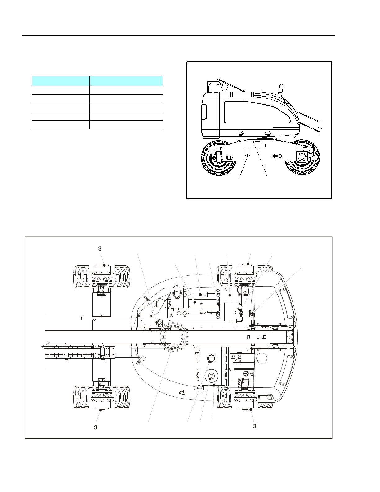
SECTION 1 - SPECIFICATIONS
Figure 1-1. Serial Number Location
SERIAL NUMBER
STAMPED ON FRAME
SERIAL NUMBER
PLATE
1
7
6
4
8
3
9
20
21, 22
14,15,16,17,18,19
8,9,10,11,12,13
5
Figure 1-2. Operator Maintenance and Lubrication Diagram
1.12 WELDER, HYDRAULIC (OPTION)
Table 1-21.Welder Specifications - Model 225-4
Description Specification
Weld Amps 225
Strike Weld 75
Weld Voltage 21.6 - 28 DC
Freque ncy 60 Hz, KVA - 4.2 Kw, Single Phase
Oil Flow 18.8 Gpm, 2000 Psi.
1.13 SERIAL NUMBER LOCATION
A serial number plate is affixed to the left rear side of the
frame. If the serial number plate is damaged or missing,
the machine serial number is stamped on the left side of
the frame.
1-6 – JLG Lift – 3120895
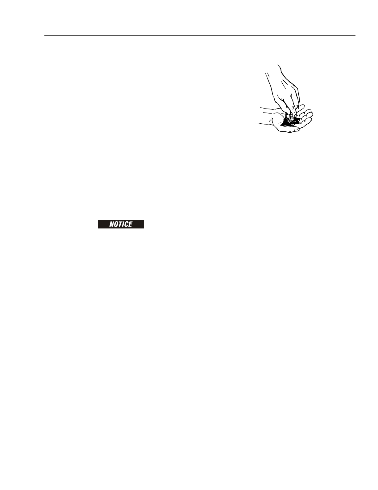
SECTION 1 - SPECIFICATIONS
1.14 OPERATOR MAINTENANCE AND LUBRICATION
NOTE: The following numbers correspond to those in Figure
1-2., Operator Maintenance and Lubrication Diagram.
Table 1-22. Lubrication Specifications
KEY SPECIFICATIONS
MPG Multipurpose Grease having a minimum dripping point of 350°
F (177° C). Excellent water resistance and adhesive qualities,
and being of extreme pressure type.
(Timken OK 40 pounds minimum.)
EPGL Extreme Pressure Gear Lube (oil) meeting API service classifi-
c at io n G L- 5 o r M IL- Sp e c M IL- L-2 1 05
HO Hydraulic Oil. API service classification GL-3, e.g. Mobilfluid
424.
EO Engine (crankcase) Oil. Gas - API SF, SH, SG class, MIL-L-
2104. Diesel - API CC/CD class, MIL-L-2104B/MIL-L-2104C.
OGL Open Gear Lubricant - Mobiltac 375 or equivalent.
LUBRICATION INTERVALS ARE BASED ON MACHINE OPERATION
UNDER NORMAL CONDITIONS. FOR MACHINES USED IN MULTISHIFT OPERATIONS AND/OR EXPOSED TO HOSTILE ENVIRONMENTS OR CONDITIONS, LUBRICATION FREQUENCIES MUST BE
INCREASED ACCORDINGLY.
NOTE: It is recommended as a good practice to replace all
filters at the same time.
1. Swing Bearing - Internal Ball Bearing
Lube Point(s) - 2 Grease Fittings
Capacity - A/R
Lube - MPG
Interval - Every 3 months or 150 hrs of operation
Comments - Fittings in center of bearing: Remote
Access is optional
2. Wheel Bearings (2WD Only)
Lube Point(s) - Repack
Capacity - A/R
Lube - MPG
Interval - Every 2 years or 1200 hours of operation
3. Wheel Drive Hub
Lube Point(s) - Level/Fill Plug
Capacity - 17 oz. (0.5 L) - 1/2 Full
Lube - EPGL
Interval - Check level every 3 months or 150 hrs of
operation; change every 2 years or 1200 hours of
operation
4. Hydraulic Return Filter
Interval - Change after first 50 hrs. and every 6
months or 300 hrs. thereafter or whenever Charge
Filter is replaced.
5. Hydraulic Charge Filter
Interval - Change after first 50 hrs. and every 6
months or 300 hrs. thereafter or as indicated by
Condition Indicator.
6. Hydraulic Tank
Lube Point(s) - Fill Cap
Capacity - 40.0 gal. tank (151L) 52.0 gal. system
(196.8L)
Lube - HO
Interval - Check Level daily; Change every 2 years or
1200 hours of operation.
3120895 – JLG Lift – 1-7
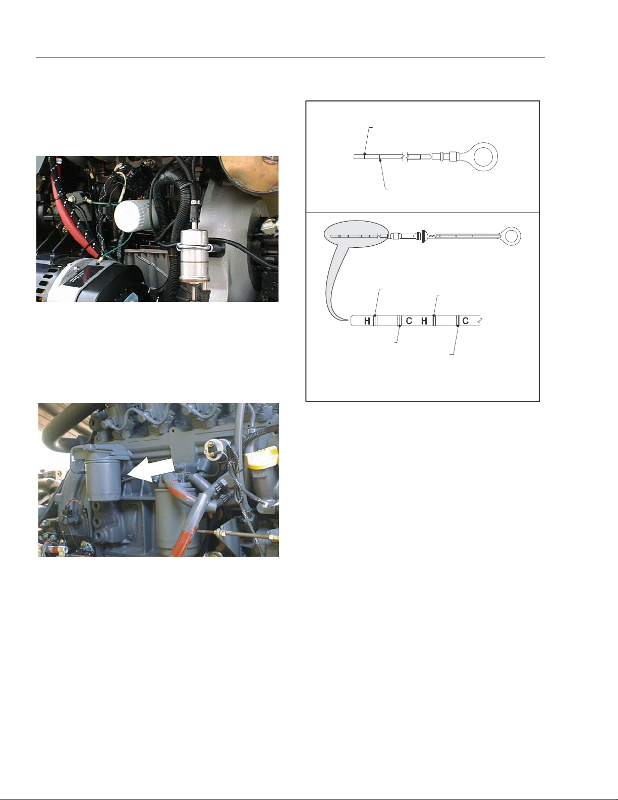
SECTION 1 - SPECIFICATIONS
MINIMUM LEVEL,
OIL HOT
MINIMUM OIL
LEVEL
MINIMUM LEVEL,
OIL COLD
NOTE: Hot oil checks should not be made until the engine
has been shut down for a period of 5 minutes.
MAXIMUM LEVEL,
OIL HOT
MAXIMUM LEVEL,
OIL COLD
MAXIMUM OIL
LEVEL
Figure 1-3. Deutz Engine Dipstick
7. Suction Strainers
Lube Point(s) - 2
Interval - Every 2 years or 1200 hours of operation,
remove and clean at time of hydraulic oil change.
8. Oil Change w/Filter - Ford
Lube Point(s) - Fill Cap/Spin-on Element (JLG P/N
7014501)
Capacity - 4.5 Quarts
Lube - EO
Interval - 3 Months or 150 hours of operation
Comments - Check level daily/Change in accordance with engine manual.
9. Oil Change w/Filter - Deutz
Lube Point(s) - Fill Cap/Spin-on Element (JLG P/N
7016331)
Capacity - 6.3 qt. (5.9) engine
Lube - EO
Interval - Every Year or 1200 hours of operation
Comments - Check level daily/Change in accordance with engine manual. Refer to Figure 1-3.,
Deutz Engine Dipstick.
10. Oil Change w/Filter - Isuzu
Lube Point(s) - Fill Cap/Spin-on Element (JLG P/N
7022111)
Capacity - 6 qt. (5.6L) engine; 6.5 qt. (6.1L) w/cooler
Lube - EO
Interval - 3 Months or 150 hours of operation
Comments - Check level daily/Change in accordance with engine manual.
11. Oil Change w/Filter - Caterpillar
Lube Point(s) - Fill Cap/Spin-on Element (JLG P/N
7026855)
Capacity - 10 Quarts (9.4 L)
Lube - EO
Interval - Every Year or 600 hours of operation
Comments - Check level daily/Change in accordance with engine manual.
1-8 – JLG Lift – 3120895
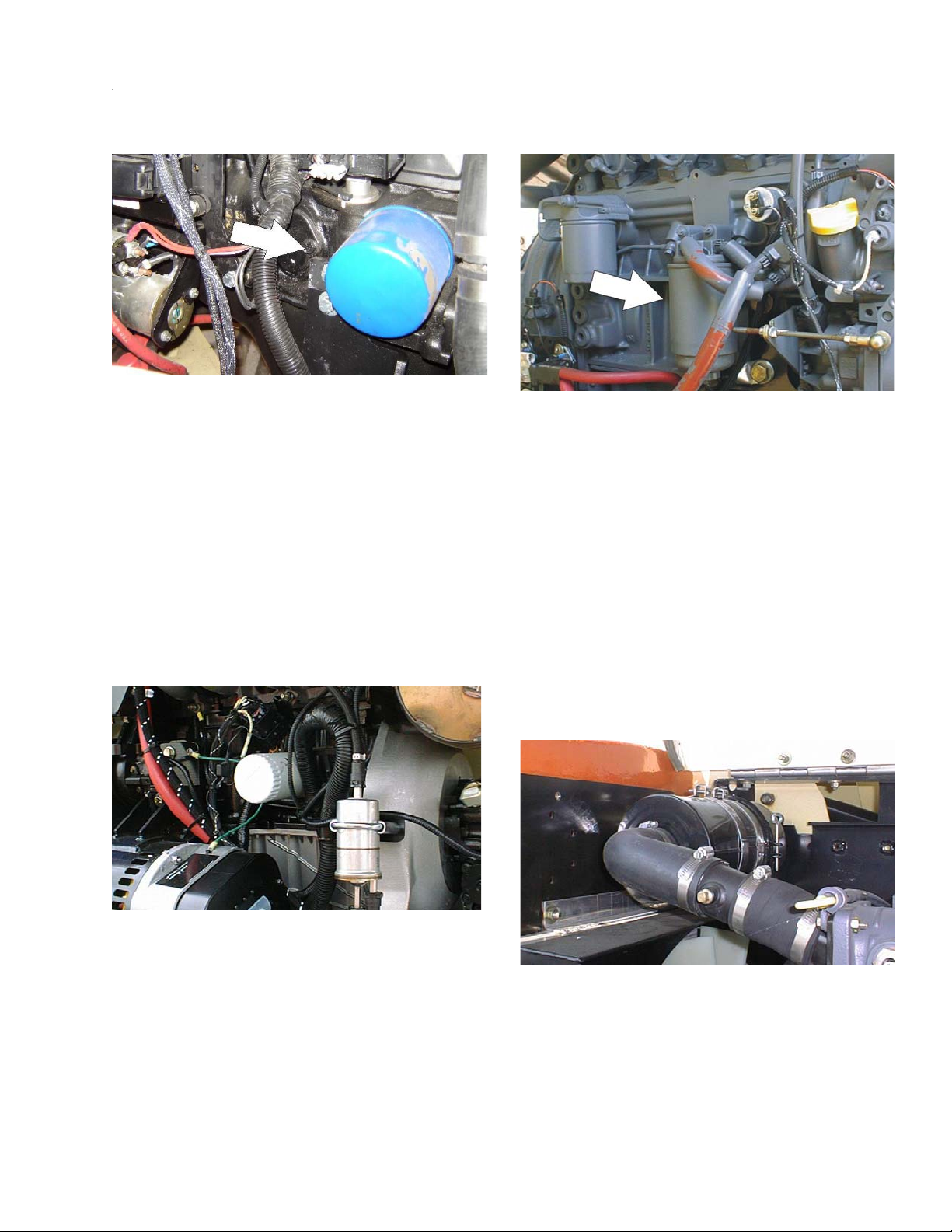
SECTION 1 - SPECIFICATIONS
12. Oil Change w/Filter - GM
Lube Point(s) - Fill Cap/Spin-on Element
(JLG P/N 7027965)
Capacity - 4.5 qt. (4.25 L) w/filter
Lube - EO
Interval - 3 Months or 150 hours of operation
Comments - Check level daily/Change in accordance with engine manual.
13. Oil Change w/Filter - Perkins
Lube Point(s) - Fill Cap/Spin-on Element (JLG P/N
7026855)
Capacity - 10 Quarts (9.4 L)
Lube - EO
Interval - Every Year or 600 hours of operation
Comments - Check level daily/Change in accordance with engine manual.
14. Fuel Filter - Ford
15. Fuel Filter - Deutz
Lube Point(s) - Replaceable Element
Interval - Every Year or 600 hours of operation
16. Fuel Filter - Isuzu
Lube Point(s) - Replaceable Element
Interval - Every Year or 600 hours of operation
17. Fuel Filter - Caterpillar
Lube Point(s) - Replaceable Element
Interval - Every Year or 600 hours of operation
18. Fuel Filter (Gasoline) - GM
Lube Point(s) - Replaceable Element
Interval - Every 6 months or 300 hours of operation
19. Fuel Filter - Perkins
Lube Point(s) - Replaceable Element
Interval - Every Year or 600 hours of operation
20. Air Filter
Lube Point(s) - Replaceable Element
Interval - Every Year or 600 hours of operation
Lube Point(s) - Replaceable Element
Interval - Every 6 months or 300 hours of operation
or as indicated by the condition indicator
3120895 – JLG Lift – 1-9
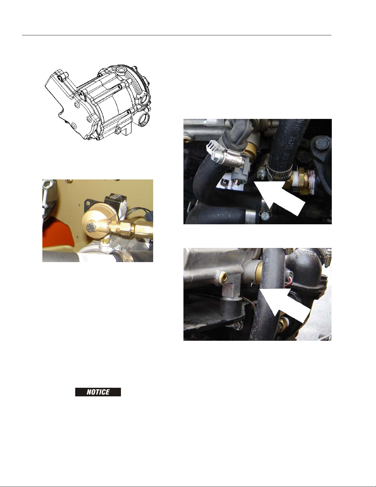
SECTION 1 - SPECIFICATIONS
21. Electronic Pressure Regulator (LP only)
Interval - 3 Months or 150 hours of operation
Comments - Drain oil build up. Refer to Draining Oil
Build Up From The Propane Regulator
22. Fuel Filter (Propane) - GM Engine
2. Start the engine and bring to operating temperature.
3. With the engine running, close the manual tank
valve and run the engine out of fuel.
4. Push in the Emergency Switch once the engine
stops.
5. Disconnect the electrical connection to the LPG fuel
temperature sensor in the auxiliary fuel port of the
EPR.
6. Remove the retainer clip for the LPG fuel temperature sensor and remove the sensor from the regulator body.
Interval - 3 Months or 150 hours of operation
Comments - Replace filter. Refer to Propane Fuel Filter Replacement
Draining Oil Build Up From The Propane Regulator
During the course of normal operation oils may build
inside the primary and secondary chambers of the propane pressure regulator. These oils may be a result of
poor fuel quality, contamination of the fuel supply
chain, or regional variation in the make up of the fuel. If
the build up of the oil is significant this can effect the
operation of the fuel control system. Refer to Section
1.14, Operator Maintenance and Lubrication for maintenance intervals. More frequent draining may be
required if the fuel supply has been contaminated.
FOR BEST RESULTS WARM THE ENGINE TO OPERATING TEMPERATURE BEFORE DRAINING. THIS WILL ALLOW THE OILS TO
BE LIQUID AND FLOW FREELY FROM THE REGULATOR.
1. Move the equipment to a well ventilated area.
Ensure there are no external ignition sources.
NOTE: Have a small container ready to collect oil that will
drain freely from the regulator at this point.
7. Once all of the oil has been drained, reinstall the
LPG fuel temperature sensor and reconnect the
electrical connector.
8. Open the fuel tank manual valve.
9. Start the engine and verify all connections are
secure.
10. Dispose of any drained oil in a safe and proper fashion.
1-10 – JLG Lift – 3120895
 Loading...