


JLG 3969 Parts Manual

Illustrated Parts Manual
Model
3369electric
3969electric
3120769
May 31, 2013


REVISION LOG
March 22, 1999 - Original Issue Of Manual (Was part of complete Manual #3120597)
(Model 3369 Manual edited to 0010498 Revision 22)
(Model 3969 Manual edited to 0010487 Revision 24)
June 29, 1999 Updated Pages - Cover, Effectivity Page & 2-19
November 10, 1999 Updated Pages - Cover, Effectivity Page & 1-4
September 29, 2000 Revised - (Model 3369 Manual edited to 0010498 Revision 31)
(Model 3969 Manual edited to 0010487 Revision 27)
August 15, 2003 Revised - (Model 3369 Manual edited to 0010498 Revision 34)
(Model 3969 Manual edited to 0010487 Revision 32)
September 1, 2003 Revised - Updated Section 3
January 31, 2007 - Revised Manual
November 1, 2010 - Revised Manual
May 31, 2013 - Revised Manual
3120769 A

REVISION LOG
B

TABLE OF CONTENTS
FIGURE NO. TITLE PAGE NO.
SECTION 1 - FRAME
1-1 FRAME AND STEERING INSTALLATION . . . . . . . . . . . . . . . . . . . . . . . . . . . . . . . . . . . .1-2
1-2 TIRE AND WHEEL DRIVE INSTALLATION . . . . . . . . . . . . . . . . . . . . . . . . . . . . . . . . . . .1-6
1-3 DRIVE HUB ASSEMBLY . . . . . . . . . . . . . . . . . . . . . . . . . . . . . . . . . . . . . . . . . . . . . . . . .1-8
1-4 DRIVE BRAKE ASSEMBLY . . . . . . . . . . . . . . . . . . . . . . . . . . . . . . . . . . . . . . . . . . . . . . .1-10
1-5 ELECTRICAL COMPONENTS INSTALLATIONS (FRAME MOUNTED) . . . . . . . . . . . . .1-12
1-6 BATTERY CHARGER ASSEMBLY . . . . . . . . . . . . . . . . . . . . . . . . . . . . . . . . . . . . . . . . . .1-18
1-7 BATTERY CHARGER ASSEMBLY - 22VAC/50Hz (SERVICE REPLACEMENT) . . . . . . .1-22
1-8 FRAME MOUNTED COMPONENTS INSTALLATION . . . . . . . . . . . . . . . . . . . . . . . . . . .1-24
SECTION 2 - GROUND COMPONENTS
2-1 HYDRAULIC COMPONENTS INSTALLATION. . . . . . . . . . . . . . . . . . . . . . . . . . . . . . . . .2-2
2-2 CONTROL VALVE ASSEMBLY (PRIOR TO SEPTEMBER 1994) . . . . . . . . . . . . . . . . . .2-6
2-3 CONTROL VALVE ASSEMBLY (SEPTEMBER 1994 TO PRESENT). . . . . . . . . . . . . . . .2-8
2-4 PUMP ASSEMBLY . . . . . . . . . . . . . . . . . . . . . . . . . . . . . . . . . . . . . . . . . . . . . . . . . . . . . .2-10
2-5 GROUND CONTROL BOX ASSEMBLY (PRIOR TO OCTOBER 1994) . . . . . . . . . . . . . .2-12
2-6 GROUND CONTROL BOX ASSEMBLY (OCTOBER 1994 TO PRESENT) . . . . . . . . . . .2-14
2-7 COVERS INSTALLATION. . . . . . . . . . . . . . . . . . . . . . . . . . . . . . . . . . . . . . . . . . . . . . . . .2-18
SECTION 3 - SCISSOR ARMS
3-1 SCISSOR ARMS INSTALLATION - MODEL 3369 . . . . . . . . . . . . . . . . . . . . . . . . . . . . . .3-2
3-2 SCISSOR ARMS INSTALLATION - MODEL 3969 . . . . . . . . . . . . . . . . . . . . . . . . . . . . . .3-6
SECTION 4 - PLATFORM
4-1 PLATFORM COMPONENTS INSTALLATION . . . . . . . . . . . . . . . . . . . . . . . . . . . . . . . . .4-2
4-2 MANUAL PLATFORM EXTENSION INSTALLATION . . . . . . . . . . . . . . . . . . . . . . . . . . . .4-8
4-3 PLATFORM CONSOLE BOX ASSEMBLY (PRIOR TO S/N 71506) . . . . . . . . . . . . . . . .4-12
4-4 PLATFORM CONSOLE BOX ASSEMBLY (S/N 71506 TO PRESENT) . . . . . . . . . . . . . .4-16
4-5 CONTROLLER ASSEMBLY - PQ (PRIOR TO S/N 71506) . . . . . . . . . . . . . . . . . . . . . . .4-18
4-6 CONTROLLER ASSEMBLY - PQ (S/N 71506 TO PRESENT) . . . . . . . . . . . . . . . . . . . . .4-20
SECTION 5 - CYLINDER
5-1 LIFT CYLINDER ASSEMBLY . . . . . . . . . . . . . . . . . . . . . . . . . . . . . . . . . . . . . . . . . . . . . .5-2
5-2 STEER CYLINDER ASSEMBLY . . . . . . . . . . . . . . . . . . . . . . . . . . . . . . . . . . . . . . . . . . .5-6
SECTION 6 - HYDRAULIC
6-1 HYDRAULIC DIAGRAM . . . . . . . . . . . . . . . . . . . . . . . . . . . . . . . . . . . . . . . . . . . . . . . . . .6-2
SECTION 7 - ELECTRICAL
7-1 ELECTRICAL DIAGRAM LIST . . . . . . . . . . . . . . . . . . . . . . . . . . . . . . . . . . . . . . . . . . . . .7-2
7-2 ELECTRICAL SCHEMATIC - PLATFORM (PRIOR TO S/N 71506) . . . . . . . . . . . . . . . . .7-4
7-3 ELECTRICAL SCHEMATIC - PLATFORM (S/N 71506 TO PRESENT) . . . . . . . . . . . . . .7-5
7-4 ELECTRICAL DIAGRAM - STANDARD (PRIOR TO S/N 71506) . . . . . . . . . . . . . . . . . . .7-6
7-5 ELECTRICAL DIAGRAM - STANDARD (S/N 71506 TO PRESENT) . . . . . . . . . . . . . . . .7-7
7-6 MAIN ELECTRICAL CONNECTOR AND TOOLS. . . . . . . . . . . . . . . . . . . . . . . . . . . . . . .7-8
3120769 i

TABLE OF CONTENTS
FIGURE NO. TITLE PAGE NO.
SECTION 8 - DECALS
8-1 DECALS INSTALLATION (PRIOR TO S/N 69694). . . . . . . . . . . . . . . . . . . . . . . . . . . . . .8-2
8-2 DECALS INSTALLATION (S/N 69694 TO PRESENT) . . . . . . . . . . . . . . . . . . . . . . . . . . .8-8
SECTION 9 - RECOMMENDED SERVICE PARTS STOCK
SECTION 10 - SPECIAL OPTIONS
ii 3120769

SECTION 1 FRAME
S
TABLE OF CONTENTS
FIGURE DESCRIPTION PAGE
1-1 FRAME AND STEERING INSTALLATIONS . . . . . . . . . . . . . . . . . . . . . . . . . . . . . . . . . . . . . . . 1-2
1-2 TIRE AND WHEEL DRIVE INSTALLATION. . . . . . . . . . . . . . . . . . . . . . . . . . . . . . . . . . . . . . 1-6
1-3 DRIVE HUB ASSEMBLY. . . . . . . . . . . . . . . . . . . . . . . . . . . . . . . . . . . . . . . . . . . . . . . . . . . . . . . 1-8
1-4 DRIVE BRAKE ASSEMBLY. . . . . . . . . . . . . . . . . . . . . . . . . . . . . . . . . . . . . . . . . . . . . . . . . . . . . 1-10
1-5 ELECTRICAL COMPONENTS INSTALLATIONS (FRAME MOUNTED).. . . . . . . . . . . . . . . . . . 1-12
1-6 BATTERY CHARGER ASSEMBLY . . . . . . . . . . . . . . . . . . . . . . . . . . . . . . . . . . . . . . . . . . . . . . . 1-18
1-7 BATTERY CHARGER ASSEMBLY - 220VAC/50Hz (SERVICE REPLACEMENT). . . . . . . . . . . 1-22
1-8 FRAME MOUNTED COMPONENTS INSTALLATION.. . . . . . . . . . . . . . . . . . . . . . . . . . . . . . . . 1-24
E
C
T
I
O
N
1
F
R
A
M
E
3120769 1-1
SECTION 1 FRAME
S
E
C
T
I
O
N
1
F
R
A
M
E
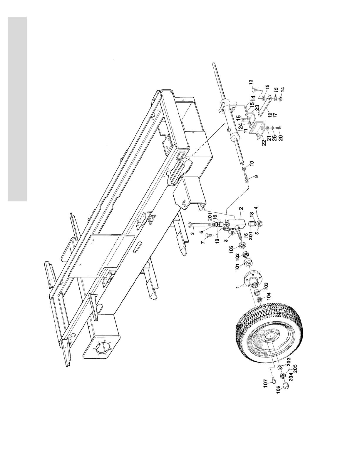
FIGURE 1-1.FRAME AND STEERING INSTALLATION
1-2 3120769

SECTION 1 FRAME
.
FIGURE 1-1. FRAME AND STEERING INSTALLATION
FIG & ITEM # PART NUMBER DESCRIPTION QTY. REV.
FRAME AND STEERING INSTALLATION Ref.
Frame Weldment Options: 1
2360370 3369/3969electric (Prior to S/N 71506)
2360534 3369electric (S/N 71506 to Present)
STEERING AND SPINDLES INSTALLATION OPTIONS:
0252243 Steering and Spindles - Standard Ref. 8
0255552 Steering and Spindles - CSA Ref. 5
1 Use
1001139010
2 Spindle Options:
4130286 Standard 2
4130327 CSA 2
3 3421988 Kingpin 2
4 3450810 Pin, Cotter 1/4” x 2 1/2” 2
5 3313003 Nut, Slotted 1 1/4” - 7NC 2
6 0440162 Washer, Thrust 2
7 0642016 Bolt 5/8”-18NC x 2” 2
8 3312005 Locknut 5/8”-18NC 2
9 3841146 Rod-End 2
10 3322002 Nut, Jam 5/8”-18NC 2
11 Use 1683695 Steer Cylinder Assembly (See Section 5 for Breakdown)
1683695 Steer Cylinder Assembly (See Section 5 for Breakdown)
12 3340644 Pad, Wear 1
13 0641510 Bolt 5/8”-18NC x 1 1/4” 2
14 3311505 Locknut 5/8”-18NC 4
15 4751500 Flatwasher 5/16” 8
16 3020022 Grease A/R
17 4070809 Shim A/R
18 3780182 O-Ring 4
19 Not Used
20 0641608 Bolt 3/8”-16NC x 1” (S/N 80825 to Present) 2
21 4740453 Flatwasher 3/8” (S/N 80825 to Present) 2
22 0182002 Angle (S/N 80825 to Present) 1
23 0182000 Angle (S/N 80825 to Present) 1
24 0641514 Bolt 5/16”-18NC x 1 3/4” (S/N 80825 to Present) 2
25 0100019 Loctite (Not Shown) (S/N 80825 to Present) A/R
26 4711600 Flatwasher 3/8” (Narrow) (S/N 82838 to Present) 2
Hub Assembly (Includes Items 101-107) (was p/n 2780186) 2
1
(Prior to S/N 47596) (was p/n 1682527)
1
(S/N 47596 to Present)
S
E
C
T
I
O
N
1
F
R
A
M
E
3120769 1-3

SECTION 1 FRAME
S
E
C
T
I
O
N
1
F
R
A
M
E
FIGURE 1-1. FRAME AND STEERING INSTALLATION (CONTINUED)
FIG & ITEM # PART NUMBER DESCRIPTION QTY. REV.
HUB ASSEMBLIES Ref.
2780186 Original Equipment Ref. C
1001139010 Service Replacement Ref. A
Note: Original Equipment components may have been
replaced with Service Replacement components,
Identify hub by bolts or studs before ordering parts.
101 Kit Cup, Bearing - Inner (1 Per Hub) 2
102 Kit Cone, Bearing - Inner (1 Per Hub) 2
103 Kit Cup, Bearing - Outer (1 Per Hub) 2
104 Kit Cone, Bearing - Outer (1 Per Hub) 2
105 Kit Seal (1 Per Hub) 2
106 Use
1001102354
107 Hardware Options (5 Per Spindle): 10
0630016 Bolt, Wheel 1/2in x 20NF(Hub Assembly - 2780186)
7016360 Stud, Wheel 1/2in x 20NF (Hub Assembly -
3300407 Nut, Wheel 1/2in x 20NF (Hub Assembly -
2900804 Bearing & Seal Kit (Includes Qty 1 Items 101-105) (1 Per
Cap, Dust (1 Per Hub) (was p/n 7012524) 2
1001139010)
1001139010)
— — — — — — — — — —
2
Hub) (Hub Assemblies 2780186 & 1001139010)
4130286 SPINDLE WELDMENT - STANDARD Ref. A
4130327 SPINDLE WELDMENT - CSA Ref.
201 0961621 Bushing, Bronze (2 Per Spindle) 2
202 Not Used
203 7012542 Washer (1 Per Spindle) 2
—
1-4 3120769

SECTION 1 FRAME
FIGURE 1-1. FRAME AND STEERING INSTALLATION (CONTINUED)
FIG & ITEM # PART NUMBER DESCRIPTION QTY. REV.
S
E
C
T
I
O
N
1
F
R
A
M
E
3120769 1-5
SECTION 1 FRAME
S
E
C
T
I
O
N
1
F
R
A
M
E
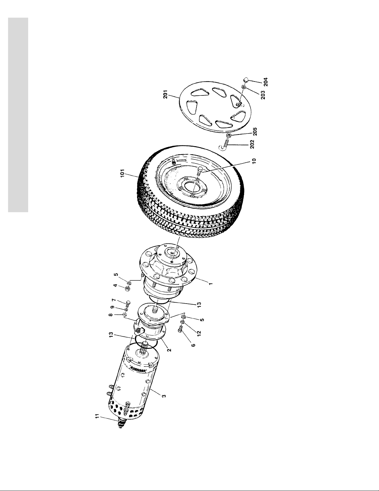
FIGURE 1-2.TIRE AND WHEEL DRIVE INSTALLATION
1-6 3120769

SECTION 1 FRAME
FIGURE 1-2. TIRE AND WHEEL DRIVE INSTALLATION
S
E
FIG & ITEM # PART NUMBER DESCRIPTION QTY. REV.
WHEEL DRIVE INSTALLATION OPTIONS: Ref.
0254491 Standard (Prior to S/N 71506) Ref. 10
0255203 Standard (S/N 71506 to Present) Ref. 8
0256908 UL Ref.
1 2780204 Drive Hub Assembly (See Figure 1-3 for Breakdown) 2
2 0920090 Drive Brake Assembly (See Figure 1-4 for Break-
down)
3 3160186 Drive Motor Assembly 2
2900811 Repair Kit (Includes All Bearings, Brushes, Springs
and Wavy Washer (1 Per Motor)
7012546 Field Coil Kit (1 Per Motor) 2
7019609 Head Band Assembly (1 Per Motor) 2
4 3321805 Locknut 1/2”-20NF 18
5 4711800 Flatwasher 1/2” Narrow 22
6 0641811 Bolt 1/2”-13NC x 1 3/8” 4
7 0641608 Bolt 3/8”-16NC x 1” 8
8 4711600 Flatwasher 3/8” Narrow 8
9 4761600 Lockwasher 3/16” 8
10 0630016 Bolt, Wheel 10
11 3990053 Sensor, Tach Drive 2
7012609 Boot 2
12 4761800 Lockwasher 1/2” 4
13 3790240 O-Ring 2
2
2
4
C
T
I
O
N
1
F
R
A
M
E
TIRE AND WHEEL INSTALLATION OPTIONS:
101 0252430 Tire And Wheel Assembly (Foam-Filled) (Sold as an
Assembly)
4520151 Tire And Wheel Assembly (Non-Marking Optional)
(Sold as an Assembly)
0252754 HUBCAP INSTALLATION (OPTIONAL) Ref. B
201 1670633 Hubcap (Prior to S/N 27282) 4
1670806 Hubcap (S/N 27282 to Present) 4
202 0630455 J-Bolt 5/16”-18NC 8
203 4761500 Lockwasher 5/16” 8
204 3300356 Nut, Acorn 5/16”-18NC 8
205 3311501 Nut 5/16”-18NC 8
4
4
3120769 1-7
SECTION 1 FRAME
S
E
C
T
I
O
N
1
F
R
A
M
E
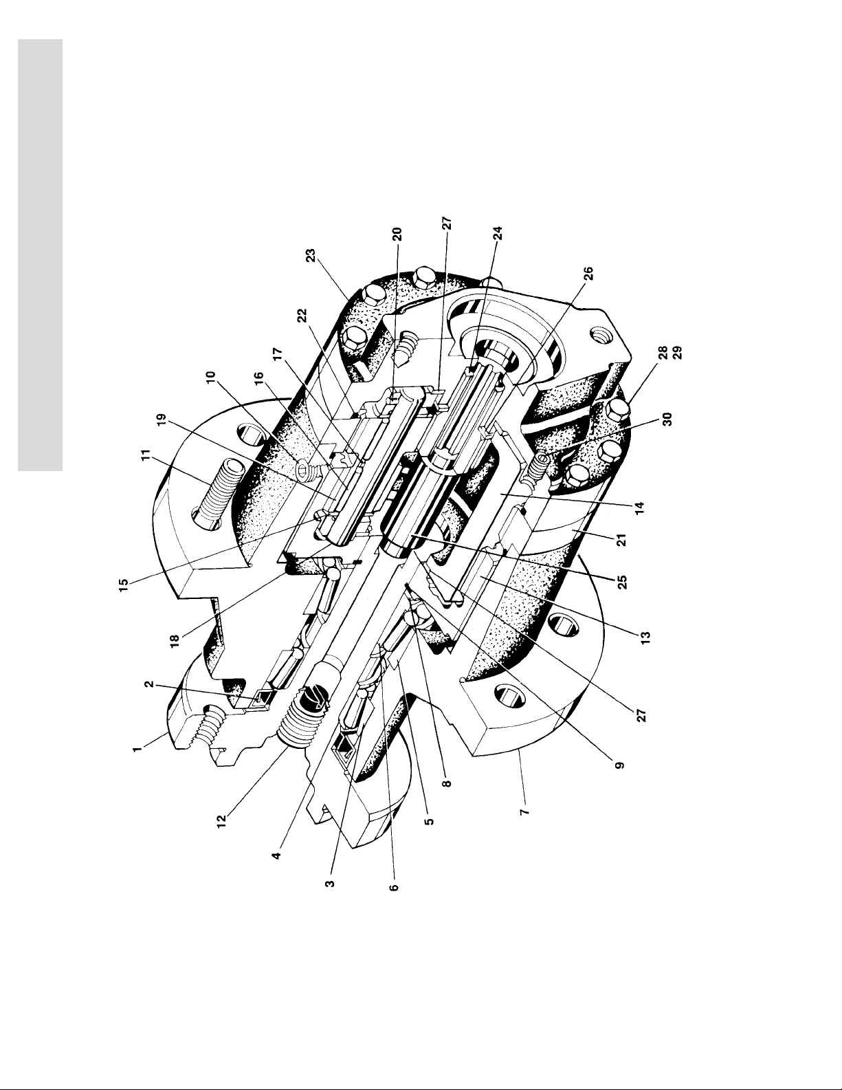
FIGURE 1-3.DRIVE HUB ASSEMBLY
1-8 3120769

SECTION 1 FRAME
.
FIGURE 1-3. DRIVE HUB ASSEMBLY
FIG & ITEM # PART NUMBER DESCRIPTION QTY. REV.
2780204 DRIVE HUB ASSEMBLY Ref. B
Hub-Shaft Assembly 1
1 7010487 Spindle 1
2KitSeal, Lip 1
3 7000255 Cup, Bearing (Outer) 1
4 7000256 Cone, Bearing (Outer) 1
5 7000257 Cup, Bearing (Inner) 1
6 7000258 Cone, Bearing (Inner) 1
7 7000259 Housing 1
8 Kit Washer, Thrust 1
9 Kit Ring, Retaining 1
10 7000242 Plug, Pipe - 1/4”NPTF 2
11 7000241 Stud, Wheel 1/2”-20NF 9
12 7001952 Plug, Pipe - 3/4”NPTF 1
13 7000246 Gear, Internal 1
Carrier Assembly 1
14 7001931 Carrier 1
15 7001985 Washer, Tanged Thrust 6
16 7001909 Bearing, Needle 96
17 7000263 Spacer, Thrust 3
18 7001911 Shaft, Planet 3
19 7001987 Gear, Cluster 3
20 7010474 Rollpin 3
21 7001988 Gear, Ring 1
22 Kit O-Ring 2
23 7000209 Cover, Input 1
24 7010488 Gear, Sun 1
25 7000269 Spacer, Input 1
26 7000270 Washer, Thrust 1
27 7000253 Washer, Thrust 2
28 7000217 Bolt, Hex 8
29 7000214 Bolt, Shoulder 4
30 7000242 Plug, Pipe - 1/4”NPTF 1
S
E
C
T
I
O
N
1
F
R
A
M
E
2900034 Seal Kit (Includes Items 2,8,9, and 22) 1
3120769 1-9
SECTION 1 FRAME
S
E
C
T
I
O
N
1
F
R
A
M
E
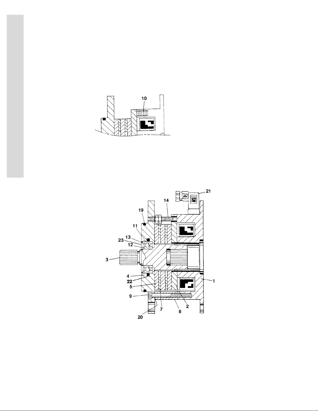
FIGURE 1-4.DRIVE BRAKE ASSEMBLY
1-10 3120769

SECTION 1 FRAME
.
FIGURE 1-4. DRIVE BRAKE ASSEMBLY
FIG & ITEM # PART NUMBER DESCRIPTION QTY. REV.
0920090 DRIVE BRAKE ASSEMBLY Ref. A
1 7012552 Magnet and Coil Assembly 1
2 7012582 Armature 1
3 7012554 Shaft 1
4 Not Available Plate, Mounting 1
5 Kit Plate, Friction (Solid) 3
6 Not Used
7 Kit Plate, Outer 2
8 7012692 Spacer 3
9 7014116 Bolt, Metric Socket Head 3
10 Kit Spring, Compression 8
11 7026609 Bearing, Ball 1
12 7014129 Ring, Retainer (External) 1
13 7014130 Ring, Retainer (Internal) 1
14 7012689 Manual Release Assembly 3
15 Not Used
16 Not Used
17 Not Used
18 Not Used
19 3790240 O-Ring 1
20 7012691 Shim A/R
21 7012580 Connector, Electrical 1
22 3790225 O-Ring (January 1995 to Present) 1
23 7014128 Seal (S/N 73241 to Present) 1
— — — — — — — — — —
7012583 Repair Kit (Includes Items 5,7,10,11, and 22 1
S
E
C
T
I
O
N
1
F
R
A
M
E
3120769 1-11
SECTION 1 FRAME
S
E
C
T
I
O
N
1
F
R
A
M
E
FIGURE 1-5.ELECTRICAL COMPONENTS INSTALLATIONS (FRAME MOUNTED)
1-12 3120769

SECTION 1 FRAME
.
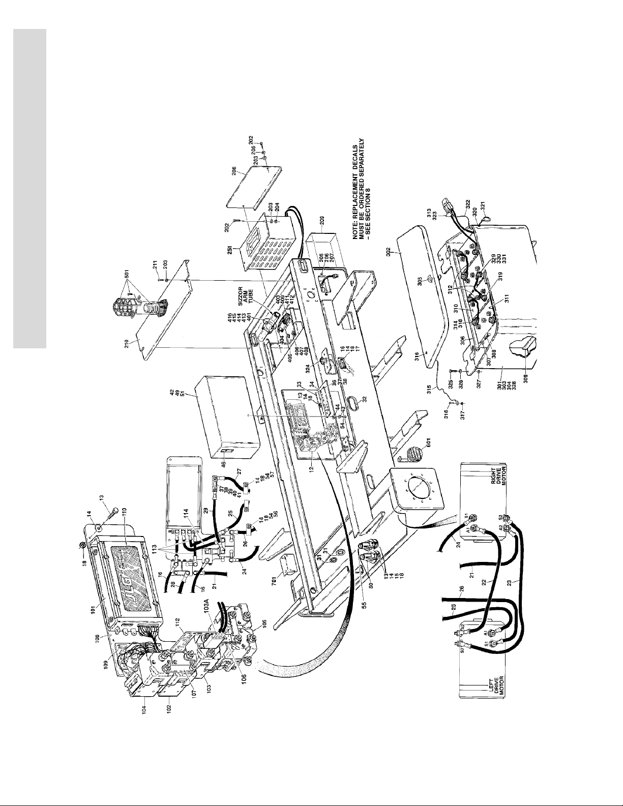
FIGURE 1-5. ELECTRICAL COMPONENTS INSTALLATIONS (FRAME MOUNTED)
FIG & ITEM # PART NUMBER DESCRIPTION QTY. REV.
DRIVE CONTACTOR INSTALLATION OPTIONS: Ref.
0254491 Standard (Prior to S/N 71506) Ref. 10
0255203 Standard (S/N 71506 to Present) Ref. 8
0256908 UL Ref.
1 to 11 Not Used
12 0254549 Contactor Plate Assembly (Includes Items 101-111 and
other diodes,coils, fuse and wiring) (Purchase fuses locally)
13 0641408 Bolt 1/4”-20NC x 1” 9
14 4711400 Flatwasher 1/4” A/R
15 Not Used
16 1060540 Cable Assembly 1
17 0641416 Bolt 1/4”-20NC x 2” 4
18 3311405 Locknut 1/4”-20NC A/R
19 to 20 Not Used
21 1060549 Cable - 105”/267cm 1
22 1060429 Cable - 39”/99cm 1
23 1060430 Cable - 36”/91.5cm 1
24 1060550 Cable - 108”/274cm 1
25 1060551 Cable - 90”/228cm 1
26 1060552 Cable - 90”/228cm 1
27 1060553 Cable - 90”/228cm 1
28 1060554 Cable - 108”/274cm 1
29 1060555 Cable - 18”/46cm 1
30 Not Used
31 2540023 Grommet 2
32 4060805 Flex-Trim (Prior to S/N 56587)
4060807 Flex-Trim (S/N 56587 to Present)
33 Plate, Mounting Options: 1
3537950 Prior to S/N 75352
3572196 S/N 75352 to Present
34 1320216 Clamp, Cable (Prior to S/N 75352) 1
35 Not Used
36 Screw Options: A/R
0721006 Screw #10-24NC x 3/4” (Prior to S/N 75352) 7
0721008 Screw #10-24NC x 1” (S/N 75352 to Present) 4
37 4751000 Flatwasher #10 13
38 3311005 Locknut #10-24NC 6
39 2400044 Fuseblock 1
40 Fuse Options: 1
2400045 Standard (Prior to S/N 28687)
2400053 Standard (S/N 28687 to Present
2400045 UL
41 0741010 Screw, Countersunk #10-24NC x 1 1/8” 2
42 4060873 Cover, Controller
43 4751400 Flatwasher 1/4” 1
44 3300353 Nut, Tinnerman 1
45 Not Used
1
15in./38cm
15in./38cm
1
S
E
C
T
I
2
O
N
1
F
R
A
M
E
3120769 1-13

SECTION 1 FRAME
S
E
C
T
I
O
N
1
F
R
A
M
E
FIGURE 1-5. ELECTRICAL COMPONENTS INSTALLATIONS (FRAME MOUNTED) (CONTINUED)
FIG & ITEM # PART NUMBER DESCRIPTION QTY. REV.
46 2560126 Handle, Pull 1
47 to 48 Not Used
49 4420008 Tape, Seal 7ft./2m
50 4360371
7012608 Fuse - 1.5 Amp (Black Version Only - Not Required on
51 1702310 Decal - Cable Rounting 1
52 Not Used
53 0100048 Sealant, Silicone RTV (Not Shown) A/R
54 0641406 Bolt 1/4”-20NC x 3/4” 4
55 4360349
56 1320270 Clamp, Cable (S/N 75352 to Present) 2
57 1320061 Clamp, Cable (S/N 75352 to Present) 2
0254549 CONTACTOR PLATE ASSEMBLY Ref.
101 7013310-ES Control Module Assembly 1
102 7013301 Contactor (Changeover) 1
7013316 Tip Repair Kit - 7013301 Contactor 1
103 7013306 Contactor (Main) 1
7013317 Tip Repair Kit - 7013306 Contactor 1
103A 7013332 Micro Switches Kit - 7013306 Contactor 1
104 7013303 Contactor (By-Pass) 1
7013318 Tip Repair Kit - 7013303 Contactor 1
105 7013302 Contactor (Forward/Reverse) 1
7013319 Tip Repair Kit - 7013302 Contactor 1
106 7013312 Fuse, Buss - 200 Amp 1
107 7013336 Bar, Buss 1
108 Not Serviced Plate, Mounting 1
109 7013307 Board, PC 1
7013314 Kit Board, PC 1
2400005 Fuse - 20 Amp 1
7013322 Fuse - 7 Amp 1
110 Not Serviced Decal 1
111 7013313 Harness (Module to Contactors) (Not Shown) 1
7013325 Connector, Electrical - 16 Pin (At PC Board) 1
7013326 Connector, Electrical - 17 Pin (At Control Module) 1
7013330 Connector, Electrical - 6 Pin (At Contactors) 5
7013327 Connector, Electrical - 15 Pin (To JLG Harness) 1
7013328 Connector, Electrical - 4 Pin (To JLG Harness) 1
7013320 Pin (Use with 7013325 & 7013326 Connectors) A/R
7013329 Socket (Use with 7013327 & 7013328 Connectors) A/R
7013331 Pin (Use with 7013330 Connector) A/R
112 7013315 Resistor/Bracket Assembly 1
113 70003552 Cable, Electrical (8.5in/21.5cm) 3
114 70003553 Cable, Electrical (10in/25.4cm) 1
Sensor, Level - 4.5
Blue and Orange Versions)
Sensor, Level - 2
°
°
1
1
1
1-14 3120769

SECTION 1 FRAME
FIGURE 1-5. ELECTRICAL COMPONENTS INSTALLATIONS (FRAME MOUNTED) (CONTINUED)
FIG & ITEM # PART NUMBER DESCRIPTION QTY. REV.
BATTERY CHARGER INSTALLATION OPTIONS: Ref.
0254496 Charger - 110VAC/60HZ - USA/CSA (Non UL) Ref. 4
0255536 Charger - 110VAC/60HZ - USA/CSA (UL) Ref.
0254497 Charger - 220VAC/50HZ - Latin America (Non UL) Ref. B
0255627 Charger - 220VAC/50HZ - Latin America (UL) Ref.
0257478 Charger - 220VAC/60HZ - USA/CSA/Latin America/Brazil
(Non UL)
0254498 Charger - 100VAC 50/60HZ - Japanese Spec. Ref. B
201 Not Used
202 0641406 Bolt 1/4”-20NC x 3/4” 3
203 4711400 Flatwasher 1/4” Narrow 5
204 3311405 Locknut 1/4”-20NC 1
205 4761400 Lockwasher 1/4” 4
206 0641408 Bolt 1/4”-20NC x 1” 2
207 3300181 Nut, Retainer 1/4”-20NC 2
208 3537637 Cover - Front 1
209 1701695 Decal 1
210 4060871 Cover - Top 1
211 3900022 Screw, Self-Tapping 1/4”-20NC x 3/4” 2
212 to 250 Not Used
251 Battery Charger Options: (See Figure 1-6 for Breakdown) 1
0400102 USA/CSA (Non UL) (Prior to S/N 60218)
0400162 USA/CSA (Non UL) (S/N 60218 to Present)
0400124 USA/CSA (UL)
0400103 Latin America (Non UL)
0400137 Latin America (UL)
0400158 USA/CSA/Latin American/Brazil (Non UL)
0400105 Japanese Spec.
Ref. 1
—
—
S
E
C
T
I
O
N
1
F
R
A
M
E
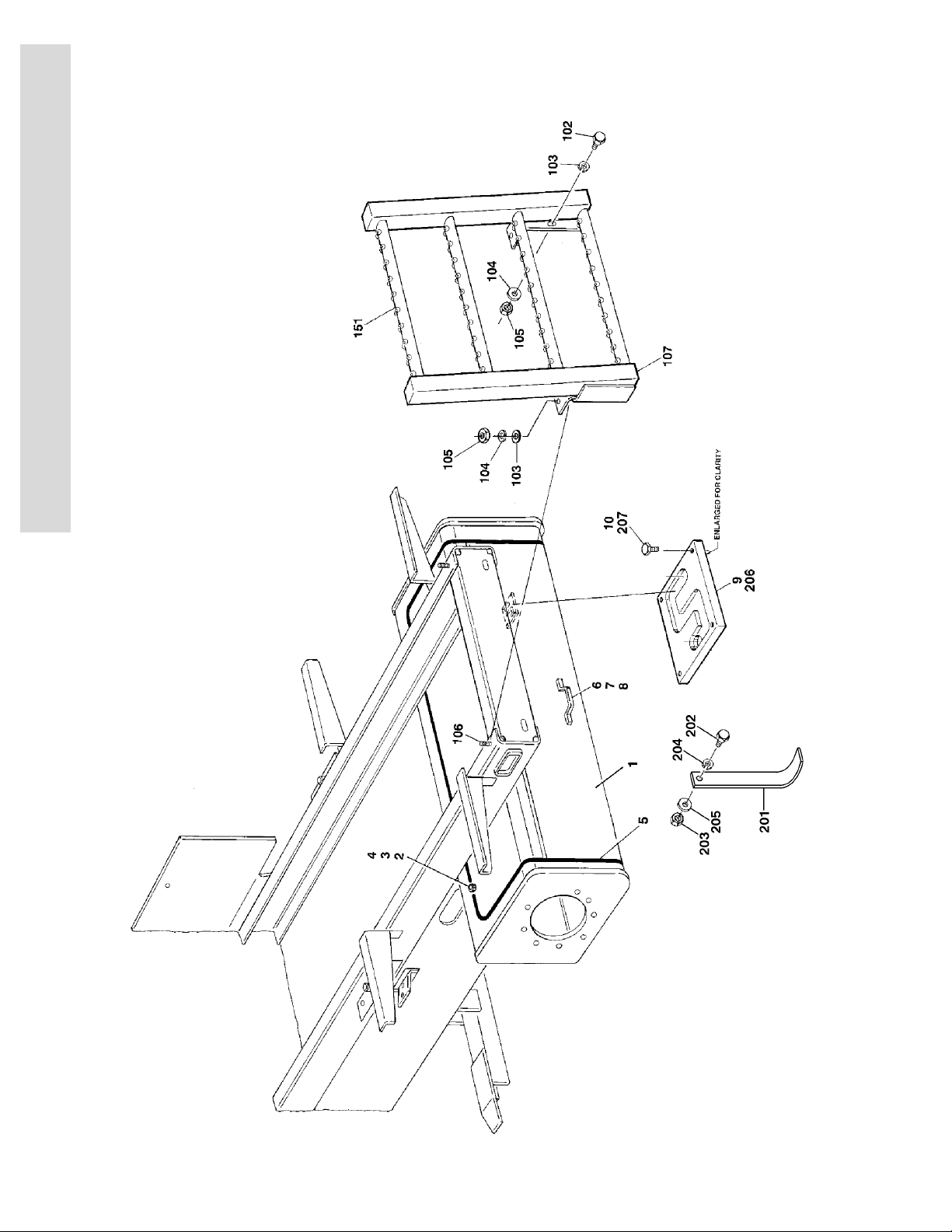
BATTERY BOX INSTALLATION OPTIONS: Ref.
0255087 Standard Ref. 7
0254276 HI-Output (Prior to S/N 75765) Ref. H
0258444 HI-Output (S/N 75765 to Present) Ref. 5
301 4844424 Battery Box Weldment 2
302 1670696 Cover, Battery Box 2
303 Cover, Insulator Options: 2
Not Required Standard
2820063 HI-Output
304 0100065 Adhesive (Prior to S/N 36134) A/R
305 2940073 Latch 2
306 4565640 Tube 2
307 4711500 Flatwasher 5/16” 8
308 0641512 Bolt 5/16”-18NC x 1 1/2” 4
309 3000003 Liner, Tray 2
310 Battery Options: 8
0400069 Battery - 6V225 (Wet)
0400112 Battery - 6V225 (Dry)
0400055 HI-Output Battery - 6V370 (Wet)
0400107 HI-Output Battery - 6V370 (Dry)
3120769 1-15

SECTION 1 FRAME
S
E
C
T
I
O
N
1
F
R
A
M
E
FIGURE 1-5. ELECTRICAL COMPONENTS INSTALLATIONS (FRAME MOUNTED) (CONTINUED)
FIG & ITEM # PART NUMBER DESCRIPTION QTY. REV.
311 1060405 Cable Assembly 2
312 1060561 Cable, Battery (Prior to August 1995) 6
1060092 Cable, Battery (August 1995 to Present) 6
313 0100048 Silicone Compound A/R
314 0100051 Grease, Terminal A/R
315 1060492 Lanyard 4
316 0641405 Bolt 1/4”-20NC x 5/8” 8
317 3311405 Locknut 1/4”-20NC 8
318 0840031 Boot, Terminal - “d” shape 10
319 0840032 Boot, Terminal - “b” shape 6
320 Gromment Options: 2
Not Required Standard
2540016 HI-Output
321 Ring Options: 2
Not Required Standard
3760170 HI-Output
322 Cable, Lanyard Options: 2
Not Required Standard
1060491 HI-Output
323 Handle, Pull Options: 2
Not Required Standard
1320172 HI-Output
324 3421799 Pin, Quick Release 4
325 0641612 Bolt 3/8”-16NC x 1 1/2” 4
326 4751600 Flatwasher 3/8” 8
327 3311605 Locknut 3/8”-16NC 4
328 Cover, Insulator Options: 4
Not Required Standard
1320172 HI-Output
329 3300429 Nut 5/16”-18NC Stainless 16
330 4740474 Lockwasher 5/16” Stainless 16
331 0630526 Bolt 5/16”-18NC x 1 1/4” Stainless 16
0254482 DRIVE CUTOUT LIMIT SWITCH INSTALLATION Ref. 3
401 Cam Options: 1
Use 1100101 Cam (Prior to S/N 49916) (was p/n 1100085)
1100101 Cam (S/N 49916 to Present)
402 Not Used
403 4360300 Switch, Limit 1
404 4460049 Stain Relief 1
405 0902033 Bracket, Mounting 1
406 0641408 Bolt 1/4”-20NC x 1” 4
407 4751400 Flatwasher 1/4” 4
408 3311405 Locknut 1/4”-20NC 4
409 Bolt Options: 4
3910832 Bolt #8-32 x 2” (Prior to S/N 49916)
3911032 Bolt #10-32 x 2” (S/N 49916 to Present)
1-16 3120769

SECTION 1 FRAME
FIGURE 1-5. ELECTRICAL COMPONENTS INSTALLATIONS (FRAME MOUNTED) (CONTINUED)
FIG & ITEM # PART NUMBER DESCRIPTION QTY. REV.
410 Flatwasher Options: 4
4750800 Flatwasher #8 (Prior to S/N 49916)
4750800 Flatwasher #10 (S/N 49916 to Present)
411 Lockwasher Options: 4
4760800 Lockwasher #8 (Prior to S/N 49916)
4760800 Lockwasher #10 (S/N 49916 to Present)
412 Nut Options: 4
3310801 Nut #8-32 (Prior to S/N 49916)
3310801 Nut #10-32 (S/N 49916 to Present)
413 1320237 Clamp (S/N 49916 to Present) 1
414 4761400 Lockwasher (S/N 49916 to Present) 2
415 4711400 Flatwasher (S/N 49916 to Present) 2
416 0100019 Loctite #271 (S/N 49916 to Present) A/R
0254827 BEACON LIGHT INSTALLATION (OPTIONAL) Ref.
501 4060865 Shield, Cage 1
2920119 Light, Beacon (Prior to S/N 23604) 1
7016319 Bulb, Flash Bulb 1
7016320 Lens, Amber 1
2920146 Light, Beacon (S/N 23604 to Present) 1
7016319 Bulb, Flash Bulb 1
7016372 Lens, Amber 1
0721006 Screw, Machine #10-24NC x 3/4” 2
4751000 Flatwasher #10 4
3311005 Locknut #10-24NC 2
1060341 Cable, Electrical - 16/2
121in/3m
A
S
E
C
T
I
O
N
1
F
R
A
M
E
0255047 HORN INSTALLATION OPTIONAL: Ref. 3
601 0140028 Horn 1
0641508 Bolt 5/16”-18NC x 1” (Prior to S/N 71522) 1
3311501 Nut 5/16”-18NC (Prior to S/N 71522) 1
4761500 Lockwasher 5/16” (Prior to S/N 71522) 1
1060341 Cable, Electrical - 16/2 8ft/2.4m
0840026 Boot, Terminal 2
ALARMS INSTALLATIONS: Ref.
0255046 Descent Ref.
0255044 Motion Ref. A
0255045 Travel (Prior to S/N 71506) Ref. B
701 0140031 Alarm (Remove ground strap before installation) 1
0641408 Bolt 1/4”-20NC x 1” 2
3311401 Locknut 1/4”-20NC 2
4761400 Lockwasher 1/4” 2
4711400 Flatwasher 1/4” 4
1060341 Cable, Electrical - 16/2
3120769 1-17
7ft./21m
—
SECTION 1 FRAME
S
E
C
T
I
O
N
1
F
R
A
M
E
FIGURE 1-6.BATTERY CHARGER ASSEMBLY
1-18 3120769

SECTION 1 FRAME
.
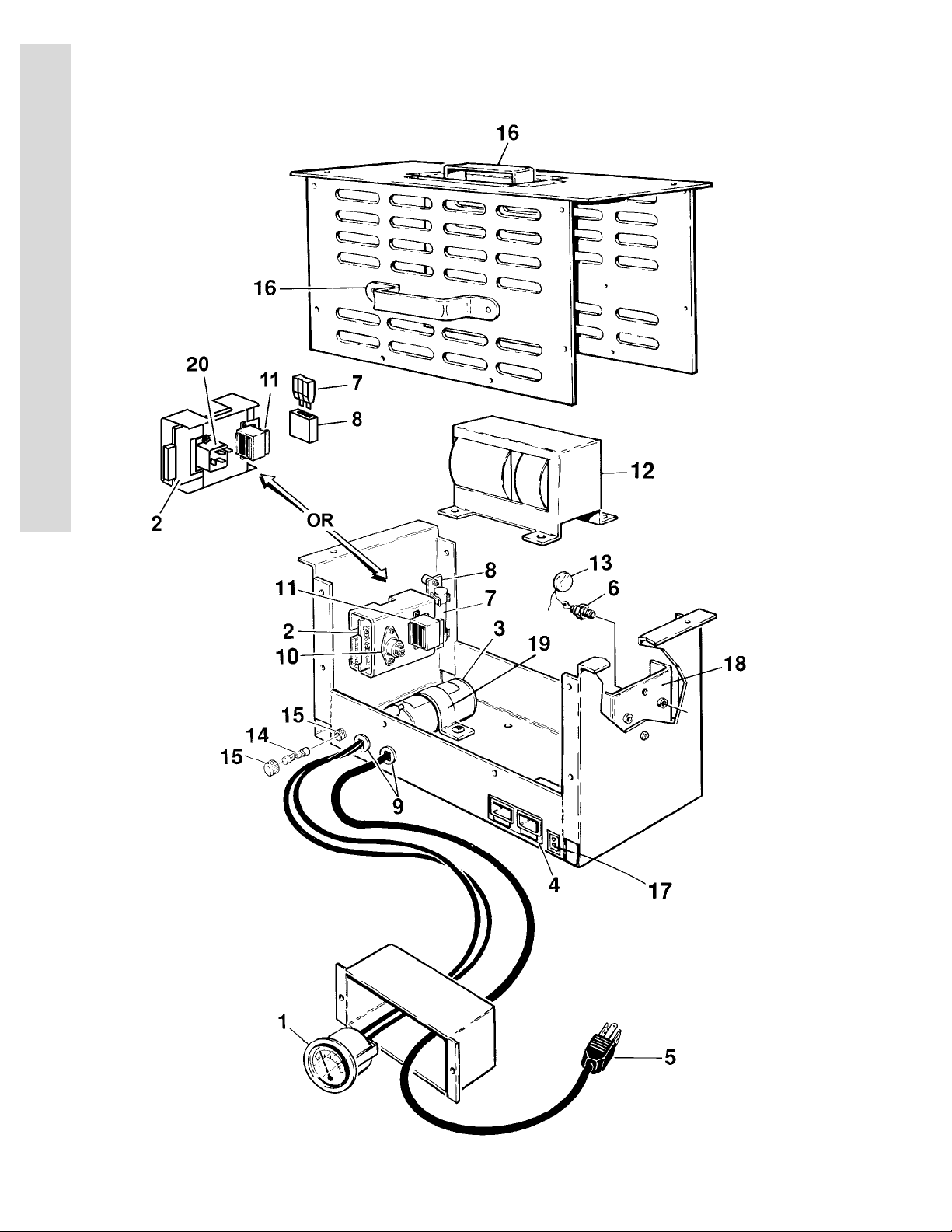
FIGURE 1-6. BATTERY CHARGER ASSEMBLY
FIG & ITEM # PART NUMBER DESCRIPTION QTY. REV.
BATTERY CHARGER ASSEMBLY Ref. A
0400102 Standard 110VAC/60HZ (Prior to S/N 60218) Ref. A
0400162 Standard 110VAC/60HZ (S/N 60218 to Present) Ref. A
0400124 UL 110VAC/60HZ (PRODUCTION) Ref.
0400124 UL 110VAC/60HZ (SERVICE REPLACEMENT) Ref.
0400103 Non-UL 220VAC/50HZ Ref.
0400137 UL 220VAC/50HZ Ref.
0400158 Non-UL 220VAC/60HZ (USA/CSA/LATIN AMERICA/
BRAZIL)
0400105 100VAC 50HZ/60HZ (JAPANESE SPEC) Ref.
Note: 0400124 Service Replacement Chargers Use a
Relay. 0400124 Production Chargers Use a Triac.
1 7011573 Ammeter 1
2 Board, Circuit Options: 1
Use 7011662 Prior to January 1995 (Was p/n 7011588) (0400102/
0400162/0400124 Production/0400103/0400137/
0400105 Chargers)
7011662 January 1995 to Present (0400102/0400162/0400124
Production/0400103/0400137/0400105 Chargers)
7022961 0400124 Service Replacement Charger
Use 7011679 All 0400158 Chargers (Was p/n 7018538)
3 Condenser Options: 1
7018500 0400102/0400124 Production/0400158/0400105
Chargers
7020624 0400124 Service Replacement/0400162 Chargers
7011623 0400103 Chargers
7011574 0400137 Chargers
4 7011590 Connector, DC 1
5 Cord, AC Options: 1
7011591 0400102/0400162/0400105 Chargers
7011643 0400124 Production Chargers
7022962 0400124 Service Replacement Chargers
7011544 0400103 Chargers
7011572 0400137 Chargers
7011677 0400158 Chargers
6 Diode Options: 2
7011576 0400102/0400124 Production/0400103/0400137/
0400105 Chargers
7011668 0400162/0400124 Service Replacement/0400158 Char-
gers
7 Fuse, DC Options: 1
7011593 0400102/0400162/0400124 Production/0400103/
0400137/0400105 Chargers
7020691 0400124 Service Replacement Chargers
7018570 0400158 Chargers
Ref.
—
—
—
—
—
—
S
E
C
T
I
O
N
1
F
R
A
M
E
3120769 1-19

SECTION 1 FRAME
S
E
C
T
I
O
N
1
F
R
A
M
E
FIGURE 1-6. BATTERY CHARGER ASSEMBLY (CONTINUED)
FIG & ITEM # PART NUMBER DESCRIPTION QTY. REV.
8 Holder, Fuse - DC Options: 1
7011594 0400102/0400162/0400124 Production/0400103/
0400137/0400105 Chargers
7018571 0400124 Service Replacement/0400158 Chargers
9 Connector, Strain Relief Options: A/R
7011528 0400102/0400124 Production/0400105 Chargers 3
7011646 0400124 Service Replacement/0400162 Chargers 2
7011646 0400103 Chargers (AC Cord) 2
7011528 0400103 Chargers (DC Cord) 1
7011528 0400137 Chargers 1
7011646 0400158 Chargers 1
7020659 0400124 Service Replacement Chargers (DC Cord) 1
10 Triac Options: 1
7011517 0400102/0400124 Production/0400103/0400137/
0400105 Chargers
7018572 0400162/0400158 Chargers
Not Required 0400124 Service Replacement Chargers
11 Transformer, Control Options: 1
7011518 0400102/0400162/0400124 Production/0400124
Service Replacement/0400105 Chargers
7011551 0400103/0400137/0400158 Chargers
12 Transformer, Main Options: 1
Use 7011595 0400102 Chargers (Was p/n 7011622)
7018574 0400162 Chargers
7011595 0400124 Production/0400105 Chargers
7022963 0400124 Service Replacement Chargers
7011598 0400103/0400137 Chargers
7018573 0400158 Chargers
13 Varistor Options: 1
7011596 0400102/0400105/0400124 Service Replacement Char-
gers
7011584 0400162/0400124 Production/0400124 Service
Replacement/0400103/0400137/0400158 Chargers
14 Fuse, AC Options: 1
7011597 0400102/0400105 Chargers
7011645 0400162/0400124 Production/0400124 Service Replace-
ment Chargers
7011508 0400103/0400137 Chargers
7018569 0400158 Chargers
15 7011507 Holder, Fuse - AC 1
16 Not Available Handle 2
17 7011621 Connector, Enable Switch 1
18 Heatsink Options: 1
7011610 0400102/0400103/0400137 Chargers
7018539 0400124 Service Replacement/0400162/0400158 Char-
gers
7011611 0400124 Production Chargers
7011628 0400105 Chargers
19 7011511 Strap, Condenser 1
20 7018506 Relay (0400124 Service Replacement Charger Only) 1
1-20 3120769

SECTION 1 FRAME
FIGURE 1-6. BATTERY CHARGER ASSEMBLY (CONTINUED)
FIG & ITEM # PART NUMBER DESCRIPTION QTY. REV.
21 7020687 Harness, Relay (0400124 Service Replacement Charger
Only - Not Shown)
1
S
E
C
T
I
O
N
1
F
R
A
M
E
3120769 1-21

SECTION 1 FRAME
S
E
C
T
I
O
N
1
F
R
A
M
E
FIGURE 1-7.BATTERY CHARGER ASSEMBLY - 220VAC/50HZ (SERVICE
REPLACEMENT)
1-22 3120769

SECTION 1 FRAME
.
FIGURE 1-7. BATTERY CHARGER ASSEMBLY - 220VAC/50HZ (SERVICE REPLACEMENT)
FIG & ITEM # PART NUMBER DESCRIPTION QTY. REV.
0400198 BATTERY CHARGER ASSEMBLY (SERVICE REPLACE-
MENT FOR 0400103 & 0400137 BATTERY CHARGERS)
1 Use 7011573 Ammeter (was p/n 7022915) 1
2 7022904 Cover Assembly, Case 1
3 7018525 Breaker, Circuit 1
4 7022938 Board, Circuit (was p/n 7022934) 1
5 7011621 Connector 1
6 7022914 Cord, AC 1
7 7022916 Cord, DC 1
8 7018577 Capacitor Assembly (Not Shown) 2
9 7011593 Fuse, DC - 45 Amp 1
10 7020658 Harness (Not Shown) 1
11 7011594 Holder, Fuse - DC 1
12 7011590 Connector, DC 1
13 7020649 Recifier Assembly 2
14 7020650 Recifier (1 Per Assembly) 1
15 7018563 Relay 1
16 7020674 Shunt Assembly 1
17 7011529 Strain Relief 1
7020659 Strain Relief 1
18 Use 7022939 Transformer (was p/n 7022917) 1
19 7020633 Varistor Assembly 1
Ref.
—
S
E
C
T
I
O
N
1
F
R
A
M
E
3120769 1-23
SECTION 1 FRAME
S
E
C
T
I
O
N
1
F
R
A
M
E
FIGURE 1-8.FRAME MOUNTED COMPONENTS INSTALLATION
1-24 3120769
 Loading...