


JLG 15AMI Parts Manual

3120876 15AMI 3
4 15AMI 3120876
3120876 15AMI 5


TABLE OF CONTENTS
SECTION 1 - BASE.............................................................................................................................................................................. 9
FIGURE 1-1. BASE MOUNTED COMPONENTS INSTALLATION - 15AMI ................................................................................... 10
SECTION 2 - CONTROLS ................................................................................................................................................................. 15
FIGURE 2-1. AC POWER COMPONENTS INSTALLATION (Prior to SN 0900027702) ................................................................ 16
FIGURE 2-2. AC POWER COMPONENTS INSTALLATION (SN 0900027702 to Present) ........................................................... 20
FIGURE 2-3. AC JUNCTION BOX ASSEMBLY ................................ ............................................................................................. 24
FIGURE 2-4. AC MOTOR/PUMP ASSEMBLY (FENNER) (Prior to SN 0900027702) ................................................................... 26
FIGURE 2-5. AC MOTOR/PUMP ASSEMBLY (MONARCH) (SN 0900027702 to Present) ........................................................... 30
FIGURE 2-6. DC POWER COMPONENTS INSTALLATION (Prior to SN 0900027391) ................................................................ 32
FIGURE 2-7. DC POWER COMPONENTS INSTALLATION (SN 0900027391 to Present) ........................................................... 36
FIGURE 2-8. DC MOTOR/PUMP ASSEMBLY (FENNER) (Prior to SN 0900027391) ................................................................... 40
FIGURE 2-9. DC MOTOR/PUMP ASSEMBLY (MONARCH) (SN 0900027391 to Present) ........................................................... 44
FIGURE 2-10. DC POWER PACK INSTALLATION (Prior to SN 0900031622) ............................................................................. 46
FIGURE 2-11. DC POWER PACK INSTALLATION (SN 0900031622 to Present) ......................................................................... 48
FIGURE 2-12. BATTERY CHARGER ASSEMBLY ........................................................................................................................ 50
FIGURE 2-13. CABLES AND CONTROLS INSTALLATION (Prior to SN 0900028708) ................................................................ 52
FIGURE 2-14. CABLES AND CONTROLS INSTALLATION (SN 0900028708 to Present) ............................................................ 56
SECTION 3 - MAST ........................................................................................................................................................................... 61
FIGURE 3-1. MAST ASSEMBLY (ALL CHAIN) .............................................................................................................................. 62
FIGURE 3-2. MAST MOUNTED COMPONENTS INSTALLATIONS .............................................................................................. 66
SECTION 4 - PLATFORM .................................................................................................................................................................. 69
FIGURE 4-1. MOLDED PLATFORM INSTALLATION .................................................................................................................... 70
FIGURE 4-2. QUICK-CHANGE PLATFORM INSTALLATION ....................................................................................................... 74
FIGURE 4-3. QUICK-CHANGE PLATFORM INSTALLATION WITH GULLWING GATE .............................................................. 78
FIGURE 4-4. QUICK-CHANGE PLATFORM INSTALLATION WITH SLIDE BAR.......................................................................... 82
FIGURE 4-5. QUICK-CHANGE PLATFORM INSTALLATION WITH EXTENSION........................................................................ 84
FIGURE 4-6. QUICK-CHANGE PLATFORM INSTALLATION WITH SLIDE BAR AND EXTENSION ........................................... 88
FIGURE 4-7. OPTIONAL PLATFORM COMPONENT INSTALLATIONS ...................................................................................... 92
SECTION 5 - CYLINDER ................................................................................................................................................................... 95
FIGURE 5-1. LIFT CYLINDER ASSEMBLY (Prior to SN 0900019526).......................................................................................... 96
FIGURE 5-2. LIFT CYLINDER ASSEMBLY (SN 0900019526 through 0900029965) .................................................................... 98
FIGURE 5-3. LIFT CYLINDER ASSEMBLY (SN 0900029966 to Present) ................................................................................... 100
SECTION 6 - HYDRAULIC .............................................................................................................................................................. 103
FIGURE 6-1. HYDRAULIC DIAGRAM (Prior to SN 0900027702) ................................................................................................ 104
FIGURE 6-2. HYDRAULIC DIAGRAM (SN 0900027702 to Present) ........................................................................................... 106
SECTION 7 - ELECTRICAL ............................................................................................................................................................. 109
FIGURE 7-1. ELECTRICAL DIAGRAM LIST ................................................................................................................................ 110
SECTION 8 - DECALS ..................................................................................................................................................................... 111
FIGURE 8-1. DECAL INSTALLATION (CE SPECS AND ALL AUSTRALIAN SPECS) (Prior to SN 0900022158) ...................... 112
FIGURE 8-2. DECAL INSTALLATIONS (CE SPECS) (SN 0900022158 to Present) ................................................................... 116
SECTION 9 - RECOMMENDED SERVICE PARTS STOCK ........................................................................................................... 119
FIGURE 9-1. 15AMI STANDARD PARTS .................................................................................................................................... 120
FIGURE 9-2. 15AMI VARIABLE PARTS ...................................................................................................................................... 122
SECTION 10 - SPECIAL OPTIONS ................................................................................................................................................. 123
FIGURE 10-1. SPECIAL OPTIONS .............................................................................................................................................. 124
PART NUMBER INDEX ................................................................................................................................................................... 125
3120876 15AMI 7


SECTION 1 - BASE
SECTION 1 - BASE
3120876 15AMI 9
SECTION 1 - BASE
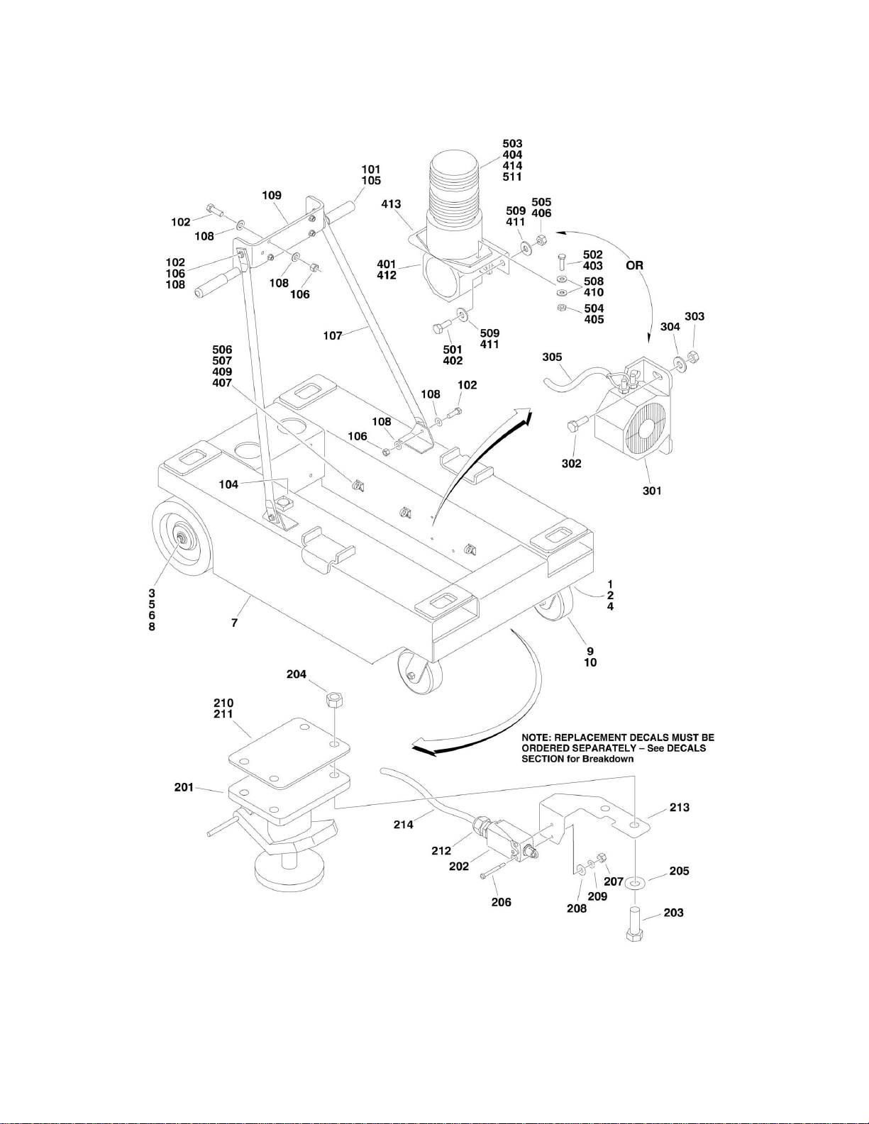
FIGURE 1-1. BASE MOUNTED COMPONENTS INSTALLATION - 15AMI
10 15AMI 3120876

SECTION 1 - BASE
ITEM
PART NUMBER
QTY
DESCRIPTION
REV
Ref
BASE ASSEMBLY OPTIONS:
0259524
Ref
Base Assembly (Prior to SN 0900019526)
A 0272231
Ref
Base Assembly (SN 0900019526 to Present)
C 1 0641607
8
Bolt 3/8in-16NC x 7/8in
2 3311605
8
Locknut 3/8in-16NC
3 3760348
2
Ring, Retainer
4 4711600
16
Flatwasher 3/8in
5 Ref
Flatwasher Options:
5 4712200
2
Flatwasher (Prior to SN 0900019526)
5 4740415
2
Flatwasher (SN 0900019526 to Present)
6 4740456
4
Washer, Shim
7 Ref
Base Weldment Options:
7 4846084
1
Base Weldment (Prior to SN 0900019526)
7 4846614
1
Base Weldment (SN 0900019526 to Present)
8 Ref
Wheel Assembly Options: (Stationary)
8 4860183
2
Wheel Assembly (Prior to SN 0900020796)
A 8 7020083
2
Wheel, Replacement
8 7020084
4
Bearing (2 Per Wheel)
8
4860246
2
Wheel Assembly (No Service Parts Available) (SN 0900020796
to Present)
B
9 Ref
Wheel Assembly Options:
9 Ref
Wheel Assembly - (Non-Locking) Options:
9
4860184
2
Wheel Assembly (Non-Locking Gray Tire and Wheel) (Prior
to SN 0900020877)
9 4860245
2
Wheel Assembly (Non-Locking Charcoal Gray Tire and Gray
Wheel) (SN 0900020877 to Present)
9
7020017
2
Swivel Rig for 4860184 (1 Per Assembly)
9 4860245
2
Swivel Rig for 4860245 (1 Per Assembly)
9 7020086
2
Wheel, Replacement for 4860184 (1 Per Assembly)
9 4860245
2
Wheel, Replacement for 4860245 (1 Per Assembly)
9 7020084
4
Bearing for 4860184 (2 Per Wheel)
9 4860245
4
Bearing for 4860245 (2 Per Wheel)
9 7012631
2
Bushing, Axle Spanner for 4860184 (1 Per Assembly)
9 4860245
2
Bushing, Axle Spanner for 4860245 (1 Per Assembly)
9 7012630
2
Axle Kit for 4860184 (1 Per Assembly)
9 4860245
2
Axle Kit for 4860245 (1 Per Assembly)
9 4860194
2
Wheel Assembly - (Locking)
A 9 7020017
2
Swivel Rig (1 Per Assembly)
9 7020086
2
Wheel, Replacement (1 Per Assembly)
9 7020084
4
Bearing (2 Per Wheel)
9 7012631
2
Bushing, Axle Spanner (1 Per Assembly)
9 7012630
2
Axle Kit (1 Per Assembly)
10
3020017
AR
Lubricant (Prior to SN 0900020796)
11
4240032
AR
Tie, Wire (Not Shown - 4in Long)
12
4460234
AR
Mount, Wire Tie (Not Shown)
Ref
MAST SUPPORT INSTALLATION OPTIONS:
0259483
Ref
Mast (All Cable) (Prior to SN 0900019526)
A 0272233
Ref
Mast (All Chain) (SN 0900019526 to Present)
B
101
0100001
AR
Adhesive
102
0641609
12
Bolt 3/8in-16NC x 1-1/8in
FIGURE 1-1. BASE MOUNTED COMPONENTS INSTALLATION - 15AMI
3120876 15AMI 11

ITEM
PART NUMBER
QTY
DESCRIPTION
REV
104
2420140
1
Gauge, Circular Level
105
2560088
2
Handle
106
Ref
Nut 3/8in-16NC Options:
106
3311605
AR
Locknut
106
3311608
AR
Locknut, Flanged
106
0100011
AR
Compound, Locking
107
Ref
Tube, Mast Brace Options:
107
4567824
2
Tube, Mast Brace (Prior to SN 0900031622)
107
4567508
2
Tube, Mast Brace (SN 0900031622 to Present)
108
4711600
AR
Flatwasher 3/8in Narrow
109
Ref
Support Weldment Options:
109
4845715
1
Support Weldment (Prior to SN 0900031622)
109
1001108178
1
Support Weldment (SN 0900031622 to Present)
110
1704582
1
Decal - Manual Descent (Not Shown - Located at bottom of Mast)
(SN 0900019526 to Present)
0259104
Ref
FLOOR STOP INSTALLATION
E
201
0920114
1
Stop, Floor
202
Ref
Limit Switch Options:
202
4360397
1
Limit Switch (Use p/n 4360456) (Prior to SN 0900013474)
202
4360456
1
Limit Switch (SN 0900013474 through 0900028054)
202
4360702
1
Limit Switch (SN 0900028055 to Present)
203
0641808
4
Bolt 1/2in-13NC x 1in
204
3311805
4
Locknut 1/2in-13NC
205
4711800
2
Flatwasher 1/2in
206
3911024
2
Screw #10-24NC x 1-1/2in
207
3311001
2
Nut #10-24NC
208
4751000
2
Flatwasher #10
209
4761000
2
Lockwasher #10
210
3539920
AR
Spacer - 11ga
211
3539921
AR
Spacer - 14ga
212
4460662
1
Strain Relief (Prior to SN 0900028055)
213
0902523
1
Bracket, Limit Switch
214
4922561
1
Harness, Brake
215
4460234
AR
Mount, Wire Tie (Not Shown)
216
4240033
AR
Tie, Wire (Not Shown)
0256808
Ref
DESCENT ALARM ONLY INSTALLATION (OPTIONAL)
C
301
0140033
1
Alarm 302
0641406
2
Bolt 1/4in-20NC x 3/4in
303
4751400
4
Flatwasher 1/4in
304
3311405
4
Nut 1/4in-20NC
305
4922805
1
Harness, Alarm (SN 0900023815 to Present)
1001107904
Ref
DESCENT ALARM AND BEACON LIGHT INSTALLATION
(OPTIONAL)
A
401
0140033
1
Alarm 402
0641406
2
Bolt 1/4in-20NC x 3/4in
403
0721006
2
Screw #10-24NC x 3/4in
404
2920146
1
Strobe Light Assembly
404
7016319
1
Bulb, Flash Tube
404
7016372
1
Replacement Lens
405
3311005
2
Locknut #10-24NC
406
3311405
4
Locknut 1/4in-20NC
407
4240032
AR
Tie-Strap
SECTION 1 - BASE
12 15AMI 3120876

SECTION 1 - BASE
ITEM
PART NUMBER
QTY
DESCRIPTION
REV
409
4460234
4
Base, Tie-Strap
410
4751000
4
Flatwasher #10 Regular
411
4751400
4
Flatwasher 1/4in Regular
412
4922805
1
Harness, Alarm
413
1001093322
1
Plate, Mounting
414
1001107934
1
Harness, Strobe Light
1001107903
Ref
BEACON LIGHT ONLY INSTALLATION (OPTIONAL)
A
501
0641406
2
Bolt 1/4in-20NC x 3/4in
502
0721006
2
Screw #10-24NC x 3/4in
503
2920146
1
Strobe Light Assembly
503
7016319
1
Bulb, Flash Tube
503
7016372
1
Replacement Lens
504
3311005
2
Locknut #10-24NC
505
3311405
4
Locknut 1/4in-20NC
506
4240032
AR
Tie-Strap
507
4460234
4
Base, Tie-Strap
508
4751000
4
Flatwasher #10 Regular
509
4751400
4
Flatwasher 1/4in Regular
510
1001093322
1
Plate, Mounting
511
1001107934
1
Harness, Strobe Light
3120876 15AMI 13


SECTION 2 - CONTROLS
SECTION 2 - CONTROLS
3120876 15AMI 15
SECTION 2 - CONTROLS
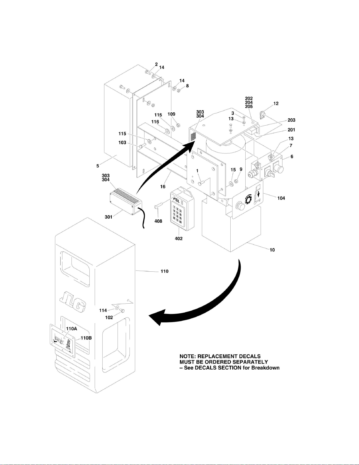
FIGURE 2-1. AC POWER COMPONENTS INSTALLATION (Prior to SN 0900027702)
16 15AMI 3120876

SECTION 2 - CONTROLS
ITEM
PART NUMBER
QTY
DESCRIPTION
REV
Ref
POWER PACK ASSEMBLY
0259207
Ref
220 VOLT (Prior to SN 0900019526)
A 0272239
Ref
220 VOLT (Specs) (SN 0900019526 through 0900027702)
C 1 0630486
4
Screw, Counter Sunk
2 0641406
4
Bolt 1/4in-20NC x 3/4in
3 0721006
2
Screw
5
0860936
1
Junction Box Assembly (See AC JUNCTION BOX ASSEMBLY
for Breakdown)
6 Ref
Ground Control Box Assembly Options:
6
0861212
NLA
Ground Control Box Assembly (Use p/n 0861305) (Prior to SN
0900020166)
6 0861305
1
Ground Control Box Assembly (SN 0900020166 through
0900027702)
Ref
Note: Original Equipment control box p/n 0861212 may
have been replaced with p/n 0861305 as a Service
Replacement. Identify component before ordering parts
6
7020078
1
Switch, Push-Pull (Stop)
6 7020096
1
Legend Plate, "Stop"
6 7020097
1
Legend Plate, "Power/Off/On"
6 Ref
Switch, Key Options:
6 7020098
1
Switch, Key (Prior to SN 0900020166)
6 4360467
1
Switch, Key (SN 0900020166 through 0900027702)
6 Ref
Key, Replacement Options:
6 7016339
1
Key, Replacement (Prior to SN 0900020166)
6
2860030
1
Key, Replacement (SN 0900020166 through
0900027702)
6 Ref
Connector, Strain Relief Options:
6 7020090
1
Connector, Strain Relief (Prior to SN 0900020166)
6
4460633
1
Connector, Strain Relief (SN 0900020166 through
0900023611)
6 7027787
1
Connector, Strain Relief (SN 0900023612 through
0900027702)
6
7020093
4
Screw m3 x 25
6 7020094
1
Lid 7
3311005
AR
Locknut #10-24NC
8 3311405
4
Locknut 1/4in-20NC
9 3311505
4
Locknut 5/16in-18NC
10 Ref
Pump/Motor Assembly Options:
10
3600265
1
Pump/Motor Assembly (Prior to SN 0900019526)
10
3600354
NLA
Pump/Motor Assembly (Use p/n 1001091459) (SN 0900019526
through 0900027701)
Ref
(Note: Kit p/n 1001091459 includes Pump/Motor Assy,
Pump and AC Box Mtg Brackets and 2 Hydraulic Tubes.
Once kit has been added, machine will be updated to S/N
0900027702 to S/N 0900029966 Design.)
12
4460566
1
Terminal, 90
13
4751000
AR
Flatwasher #10
14
4751400
8
Flatwasher 1/4in
15
4751500
4
Flatwasher 5/16in
16
4845712
1
Plate, Mounting
Ref
POWER PACK INSTALLATION
0259294
Ref
Power Unit (All Specs Except French Spec) (Prior to SN
A
FIGURE 2-1. AC POWER COMPONENTS INSTALLATION (Prior to SN 0900027702)
3120876 15AMI 17

ITEM
PART NUMBER
QTY
DESCRIPTION
REV
0900019526)
0259306
Ref
Power Unit (French Spec) (Prior to SN 0900019526)
A 0272235
Ref
Power Unit (SN 0900019526 through 0900027702)
B
102
0641404
4
Bolt 1/4in-20NC x 1/2in
103
0641614
4
Bolt 3/8in-16NC x 1-3/4in
104
1702353
1
Decal - Manual Descent (Prior to SN 0900019526)
109
3311605
4
Locknut 3/8in-16NC
110
Ref
Shield, Pump Cover Options:
110
4060875
1
Shield, Pump Cover (Prior to SN 0900019526)
110
4061024
1
Shield, Pump Cover (SN 0900019526 through 0900027702)
110A
1704582
1
Decal (SN 0900019688 through 0900027702)
110B
9984088
1
Cover (SN 0900019688 through 0900027702)
114
4711400
4
Flatwasher 1/4in Narrow
115
4711600
8
Flatwasher 3/8in Narrow
116
4070984
2
Shim, Pump Spacer
0273365
Ref
HOURMETER INSTALLATION (OPTIONAL)
D
201
2420172
1
Hourmeter
202
3311001
2
Nut #10-24NC
203
3572158
1
Bracket, Mounting
204
3911010
2
Screw #10-24NC x 5/8in
205
4761000
2
Lockwasher #10
206
4922935
1
Harness, Hourmeter (Not Shown)
0258482
Ref
AUXILIARY LOWERING INSTALLATION
A
301
0861213
1
Box, Power Down
301
0400181
2
Battery
301
4460320
1
Connector, Amp
301
4460267
2
Pin, Amp
303
4420064
0.3
ft/.09m
Velcro, Loop
304
4420065
0.3
ft/.09m
Velcro, Hook
0272686
Ref
SECURITY LOCK INSTALLATION
C
401
2820035
8 in/20cm
Sleeve, Insulation (Not Shown)
402
2940132
1
Lock, Programmable
408
0791003
2
Screw#10-24NC x 3/8in
SECTION 2 - CONTROLS
18 15AMI 3120876

SECTION 2 - CONTROLS
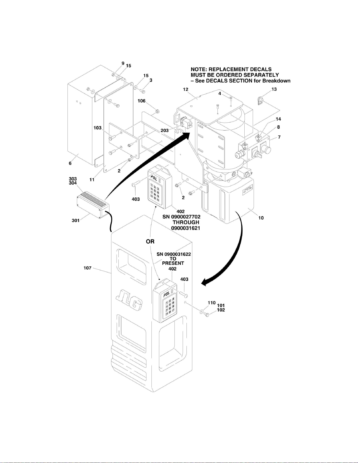
FIGURE 2-2. AC POWER COMPONENTS INSTALLATION (SN 0900027702 to Present)
20 15AMI 3120876

SECTION 2 - CONTROLS
ITEM
PART NUMBER
QTY
DESCRIPTION
REV
0275889
Ref
POWER PACK ASSEMBLY
D 2 0630550
2
Bolt 1/4in-20NC x 3/4in
3 0641406
4
Bolt 1/4in-20NC x 3/4in
4 0721006
2
Screw 5
0791609
2
Bolt 3/8in-16NC x 1-1/8in
6
0860936
1
Junction Box Assembly (See AC JUNCTION BOX ASSEMBLY for
Breakdown)
7
0861305
1
Ground Control Box Assembly
7 7020078
1
Switch, Push-Pull (Stop)
7 7020096
1
Legend Plate, "Stop"
7 7020097
1
Legend Plate, "Power/Off/On"
7 4360467
1
Switch, Key
7 2860030
1
Key, Replacement
7 7027787
1
Connector, Strain Relief
7 7020093
4
Screw M3 x 25
7 7020094
1
Lid 8
3311005
2
Locknut #10-24NC
9 3311405
4
Locknut 1/4in-20NC
10
3600467
1
Pump/Motor Assembly (See AC MOTOR/PUMP ASSEMBLY
(MONARCH) for Breakdown)
11
4341431
1
Mounting, Bracket AC Box
12
4341432
1
Mounting, Bracket Pump
13
4460566
1
Terminal, 90
14
4751000
2
Flatwasher #10
15
4751400
8
Flatwasher 1/4in
16 Ref
Shrink, Heat Options (Not Shown):
16
2820030
1 ft/0.3m
Shrink, Heat (SN 0900027702 through 0900030160)
16
1001105113
2
Shrink, Heat (SN 0900030161 to Present)
0275939
Ref
POWER PACK INSTALLATION
B
101
0100011
AR
Compound, Locking
102
0641404
4
Bolt 1/4in-20NC x 1/2in
103
0791609
4
Bolt 3/8in-16NC x 1-1/8in
106
3311608
4
Nut 3/8in-16NC
107
4061024
1
Shield, Pump Cover
110
4711400
4
Flatwasher 1/4in Narrow
0275697
Ref
HOURMETER INSTALLATION (OPTIONAL)
C
203
2420172
1
Hourmeter
205
4922935
1
Harness, Hourmeter (Not Shown)
0258482
Ref
AUXILIARY LOWERING INSTALLATION
A
301
0861213
1
Box, Power Down
301
0400181
2
Battery
301
4460320
1
Connector, Amp
301
4460267
2
Pin, Amp
303
4420064
0.3
ft/.09m
Velcro, Loop
304
4420065
0.3
ft/.09m
Velcro, Hook
Ref
SECURITY LOCK INSTALLATION
0272686
Ref
Security Lock Installation (SN 0900026490 through
0900031621)
D
1001110217
Ref
Security Lock Installation (SN 0900031622 to Present)
B
FIGURE 2-2. AC POWER COMPONENTS INSTALLATION (SN 0900027702 to Present)
3120876 15AMI 21

ITEM
PART NUMBER
QTY
DESCRIPTION
REV
401
2820035
8 in/20cm
Sleeve, Insulation (Not Shown)
402
2940132
1
Lock, Programmable (Note: Does not Include Items 404 & 405)
403
Ref
Fastener Options:
403
0791003
2
Screw #10-24NC x 3/8in
403
3820032
2
Rivet
404
4460267
3
Pin, Male (Not Shown) (SN 0900031622 to Present)
405
4460326
1
Plug, Male - 3 Position (Not Shown) (SN 0900031622 to
Present)
406
1001114375
1
Harness, Security Lock (Not Shown) (SN 0900031622 to
Present)
406
4460268
3
Socket, Female (Not Shown) (SN 0900031622 to Present)
406
4460445
1
Receptacle, Female - 3 Position (Not Shown) (SN 0900031622
to Present)
SECTION 2 - CONTROLS
22 15AMI 3120876

SECTION 2 - CONTROLS
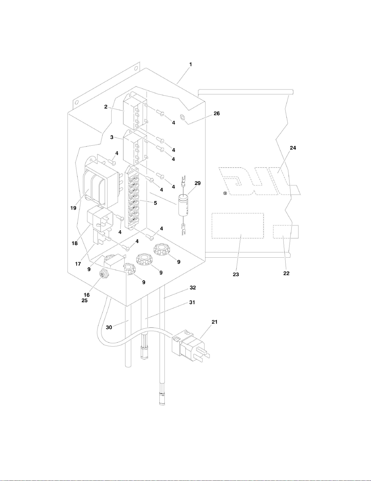
FIGURE 2-3. AC JUNCTION BOX ASSEMBLY
24 15AMI 3120876

SECTION 2 - CONTROLS
ITEM
PART NUMBER
QTY
DESCRIPTION
REV
Ref
JUNCTION BOX ASSEMBLY
0860936
Ref
220 VOLT
K 1 0860943
1
Box with Lid
2 3740094
2
Relay, Starter 12 VDC
3 3740105
1
Relay, Starter
4 3910808
10
Screw #8-32NF x 1/2in
5 4460565
1
Strip, Terminal
9 4460633
4
Connector, Strain Relief
16
4360070
2
Circuit Breaker - 15amp
17
4360376
1
Rectifier
18
3740049
1
Relay 19 Ref
Transformer Options:
19
4530010
1
Transformer (Prior to SN 0900014643)
19
4530013
1
Transformer (SN 0900014643 through 0900028707)
19
4530010
1
Transformer (SN 0900028708 to Present)
21 Ref
Harness Options:
21
1060585
3 ft/0.9m
Harness (Prior to SN 0900023728)
21
4923152
1
Harness (SN 0900023728 to Present)
22
1702103
1
Decal 23
1702120
1
Decal - Wire Size
24 Ref
Decal - JLG Options:
24
1702365
1
Decal - JLG (Prior to SN 0900028708)
24
1703681
1
Decal - JLG (SN 0900028708 to Present)
25
3520028
1
Plug 1/2 (SN 0900013477 to Present)
26
3520034
4
Plug, Hole (SN 0900019636 to Present)
27
4923151
1
Harness, AC Box (Not Shown) (SN 0900020166 to Present)
28
4933310
1
Wiring Diagram, AC Box (Not Shown - See ELECTRICAL
SECTION) (SN 0900020166 to Present)
29
1001093646
1
Harness, Capacity 2200UF 50V (SN 0900028708 to Present)
30
4922546
1
Harness, Ground Controls (SN 0900019526 to Present)
I
30
4460424
1
Terminal, Plug
30
4460268
2
Socket, Female
31
1001096586
1
Harness, 16/5
A
31
1060687
1 ft/0.3m
Cable Electrical 16/5
32
1001096587
1
Harness, 12/3
A
32
1060908
2.42
ft/0.8m
Cable Electrical 12/3
FIGURE 2-3. AC JUNCTION BOX ASSEMBLY
3120876 15AMI 25
SECTION 2 - CONTROLS
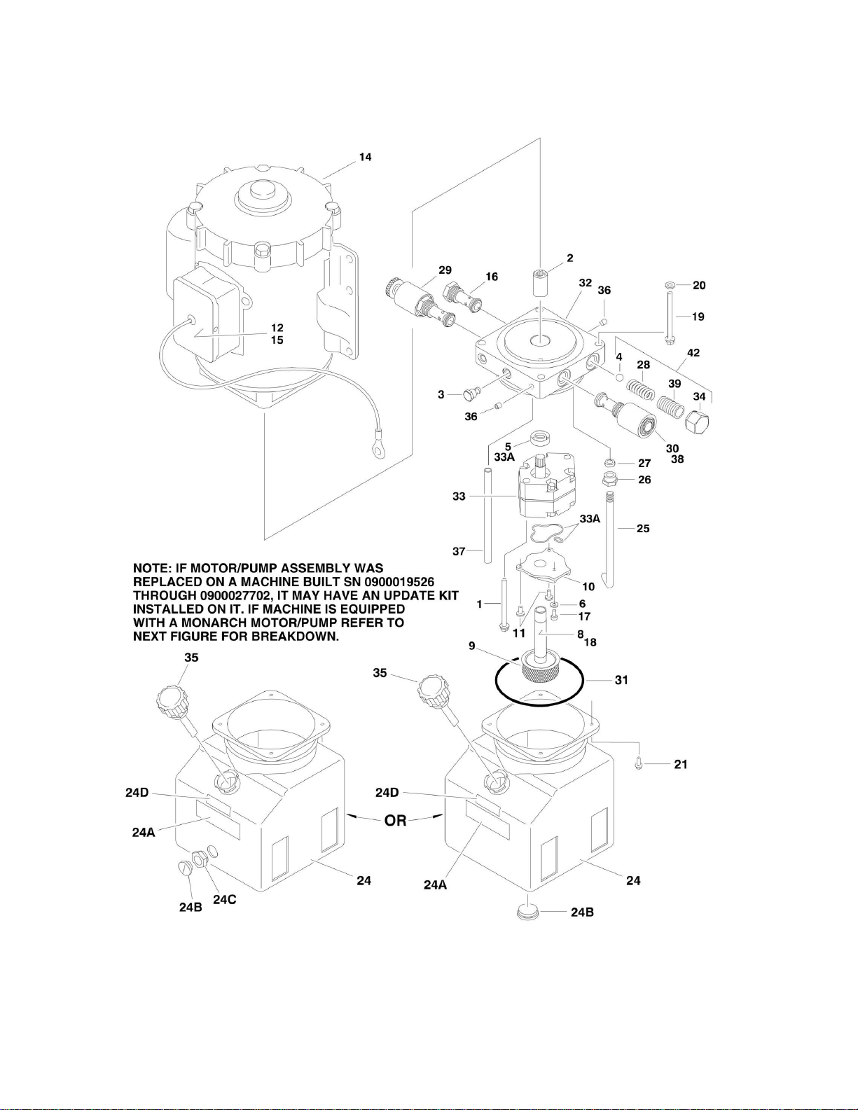
FIGURE 2-4. AC MOTOR/PUMP ASSEMBLY (FENNER) (Prior to SN 0900027702)
26 15AMI 3120876

SECTION 2 - CONTROLS
ITEM
PART NUMBER
QTY
DESCRIPTION
REV
Ref
NOTE: IF MOTOR/PUMP ASSEMBLY WAS REPLACED ON A
MACHINE BUILT S/N 0900019526 to S/N 0900027702, IT MAY
HAVE AN UPDATE KIT INSTALLED ON IT. IF MACHINE IS
EQUIPPED WITH A MONARCH MOTOR/PUMP REFER TO NEXT
FIGURE FOR BREAKDOWN.
Ref
MOTOR/PUMP ASSEMBLY
3600265
Ref
220 Volt (Prior to SN 0900019526)
A 3600354
Ref
220 Volt (SN 0900019526 through 0900027702)
C 1 7013713
2
Bolt 5/16in-24NF x 2 3/4in
2 7016735
1
Coupling
3 7013714
1
Plug 4
7013779
1
Ball (Was p/n 7013715)
5 7013716
1
Seal (Part of Pump Seal Kit p/n 7013701)
6 7013717
1
Washer
8 7013722
1
Magnet
9 7013723
1
Filter 10
7013727
1
Cover 11
7013728
2
Screw
12 Ref
Gasket Options:
12
7016787
1
Gasket for 3600354 Assemblies (was p/n 7016793 - See Item
15 Note)
12
7013751
1
Gasket for 3600265 Assemblies
14 Ref
Motor Options:
14
7013732
1
220 Volt (Prior to SN 0900019526)
14
7016774
1
220 Volt (SN 0900019526 through 0900027702)
15 Ref
Switch Box Component Options:
15
7016787
1
Timer Relay Assembly (Includes Relay, Wiring, Box, Item 12
Gasket and Hardware for 3600354 Assemblies
Ref
Note: Individual Pieces No Longer Available. Must
Purchase Complete Assembly.
15
7013751
1
Timer Relay Assembly (Includes Relay, Wiring, Box, Item 12
Gasket and Hardware for 3600265 Assemblies
Ref
Note: Individual Pieces No Longer Available. Must
Purchase Complete Assembly.
16
7013708
1
Cartridge, Valve - Check
17
3931516
1
Bolt 5/16in-18NC x 1in
18
7016756
1
Pipe, Plumbing
19
7016757
4
Bolt M6-1.0 35MM
20
7016758
4
Lockwasher 1/4in
21
7016721
4
Bolt #12-24NC x 1/2in
24 Ref
Tank Options:
24
7016760
1
Tank Used (Prior to SN 0900019526)
24
7022219
1
Tank Used (SN 0900019526 through 0900027702)
24A
7013748
1
Decal - Caution
24B
7016759
1
Plug
24C
7016777
1
Fitting, Coupling
24D
7022223
1
Decal - Fill Line
25
7016761
1
Tube, Return
26
7013792
1
Nut, Tube Compression
27
7013793
1
Sleeve, Tube Compression
28
7013779
1
Spring, Green (was p/n 7016762)
29 Ref
Cartridge, Valve - Manual Descent Options:
FIGURE 2-4. AC MOTOR/PUMP ASSEMBLY (FENNER) (Prior to SN 0900027702)
3120876 15AMI 27

ITEM
PART NUMBER
QTY
DESCRIPTION
REV
29
7013764
1
Cartridge, Valve - Manual Descent (Prior to SN 0900019526)
29
Not Required
0
Cartridge, Valve - Manual Descent (Moved to Lift Cylinder) (SN
0900019526 through 0900027702)
30
7016751
1
Coil, Solenoid
31
7013743
1
O-Ring
32 Ref
End Head Options:
32
See Note
1
End Head (was p/n 7016753) (Note: No Longer Available)
(Prior to SN 0900019526)
32
7022220
1
End Head (SN 0900019526 through 0900027702)
33
7016717
1
Pump Assembly
33A
7013701
1
Seal Kit - Pump (Includes Gasket for Item #10 Cover, O-Ring
and #5 Seal)
34
7013779
1
Cap, Relief (Was p/n 7013750)
35 Ref
Breather Options:
35
7013794
1
Breather (Prior to SN 0900019526)
35
7016714
1
Breather (SN 0900019526 through 0900027702)
36 Ref
Plug Options:
36
7013720
2
Plug (Prior to SN 0900019526)
36
Not Required
0
Plug (SN 0900019526 through 0900027702)
37 Ref
Tube, Return Options:
37
7013763
1
8in Length (Prior to SN 0900019526)
37
7022224
1
8-1/2in Length (SN 0900019526 through 0900027702)
38
7016755
1
Cartridge, Valve without Coil
39
7013779
1
Screw, Adjustment (was p/n 7013770)
40
7013745
1
Decal, Motor 50/60 Hertz (Not Shown)
42
7013779
1
Relief Valve Kit (Includes Items 4, 28, 34 & 39)
SECTION 2 - CONTROLS
28 15AMI 3120876

SECTION 2 - CONTROLS
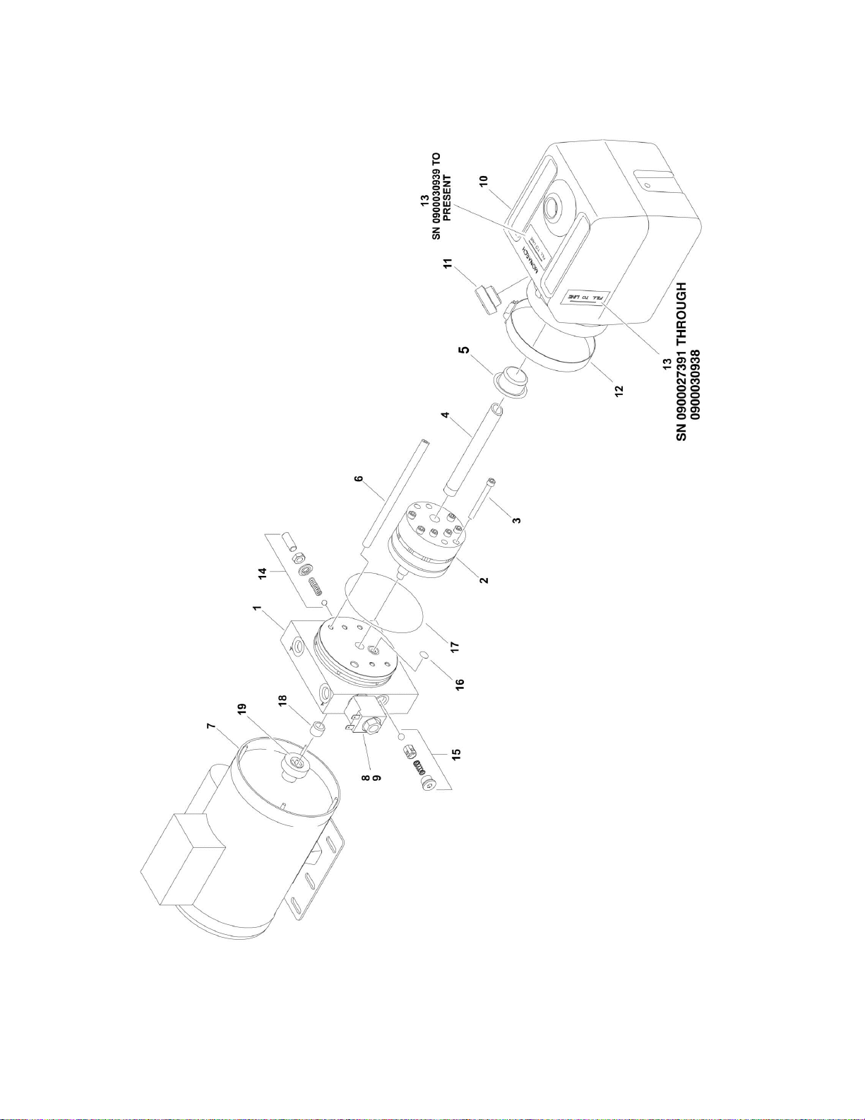
FIGURE 2-5. AC MOTOR/PUMP ASSEMBLY (MONARCH) (SN 0900027702 to Present)
30 15AMI 3120876
 Loading...