


JLG 45ic Parts Manual
Illustrated Parts Manual
Models
40ic
45ic
P/N
3120853
September 30 2011


REVISION LOG
August 1, 1996 - Original Issue of Manual
August 15, 1997 - Revised Manual
December 1, 2000 - Revised Manual (Edited to B/M 0010531 Revision 21 & B/M 0010530 Revision 22)
August 16, 2005 - Revised Manual
January 31, 2008 - Revised Manual
September 30, 2011 - Revised Manual
3120853 A

REVISION LOG
B 3120853

TABLE OF CONTENTS
FIGURE NO. TITLE PAGE NO.
SECTION 1 -FRAME..............................................................................................................1-1
1-1 FRAME AND STEERING INSTALLATIONS . . . . . . . . . . . . . . . . . . . . . . . . . . . . . . . . . . .1-2
1-2 TIRE AND WHEEL DRIVE INSTALLATIONS.. . . . . . . . . . . . . . . . . . . . . . . . . . . . . . . . . .1-6
1-3 DRIVE HUB ASSEMBLY. . . . . . . . . . . . . . . . . . . . . . . . . . . . . . . . . . . . . . . . . . . . . . . . . .1-10
1-4 DRIVE MOTOR ASSEMBLY. . . . . . . . . . . . . . . . . . . . . . . . . . . . . . . . . . . . . . . . . . . . . . .1-12
1-5 DRIVE BRAKE ASSEMBLY. . . . . . . . . . . . . . . . . . . . . . . . . . . . . . . . . . . . . . . . . . . . . . . .1-14
1-6 VALVES, BATTERY AND TILT INDICATOR INSTALLATIONS (FRAME MOUNTED). . . .1-18
1-7 ACCESSORY VALVE ASSEMBLY.. . . . . . . . . . . . . . . . . . . . . . . . . . . . . . . . . . . . . . . . . .1-22
1-8 VANGUARD GAS ENGINE INSTALLATIONS. . . . . . . . . . . . . . . . . . . . . . . . . . . . . . . . . .1-24
1-9 DUAL FUEL INSTALLATION (OPTION FOR VANGUARD GAS MACHINES). . . . . . . . .1-30
1-10 YANMAR DIESEL ENGINE INSTALLATION. . . . . . . . . . . . . . . . . . . . . . . . . . . . . . . . . . .1-34
1-11 PISTON PUMP ASSEMBLY. . . . . . . . . . . . . . . . . . . . . . . . . . . . . . . . . . . . . . . . . . . . . . .1-38
1-12 GEAR PUMP ASSEMBLY. . . . . . . . . . . . . . . . . . . . . . . . . . . . . . . . . . . . . . . . . . . . . . . . .1-40
1-13 TANK INSTALLATIONS . . . . . . . . . . . . . . . . . . . . . . . . . . . . . . . . . . . . . . . . . . . . . . . . . .1-42
1-14 FRAME COVERS INSTALLATIONS. . . . . . . . . . . . . . . . . . . . . . . . . . . . . . . . . . . . . . . . .1-44
SECTION 2 -TURNTABLE................................................................................................... 2-1
2-1 TURNTABLE MOUNTED COMPONENTS INSTALLATION. . . . . . . . . . . . . . . . . . . . . . .2-2
2-2 CONTROL VALVE ASSEMBLY. . . . . . . . . . . . . . . . . . . . . . . . . . . . . . . . . . . . . . . . . . . . .2-6
2-3 SWING DRIVE AND TURNTABLE BEARING INSTALLATIONS. . . . . . . . . . . . . . . . . . . .2-8
2-4 SWING MOTOR ASSEMBLY. . . . . . . . . . . . . . . . . . . . . . . . . . . . . . . . . . . . . . . . . . . . . .2-10
2-5 GROUND CONTROL COMPONENTS INSTALLATION. . . . . . . . . . . . . . . . . . . . . . . . . .2-12
2-6 TURNTABLE AND HOODS INSTALLATIONS.. . . . . . . . . . . . . . . . . . . . . . . . . . . . . . . . .2-16
SECTION 3 -BOOM............................................................................................................. 3-1
3-1 BOOM AND LIMIT SWITCHES INSTALLATIONS.. . . . . . . . . . . . . . . . . . . . . . . . . . . . . .3-2
3-2 MAIN BOOM COMPONENTS ASSEMBLY. . . . . . . . . . . . . . . . . . . . . . . . . . . . . . . . . . . .3-6
SECTION 4 -PLATFORMS................................................................................................... 4-1
4-1 PLATFORM COMPONENTS INSTALLATION.. . . . . . . . . . . . . . . . . . . . . . . . . . . . . . . . .4-2
4-2 ROTATOR MOTOR/PUMP/TANK ASSEMBLY. . . . . . . . . . . . . . . . . . . . . . . . . . . . . . . . .4-6
4-3 PLATFORM CONSOLE ASSEMBLY. . . . . . . . . . . . . . . . . . . . . . . . . . . . . . . . . . . . . . . . .4-8
4-4 CONTROLLER ASSEMBLY - DRIVE/STEER. . . . . . . . . . . . . . . . . . . . . . . . . . . . . . . . . .4-12
SECTION 5 -CYLINDER...................................................................................................... 5-1
5-1 UPPER LIFT CYLINDER ASSEMBLIES. . . . . . . . . . . . . . . . . . . . . . . . . . . . . . . . . . . . . .5-2
5-2 MID LIFT CYLINDER ASSEMBLIES. . . . . . . . . . . . . . . . . . . . . . . . . . . . . . . . . . . . . . . . .5-4
5-3 LOWER LIFT CYLINDER ASSEMBLIES. . . . . . . . . . . . . . . . . . . . . . . . . . . . . . . . . . . . . .5-8
5-4 MASTER CYLINDER ASSEMBLY. . . . . . . . . . . . . . . . . . . . . . . . . . . . . . . . . . . . . . . . . . .5-12
5-5 PLATFORM ROTATOR CYLINDER ASSEMBLY.. . . . . . . . . . . . . . . . . . . . . . . . . . . . . . .5-14
5-6 SLAVE (PLATFORM LEVEL) CYLINDER ASSEMBLY. . . . . . . . . . . . . . . . . . . . . . . . . . .5-16
5-7 STEER CYLINDER ASSEMBLY . . . . . . . . . . . . . . . . . . . . . . . . . . . . . . . . . . . . . . . . . . . .5-18
5-8 TELESCOPE CYLINDER ASSEMBLIES. . . . . . . . . . . . . . . . . . . . . . . . . . . . . . . . . . . . . .5-20
5-9 OPTIONAL CYLINDER BELLOWS INSTALLATION. . . . . . . . . . . . . . . . . . . . . . . . . . . . .5-22
SECTION 6 -HYDRAULICS.................................................................................................. 6-1
6-1 HYDRAULIC DIAGRAM LIST . . . . . . . . . . . . . . . . . . . . . . . . . . . . . . . . . . . . . . . . . . . . . .6-2
6-2 HYDRAULIC DIAGRAM . . . . . . . . . . . . . . . . . . . . . . . . . . . . . . . . . . . . . . . . . . . . . . . . . .6-8
6-3 HYDRAULIC DIAGRAM - MANUAL ASCENT (DUTCH AND GERMAN SPEC). . . . . . . .6-10
3120853 i

TABLE OF CONTENTS (CONTINUED)
FIGURE NO. TITLE PAGE NO.
SECTION 7 -ELECTRICAL.................................................................................................. 7-1
7-1 ELECTRICAL DIAGRAMS AND DIAGRAM LIST.. . . . . . . . . . . . . . . . . . . . . . . . . . . . . . .7-2
7-2 ELECTRICAL SCHEMATIC.. . . . . . . . . . . . . . . . . . . . . . . . . . . . . . . . . . . . . . . . . . . . . . .7-4
7-3 HARNESS INSTALLATIONS . . . . . . . . . . . . . . . . . . . . . . . . . . . . . . . . . . . . . . . . . . . . . . 7-8
SECTION 8 -DECALS ......................................................................................................... 8-1
8-1 DECALS INSTALLATION. . . . . . . . . . . . . . . . . . . . . . . . . . . . . . . . . . . . . . . . . . . . . . . . . 8-2
SECTION 9 -RECOMMENDED SERVICE PARTS STOCK ................................................ 9-1
SECTION 10 -SPECIAL OPTIONS.................................................................................... 10-1
ii 3120853

SECTION 1 FRAME
S
E
TABLE OF CONTENTS
FIGURE DESCRIPTION PAGE
1-1 FRAME AND STEERING INSTALLATIONS. . . . . . . . . . . . . . . . . . . . . . . . . . . . . . . . . . . . . . . 1-2
1-2 TIRE AND WHEEL DRIVE INSTALLATIONS. . . . . . . . . . . . . . . . . . . . . . . . . . . . . . . . . . . . . . 1-6
1-3 DRIVE HUB ASSEMBLY. . . . . . . . . . . . . . . . . . . . . . . . . . . . . . . . . . . . . . . . . . . . . . . . . . . . . . 1-10
1-4 DRIVE MOTOR ASSEMBLY. . . . . . . . . . . . . . . . . . . . . . . . . . . . . . . . . . . . . . . . . . . . . . . . . . . 1-12
1-5 DRIVE BRAKE ASSEMBLY. . . . . . . . . . . . . . . . . . . . . . . . . . . . . . . . . . . . . . . . . . . . . . . . . . . . 1-14
1-6 VALVES, BATTERY AND TILT INDICATOR INSTALLATIONS (FRAME MOUNTED). . . . . . . . 1-18
1-7 ACCESSORY VALVE ASSEMBLY.. . . . . . . . . . . . . . . . . . . . . . . . . . . . . . . . . . . . . . . . . . . . . . 1-22
1-8 VANGUARD GAS ENGINE INSTALLATIONS. . . . . . . . . . . . . . . . . . . . . . . . . . . . . . . . . . . . . . 1-24
1-9 DUAL FUEL INSTALLATION (OPTION FOR VANGUARD GAS MACHINES). . . . . . . . . . . . . 1-30
1-10 YANMAR DIESEL ENGINE INSTALLATION. . . . . . . . . . . . . . . . . . . . . . . . . . . . . . . . . . . . . . . 1-34
1-11 PISTON PUMP ASSEMBLY. . . . . . . . . . . . . . . . . . . . . . . . . . . . . . . . . . . . . . . . . . . . . . . . . . . 1-40
1-12 GEAR PUMP ASSEMBLY . . . . . . . . . . . . . . . . . . . . . . . . . . . . . . . . . . . . . . . . . . . . . . . . . . . . 1-42
1-13 TANK INSTALLATIONS . . . . . . . . . . . . . . . . . . . . . . . . . . . . . . . . . . . . . . . . . . . . . . . . . . . . . . 1-44
C
T
I
O
N
1
F
R
A
M
E
1-14 FRAME COVERS INSTALLATIONS. . . . . . . . . . . . . . . . . . . . . . . . . . . . . . . . . . . . . . . . . . . . . 1-46
3120853 1-1
S
SECTION 1 FRAME
E
C
T
I
O
N
1
F
R
A
M
E
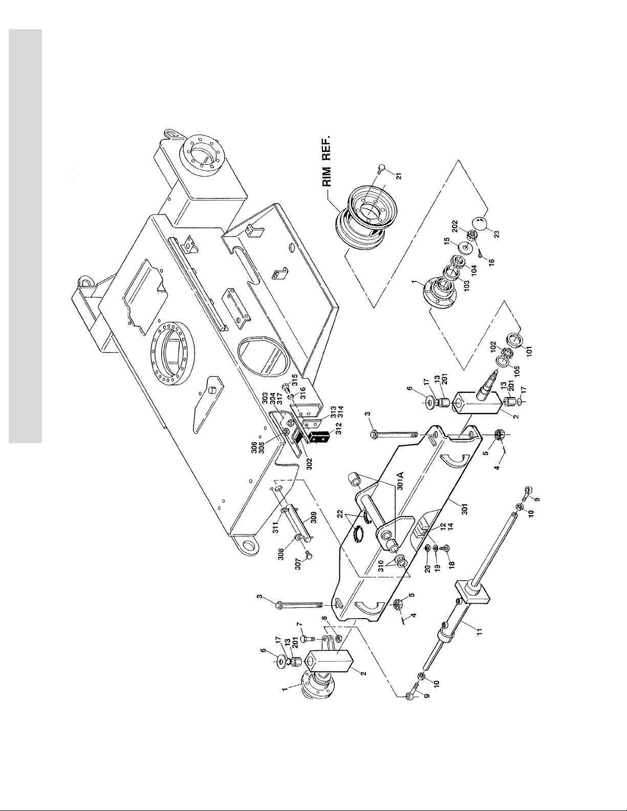
FIGURE 1-1. FRAME AND STEERING INSTALLATIONS.
1-2 3120853

SECTION 1 FRAME
FIGURE 1-1. FRAME AND STEERING INSTALLATIONS.
FIG & ITEM # PART NUMBER DESCRIPTION QTY. REV.
FRAME WELDMENT OPTIONS: 1
2360402 Model 40ic
2360403 Model 45ic
S
E
C
T
I
O
0256855 STEERING AND SPINDLES INSTALLATION Ref. –/3
1 2780201 Hub Assembly (See Items 101-105 for Breakdown) 2
2 4130319
3 3421988 Kingpin 2
4 3450810 Pin, Cotter 1/4" x 2 1/3" 2
5 3313003 Nut, Slotted 1 1/4 -7NC 2
6 0440162 Washer, Thrust 2
7 0642016 Bolt 5/8"-11NC x 2" 2
8 3312005 Locknut 5/8"-11NC 2
9 3841146 End, Rod 2
10 3322002 Nut, Jam 5/8"-18NF 2
11 Use 1683698
12 3340644 Pad, Wear 1
13 3020022 Grease A/R
14 4070809 Shim A/R
15 4712400 Flatwasher 7/8" 2
16 3450506 Pin, Cotter 2
17 3780182 O-Ring 4
18 0641510 Bolt 5/16"-18NC x 1 1/4" 1
19 4751500 Flatwasher 5/16" 1
20 3311505 Locknut 5/16"-18NC 1
21 0630016 Bolt, Wheel 1/2"-20NF x 1" 12
22 4060808 Trim 2 Ft/.61m
23 1120457 Cap, Dust 2
Spindle Weldment (See Items 201-202 for
Breakdown)
Steer Cylinder Assembly (See Section 5 for
Breakdown) (Was P/N 1683487 Prior to S/N 37950)
2
1
N
1
F
R
A
M
E
2780201 HUB ASSEMBLY Ref. D
101 Kit Cup, Bearing - Inner (1 Per Hub) 2
102 Kit Cone, Bearing - Inner (1 Per Hub) 2
103 Kit Cup, Bearing - Outer (1 Per Hub) 2
104 Kit Cone, Bearing - Outer (1 Per Hub) 2
105 Kit Seal (1 Per Hub) 2
– – – – – – – – – –
2900842 Bearing Kit (Includes Item 101-105) 2
SPINDLE ASSEMBLY Ref.
201 0961621 Bushing (2 Per Spindle) 4
202 3322403 Nut, Slotted 7/8"-14NF (1 Per Spindle) 2
3120853 1-3

S
E
C
T
I
O
N
1
F
R
A
M
E
SECTION 1 FRAME
FIGURE 1-1. FRAME AND STEERING INSTALLATIONS. (CONTINUED)
FIG & ITEM # PART NUMBER DESCRIPTION QTY. REV.
0253613 AXLE INSTALLATION Ref. D
301 4844324 Axle Weldment (Includes Item 301A) 1
301A 0961621 Bushing 2
302 0940048 Bumper 2
303 4070832 Shim 1/2"-13mm A/R
304 4070833 Shim 1/16"-1.6mm A/R
305 0641814 Bolt 1/2"-13NC x 1 3/4" 4
306 3311805 Locknut 1/2"-13NC 4
307 0641608 Bolt 3/8"-16NC x 1" 1
308 3841143 Pin, Keeper 1
309 3422170 Pin, Axle 1
310 4740247 Washer, Thrust 2
311 3451210 Pin, Cotter 3/8" x 2 1/2" 1
312 3340450 Pad, Wear 2
313 4070834 Shim 1/4"-6.4mm A/R
314 4070835 Shim 1/16"-1.6mm A/R
315 0641610 Bolt 3/8"-16NC x 1 1/4"" 4
316 4751600 Flatwasher 3/8" 4
317 4070853 Shim 1/32"-.8mm A/R
– – – – – – – – – – –
0100011 Loctite #242 (Not Shown) A/R
1-4 3120853

SECTION 1 FRAME
S
FIGURE 1-1. FRAME AND STEERING INSTALLATIONS. (CONTINUED)
FIG & ITEM # PART NUMBER DESCRIPTION QTY. REV.
E
C
T
I
O
N
1
F
R
A
M
E
3120853 1-5

S
SECTION 1 FRAME
E
C
T
I
O
N
1
F
R
A
M
E
FIGURE 1-2. TIRE AND WHEEL DRIVE INSTALLATIONS.
1-6 3120853

SECTION 1 FRAME
FIGURE 1-2. TIRE AND WHEEL DRIVE INSTALLATIONS.
FIG & ITEM # PART NUMBER DESCRIPTION QTY. REV.
0255994 WHEEL DRIVE INSTALLATION Ref. A
1 2780219 Drive Hub Assembly (See Figure 1-3 For Breakdown) 2
2 3160158
3 0920084
4 3321801 Nut 1/2"-20NF 18
5 4711800 Flatwasher 1/2" Narrow 22
6 4300092 Stud 1/2"-13NC x 5 1/2" 4
7 4761800 Lockwasher 1/2" 4
8 3311801 Nut 1/2"-13NC 8
9 0100019 Loctite #271 (Not Shown) A/R
10 0630016 Bolt, Wheel 12
11 0100011 Loctite #242 (Not Shown) A/R
0256837 G78-15 X28 FOAM-FILLED TIRE WITH 6" WIDE RIM Ref. –
0256643 G78-15 X28 FOAM-FILLED TIRE WITH 8" WIDE RIM Ref. –
0256968 10 X 16.5 FOAM-FILLED TIRE Ref. –
0254874 SOLID - NON-MARKING TIRE Ref. –
Drive Motor Assembly (See Figure 1-4 for
Breakdown)
Drive Brake Assembly (See Figure 1-5 for
Breakdown)
TIRE AND WHEEL INSTALLATIONS - MODEL 40IC Ref.
Note: Assemblies may require ballast/foam filling to manufacturer’s specifications prior to
installing on a machine. Refer to Operation &
Safety or Service & Maintenance Manuals. Purchase individual tire and/or rim only if able to
foam fill tire & wheel assembly, otherwise, purchase complete assembly.
2
2
S
E
C
T
I
O
N
1
F
R
A
M
E
100 0256836
0256642
0256953 Tire and Wheel Assembly (10 X 16.5 Foam-Filled 2
0256955 Tire and Wheel Assembly (10 X 16.5 Foam-Filled 2
Tire and Wheel Assembly (G78-15 X28 Foam-Filled
with 6" Wide Rim) (Sold As An Assembly Only)
Tire and Wheel Assembly (G78-15 X28 Foam-Filled
with 8" Wide Rim) (Sold As An Assembly Only)
Right Side) (Sold As An Assembly Only)
Left Side) (Sold As An Assembly Only)
4
4
3120853 1-7

S
SECTION 1 FRAME
E
C
T
I
O
N
1
F
R
A
M
E
FIGURE 1-2. TIRE AND WHEEL DRIVE INSTALLATIONS. (CONTINUED)
FIG & ITEM # PART NUMBER DESCRIPTION QTY. REV.
TIRE AND WHEEL INSTALLATIONS - MODEL 45IC Ref.
0254866 LT215/85RI6 FOAM-FILLED TIRE Ref. –
0256968 10 X 16.5 FOAM-FILLED TIRE Ref. –
0254874 SOLID - NON-MARKING TIRE (OPTIONAL) Ref. –
Note: Assemblies may require ballast/foam filling to manufacturer’s specifications prior to
installing on a machine. Refer to Operation &
Safety or Service & Maintenance Manuals. Purchase individual tire and/or rim only if able to
foam fill tire & wheel assembly, otherwise, purchase complete assembly.
0254865
0256953 Tire and Wheel Assembly (10 X 16.5 Foam-Filled 2
0256955 Tire and Wheel Assembly (10 X 16.5 Foam-Filled 2
4520159 Tire and Wheel Assembly (Solid - Non-Marking) 4
0256832
0254590
Tire and Wheel Assembly (LT215/85RI6 Foam-Filled)
(Sold As An Assembly Only)
Right Side) (Sold As An Assembly Only)
Left Side) (Sold As An Assembly Only)
(Sold As An Assembly Only)
HUBCAP INSTALLATION - 40IC (G78-15 X28 TIRES)
(OPTIONAL)
HUBCAP INSTALLATION - 45IC (LT215/85RI6 TIRES)
(OPTIONAL)
4
Ref. –
Ref. C
201 Hubcap Options: 4
1670808 Model 40ic
1670810 Model 45ic
202 J-Bolt 5/16"-18NC Options: 8
0630513 Model 40ic
0641510 Model 45ic
203 4761500 Lockwasher 5/16" 8
204 3300356 Nut, Acorn 5/16"-18NC ) (40ic Only) 8
205 3311501 Nut 5/16"-18NC (40ic Only) 8
1-8 3120853

SECTION 1 FRAME
FIGURE 1-2. TIRE AND WHEEL DRIVE INSTALLATIONS. (CONTINUED)
FIG & ITEM # PART NUMBER DESCRIPTION QTY. REV.
S
E
C
T
I
O
N
1
F
R
A
M
E
3120853 1-9

S
SECTION 1 FRAME
E
C
T
I
O
N
1
F
R
A
M
E
FIGURE 1-3. DRIVE HUB ASSEMBLY.
1-10 3120853

SECTION 1 FRAME
FIGURE 1-3. DRIVE HUB ASSEMBLY.
FIG & ITEM # PART NUMBER DESCRIPTION QTY. REV.
2780219 DRIVE HUB ASSEMBLY 1
1 7010486 Spindle 1
2 Kit Seal, Lip 1
3 7000255 Cup, Bearing (Outer) 1
4 7000256 Cone, Bearing (Outer) 1
5 7000257 Cup, Bearing (Inner) 1
6 7000258 Cone, Bearing (Inner) 1
7 7000259 Housing 1
8 7000232 Washer, Thrust 1
9 Kit Ring, Retaining 1
10 7000242 Plug, Pipe - 1/4" NPTF 2
11 7000241 Stud, Wheel 1/2"-20NF 9
12 7001952 Plug, Pipe 3/4" NPTF 1
13 7000246 Gear, Internal 1
– – – – – – – – – –
Carrier Assembly 1
14 7001931 Carrier 1
15 7001985 Washer, Tanged Thrust 6
16 7010408 Bearing, Needle 96
17 7000263 Spacer, Thrust 3
18 7001911 Shaft, Planet 3
19 7007643 Gear, Cluster 3
20 7010474 Rollpin 3
21 7000203 Gear, Ring 1
22 Kit O-Ring 2
23 7000209 Cover, Input 1
24 7017001 Gear, Sun 1
25 Not Used
26 7007642 Washer, Thrust 1
27 Kit Washer, Thrust 2
28 7000217 Bolt, Hex 8
29 7000214 Bolt, Shoulder 4
30 7000242 Plug, Pipe 1/4" NPTF 1
– – – – – – – – – –
2900661 Seal Kit (Includes Items 2,9,22 and 27) 1
S
E
C
T
I
O
N
1
F
R
A
M
E
3120853 1-11
S
SECTION 1 FRAME
E
C
T
I
O
N
1
F
R
A
M
E
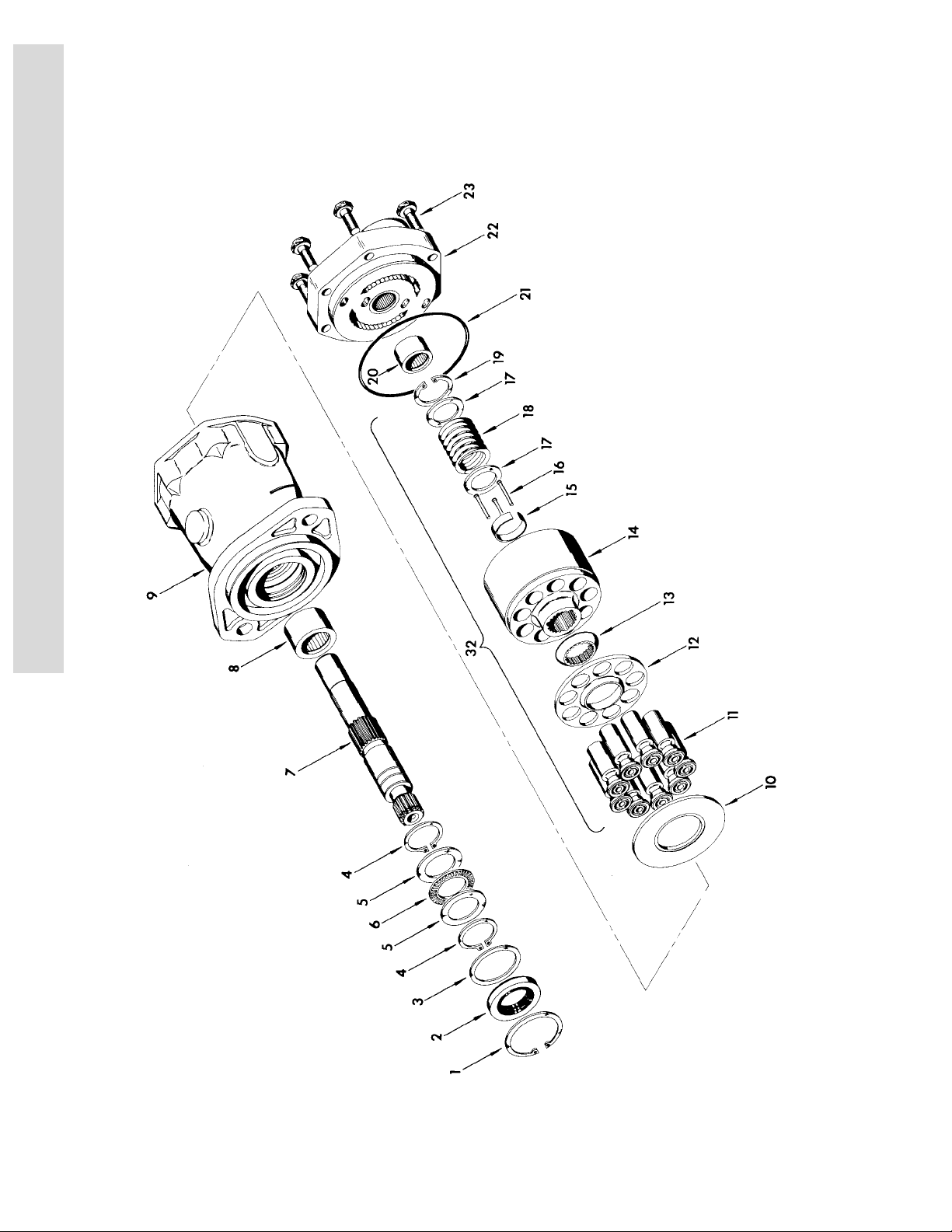
FIGURE 1-4. DRIVE MOTOR ASSEMBLY.
1-12 3120853

SECTION 1 FRAME
FIGURE 1-4. DRIVE MOTOR ASSEMBLY.
FIG & ITEM # PART NUMBER DESCRIPTION QTY. REV.
3160158 DRIVE MOTOR ASSEMBLY Ref. A
1 Kit Ring, Retaining 1
2 Kit Seal, Shaft 1
3 7004906 Washer 1
4 Kit Ring, Retaining 2
5 7004907 Race, Thrust 2
6 7004908 Bearing 1
7 7004974 Shaft, Drive 1
8 7004910 Bearing 1
9 7007875 Housing Assembly (Includes Item 8) 1
10 7007876 Camplate 1
11 7007880 Rotating Kit Assembly 1
12 7004917 Bearing 1
13 Kit O-Ring 1
14 7007878 Backplate Assembly (Includes Item 12) 1
15 7007879 Bolt 6
– – – – – – – – – –
2900714 Repair Kit Includes Items 1,2,4 and 13) 1
S
E
C
T
I
O
N
1
F
R
A
M
E
3120853 1-13

S
SECTION 1 FRAME
E
C
T
I
O
N
1
F
R
A
M
E
FIGURE 1-5. DRIVE BRAKE ASSEMBLY.
1-14 3120853

SECTION 1 FRAME
S
FIGURE 1-5. DRIVE BRAKE ASSEMBLY.
FIG & ITEM # PART NUMBER DESCRIPTION QTY. REV.
1 Kit Seal, Oil 1
2 Kit Bearing 1
3 7007977 Ring, Retaining 1
4Not Used
5Not Used
6Not Used
7Not Used
8Not Used
9Not Used
10 Not Used
11 Kit Seal, Case 1
12 Not Used
13 7007986 Cover 1
14 Not Used
15 7011716 Ring, Retainer 1
16 Not Used
17 7007987 Pin, Dowel 2
18 Kit Ring, Back-up 1
19 Kit O-Ring 1
20 Kit Ring, Back-up 1
21 Kit O-Ring 1
22 Kit Rotor 2
23 Kit Stator 2
24 Not Used
25 Not Used
26 Not Used
27 Not Used
28 Kit O-Ring 2
29 7007933 Gasket 2
– – – – – – – – – –
2900766 Seal Kit (Includes Items 1,11,18,19,20,21,28 and 29) 1
2900768 Bearing Kit (Includes Items 1,2,11,28 and 29) 1
E
C
T
I
O
N
1
F
R
A
M
E
0920084
0920110
51 Shaft Options: 1
7011712 Prior to S/N 33476
7011720 S/N 33476 to Present
52 Spring (Inner) Options: 6
7007979 Prior to S/N 33476
7007970 S/N 33476 to Present
53 Spring (Outer) Options: 6
7007980 Prior to S/N 33476
7018602 S/N 33476 to Present
54 Housing Options: 1
7011713 Prior to S/N 33476
7018605 S/N 33476 to Present
55 Bolt, Washer Head Options: 4
7007985 Prior to S/N 33476
7018607 S/N 33476 to Present
56 Guide, Spring Options: 1
7011717 Prior to S/N 33476
7018606 S/N 33476 to Present
57 Piston Options: 1
7007923 Prior to S/N 33476
7018603 S/N 33476 to Present
DRIVE BRAKE ASSEMBLY - MICO PRIOR TO S/N 33476
S/N 33476 TO PRESENT
Ref. –
Ref. A
3120853 1-15

S
E
C
T
I
O
N
1
F
R
A
M
E
SECTION 1 FRAME
FIGURE 1-5. DRIVE BRAKE ASSEMBLY. (CONTINUED)
FIG & ITEM # PART NUMBER DESCRIPTION QTY. REV.
58 Plate, Return 1
Kit
7011715 Separator Assembly 2
7011714 Pin 4
7007983 Separator 2
59 7018609 Plug 1
7018608 Lining Kit (Includes Items 58,11,22,23,28 and 29) 1
1-16 3120853

SECTION 1 FRAME
S
FIGURE 1-5. DRIVE BRAKE ASSEMBLY. (CONTINUED)
FIG & ITEM # PART NUMBER DESCRIPTION QTY. REV.
E
C
T
I
O
N
1
F
R
A
M
E
3120853 1-17

S
SECTION 1 FRAME
E
C
T
I
O
N
1
F
R
A
M
E
FIGURE 1-6. VALVES, BATTERY AND TILT INDICATOR INSTALLATIONS (FRAME
MOUNTED).
1-18 3120853

SECTION 1 FRAME
S
FIGURE 1-6. VALVES, BATTERY AND TILT INDICATOR INSTALLATIONS (FRAME MOUNTED).
FIG & ITEM # PART NUMBER DESCRIPTION QTY. REV.
0255994 VALVES INSTALLATION Ref. A
1 to 10 Not Used
11 0100011 Loctite #242 (Not Shown) A/R
12 4640969 Accessory Valve Assembly (See Figure 1-7 for 1
Breakdown)
13 0641506 Bolt 5/16"-18NC x 3/4" 3
14 4751500 Flatwasher 5/16" 7
15 3600208 Auxiliary Pump Assembly 1
15A 7013710 Motor, Replacement 1
7013753 Brush Kit - 7013710 Motor 1
15B 7013711 Coupling 1
15C 7013712 Pump, Replacement 1
16 0641606 Bolt 3/8’-16NC x 3/4" 2
17 4751600 Flatwasher 3/8" 2
18 3539716 Plate, Valve Mounting 1
19 0641508 Bolt 5/16"-18NC x 1" 2
20 3311505 Locknut 5/16"-18NC 4
21 4640976 Flow Divider Valve Assembly 1
21A 7017404 Cartridge, Flow Divider Valve 1
7017405 Seal Kit - 7017404 Valve 1
21B 7017406 Plug, Check 1
7012993 Orifice 1
22 0641526 Bolt 5/16"-18NC x 3 1/4" 2
23 4566987 Spacer 2
24 2120146 Filter Assembly 1
24A 2120150 Element, Filter 1
24B 7016312 Switch 1
25 0641405 Bolt 1/4"-20NC x 5/8" 4
26 4711400 Flatwasher 1/4" Narrow 6
27 4640974 Brake Release Valve Assembly 1
Not Available Seal Kit - 4640974 Valve 1
28 4640005 Valve, Needle 1
29 2900062 Valve Mounting Kit 1
30 4712200 Flatwasher 3/4" Narrow 1
31 0641414 Bolt 1/4"-20NC x 1 3/4" 2
32 3311405 Locknut 1/4"-20NC 2
33 4060807 Flex-Trim
34 1703030 Decal - Close (Tow Valve) 1
30in/76cm
E
C
T
I
O
N
1
F
R
A
M
E
0256405 TILT INDICATOR INSTALLATION Ref. B
101 4360442 Switch, Tilt Indicator 1
102 0641406 Bolt 1/4"-20NC x 3/4" 2
103 3311405 Locknut 1/4"-20NC 2
3120853 1-19

S
E
C
T
I
O
N
1
F
R
A
M
E
SECTION 1 FRAME
FIGURE 1-6. VALVES, BATTERY AND TILT INDICATOR INSTALLATIONS (FRAME MOUNTED).
FIG & ITEM # PART NUMBER DESCRIPTION QTY. REV.
0256307 BATTERY AND CABLES INSTALLATION Ref. C
201 0400003 Battery 1
202 0400002 Hold-down, Battery 1
202 A 2910479 Hold-down, Clips (Not Shown) 4
203 3980003 Seat, Battery 1
204 0630505 Bolt, Tie-down 2
205 3300371 Wingnut 1/4"-20NC 2
206 1060623 Cable, Battery (Positive) 1
207 1060624 Cable, Battery (Negative) 1
208 1060620 Cable, Battery (Auxiliary Pump) 1
209 3300401 Nut, Brass 1
210 0641508 Bolt 5/16"-18NC x 1" 1
211 4791500 Starwasher 5/16" 2
212 3311505 Locknut 5/16"-18NC 1
213 4751400 Flatwasher 1/4" 4
214 4761400 Lockwasher 1/4" 2
215 3311401 Nut 1/4"-20NC 2
216 3740067 Relay, Continuous Duty 1
217 2540021 Grommet 2
218 3300220 Nut, Special 1
219 3321001 Nut #10-32NF 1
220 4761000 Lockwasher #10 1
1-20 3120853

SECTION 1 FRAME
S
FIGURE 1-6. VALVES, BATTERY AND TILT INDICATOR INSTALLATIONS (FRAME MOUNTED).
FIG & ITEM # PART NUMBER DESCRIPTION QTY. REV.
E
C
T
I
O
N
1
F
R
A
M
E
3120853 1-21

S
SECTION 1 FRAME
E
C
T
I
O
N
1
F
R
A
M
E
FIGURE 1-7. ACCESSORY VALVE ASSEMBLY.
1-22 3120853

SECTION 1 FRAME
FIGURE 1-7. ACCESSORY VALVE ASSEMBLY.
FIG & ITEM # PART NUMBER DESCRIPTION QTY. REV.
4640969 ACCESSORY VALVE ASSEMBLY Ref. E
1 Not Serviced Block, Manifold 1
2 7017410 Cartridge, Solenoid Valve (Less Coil) 1
7012967 Seal Kit - 7017410 Valve 1
2A 7012944 Coil, Solenoid 1
3 7012969 Cartridge, Check Valve 1
7012540 Seal Kit - 7012969 Valve 1
4 7017419 Cartridge, Relief Valve 1
7012953 Seal Kit - 7017419 Valve 1
5 7012968 Cartridge, Pilot Valve 1
7012518 Seal Kit - 7012968 Valve 1
6 7010542 Cartridge, Shuttle Valve 2
7010543 Seal Kit - 7010543 Valve 2
7 7018902 Plug, Orifice - 1.5mm 2
8 7017429 Cartridge, Relief Valve 2
7012967 Seal Kit - 7017429 Valve 2
9 7012941 Cartridge, Solenoid Valve (Less Coil) 1
7012907 Seal Kit - 7012941 Valve 1
9A 7012944 Coil, Solenoid 1
10 7012795 Control Valve Assembly 1
7012773 Seal Kit - 7012795 Valve 1
10A 7012772 Coil, Solenoid 2
10B 7018912 Nut, Coil 2
11 7018913 Control Valve Assembly 1
7012773 Seal Kit - 7018913 Valve 1
11A 7012772 Coil, Solenoid 1
11B 7018912 Nut, Coil 1
11C 7018916 Plug, Orifice - 2mm 1
12 7018905 Plug 1
S
E
C
T
I
O
N
1
F
R
A
M
E
3120853 1-23
S
SECTION 1 FRAME
E
C
T
I
O
N
1
F
R
A
M
E
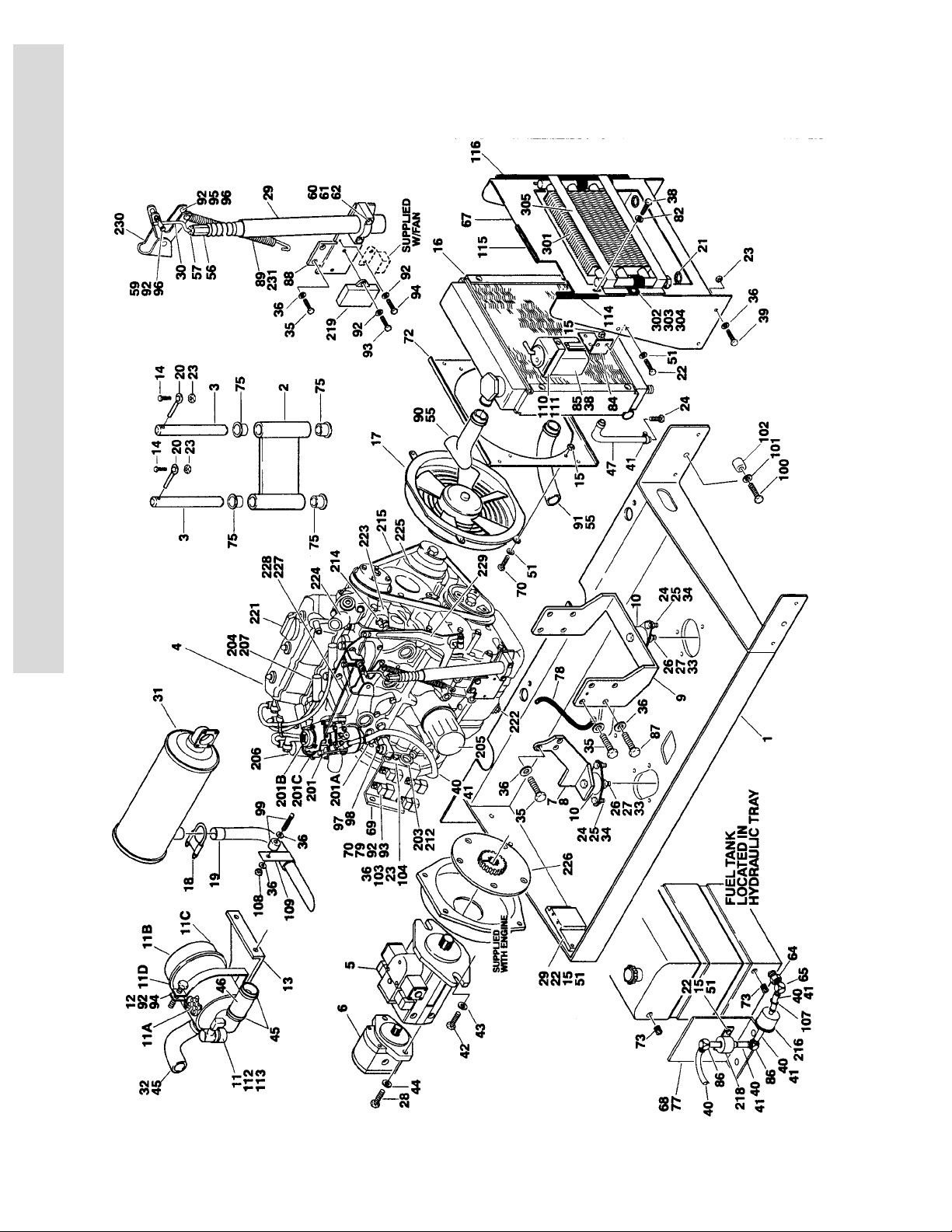
FIGURE 1-8. VANGUARD GAS ENGINE INSTALLATIONS.
1-24 3120853
 Loading...