

Operation, Safety, Maintenance
and service Manual
Original Instructions - Keep this manual with the machine at all times.
Boom Lift Models
X20JPLUS
X20JPR002
April, 2013


JLG LIFT
FOREWORD
For:
• Accident Reporting
• Product Safety Publications
• Current Owner Updates
• Questions Regarding Product Safety
• Standards and Regulations Compliance Information
• Questions Regarding Special Product Applications
• Questions Regarding Product Modifications
Contact:
Product Safety and Reliability Department
JLG Industries, Inc.
13224 Fountainhead Plaza
Hagerstown, MD 21742
or Your Local JLG Office
(See addresses on manual cover)
In USA:
Toll Free: 877‑JLG‑SAFE (877‑554‑7233)
Outside USA:
Phone: 240‑420‑2661
Fax: 301‑745‑3713
E‑mail: ProductSafety@JLG.com
X20JPR002

X20JPR002
REVISION LOG
Rev. Manual code Date
Original Issue X20JPR002 April, 2013
JLG LIFT
FOREWORD

BOOM LIFT MODELS X20JPLUS
JLG
TABLE OF CONTENTS
CHAPTER 1 PRESENTATION ....................................................................................Page 08
CHAPTER 2 TECHNICAL INFORMATION ...........................................................Page 09
2.1 Description of the machine ...................................................................Page 09
2.1.1 Control position .....................................................................................Page 09
2.1.2 Machine identification plate .................................................................Page 12
2.1.3 Overall dimensions of the machine .....................................................Page 13
2.1.4 Technical specifications .........................................................................Page 14
2.1.4.1 Petrol engine technical specifications ..................................................Page 15
2.1.4.2 Diesel engine technical specifications..................................................Page 15
2.1.4.3 Hydraulic system technical specifications ..........................................Page 15
2.1.4.4 Electrical system technical specifications Thermic ............................Page 16
2.1.4.5 Electrical system technical specifications Lithium ............................Page 16
2.1.5 Terminology ............................................................................................Page 17
2.2 General safety standards .......................................................................Page 18
2.3 Safety warnings.......................................................................................Page 22
2.3.1 Generalities..............................................................................................Page 22
2.3.2 Noise and vibrations ..............................................................................Page 22
2.3.3 Pictograms positioned on the machine ...............................................Page 23
CHAPTER 3 SAFETY DEVICES..................................................................................Page 38
3.1 Battery cutout switch .............................................................................Page 39
3.2 Distributor pressure relief valves.........................................................Page 39
3.3 Cylinder stop valves...............................................................................Page 40
3.4 Alignment photocell on the aerial part of the structure and the
base of the machine ...............................................................................Page 40
3.5 Stabiliser position microswitches.........................................................Page 41
3.6 Jib position microswitch ........................................................................Page 41
3.7 Basket load sensor ..................................................................................Page 42
3.8 Control protection ..................................................................................Page 43
3.9 Spirit level ................................................................................................Page 43
3.10 Pin locking bolts and nuts .....................................................................Page 44
3.11 Safety device electronic control board.................................................Page 44
CHAPTER 4 INSTRUMENTS AND CONTROLS.....................................................Page 46
4.1 Remote control ........................................................................................Page 46
4.1.1 Display .....................................................................................................Page 47
4.1.1.1 Display main screen ...............................................................................Page 47
4.1.2 Joysticks ...................................................................................................Page 51
4.1.3 Push buttons............................................................................................Page 53
4.2 Footswitch ...............................................................................................Page 57
4.3 Control positions ...................................................................................Page 57
CHAPTER 5 EMERGENCY DEVICES .......................................................................Page 58
5.1 Emergency stop button..........................................................................Page 58
5.2 Hand pump .............................................................................................Page 59
5.3 Solenoid valves for emergency descent...............................................Page 59
5.4 Safety device bypass key .......................................................................Page 60
5.5 Emergency position controls.................................................................Page 61
CHAPTER 6 USING THE MACHINE........................................................................Page 66
6.1 Safety standards to adopt before using the platform ................................Page 66
6.1.1 Risk of electrocution...............................................................................Page 66
6.1.2 Danger due to atmospheric conditions ..............................................Page 67
6.1.3 Danger due to the work area ................................................................Page 67
6.2 Procedures for correct use.....................................................................Page 68
6.2.1 Summary table of operator safety standards......................................Page 68
6.3 Working area...........................................................................................Page 70
6.4 Using the elevating work platform (MEWP) .....................................Page 71
1
X20JPR0020413

6.4.1 Preliminary checks before starting work ...........................................Page 72
6.4.2 Starting the petrol/diesel engine .........................................................Page 73
6.4.3 Starting the electric motor ...................................................................Page 74
6.4.4 Stopping the engine/motor ...................................................................Page 76
6.4.5 Stopping the motor lithium version ....................................................Page 76
6.4.6 Travel ........................................................................................................Page 77
6.4.7 Jib arm movement for travel.................................................................Page 80
6.4.8 Parking the machine on a slope or on uneven ground ....................Page 82
6.4.9 Stabilising and levelling the machine..................................................Page 82
6.4.10 Automatic lowering and raising of the stabilisers ............................Page 86
6.4.11 Track gauge extension............................................................................Page 88
6.4.12 Moving the basket .................................................................................Page 89
6.4.13 Manually levelling the basket ..............................................................Page 93
6.5 Emergency operations on the aerial part ...........................................Page 94
6.5.1 Emergency descent controlled from the basket .................................Page 94
6.5.2 Operating the machine from the emergency control position
on the ground if the operator is taken ill ............................................Page 95
6.5.3 Emergency descent in the case where the stabilisers are
accidentally retracted .............................................................................Page 96
6.5.4 Emergency descent controlled from the ground using the hand
pump in the event of faults on all energy supply systems .............Page 98
6.5.5 Emergency operations on the carriage: moving the platform
stabilisers using the hand pump to allow the machine
to be transported.....................................................................................Page 100
6.5.6 Emergency operation of the undercarriage in the event of
movements of the aerial part ................................................................Page 101
6.6 Electrical disconnection of the remote control ...................................Page 103
6.7 Recharging the battery ..........................................................................Page 104
6.8 Main intended uses of the platform.....................................................Page 108
6.8.1 Systems.....................................................................................................Page 108
6.8.2 Closed environments .............................................................................Page 108
6.8.3 Pruning.....................................................................................................Page 108
6.8.4 Repair and maintenance of roofing and gutters ................................Page 109
6.8.5 Painting, sand‑blasting and plastering................................................Page 109
6.8.6 Use in marine environments.................................................................Page 109
CHAPTER 7 MAINTENANCE....................................................................................Page 110
7.1 Safety instructions for greasing and lubrication ................................Page 110
7.2 Table of recommended lubricants ........................................................Page 110
7.3 Greasing points .......................................................................................Page 112
7.4 Greasing the telescopic arm ..................................................................Page 113
7.5 Safety instructions for maintenance operations.................................Page 113
7.6 Operating the machine from the second control position on the
ground using the optional second remote control during
maintenance ............................................................................................Page 114
7.7 Periodic maintenance intervals.............................................................Page 115
7.8 Electric motor ..........................................................................................Page 117
7.8.1 Electric motor maintenance ..................................................................Page 117
7.9 Inspection and maintenance .................................................................Page 118
7.10 General periodic checks.........................................................................Page 120
7.11 Maintenance on the rubber tracks .......................................................Page 121
7.11.1 Checking the track tension....................................................................Page 121
7.11.2 Loosening/tightening the tracks...........................................................Page 121
7.11.3 Checking the rubber tracks ...................................................................Page 122
7.11.4 Replacing the rubber tracks ..................................................................Page 124
7.12 Checking tightness of nuts and bolts...................................................Page 125
7.13 Checking the hydraulic oil level...........................................................Page 129
7.13.1 Hydraulic oil............................................................................................Page 129
7.14 Checking for leaks in the hydraulic system........................................Page 129
7.15 Checking the condition of the filter cartridge ....................................Page 130
2
X20JPR0020413
BOOM LIFT MODELS X20JPLUS
JLG

3
7.16 Checking that all the plates are present on the machine
and intact .................................................................................................Page 130
7.17 Checking the operating pressure of the hydraulic system...............Page 131
7.18 Checking tightness of the fastening screws on the pin retainers
and the locknuts......................................................................................Page 131
7.19 Replacing /checking extension ropes...................................................Page 132
7.19.1 Checking wear and deformation of ropes and pulleys.....................Page 132
7.20 Three‑monthly inspection .....................................................................Page 133
7.21 Five‑yearly inspection............................................................................Page 135
7.22 Checking wear on the telescopic arm slides.......................................Page 136
7.23 Checking extension pulley wear ..........................................................Page 136
7.24 Checking tightness of the turntable bolts............................................Page 136
7.25 Battery: checks and maintenance ‑ thermic version ..........................Page 136
7.25.1 Checking the electrolyte level ‑ thermic version................................Page 137
7.25.2 Recharging the battery ‑ thermic version............................................Page 137
7.25.3 Replacing the battery ‑ thermic version ..............................................Page 138
7.25.4 Battery disposal.......................................................................................Page 138
7.26 Battery pack operating specifications..................................................Page 139
7.26.1 Components and diagrams ...................................................................Page 140
7.26.2 Personal protective equipment.............................................................Page 142
7.26.3 Handling in dangerous conditions ......................................................Page 142
7.26.3.1 Procedure for handling hot cells ..........................................................Page 143
7.26.3.2 Procedure for handling vented cells....................................................Page 144
7.26.3.3 Procedure for exploded cells.................................................................Page 145
7.26.3.4 Lithium battery fire ................................................................................Page 147
7.27 Servicing the engine ...............................................................................Page 149
CHAPTER 8 SAFETY STANDARDS FOR TRANSPORT ........................................Page 150
8.1 Removing the basket..............................................................................Page 150
8.2 Loading and unloading the machine on transport vehicles
using ramps .............................................................................................Page 151
8.3 Lifting the machine.................................................................................Page 152
8.3.1 Lifting the machine using a forklift ....................................................Page 153
8.3.2 Lifting the machine using ropes or chains ........................................Page 154
8.3.3 What to use to attach the platform.......................................................Page 155
8.4 Transporting the machine......................................................................Page 156
CHAPTER 9 SERVICE MENU ON THE REMOTE CONTROL .............................Page 157
9.1 Input menu ..............................................................................................Page 157
9.2 Error menu...............................................................................................Page 159
9.3 Operating hours menu...........................................................................Page 159
9.4 Settings menu..........................................................................................Page 159
9.5 Joystick menu ..........................................................................................Page 159
CHAPTER 10 TROUBLESHOOTING...........................................................................Page 160
CHAPTER 11 CHECKS TO BE COMPLETED ON THE MACHINE
FOLLOWING REPAIRS.........................................................................Page 168
11.1 Checking correct operation of the controls.........................................Page 168
11.2 Checking operation of the safety devices............................................Page 168
CHAPTER 12 HYDRAULIC SYSTEM..........................................................................Page 169
12.1 Hydraulic system diagram thermic version.......................................Page 169
12.1.1 Key to the hydraulic system diagram thermic version.....................Page 170
CHAPTER 13 WIRING DIAGRAM ..............................................................................Page 171
BOOM LIFT MODELS X20JPLUS
JLG
X20JPR0020413
PREFACE
The aim of this manual is to provide the user with the necessary instructions and essential
operating procedures to ensure correct and safe use of the machine for its intended purpo‑
ses, as well as to prevent serious injury to the operator and other persons.
IMPORTANT
IT IS MANDATORY TO KEEP TO ALL THE INSTRUCTIONS GIVEN IN THIS MANUAL.
THIS MANUAL MUST BE CAREFULLY READ AND UNDERSTOOD BEFORE OPERA‑
TING THE MACHINE.
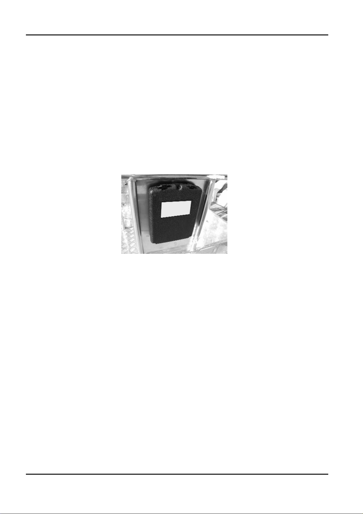
As this manual is an essential work tool, it must be kept with the machine at all times, in the
special compartment, so as to be available for clarification whenever required.
As the manufacturer cannot control the conditions of the machine and the operations this is
used for, THE USER IS RESPONSIBLE for ensuring compliance with the safety procedures
described in this manual.
Every machine supplied is thoroughly adjusted and tested before being delivered. The ope‑
rator does not need to perform any adjustments before using the machine.
Every alteration and/or modification of the features of the original machine design without
previous written authorisation from the Constructor are PROHIBITED and THE RESPONSI‑
BILITY FOR THESE ACTIONS FALLS ON THE OPERATOR.
THE EMPLOYER MUST MAKE SURE THAT THE OPERATOR HAS THE REQUISITES
NECESSARY TO OPERATE THE MACHINE CORRECTLY AND THAT SUCH OPERA‑
TOR HAS CAREFULLY EXAMINED AND UNDERSTOOD THE INFORMATION
GIVEN IN THIS USER AND OPERATION MANUAL, RECEIVING SUITABLE TRAI‑
NING REGARDING USE OF THE MACHINE IN STANDARD AND EMERGENCY
CONDITIONS.
THE EMPLOYER MUST ALSO TRAIN OPERATORS REGARDING ANY NATIONAL
STANDARDS THAT ARE IN ADDITION TO THE INSTRUCTIONS CONTAINED IN
THIS DOCUMENT.
If the manual is damaged or lost, a copy must be requested directly from JLG.
X20JPR0020413
4
BOOM LIFT MODELS X20JPLUS
JLG

Note: All of the photos and drawings in this manual have been added to simplify com‑
prehension by the reader. Your machine may differ from the photos and drawings provi‑
ded.
NORMATIVE REFERENCES
The machine has been designed, built and inspected according to that prescribed in the
EN280 prA2:2009 harmonised standard, which supplies the presumption of conformity with
the Essential Safety Requisites of the 2006/42/CE Machinery Directive even if a type C Volun‑
tary Technical Standard.
According to that stated in EN280 prA2, the JLG platform is classified in GROUP B, as the
vertical projection of the centre of gravity of the load can be outside of the tilting lines and in
TYPE 1 as traversing is only allowed with the platform at rest.
The stability tests of the machine have been made in accordance with what described in
paragraph 6.1.4.2 of the EN280 with load test calculated in conformity with 5.2.4 and have
been successful.
In addition what prescribed in this manual it is necessary to apply the technical require‑
ments of the following national/international safety standards:
‑ UNI ISO 18893
‑ ISO 16368
‑ ISO 18878
With the exception of stricter local or national regulations in the working area of the MEWP.
WARRANTY
On purchasing a JLG platform, a warranty and inspection certificate is issued that clearly
indicates the warranty terms and where any interventions on the machine must be reported.
LIABILITY
The Constructor is exonerated from any liability and obligation for any injury/damage cau‑
sed to persons/objects due to any of the reasons listed below:
• Failure to comply with the instructions indicated in this USE AND MAINTENANCE
MANUAL regarding running, use and maintenance of the machine;
• Violent or sudden actions or incorrect manoeuvres when using or servicing the machine;
• Modifications made to the structure or machine components without previous authori‑
sation from the Constructor and/or without the use of suitable equipment;
• Strange events with respect to normal and correct use of the machine, described in this
USE AND MAINTENANCE MANUAL.
• Use of non‑original spare parts not authorised by the manufacturer.
X20JPR0020413
BOOM LIFT MODELS X20JPLUS
JLG
5
X20JPR0020413
6
BOOM LIFT MODELS X20JPLUS
JLG
EC DECLARATION OF CONFORMITY
EC DECLARATION OF
CONFORMITY
Manufacturer
Address
Technical File:
Authorised contact
Machine Type:
Model Type:
Serial Number:
Notified Body:
EC Number:
Address
JLG Industries Inc
1 JLG Drive
McConnellsburg
PA17233
USA
JLG Industries Inc
JLG Technology & Development Centre
Bruntingthorpe Aerodrome & Proving Ground
Lutterworth, Leicestershire
LE17 5QS
United Kingdom.
Alan S. McInt
Mobile Elevating Work Platform
...
...
ECO Certificazioni S.p.A
0714
Via Mengollna
33 - 48108
Faenza
Italy
yre
Position:
Manager, Engineering
Support - Europe
Certificate Number:
Reference Standards:
JLG Industries hereby declare that the above mentioned machine conforms
with the requirements of:
2006/42/EC Machiner
2004/108/EC EMC Directive
2000/14/EC Outdoor Noise
Signed:
Name: Alan S. McIntyre Position: Manager,Engineering Support-
Remark:
An
y modification to the above described machine violates the validity of this declaration.
This declaration conforms with the requirements of annex II-A of the council directive
2006/42/EC
Machine manufactured for JLG Industries Inc. by HINOWA S.p.a via Fontana 37054
NOGARA VR Ital
y
To Be Advised
EN12100-1 & 2:2003 + A1:2009
EN280:2001 + A2:2009
y
Date: ...
Europe
Place: Bruntingthorpe, UK

7
BOOM LIFT MODELS X20JPLUS
JLG
X20JPR0020413
y
y
EC DECLARATION OF
CONFORMITY
Manufacturer
Address
Machine Type:
Model Type:
Serial Number:
Document Control:
Measured
Lwa
Guaranteed
Lwa ...dB(A)
Engine Power:
...kW
Lwa = (Sound Power Level)
JLG Industries Inc
1 JLG Drive
McConnellsburg
PA17233
USA
Mobile Elevating Work Platform
...
...
HINOWA S.p.A
Via Fontana - 37054
Nogara
Italy
...dB(A)
Technical File:
JLG Industries Inc
JLG Technology &
Development Centre
Bruntingthorpe
Aerodrome & Proving
Ground
Lutterworth,
Leicestershire
LE17 5QS
United Kingdom.
Applicable Procedure:
Applicable Directive:
EN ISO 3744:1995
2000/14/EC Annex V Internal Control of Production.
We hereby declare that the above mentioned machine
conforms with the requirements of the "Noise Emission in
the Environment by Equipment for Use Outdoors"
Directive 2000/14/EC & 2005/88/EC
Remark:
This declaration conforms with the requirements of Annex II of the council directive
2000/14/EC
An
modification to the above described machine violates the validity of this declaration.
Machine manufactured for JLG Industries Inc. by HINOWA S.p.a via Fontana 37054
NOGARA VR Ital
1. PRESENTATION
This manual describes the warning signs used to draw the reader’s attention to several parti‑
cularly important warnings.
The safety warnings are divided into two main types, which are identified and described
below.
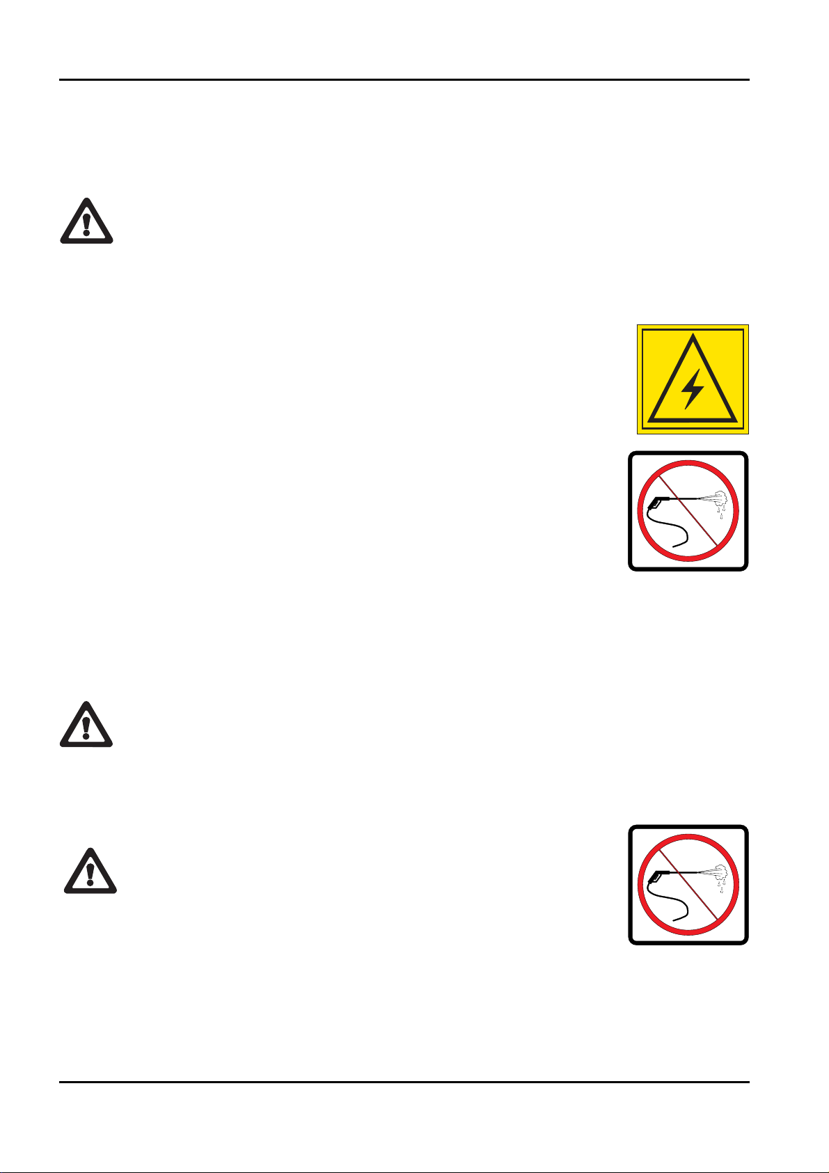
DANGER
This symbol accompanied by the word DANGER indicates that the situation
described, if not prevented, can lead to serious injury or death of the persons
involved (operator, ground staff, staff present in proximity to the platform, main‑
tenance technicians etc.).
WARNING
This symbol accompanied by the word WARNING indicates that the situation
described represents a potential risk for the structure of the machine.
Dangerous situations may be determined by this condition (including injury or
death) for the persons involved.
BOOM LIFT MODELS X20JPLUS
JLG
8
X20JPR0020413
2. TECHNICAL INFORMATION
2.1. DESCRIPTION OF THE MACHINE
The JLG machine is a self‑propelled hydraulic lifting device, equipped with a rotating work
basket positioned at the top of an extendable articulated structure, which also rotates. The
JLG lifting device is destined for the POSITIONING OF PERSONS AND THEIR EQUIP‑
MENT AND MATERIALS IN HIGH POSITIONS WITH RESPECT TO GROUND LEVEL.
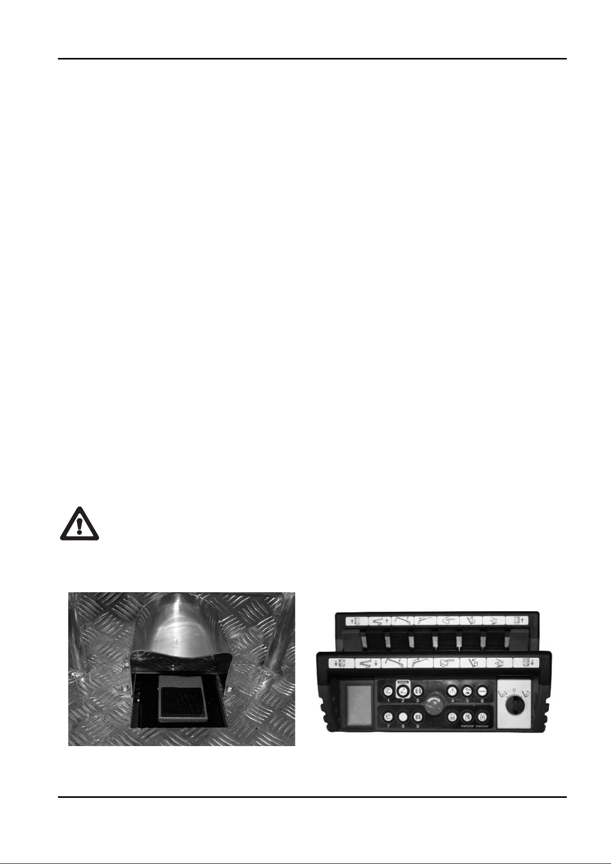
2.1.1 CONTROL POSITION
‑ CONTROL POSITION IN THE BASKET
The JLG aerial work platform has been designed to be controlled by the operator in the
basket using a remote control, where all of the machine functional controls are gathered,
positioned in the relevant support inside the basket (see photo). A pedal (optional) is also
present in the basket in order to allow the movement of the aerial part (see picture).
From this control position it is possible to control the extendible structure and machine stabi‑
lisation. When the machine is manoeuvred from the control position in the basket, the remo‑
te control must be positioned in the appropriate seat, and the footswitch must be activated
(the footswitch must be release and activated again if no movements are made for more than
7 second). The remote control is connected to the machine using a flexible cable that allows
to shift it if the basket is to be removed or the ground control unit is to be used.
Stabilisation of the machine must be preferably controlled from the basket drive position.
Machine traversing must be carried out from the control position on the ground.
After accessing or leaving the control position in the basket, ALWAYS remember to close
the ladder, to avoid any damage when operating the machine.
X20JPR0020413
BOOM LIFT MODELS X20JPLUS
JLG
9
DANGER
ATTENZIONE
CONTROL POSITION ON THE GROUND:
There is a second control position available for the tracked part of the machine. This is not in
a fixed position but rather can be located on the ground within a radius of 2.5 m from the
basket attachment. To control the machine from this position, the operator uses the same
remote control, removing it from its housing in the basket and using the cable provided.
From this control position, the operator IS NOT enabled to control the aerial
part of the machine, but only the tracks, stabilisers and track extension func‑
tion.
DANGER! when controlling the machine from the ground position, keep a
distance of at least 1 m from the tracks.
DANGER! when controlling the machine from the ground position, always
make sure that the component that is being moved is completely visible and
constantly check its trajectory.
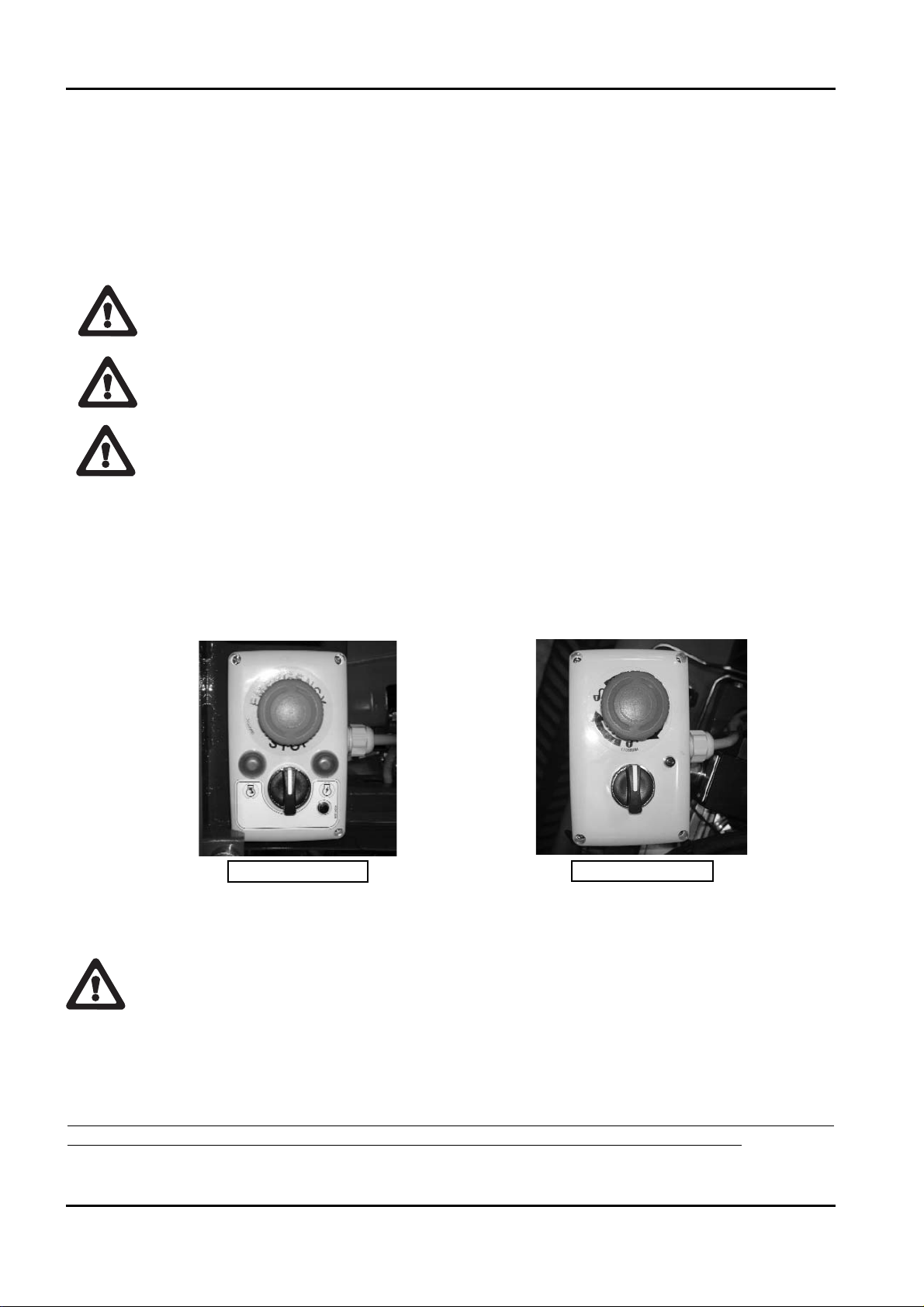
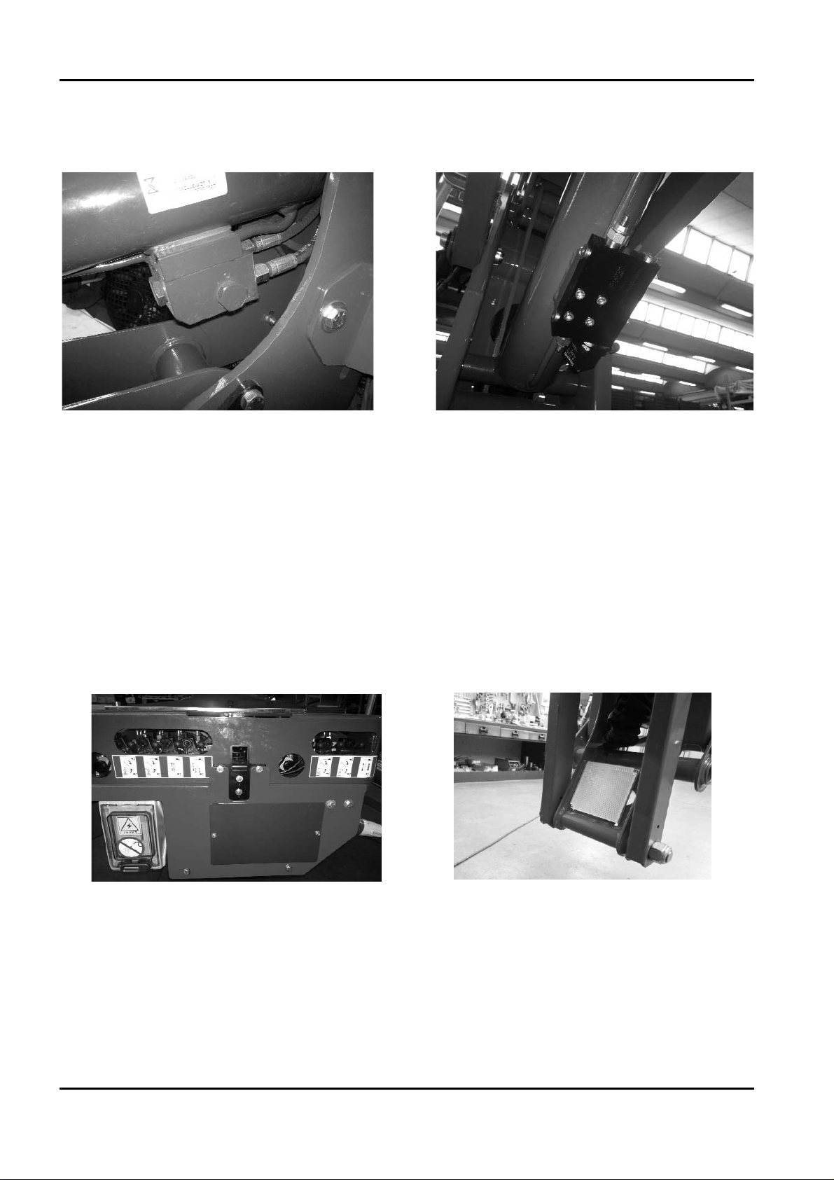
‑ EMERGENCY CONTROL POSITION
There is a control position which will be identified as the emergency control position. This is
located on the ground part of the machine, next to the distributor for the aerial part. To ena‑
ble it, press the special selector positioned on the base of the turret (see photo) until the green
warning light comes on. The light indicates that the movements of the aerial part are ena‑
bled.
From this position, the movements of the machine can be controlled directly using the levers
on the various hydraulic distributors, aerial part (see photo 1) and proportional (aerial part,
see photo 2).
The emergency control position was designed to operate on the extensible structure only
for emergency operations by emergency service personnel on the ground, who must in
any case be trained and know the operation of the machine and its safety devices, as well
as for maintenance and checks before starting work.
If an operator is in the basket, it is forbidden to move the structure from the ground posi‑
tion, unless in an emergency situation (sudden operator illness, technical fault).
X20JPR0020413
10
BOOM LIFT MODELS X20JPLUS
JLG
THERMIC MOTOR
LITHIUM MOTOR
DANGER
ATTENZIONE
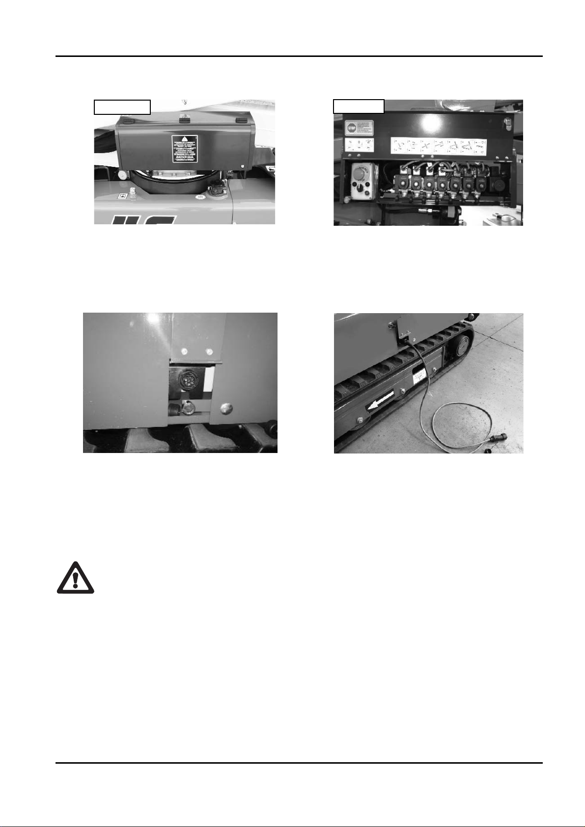
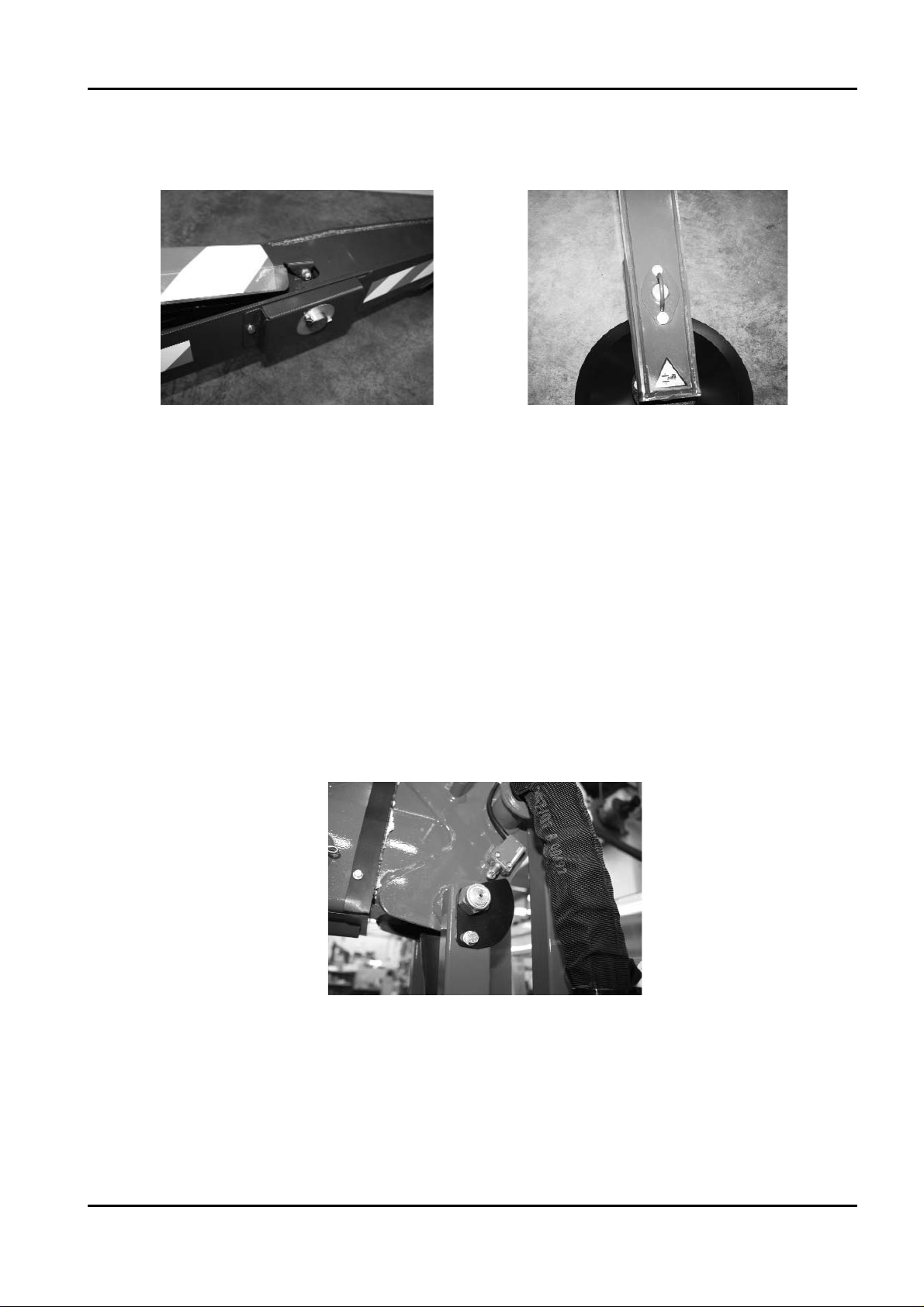
There is a control position available only for scheduled and unscheduled maintenance opera‑
tions, placed near the electrical components compartment on the machine.
On the electric board protection there is an auxiliary connector for the connection of the
optional second remote control (see photo).
To enable this position, use the key selector placed on the base of the turret and connect the
optional second remote control to the machine.
Before proceeding with the connection, carefully read the paragraph regarding the use of
the optional second remote control.
This control position can only be used to carry out checks and maintenance on the machine.
Do not use this position to control the machine during normal operations.
Note: it is absolutely forbidden to move the machine from this position if one ore more
operators are in the basket.
X20JPR0020413
BOOM LIFT MODELS X20JPLUS
JLG
11
FOTO 1
FOTO 2
OPTIONAL SECOND REMOTE
CONTROL CONNECTOR POSITION
OPTIONAL SECOND REMOTE
CONTROL CONNECTOR
DANGER
ATTENZIONE
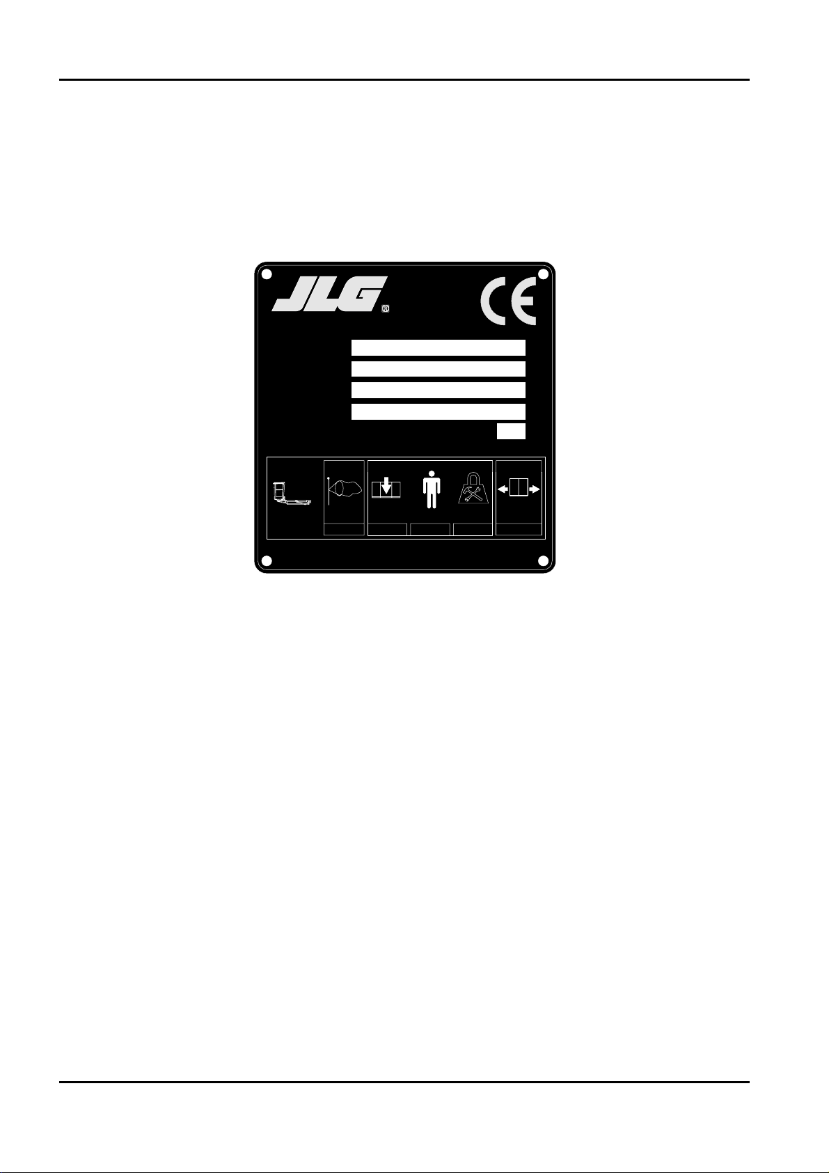
2.1.2 MACHINE IDENTIFICATION PLATE
The manufacturer plate is placed on the protection of the aerial part hydraulic distributor.
The drawing is shown below.
X20JPR0020413
12
BOOM LIFT MODELS X20JPLUS
JLG
xsm1;Manufactured by
HINOWA S.p.A.
Via Fontana
JLG Industries. Inc - McConnellsburg. PA - USA
Model
Serial number
Date of manufacture
G.V.W. (Dry)
MAXIMUM ALLOWABLE OPERATING INCLINATION
37054 NOGARA (VR)
ITALY
kg
1°
=+
MAX
12.5 230 70
kgM/S kg kg
2x80
400
07253100
N
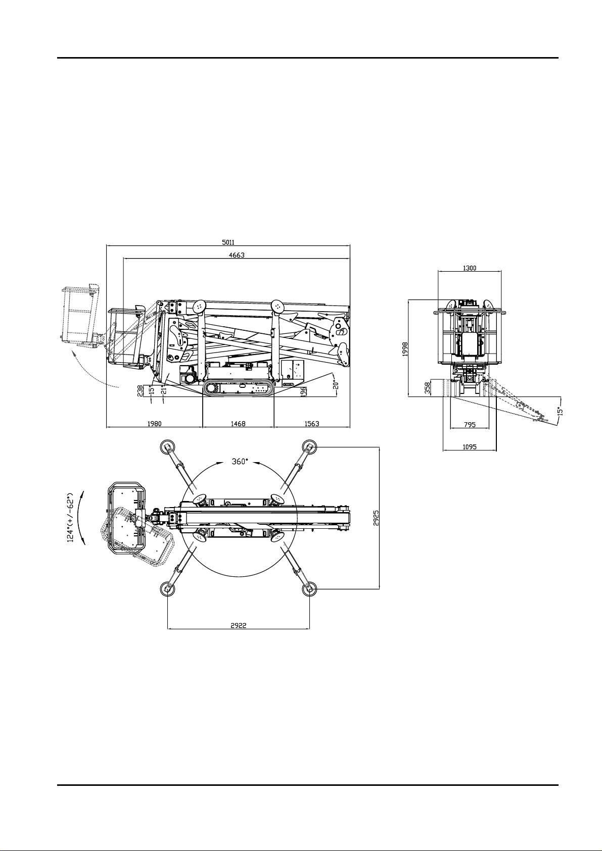
2.1.3 OVERALL DIMENSIONS OF THE MACHINE
Maximum length in travel configuration with basket installed ......................5011 mm
Track width ..............................................................................................................795/1095 mm
Maximum height in travel configuration with foot plates removed ..............1998 mm
Maximum attachment angle..................................................................................20°/ 36,4%
Maximum stabilisation angle ................................................................................15°
Max stabiliser base side (disc centre) ..................................................................2922x2925 mm
Nota: standard version with two‑operator basket.
X20JPR0020413
BOOM LIFT MODELS X20JPLUS
JLG
13

2.1.4 TECHNICAL SPECIFICATIONS
NB: Side extension is measured from the centre of the turntable to the outside edge of the
basket.
BOOM LIFT MODELS X20JPLUS
JLG
14
X20JPR0020413
PLATFORM CAPACITY 230 kg
PLATFORM HEIGHT (floor) 18,05 m
MAX WORKING HEIGHT 20,15 m
STANDARD BASKET DIMENSIONS 1335 x 690 x H1100 mm
MAX HORIZONTAL EXTENSION IN BASKET 9,20 m
MAX HORIZONTAL OUTREACH 9,70 m
ROTATION (non-continuous) 360°
BASKET ROTATION 124° (+/- 62°)
MAX GROUND REACTION FORCE FOR EACH
STABILISER
2150 daN
MAX GROUND PRESSURE FOR EACH STABILISER 3,04 daN/cm
2
NO. OF OPERATORS 2
NO. OF OPERATORS WITH OPTIONAL SINGLE-OPERATOR
BASKET
1
JIB - TYPE OF ARTICULATED JOINT 89°(+0°/-89°)
MAX WORKING GRADIENT 1°/1,75%
MAX STABILISATION SLOPE 15°
TOTAL WEIGHT IN TRANSPORT CONFIGURATION
(PETROL ENGINE)
2880 kg
ENGINE
HONDA iGX440 - (12,7 cv) / 3600 rpm
PERKINS 402.05 - (14 cv) / 3600 rpm
ELECTRIC MOTOR 2,2 kw / 230V / 50Hz 1500 rpm
ELECTRICAL SYSTEM VOLTAGE 12 V
PUMPS PETROL ENGINE double 2x4 cm³
PUMPS DIESEL ENGINE double 2x4 cm³
MAX TRANSLATION SPEED WITH STANDARD 2NDSPEED
(thermic motor)
0,5/1,3 / 2,5 Km/h
TRAVEL/STAB. SYSTEM PRESSURE 165 bar
AERIAL PART SYSTEM PRESSURE 210 bar
MAX SLOPE ALLOWED IN TRAVEL DIRECTION 15°
MAX WIND SPEED 12,5 m/s
MAX MANUAL FORCE ALLOWED 400 N

15
BOOM LIFT MODELS X20JPLUS
JLG
X20JPR0020413
2.1.4.1 TECHNICAL DATA – PETROL ENGINE
Make/Model ................................................................................HONDA iGX440
Fuel/Cooling ................................................................................PETROL/AIR
Power SAEJ1349 ..........................................................................9,5 Kw (12,7cv) / 3600rpm
Max speed ....................................................................................3600 rpm
Maximum torque ........................................................................29,8 Nm/2500 rpm (80/1269/EC)
Number of cylinders ............................................................................1
Displacement ..............................................................................440 cm
3
Sound power level at operator’s ear ........................................88 dB
Measured sound power level ..................................................102 dB
Granted sound power level ......................................................104 dB
2.1.4.2 TECHNICAL DATA – DIESEL ENGINE
Make/Model ................................................................................PERKINS 402.05
Fuel/Cooling ................................................................................DIESEL/AIR
Power SAEJ1349 ..........................................................................10,2 Kw (14cv) / 3600rpm
Max speed ....................................................................................3500 rpm
Maximum torque ........................................................................29,7 Nm/2400 rpm (80/1269/EC)
Number of cylinders ............................................................................2
Displacement ..............................................................................510 cm
3
Sound power level at operator’s ear ........................................90 dB
Measured sound power level ..................................................102 dB
Granted sound power level ......................................................104 dB
2.1.4.3 HYDRAULIC SYSTEM TECHNICAL SPECIFICATIONS
Hydraulic oil tank capacity ......................................................40 litres
Pump petrol engine ....................................................................double pump 2x4 cm
3
Pump diesel engine ....................................................................double pump 2x4 cm
3
Hydraulic system max pressure ..............................................210 bars
For further information, see the hydraulic diagram enclosed with the manual and the para‑
graph on maintenance of the hydraulic components.

2.1.4.4 ELECTRICAL SYSTEM TECHNICAL SPECIFICATIONS THERMIC
Battery ................................................................................55 Ah ‑ 240 A ‑ 12V
Alternator petrol engine ..................................................20 A (3600 rpm)
Alternator diesel engine ..................................................15 A (3600 rpm)
Electric motor: ‑ rated voltage ......................................230 V
‑ frequency............................................50 Hz
‑ rated power........................................2,2 kW
For further information, see wiring diagram enclosed with the manual and the paragraph on
maintenance of electrical components.
2.1.4.5 ELECTRICAL SYSTEM TECHNICAL SPECIFICATIONS LITHIUM
Battery ................................................................................90 Ah ‑ 70V
Electric motor: ‑ rated voltage ......................................48 V
‑ rated power........................................2 kW
Sound power level at operator’s ear ..............................70 dB
Measured sound power level ..........................................86 dB
Granted sound power level..............................................88 dB
Onboard battery charger ..................................................220V±30V 50÷60Hz
Battery charger (option)....................................................110V±30V 50÷60Hz
For further information, see wiring diagram enclosed with the manual and the paragraph on
maintenance of electrical components.
X20JPR0020413
16
BOOM LIFT MODELS X20JPLUS
JLG
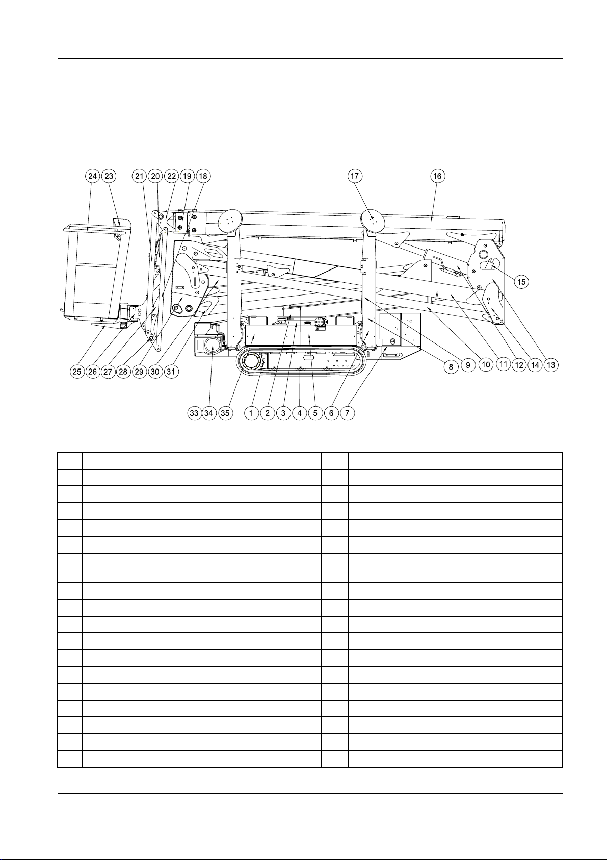
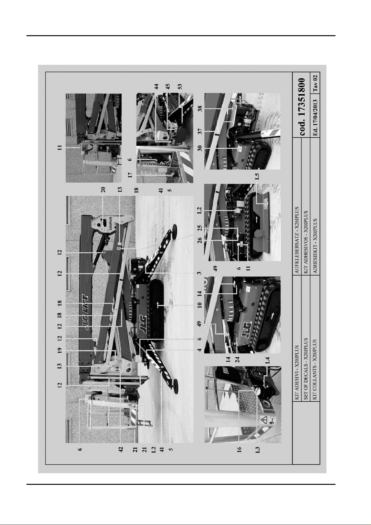
2.1.5 TERMINOLOGY
To make the contents of this manual easier to understand, the diagram provided below illu‑
strates the terms used to identify the parts of the platform.
LEGENDA
X20JPR0020413
BOOM LIFT MODELS X20JPLUS
JLG
17
1 Tracked undercarriage 19 First extension arm
2 Revolving turret 20 Jib cylinder
3 Turntable + rotation motor 21 Right and left Jib arm
4 Emergency controls 22 Second extension arm
5 Base+electrical component compartment+oil tank 23 Remote control
6 Double gear pump 24 Basket or cage
7
Petrol/diesel engine / Battery pack + inverter +
battery charger (
LITHIUM MOTOR)
25 Basket support
8 Stabiliser 26 Rotary actuator for basket rotation
9 Stabiliser cylinder 27 Basket levelling cylinder on the basket
10 Second arm tie rod 28 Jib transmission
11 Second arm 29 First-second arm transmission
12 Second-third arm cylinder 30 First-second arm cylinder
13 Second-third arm transmission 31 First arm
14 Second-third arm connecting rod 32
15 Basket levelling cylinder on the transmission 33 Electric motor
16 Third arm 34 Double gear pump
17 Stabiliser plate 35 Emergency hand pump
18 Jib tie rod
2.2 GENERAL SAFETY STANDARDS
The functioning of the MEWP must be in compliance with international standards of referen‑
ce (see paragraph “NORMATIVE REFERENCES” in the first pages of the manual) and natio‑
nal or regional standards if stricter.
The operator must read, understand and follow all the instructions and warnings, contained
in this manual and on the machine, regarding the safe use of the MEWP.
FAILURE TO COMPLY WITH THE SAFETY PRECAUTIONS LISTED IN THIS SECTION
AND PROVIDED ON THE MACHINE CAN DAMAGE THE MACHINE AND CAUSE
INJURY OR EVEN DEATH, AND CONSTITUTES A SERIOUS BREACH OF THE SAFETY
RULES.
This section of the USER AND OPERATION MANUAL describes those procedures or dan‑
gerous situations that can cause damage/injury to objects/persons and explains what the ope‑
rator must do to prevent them.
• Operators must always act professionally, complying with safety standards, making sure
not to underestimate their responsibility to themselves and the surrounding objects and per‑
sons.
• Before starting work, operators must receive complete and clear training regarding the
use of the machine in standard and emergency conditions. They must examine, under‑
stand and take in all the instructions given in this user manual. They must be sure that the
safety devices are in perfect working order, perform the necessary checks on the machine
and be familiar with the conditions of the ground on which the machine is going to be
operated and stabilised.
• The presence of at least one specialist operator is necessary on the ground during work.
This person must know how to use the machine, be aware of the contents of the USER AND
OPERATION MANUAL and be able to intervene if necessary.
• It is prohibited to make modifications to the machine that could jeopardise functioning and
safety, without previous written authorisation from The Constructor which is not liable for
any injury or damage caused by this behaviour.
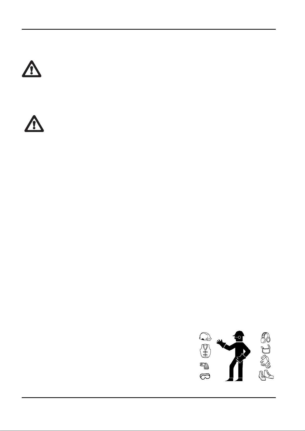
Clothing and protective equipment
Avoid wearing loose clothing, rings, watches or anything
else that may get caught in moving parts.
When using the machine or performing maintenance, wear a
hard hat, glasses, safety footwear, gloves and acoustic ear‑
muffs after making sure these and all other PPE that the
safety manager considers necessary based on the risk analy‑
sis performed are in perfect working condition.
X20JPR0020413
18
BOOM LIFT MODELS X20JPLUS
JLG
ATTENZIONE
DANGER
USE THE TYPE‑APPROVED AND CERTIFIED SAFETY HARNESSES. BEFORE WORKING
AT A HEIGHT, MAKE SURE THAT THE SAFETY HARNESSES ARE CORRECTLY FASTE‑
NED AND CONNECTED TO THE ANCHORAGE POINTS ON THE BASKET.
T
HE USE OF HARNESSES IS COMPULSORY IN ACCORDANCE WITH LOCAL LEGISLATION IN EACH INDI‑
VIDUAL COUNTRY. IN COUNTRIES WHERE THE LAW DOES NOT REQUIRE THE USE OF SUCH SAFETY
SYSTEMS
, THE EMPLOYER AND/OR USER IS RESPONSIBLE FOR CHOOSING THE SYSTEM TO BE USED.
Safety valves and electrical system safety components
It is prohibited to modify and/or tamper with the safety and control valves of the main
hydraulic system and the adjustments of the electric plant. The Constructor is not liable
for injury to persons and damage to objects or to the machine if the standard calibration
of any hydraulic and electric/electronic component is tampered with.
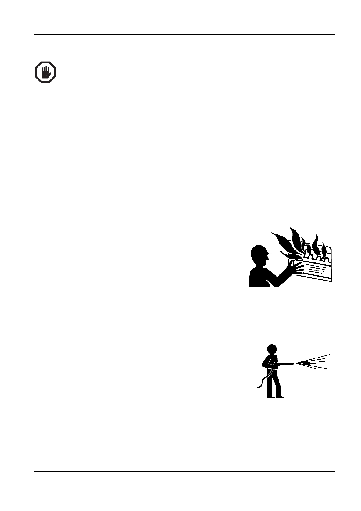
Fire prevention
Keep the area around the motor clean, removing fragments of
wood, paper and other flammable products; clean any fuel
leaks as these may be a potential cause of fire.
Petrol is extremely flammable and explosive in particular con‑
ditions. Refuel in well ventilated areas and with the engine at
rest.
Avoid smoking and producing sparks in the refuelling and
fuel storage area.
After refuelling, make sure to put back the cap correctly. Take care to avoid touching the
exhaust silencer when this is hot, i.e. with the machine running or soon after stopping the
engine.
Preventing damage caused by washing the machine
Do not direct high pressure jets towards the electrical compo‑
nents while washing the machine. Do not use chemical deter‑
gents or petrol that would damage the plastic parts and the
painting.
BEFORE WASHING THE MACHINE, ALWAYS REMEMBER TO REMOVE THE REMO‑
TE CONTROL AND CORRECTLY CLOSE THE REMOTE CONTROL AND EQUIP‑
MENT CONNECTION SOCKETS LOCATED ON THE MACHINE.
X20JPR0020413
BOOM LIFT MODELS X20JPLUS
JLG
19
WARNING
IMPORTANTE
• Cleaning the machine
Always park the machine as shown in the figure in point 2.1.5.
When washing the machine, the ignition block must be disengaged, the key removed and the
emergency stop button pressed.
• Washing the outside of the machine
Never use flammable liquids. Adopt the above safety measures to
prevent sparks due to short‑circuits.
If washing the track with water cleaners, carefully protect all the
important parts and above all the electrical components. Follow the
instructions provided by the manufacturer of the detergent.
Clean the machine using water‑soluble detergents.
The more the elevating platform is cleaned, the more it will need to be greased (see par. 7.3
Grease points).
Do not wet the electric motors and the other electrical components directly. Do not aim the
spray directly onto adhesive labels and rating plates.
• Cleaning the electrical system
Never clean the inverter or the electric motor with water, as this may
cause damage to the electrical system.
X20JPR0020413
20
BOOM LIFT MODELS X20JPLUS
JLG
ATTENZIONE
DANGER
DANGER
DANGER
IMPORTANT
1001125483
ATTENZIONE
ATTENZIONE
1001125483
Only use dry detergents, in accordance with the manufacturer’s instructions. Never remove
covers, guards and the like.
‑ Clean the electrical system using a dry, non‑metallic brush and low pressure air.
• After cleaning
Dry the machine carefully before starting it again (for example using compressed air).
If, despite all the precautions, moisture has penetrated into the electric motor or other parts
of the electric system, these must be dried using compressed air to avoid the risk of short‑cir‑
cuits.
Preventing damage that may be caused by the machine during work
When the machine has been stabilised and work has started, never enter its operating area.
Always operate the controls slowly and smoothly and avoid reversing the movements sud‑
denly.
When operating outside of the basket, ALWAYS keep a MINIMUM distance of 1 METRE
from the machine.
X20JPR0020413
BOOM LIFT MODELS X20JPLUS
JLG
21
WARNING
DANGER
IMPORTANTE
ATTENZIONE
2.3 SAFETY WARNINGS
2.3.1 GENERALITIES
To avoid accidents, before starting work and before performing
any maintenance operations, it is necessary to read, understand
and follow all the precautions and warnings contained in this
manual. The user/operator of the machine must decline all
responsibility for operation until having read this manual and
fully understood how to use the machine under the supervision
of an expert and qualified operator.
Carefully read all the safety messages provided in this manual and the safety signs on the
machine.
Keep the safety signs in good condition and replace them if they are damaged.
Make sure that any new components on the machine are provided with the correct safety signs.
2.3.2 NOISE AND VIBRATIONS
The JLG platforms with electric motor have been tested according to the parameters of Euro‑
pean directive 2000/14 EC, with the guaranteed sound power level measurement shown on
the machine’s EC declaration of conformity.
When operating the aerial part of the machine, this value is reduced even further as the
basket moves away from the main source of noise.
The vibrations transmitted to the operator from the controls and directly from the floor of
the basket are lower than the maximum allowed limits.
BOOM LIFT MODELS X20JPLUS
JLG
22
X20JPR0020413
23
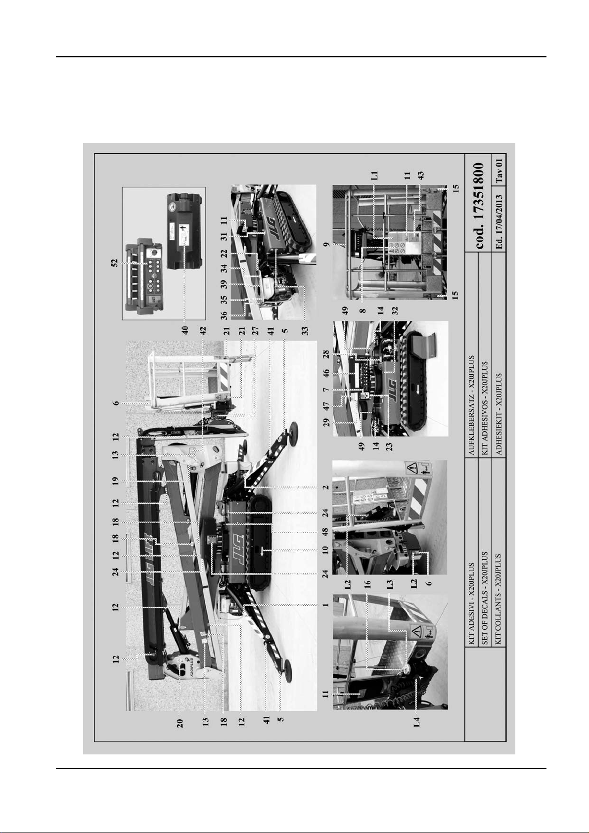
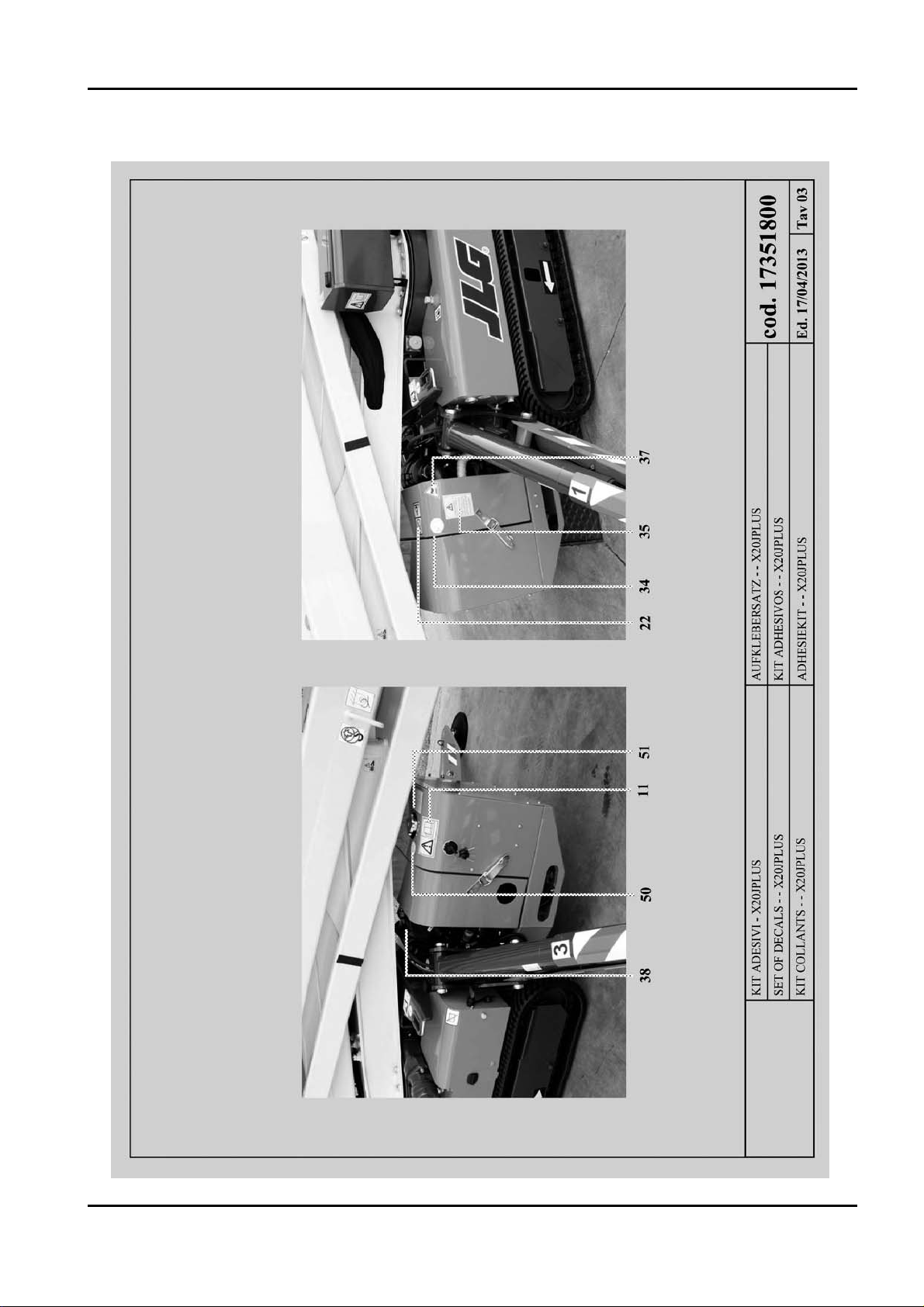
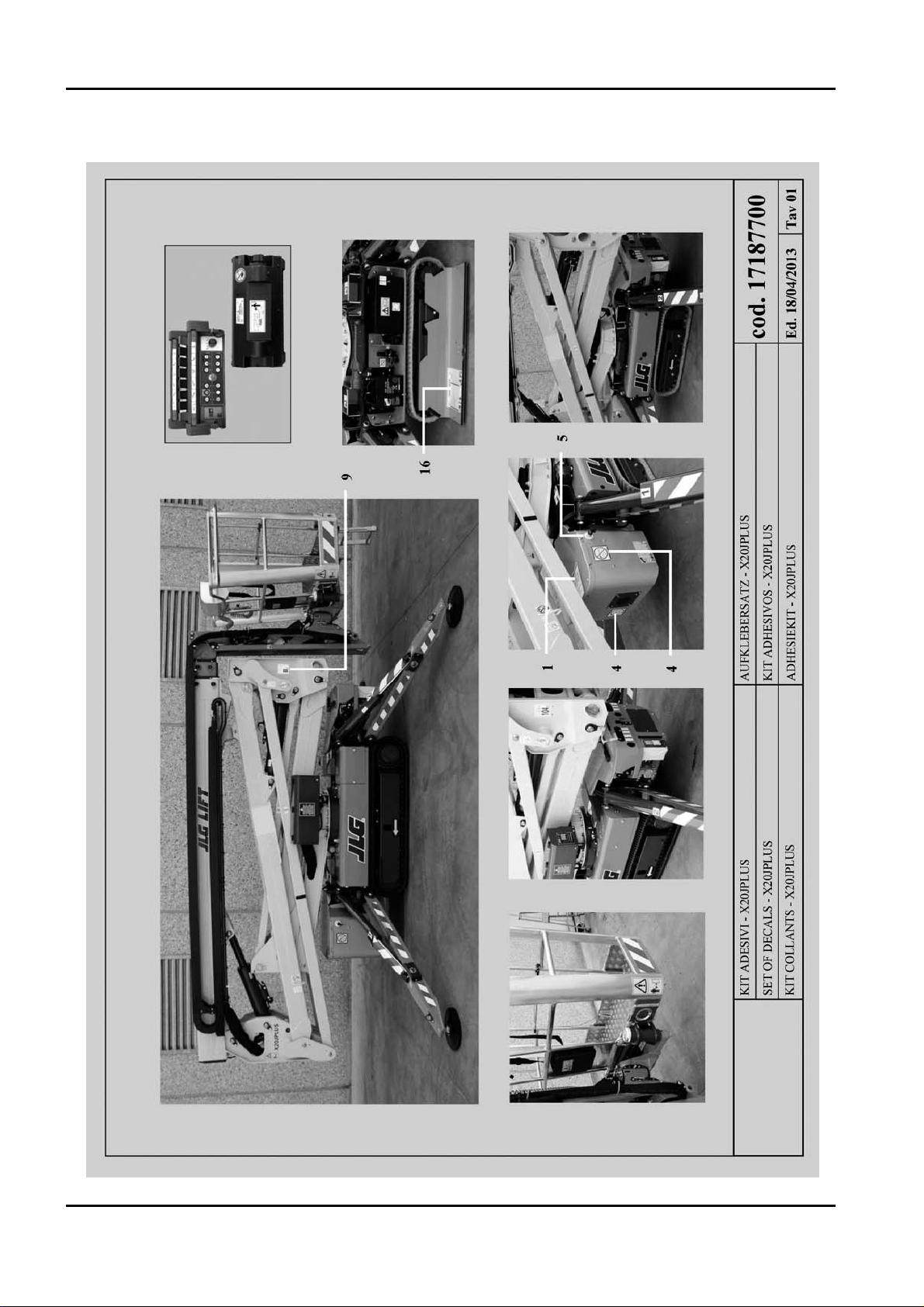
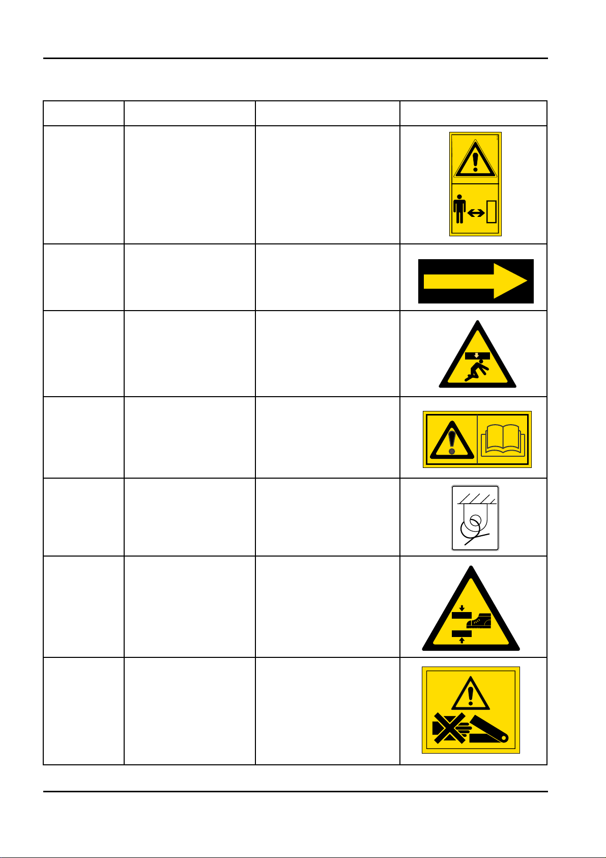
2.3.3 PICTOGRAMS POSITIONED ON THE MACHINE
Here we report the positions of the various boards with pictograms on the machine.
BOOM LIFT MODELS X20JPLUS
JLG
X20JPR0020413
X20JPR0020413
24
BOOM LIFT MODELS X20JPLUS
JLG
X20JPR0020413
BOOM LIFT MODELS X20JPLUS
JLG
25

BOOM LIFT MODELS X20JPLUS
JLG
26
X20JPR0020413
POS. CODE Q.ty
36 1701542 1
36 1701505 1
37 06056300 1
38 06164600 1
39 06232100 1
40 07240300 1
41 07320400 4
42 07034200 2
43 07397200 1
44 1608710001 1
45 1608710002 1
46 07199100 1
47 06254800 1
48 06922700 2
49 07350300 4
50 06214200 1
51 06594500 1
52 07071000 1
53 06136900 1
POS. CODE Q.ty
1 6555500 1
2 6555600 1
3 6555700 1
4 6555800 1
5 6041200 4
6 1001125483 6
7 1706898 1
8 6924300 1
9 1706493 1
10 6040500 2
11 6040900 6
12 6041300 11
13 1703814 4
14 6044000 4
15 6086600 2
16 1704277 2
17 1705828 1
18 7056700 6
19 1701499 2
20 7058800 2
21 6040300 4
22 1706098 1
23 7349200 1
24 7056800 3
25 06086000 1
26 06085900 1
27 06706500 1
28 06998800 1
29 07242000 1
30 1702155 1
31 1701504 1
32 06164700 1
33 06165000 1
34 06060000 1
35 06227200 1

LANGUAGE STICKERS
27
BOOM LIFT MODELS X20JPLUS
JLG
X20JPR0020413
POS. CODE Q.ty
1735181IT
L1 06555300 1
L2 06561200 4
L3 06448200 2
L4 06448100 2
L5 07348900 1
POS. CODE Q.ty
173518GB
L1 06562600 1
L2 06561200 4
L3 06462700 2
L4 06462100 2
L5 073489GB 1
POS. CODE Q.ty
173518FR
L1 06562700 1
L2 06561200 4
L3 06462800 2
L4 06462200 2
L5 073489FR 1
POS. CODE Q.ty
173518DE
L1 06562800 1
L2 06561200 4
L3 06462900 2
L4 06462300 2
L5 073489DE 1
POS. CODE Q.ty
173518ES
L1 06562900 1
L2 06561200 4
L3 06463000 2
L4 06462400 2
L5 073489ES 1
POS. CODE Q.ty
173518NL
L1 06563000 1
L2 06561200 4
L3 06463100 2
L4 06462500 2
L5 073489NL 1
POS. CODE Q.ty
173518PT
L1 06563100 1
L2 06561200 4
L3 06463200 2
L4 06462600 2
L5 073489PT 1
POS. CODE Q.ty
173518NO
L1 07162000 1
L2 06561200 4
L3 07161800 2
L4 07161900 2
L5 073489NO 1
POS. CODE Q.ty
173518DA
L1 07138100 1
L2 06561200 4
L3 07138000 2
L4 07137900 2
L5 073489DA 1
POS. CODE Q.ty
173518SW
L1 07137300 1
L2 06561200 4
L3 07137500 2
L4 07137400 2
L5 073489SW 1
BOOM LIFT MODELS X20JPLUS
JLG
28
X20JPR0020413

29
BOOM LIFT MODELS X20JPLUS
JLG
X20JPR0020413

LANGUAGE STICKERS
BOOM LIFT MODELS X20JPLUS
JLG
30
X20JPR0020413
Pos Code
qty
1
2
3
4
1001125483 3
5
06506400 1
6
7
8
9
06520600 2
17
07264700 1
17
07394800
(from serial number
C170000330)
1
Pos Code
qty
171877IT
1
07188700 1
13
07188100 1
Pos Code
qty
171877GB
1
07201700 1
13
07202100 1
Pos Code
qty
171877FR
1
07201800 1
13
07202200 1
Pos Code
qty
171877DE
1
07188800 1
13
07188200 1
31
BOOM LIFT MODELS X20JPLUS
JLG
X20JPR0020413
Pos Code
qty
171877ES
1
07201900 1
13
07202300 1
Pos Code
qty
171877NL
1
07188900 1
13
07188300 1
Pos Code
qty
171877PT
1
07202000 1
13
07202400 1
Pos Code
qty
171877SW
1
07189000 1
13
07188400 1
Pos Code
qty
171877DA
1
07189100 1
13
07188500 1
Pos Code
qty
171877NO
1
07189200 1
13
07188600 1
X20JPR0020413
32
BOOM LIFT MODELS X20JPLUS
JLG
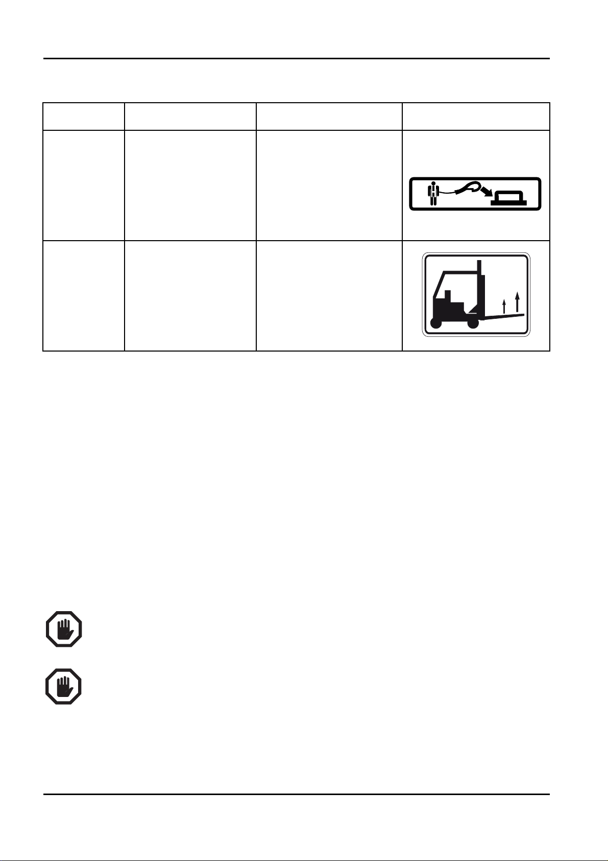
Code Name Description Identikit
06040300
WARNING KEEP
SAFE DISTANCE
06040500
SENSE OF MOVING
UNDERCARRIAGE
DEFINED AS THE
DIRECTION FORWARD
06040800
CRUSHING HAZARD
PERSON
06040900
OBLIGATION TO
READ THE MANUAL
BEFORE USE OF
MACHINE
1703814
FIXING POINT FOR
TRANSPORT
INDICATES CORRECT
FIXING POINT FOR
TRANSPORT OF THE
MACHINE
06041200
CRUSHING HAZARD
FEET
INDICATES AREAS
WHERE THERE IS A
DANGER OF CRU‑
SHING LOWER LIMBS
FOR THE OPERATOR
06041300
CRUSHING HAZARD
PERSON
INDICATES AREAS
WHERE THERE IS A
DANGER OF CRU‑
SHING UPPER LIMBS
FOR THE OPERATOR
06040300
06040500
06040800
06040900
1703814A
06041200
06041300
X20JPR0020413
BOOM LIFT MODELS X20JPLUS
JLG
33
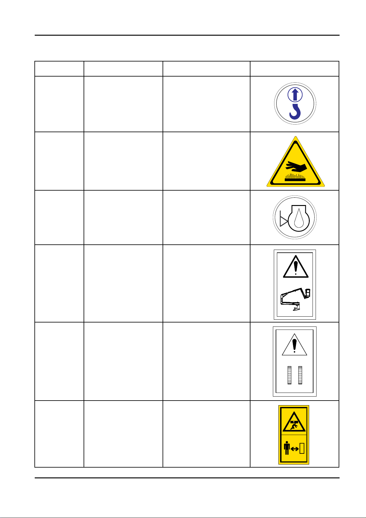
Code Name Description Identikit
06044000 LIFTING POINT
INDICATES CORRECT
LIFTING POINTS FOR
LIFT THE MACHINE
06056300
DANGER HIGHT
TEMPERATURE
06060000 ENGINE OIL LEVEL
06085900
EMERGENCY DEVI‑
CE FOR AERIAL
PART
DEVICE THAT ALLOWS
TO EXCLUDE THE
SAFETY OF THE
AEREAL PART IN CASE
OF EMERGENCY OPE‑
RATIONS
06086000
EMERGENCY DEVI‑
CE FOR UNDERCAR‑
RIAGE
DEVICE THAT ALLOWS
TO EXCLUDE THE
SAFETY OF THE
UNDERCARRIAGE IN
CASE OF EMERGENCY
OPERATIONS
06086600
WARNING KEEP
SAFE DISTANCE
AND CRUSHING
HAZARD PERSON
0
6
0
4
4
0
0
0
06056300
0
0
0
0
6
0
6
0
06085900
06086000
06086600

BOOM LIFT MODELS X20JPLUS
JLG
34
X20JPR0020413
Code Name Description Identikit
06165000
HYDRAULIC OIL
LEVEL
06311200
FORBIDDEN
LIFTING POINT
1001125483
DO NOT WASH
WITH WATER
06560500 GROUNDING
06998800
HAND PUMP
LEGEND
QUICK INSTRUCTIONS
FOR USING THE EMER‑
GENCY HAND PUMP
06924300
BE CAREFULL AT
WORK
USING SAFETY HARNES‑
SES, USE PROTECTIVE
EQUIPMENT (HELMET),
PROHIBITION OF WELD
ON THE MACHINE,
PROHIBITION OF USE
SYSTEMS TO INCREASE
THE AREA OF WORK
INSIDE THE BASKET ,
PROHIBITION OF
WORKING IN THE VICI‑
NITY OF VOLTAGE ELEC‑
TRIC, PROHIBITION OF
USE OF THE PLATFORM
FOR RAISING LOADS
0
6
3
1
1
2
0
A
0
0
0
5
6
1
6
0
1001125483
06560500
06998800A
0692430006924300

35
BOOM LIFT MODELS X20JPLUS
JLG
X20JPR0020413
Code Name Description Identikit
07107200
BATTERY
PACK WARNINGS
CORROSIVE LIQUID
Presence of highly corrosi‑
ve liquid, dangerous to
the body and eyes.
HIGH VOLTAGE
Presence of high voltage
with danger of electric
shock.
DANGER OF
EXPLOSION
Formation of potentially
explosive mixture inside
the battery.
NO NAKED FLAMES
Do not smoke or use
naked flames when
recharging and near the
vehicle. Risk of explosion.
RECYCLING
It is highly recommended
to comply with legislative
and environmental stan‑
dards as regards the
demolition, reuse, recy‑
cling and recovery of
materials.
REPLACE STICKERS AND PLATES IF THERE IS ANY SIGN OF WEAR.
FAILURE TO HEED ANY WARNINGS DUE TO A SAFETY STICKER BEING DAMAGED,
LOST OR IGNORED MAY CAUSE SERIOUS ACCIDENTS.
X20JPR0020413
36
BOOM LIFT MODELS X20JPLUS
JLG
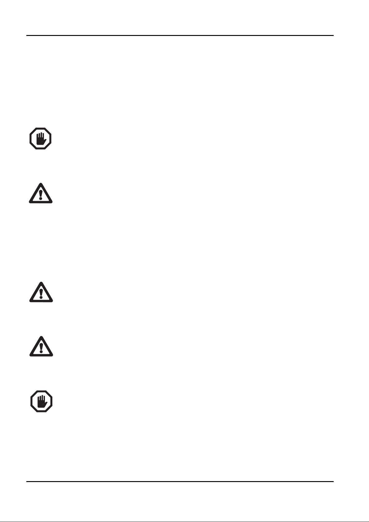
Code Name Description Identikit
1704277
ANCHOR
POSITION
IN BASKET
INDICATES THE POSI‑
TION OF THE ANCHOR
HOOKS TO WHICH
FASTEN THE OPERA‑
TOR’S SAFETY SLING
07350300
LIFTING POINTS
WITH FORKLIFT
INDICATES THE LIF‑
TING POINTS WITH
FORKLIFT
1704277A
07350300A

37
BOOM LIFT MODELS X20JPLUS
JLG
X20JPR0020413
3 SAFETY DEVICES
The information given below concerning the safety devices are provided to the user in order
to allow him/her to understand the machine behaviour and possible work sequences; moreo‑
ver, in this way it is possible to identify any breakdowns with greater precision and to sup‑
ply more detailed information to the after‑sales service for quicker, less expensive interven‑
tions.
The machine is fitted with safety devices used to prevent dangerous situations for the opera‑
tor. It is important that before starting any operation, the operator checks the perfect working
order of these devices.
The non‑functioning of a safety device, whether caused by a fault or tampering, can cause
serious damage to the machine and consequently put the operator’s life at risk. The Con‑
structor has designed the machine and safety devices in order to guarantee the maximum to
its customers, however the devices must be checked periodically according to that described
in this manual and they must never be tampered with.
The service function on the remote control can be used as an aid for checking electric safety
devices.
Never intervene on the safety devices. If they are tampered with, the manufacturer declines
all liability regarding any accidents that may be due to such tampering.
It is prohibited to tamper with the lead sealing or setting of the maximum pressure valves
and the adjustments of the electrical components. If they are tampered with the manufactu‑
rer declines all liability for any accidents that may be due to such tampering.
The Constructor is not liable for any damage/injury caused by the machine to objects and/or
persons due to failure to comply with the above instructions.
BOOM LIFT MODELS X20JPLUS
JLG
38
X20JPR0020413

39
3.1 BATTERY CUTOUT SWITCH
This device, located on the left side of the electrical components compartment, is used to iso‑
late the machine’s electrical circuit, stopping any movements. It is well‑visible and easily
accessed without using tools. It only needs to be activated for prolonged machine downtime
or maintenance operations.
Turning the key clockwise closes the machine’s electrical circuit, while turning it anticlockwi‑
se isolates the machine’s electrical circuit and the key can be removed.
B
EFORE DISCONNECTING THE BATTERY BY MEANS OF THIS DEVICE, MAKE SURE THAT THE ENGINE
KEY IS IN POSITION
“OFF” AND THE REMOTE CONTROL AND ELECTRONIC BOARD ARE OFF.
3.2 DISTRIBUTOR PRESSURE RELIEF VALVES
All platform distributors have a pressure relief valve that limits the pressure inside the
system to the value set for the same valve.
These valves are set when the platform is tested by qualified personnel and must not be tam‑
pered with for any reason whatsoever.
BOOM LIFT MODELS X20JPLUS
JLG
X20JPR0020413
THERMIC MOTOR
LITHIUM MOTOR
WARNING
IMPORTANTE
3.3 CYLINDER STOP VALVES
The stabiliser cylinders have a double stop valve which in case of system breakdown or hose
breakage stops the cylinder preventing dangerous platform instability situations.
All cylinders that move the aerial part of the platform structure are fitted with a stop valve
which in case of system breakdown or hose breakage stops the cylinder preventing the
basket from falling due to gravity.
These valves are calibrated in the platform inspection phase by the constructor and must
not be tampered with for any reason.
3.4 ALIGNMENT PHOTOCELLS ON THE AERIAL PART OF THE STRUCTURE AND
THE BASE OF THE MACHINE
The platform has two safety photocells that ensure that the aerial part of the machine is com‑
pletely lowered and aligned with the base and that the telescopic arm is completely retrac‑
ted.
When these conditions are not met, a signal is sent that disables the movement of the stabili‑
sers.
BOOM LIFT MODELS X20JPLUS
JLG
40
X20JPR0020413
41
3.5 STABILISER POSITION MICROSWITCHES
The position of the stabilisers and their contact with the ground are detected by 4 microswit‑
ches positioned near the stabiliser cylinder rod fastening pin. The microswitches fixed to the
stabiliser must be released when the stabiliser rests on the ground.
Check the correct operation of the microswitches every day.
3.6 JIB POSITION MICROSWITCH
The position of the jib arm is detected by a microswitch that is secured to the jib arm itself.
The microswitch must be released when the jib arm is closed.
Check the condition and correct operation of the JIB microswitch every day.
BOOM LIFT MODELS X20JPLUS
JLG
X20JPR0020413

3.7 BASKET LOAD SENSOR
The load sensor on the basket is made up of a basket sup‑
port with two shafts that only allow the vertical move‑
ment of the basket. The basket support is supplied by the
load cell itself. Two strain gauges are positioned inside the
sensor positioned under the basket and convert the relati‑
ve weight inside the basket into an electrical signal.
The electrical signal is then sent to the electronic board,
which processes it and identifies any dangerous condi‑
tions.
The remote control display always shows the maximum load allowed according to the work
mode.
When the maximum allowable load is reached, an icon appears on the remote control
display, a sound signal is emitted and all platform movements are disabled.
To restore platform operation the excess weight must be removed in order to return below
the maximum allowable weight (see paragraph on the display).
The Constructor recommends that maximum attention is paid to
the conditions of all safety components and in particular of the
system that makes up the basket load sensor; always check cor‑
rect operation whenever objects are struck with the basket or if
performing operations that may damage the system (e.g. pru‑
ning, painting etc.).
Before any elevating manoeuvre, always make sure that the two closing covers on the ver‑
tical pins are completely screwed in.
BOOM LIFT MODELS X20JPLUS
JLG
42
X20JPR0020413
COVER
DANGER
DANGER
ATTENZIONE
PERICOLO
3.8 CONTROL PROTECTION
A protection structure is provided to protect the remote control against the accidental fall of
objects from above and involuntary activation by the operator.
Always make sure that this protection structure is intact before using the machine.
3.9 SPIRIT LEVEL
The spirit level is positioned on the turret and it is readily visi‑
ble from the basket and from the ground. The spirit level must
be used to make sure that during the platform levelling phase
the maximum allowable gradient of 1° is complied with. This
condition is met when the air bubble is inside the green area.
A second electronic spirit level contained in the control board
makes sure that this condition is effectively satisfied and checks the power supply to the con‑
trols for the aerial part.
Always check the correct levelling of the machine after every self‑levelling operation.
Approximate levelling outside of the limits set by the manufacturer is very dangerous and
can affect the stability of the platform, which represents a risk, even deadly, for the operator
and other persons working on the machine and near it.
Never intervene on the spirit level adjustments; this device is calibrated by the Constructor
during the inspection before sale. Only technicians authorised by the Constructor and in pos‑
session of suitable tools can intervene on the spirit level.
X20JPR0020413
BOOM LIFT MODELS X20JPLUS
JLG
43

3.10 PIN LOCKING BOLTS AND NUTS
All the pins used on the JLG platform were treated against wear and are fitted with flanges
(1) to prevent them from rotating inside their seat. Some pins have bolts to stop rotation (2)
while others pins have a joint in the structure of the machine.
The pins in the most delicate positions are threaded at the ends and are fitted with self‑
locking nuts (3) or self‑locking threaded ring nuts to prevent the structure from subsiding.
Check the correct tightness of all the pin locking devices according to the intervals indicated
by the manufacturer of the machine.
Never loosen the pin locking devices and periodically check they are correctly tightened. A
pin that comes off its housing, even partially, may cause unexpected and uncontrollable
movements and even cause the machine to lose stability and/or the basket to fall.
3.11 SAFETY DEVICE ELECTRONIC CONTROL BOARD
The JLG platform has an electronic control board (see
photo) that enables the power supply to the ON‑OFF pro‑
portional coils after verification of the safety conditions by
the sensors positioned on the machine.
The control procedure on the electronic board may be
bypassed using the key selector switch with spring return:
“safety device bypass key”.
The electronic board records every bypass action carried
out by the operator on the safety devices, filing them by
date, time and lapse of time during which the operator held the “safety device bypass key”
in position.
The board is also provided with an event record that stores all the operations performed on
the machine for a variable period of time.
BOOM LIFT MODELS X20JPLUS
JLG
44
X20JPR0020413
1
2
3

45
BOOM LIFT MODELS X20JPLUS
JLG
X20JPR0020413

4 INSTRUMENTS AND CONTROLS
Below is a description of all the controls and indicators present on the platform; each device
has a sticker that briefly describes its function applied nearby, often containing symbols that
are used to ensure quick and clear understanding. Before using the platform, the following
descriptions must be read in order to gain in‑depth knowledge of the functions of each devi‑
ce and to be aware of any suggestions provided by the manufacturer.
Before starting to use the platform, the operator must read and perfectly understand all the
instructions contained in this manual.
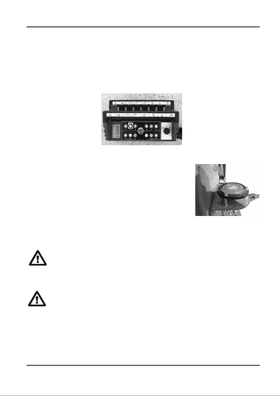
4.1 REMOTE CONTROL
The remote control contains most of the controls required for normal operation of the machi‑
ne.
The remote control is made up of buttons, joysticks, a key selector switch and a display.
The remote control continuously exchanges data with the machine’s main board, which in
turn transmits the information to be shown on the display.
X20JPR0020413
46
BOOM LIFT MODELS X20JPLUS
JLG
07071000B
56
4.1.1 DISPLAY
The display is used to view the status of the machine and the operating information neces‑
sary or useful for the operator.
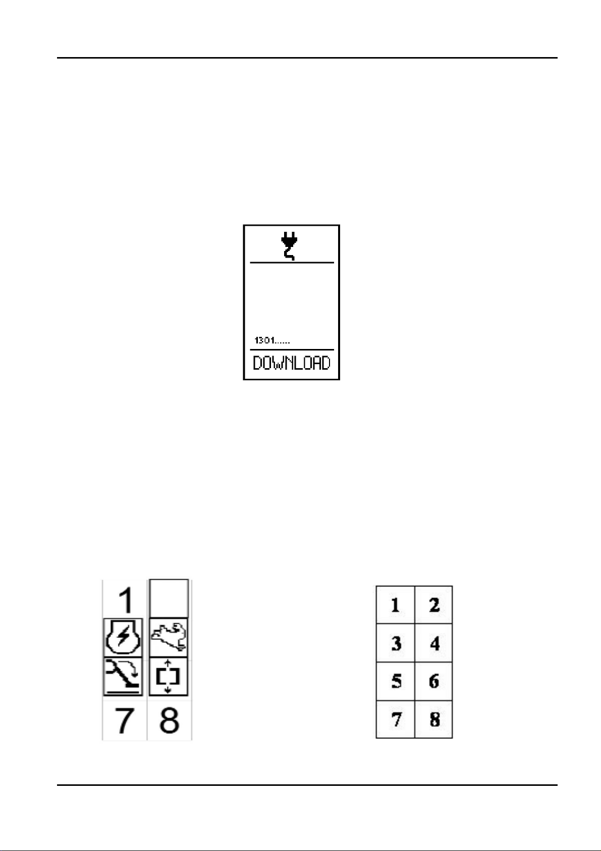
When the machine’s main control board is powered via the engine key, the information to be
shown on the display is sent to the remote control.
This operation has a variable duration. Normally a few seconds are sufficient, however the
following screen may appear on the display:
In this case about 5‑10 minutes are needed to send all the information from the main board
to the remote control. The machine cannot work during this period.
Do not stop the machine or operate it during this period.
4.1.1.1 DISPLAY MAIN SCREEN
When the machine is started, the main screen is displayed, giving a general overview of the
machine status. For the sake of simplicity and clarity a layout is provided with 8 icon display
positions.
Example of the main screen: Icon position diagram:
X20JPR0020413
BOOM LIFT MODELS X20JPLUS
JLG
47
POSITION 3:
Position 3 displays the engine/motor selection and the engine status.
Petrol/diesel engine Electric motor
An X on the icon indicates that the engine/motor is off, no X indicates that it is on.
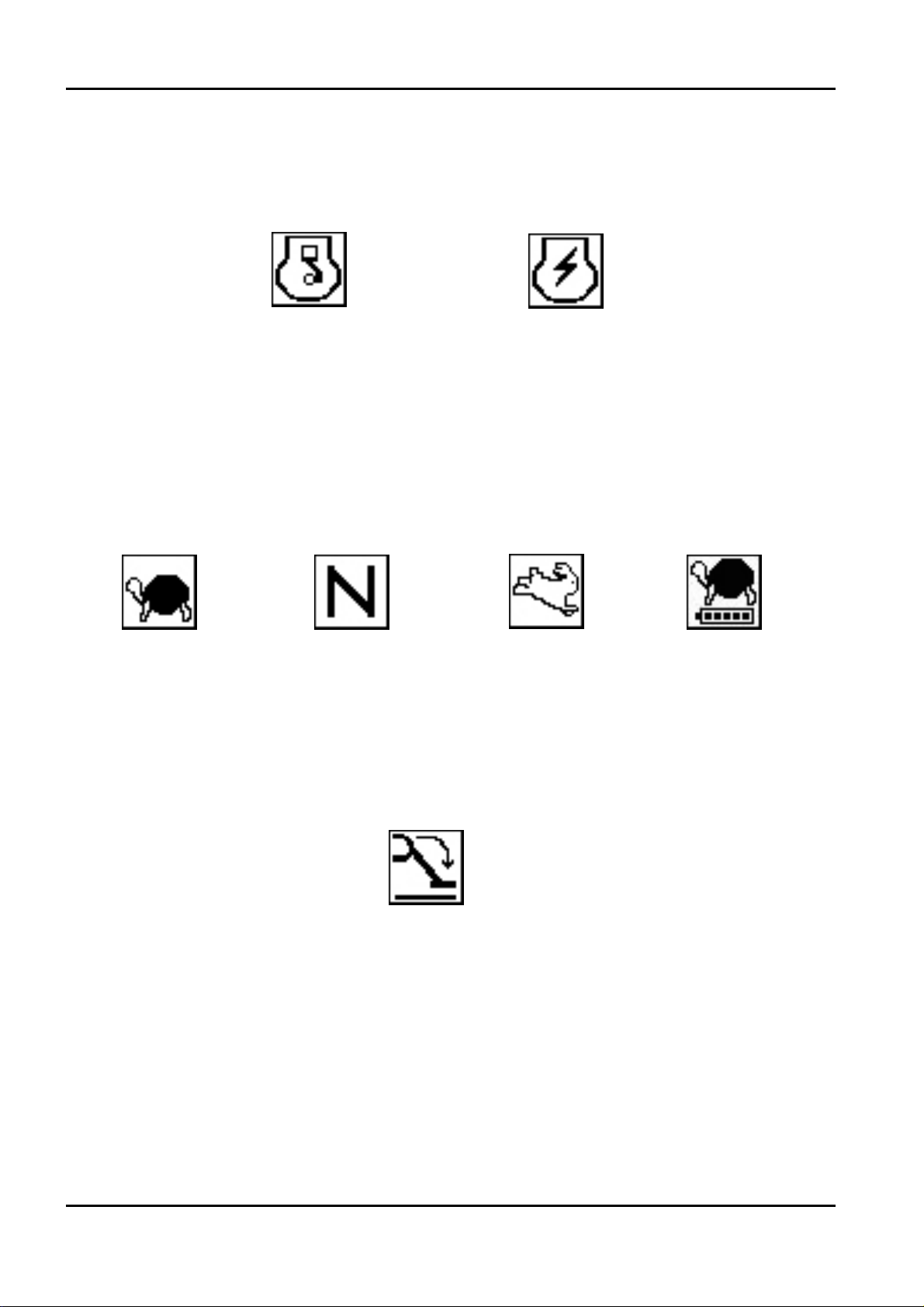
POSITION 4:
Position 4 displays the selected speed or the reduced speed for the Lithium:
SLOW NORMAL FAST REDUCED
POSITION 5:
Position 5 displays the icon confirming that overhead movements are enabled.
This icon means that all conditions for using the overhead movements have been checked
and the aerial part can be lifted. No icon on means that the aerial part cannot be lifted.
In place of this icon, the basket overload icon may be shown.
X20JPR0020413
48
BOOM LIFT MODELS X20JPLUS
JLG

When the load sensor measures a load exceeding the allowed work load ‑ 230 kg ‑ the main
screen disappears for three seconds, replaced by the overload error display, the audible war‑
ning is activated, then the overload icon appears in position 5 in place of the icon enabling
the overhead movements.
OVERLOAD ERROR DISPLAY
POSITION 6:
Position 6 displays the icon confirming that track movements (stabilisers, tracks, track exten‑
sion) are enabled.
This icon means that all conditions for operating the track movements have been checked.
No icon on means the stabilisers cannot be used and the track cannot be extended. The
machine, however, can travel even when the icon is off, as long as all 4 stabilisers are lifted
from the ground.
X20JPR0020413
BOOM LIFT MODELS X20JPLUS
JLG
49
POSITION 7:
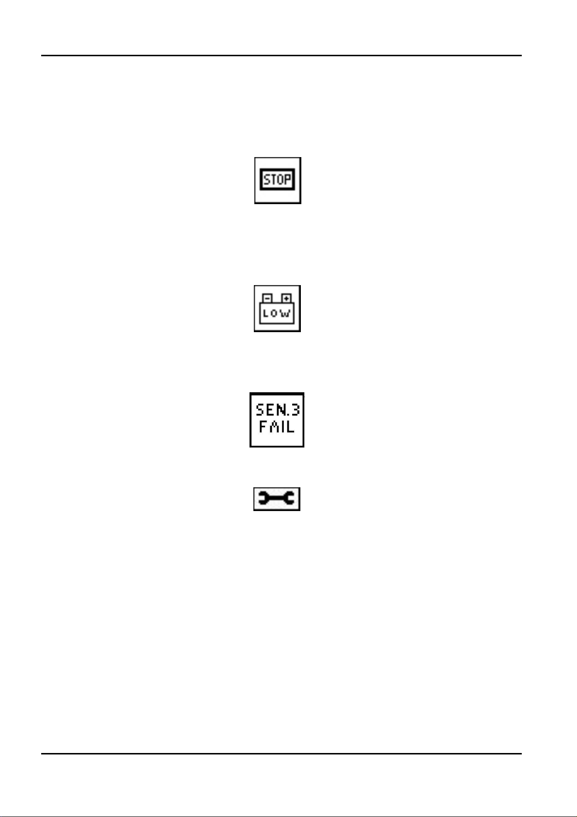
Position 7 is used for functional signals:
Emergency STOP pressed
Signals that one of the emergency stop buttons on the machine has not been released.
BATTERY VOLTAGE BELOW MINIMUM LIMIT.
Indicates that the battery charge level is below the minimum limit allowed. If this message
appears, it is advisable to recharge the battery, either by keeping the diesel or petrol engine
on, or by connecting to the network.
Signals an error in the battery management system of Lithium version.
In this position also other functional signals can be displayed that are useful for machine dia‑
gnostics.
X20JPR0020413
50
BOOM LIFT MODELS X20JPLUS
JLG

POSITION 8:
Position 8 displays the battery charge status or the icon indicating the battery is being
recharged in the Lithium version.
Position 8 is used to show the selection of the emergency descent operation from the basket
with solenoid valves on the cylinders.
In addition to the main screen described above, there are other functional displays that
will be described successively.
4.2.1 JOYSTICKS
Using the joysticks the operator selects the movement to be performed, the direction and the
speed. The direction of the joystick determines the direction of the movement. The degree of
movement of the joystick determines the speed. The more the joystick is moved away from
the central neutral position, the faster the movements obtained.
Starting from the left in the figure shown below, the joysticks are numbered from 1 to 8. The
following table shows the movement controlled and its direction depending on the joystick
shifting direction.
The angular position control does not work correctly
The machine has a CANBUS line connection fault.
A faulty or incorrect electronic board (card) has been installed, or alter‑
natively an incorrect software version has been loaded.
X20JPR0020413
BOOM LIFT MODELS X20JPLUS
JLG
51
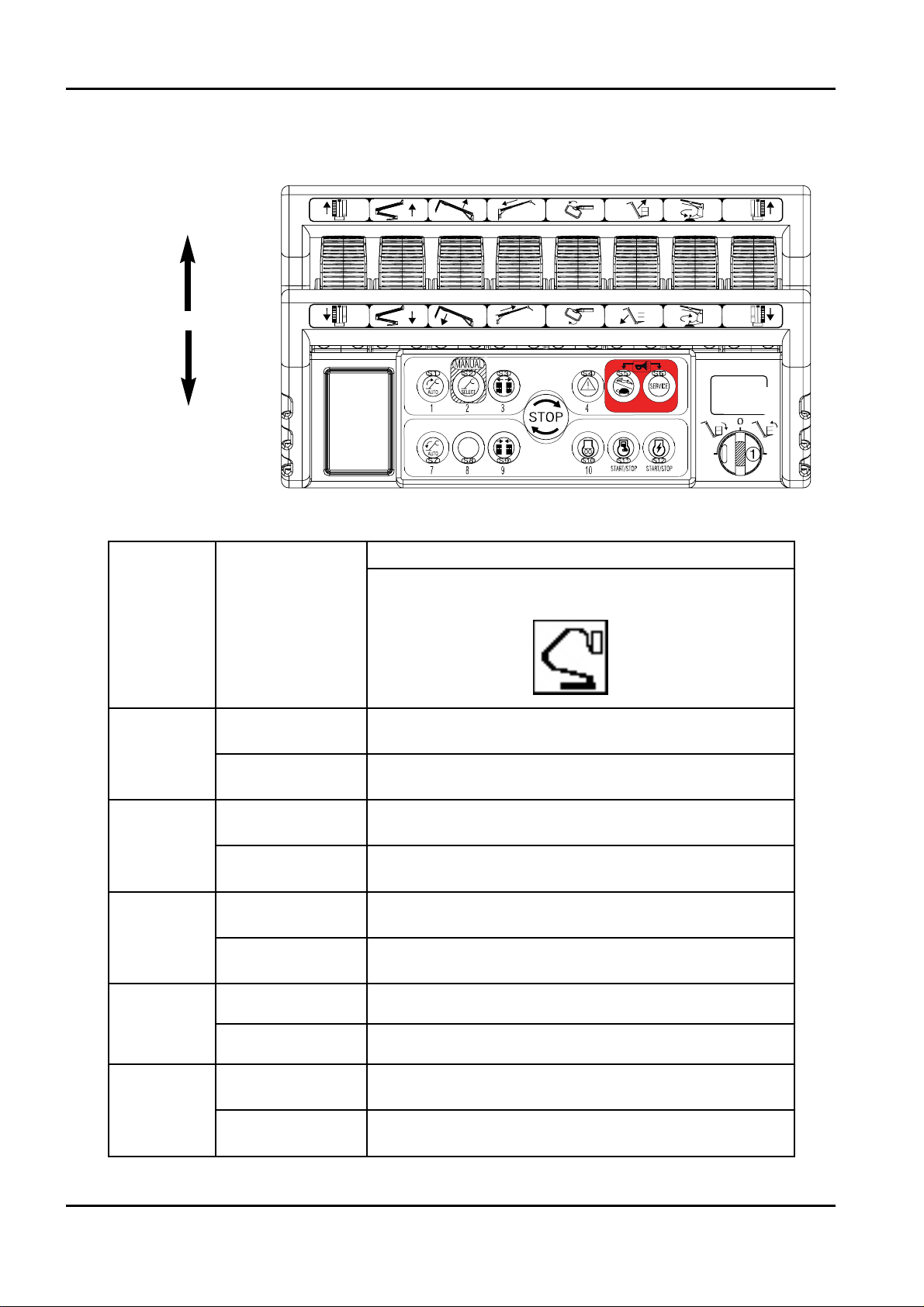
FORWARDS
BACKWARDS
JOYSTICK
JOYSTICK
SHIFTING
DIRECTION
MOVEMENT CONTROLLED
AERIAL MOVEMENTS ENABLED
1
FORWARDS LEFT TRACK FORWARDS
BACKWARDS LEFT TRACK BACKWARDS
2
FORWARDS 1st‑2nd ARM UP
BACKWARDS 1st‑2nd ARM DOWN
3
FORWARDS 3rd ARM UP
BACKWARDS 3rd ARM DOWN
4
FORWARDS EXTENSION ARM IN
BACKWARDS EXTENSION ARM OUT
5
FORWARDS BASKET ANTICLOCKWISE ROTATION
BACKWARDS BASKET CLOCKWISE ROTATION
1 2345678
9
X20JPR0020413
52
BOOM LIFT MODELS X20JPLUS
JLG
07071000B
56

4.1.3 PUSH BUTTONS
The buttons have a dual function: they can be used to select machine functions or as numeri‑
cal keys in the service submenus.
They in fact feature an icon that represents their meaning and a number for use as a numeri‑
cal keypad.
An emergency STOP button is also available which, when pressed, stops the motor and
brings the machine to a standstill.
The pressed position of the emergency STOP button is represented on the display in position 7.
To make the machine operational again, the button must be turned and released.
For the description of the individual functions, see paragraph 6 Using the machine.
BUTTON 1:
Used to automatically raise the stabilisers.
6
FORWARDS JIB OPENING
BACKWARDS JIB FOLDING
7
FORWARDS ANTICLOCKWISE ROTATION
BACKWARDS CLOCKWISE ROTATION
8
FORWARDS RIGHT TRACK FORWARDS
BACKWARDS RIGHT TRACK BACKWARDS
9
R CLOSE BASKET LEVELLING
L OPEN BASKET LEVELLING
X20JPR0020413
BOOM LIFT MODELS X20JPLUS
JLG
53

BUTTON 2:
Enters the menu for the manual movements of the individual stabilisers.
BUTTONS 3‑9:
Used to extend and narrow the tracked undercarriage.
BUTTON 4
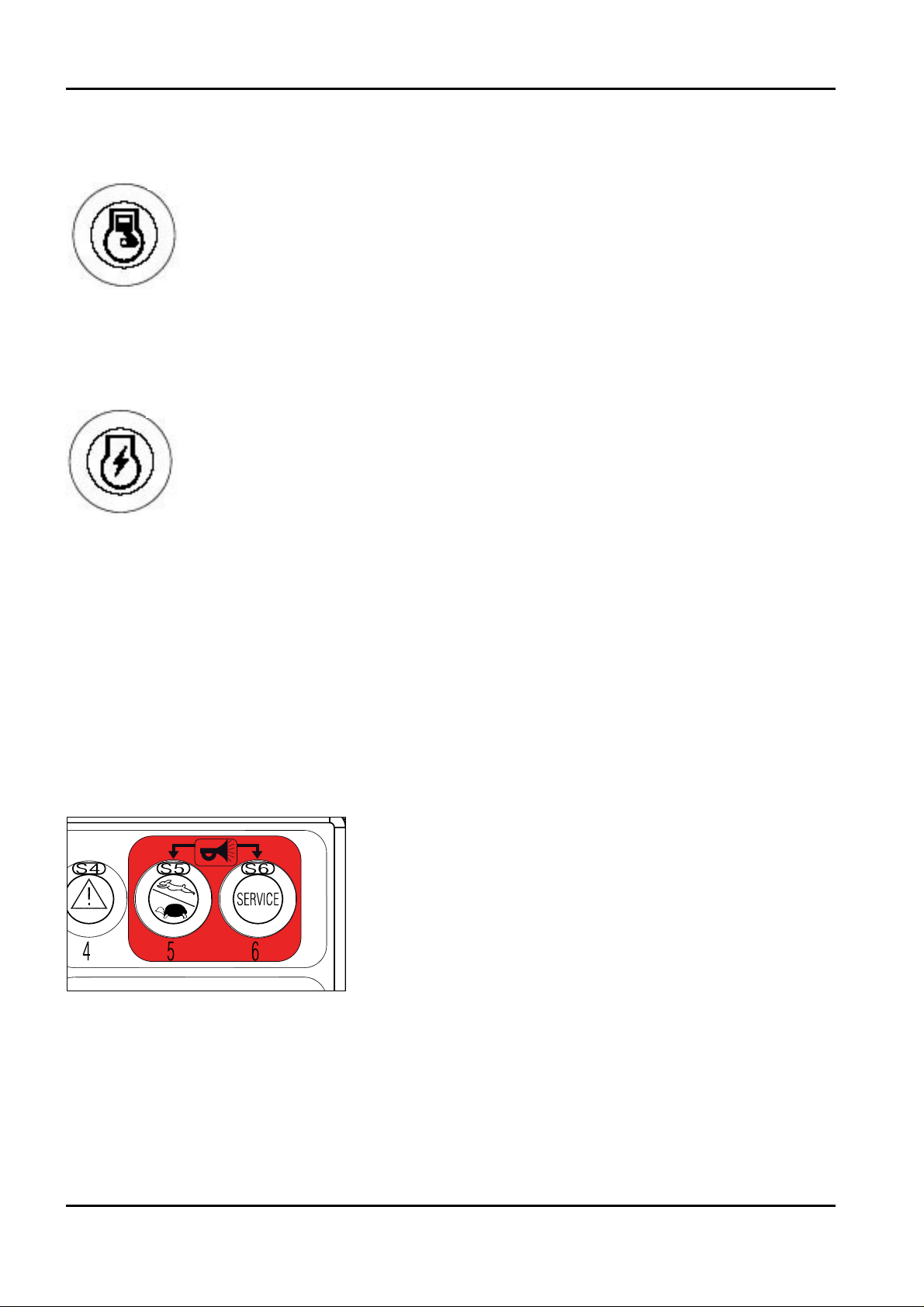
Used to enable control of the emergency descent from the basket. Confirmation that the ope‑
ration is enabled is displayed on the screen in position 8.
BUTTON 5:
Used to select the travel speed and the engine/motor speed.
There are three speeds available:
• SLOW
: engine at 1,500 rpm for the operation of the aerial part, at 2,200 rpm for the operation of
the carriage. Minimum possible speed for the tracks.
• NORMAL:
variable rpm according to the selected movement. Travel motors always with maxi‑
X20JPR0020413
54
BOOM LIFT MODELS X20JPLUS
JLG

mum displacement, therefore medium travel speed
• FAST:
variable rpm according to the selected movement. Travel motors in automatic displacement
variation mode, therefore maximum travel speed.
The three speeds are selected by pressing button 5 in sequence, with a cyclical routine. The
selected speed is displayed on the screen in position 4.
BUTTON 6:
Enters the auto service menu (see paragraph 9 Remote control service menu).
BUTTON 7:
Used to automatically lower the stabilisers.
BUTTON 10:
PETROL ENGINE
Allows the preheating of the petrol engine. One pressure on the button sets the engine at
2200 rpm for 20 seconds, in order to heat the engine and improve the initial phases of use.
DIESEL ENGINE
Enables the activation of the sparking plugs preheating. One pressure on the button causes a
preheating equal to 10 seconds. In case of anticipated starting, the preheating ends when
starting.
X20JPR0020413
BOOM LIFT MODELS X20JPLUS
JLG
55
BUTTON 11:
Allows the engine to be switched on/off. If the button is pressed with the engine on, this will
be stopped.
BUTTON 12:
Allows the electric motor to be switched on/off. If the button is pressed with the engine on,
this will be stopped.
If the start buttons are pressed with an emergency STOP button pressed, starting will be
impossible.
This condition is indicated by the icon STOP in position 7.
If the operator attempts to start one of the two motors while the other is already running,
starting will be impossible and the icon showing the motor already on will appear at the cen‑
tre of the screen.
Note:
Buttons 5 and 6 when pressed simultaneously also activate the horn (optional).
X20JPR0020413
56
BOOM LIFT MODELS X20JPLUS
JLG
07071000B
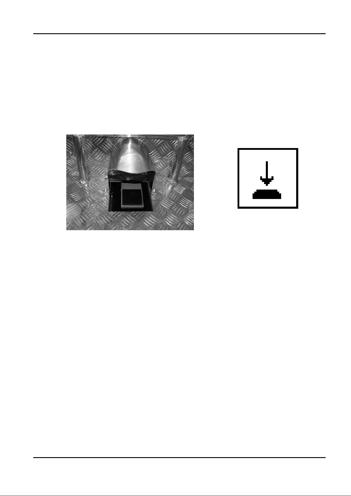
X20JPR0020413
BOOM LIFT MODELS X20JPLUS
JLG
4.2 FOOTSWITCH (OPTIONAL)
Inside of the basket is fitted a footswitch device that must be pushed to allow the movement
of the machine from the basket. If you try to move the machine without the footswitch
pushed the movement will be prohibited and a message on the display will appear infor‑
ming that it is necessary push the pedal to work. If you have not made moves to 7 seconds
after pressing the pedal this must be release and pressed again to resume work.
4.3 CONTROL POSITIONS
See paragraph 2.1.1 Control position.
57

5 EMERGENCY DEVICES
The following information concerning the emergency devices is provided to help understand
the behaviour of the machine and the possible work sequences; moreover, the devices can
thus be identified more clearly and quicker action can be taken if emergencies occur.
It is important that before starting any operation the operator checks the perfect
working order of the emergency devices.
5.1 EMERGENCY STOP BUTTON
Allows immediate shutdown of all machine functions in emergency conditions.
The machine is provided with two emergency stop devices: the first is located on the carriage
just above the turntable, the second on the remote control. Once the device has been activa‑
ted, the button must be turned and released to allow the machine to operate again.
Selection of the emergency stop is indicated on the remote control display.
It is strongly recommended to comply with the rule whereby the platform must not be ope‑
rated without personnel available on the ground. Indeed, accidental operation (e.g. due to a
falling branch) or voluntary operation of the emergency button by unauthorised persons on
the ground would put the occupants of the basket in the unpleasant situation of not being
able to perform any movements, except descent using the emergency descent devices.
ON REMOTE CONTROL
X20JPR0020413
58
BOOM LIFT MODELS X20JPLUS
JLG
ON TRACK
WARNING
IMPORTANTE

5.2 HAND PUMP
The hand pump (2) is used to pressurise oil for emergency movements made necessary by
any breakdown of the main hydraulic system.
The hand pump has a manual switch (1) used to select whether to control the two left stabili‑
sers (Position A) or to control the two right stabilisers and the aerial part of the structure
(Position B).
5.3 SOLENOID VALVES FOR EMERGENCY DESCENT
The cylinders of the first‑second arm, of the third arm and the jib
have a solenoid valve for emergency descent (1). Activating the
emergency descent button on the remote control energises these
solenoid valves, which allow the descent of the aerial part of the
structure due to gravity.
The use of this emergency device depends on the platform’s
electrical system being powered.
1
X20JPR0020413
BOOM LIFT MODELS X20JPLUS
JLG
59
B
1
2
A
06998800A

5.4 SAFETY DEVICE BYPASS KEY
The machine has a key device that acts on the electrical circuit, bypassing the platform safety
systems. The device is situated on the cover of the electrical components compartment.
The use of this selector switch is illustrated in the following paragraphs on how to use the
machine.
Considering the hazard deriving from the use of the platform during the bypass of the
safety devices, carefully read the paragraphs regarding the use of the safety device release
key selector switch.
The key used to activate the safety device bypass is lead‑sealed on the side of the electrical
components compartment near the battery.
Force the lead‑sealing to remove it. After using the safety device bypass a JLG after‑sales
centre must be contacted in order to verify the causes that determined the need to use the
safety device bypass and to lead‑seal the key.
The safety device electronic control board records when the safety device bypass key is
used and the movements carried out during these operations.
The safety device bypass system is used to move the machine with a higher load than the
limit load allowed inside the basket; the overload alarm is nonetheless displayed and the
beeper warns the operator of the dangerous conditions. This device must only be used by
expert personnel trained on how to use the machine, while the end user, who does not
fully know the machine’s operating principles, is not allowed to use this device.
X20JPR0020413
60
BOOM LIFT MODELS X20JPLUS
JLG

5.5 EMERGENCY POSITION CONTROLS
‑ SELECTION PANEL, EMERGENCY STOP AND STARTING
This panel houses the following controls:
‑ Three‑position control for selecting the control position.
1_The central (neutral) position of the selector enables the use of the primary remote
control in the basket.
2_Turning clockwise and holding it in position enables the emergency control position
and energises the main proportional valve on the hydraulic system for moving the arms.
On the Lithium version, it also starts the electric motor. The main proportional valve can
only be enabled if all the conditions that allow the movement of the aerial part have
been satisfied.
This is signalled by the icon on the remote control in position 5, and repeated on this
panel by the green light coming on (see photo).
3_Turning anticlockwise enables the control position for maintenance using the remote
control on the ground; this option can only be used for maintenance operations and for
it to be enabled the primary remote control must be in the basket or the remote control
cable in the basket must be connected to the special adapter.
‑ Emergency STOP. If pressed stops the motor and stops the machine. To make the machi‑
ne operational again, the button must be turned and released.
‑ START BUTTONS: Enable the selected engine/motor to be started, provided that all the
emergency stop buttons have been released and all the conditions necessary for the start
of the engine/motor are satisfied.
AERIAL PART
MOVEMENTS
ENABLED LIGHT
ENGINE
START
ELECTRIC
MOTOR
START
X20JPR0020413
BOOM LIFT MODELS X20JPLUS
JLG
61
AERIAL PART
MOVEMENTS
ENABLED
LIGHT
THERMIC MOTOR LITHIUM MOTOR

CONNECTING THE REMOTE CONTROL TO USE IT FROM THE GROUND
The remote control in the basket (or an optional second remote control) can be used for
maintenance operations by connecting it to the special socket on the machine.
To do this, proceed as follows:
‑ If not already in your possession procure the appropriate service kit from ground in an
authorized JLG centre.
‑ With the machine off (key on OFF position) connect the service cable for ground remote
control to the proper service connector located near the electrical components box under
the protective cover, then connect the remote control to the service cable.
‑ Select ground control operating the selector on the controls box.
‑ If using the remote control provided in the basket as control device from ground, con‑
nect the free cable in the basket to the specially provided optional connector supplied in
the ground service use kit.
‑ Turn the key to position ON and start the machine.
The remote control can be used from the ground to perform all possible operations within safety
limits if the load in the basket is less than 50 kg. If the load in the basket exceeds 50 kg (always
within the machine’s load limits), in order to be able to use the remote control from the ground
hold button 8 and activate the desired control.
IT IS STRICTLY FORBIDDEN TO USE THE REMOTE CONTROL FROM THE GROUND TO
MOVE THE MACHINE WHEN AN OPERATOR IS IN THE BASKET.
X20JPR0020413
62
BOOM LIFT MODELS X20JPLUS
JLG
DANGER
PERICOLO
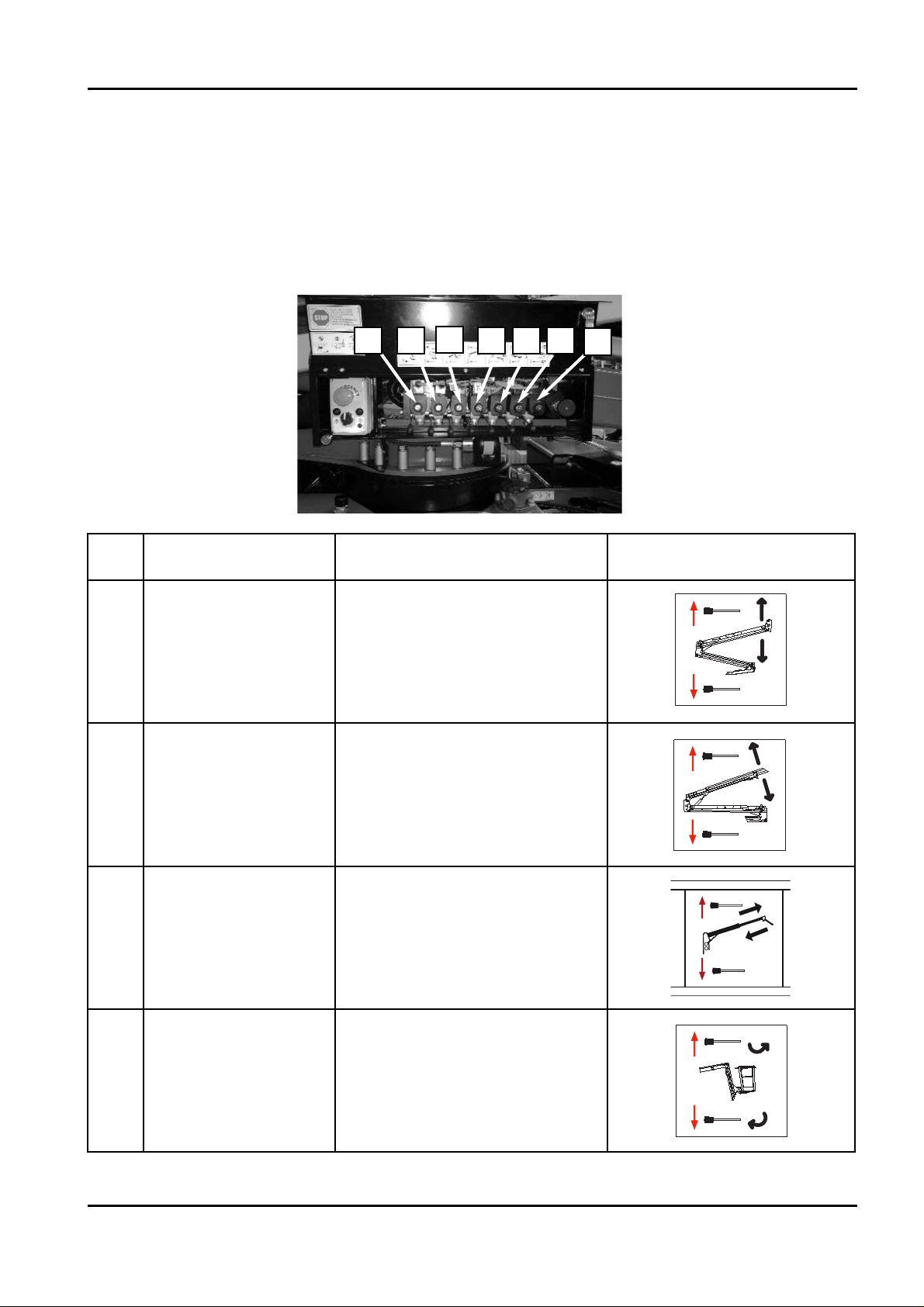
‑ AERIAL PART HYDRAULIC DISTRIBUTOR
The hydraulic distributor is fitted with levers and buttons for the selection of the required
movement, its direction and speed. The structure is moved by using the levers after holding
the key in position.
The meanings of the levers on the distributor are described below:
Ref. Description Lever/Movement obtained Pictogram near the control
6
First‑second arm
control
Moving lever 6 upwards:
1st‑2nd arm up
Moving lever 6 downwards:
1st‑2nd arm down
5
Third‑fourth
arm control
Moving lever 5 upwards:
3rd arm up
Moving lever 5 downwards:
3rd arm down
4
Extension arm control
Moving lever 4 upwards:
extension arm out
Moving lever 4 downwards:
extension arm in
3
Jib control
Moving lever 3 upwards:
jib opens
Moving lever 3 downwards:
jib folds
X20JPR0020413
BOOM LIFT MODELS X20JPLUS
JLG
63
1
2
3
4
5
6
7
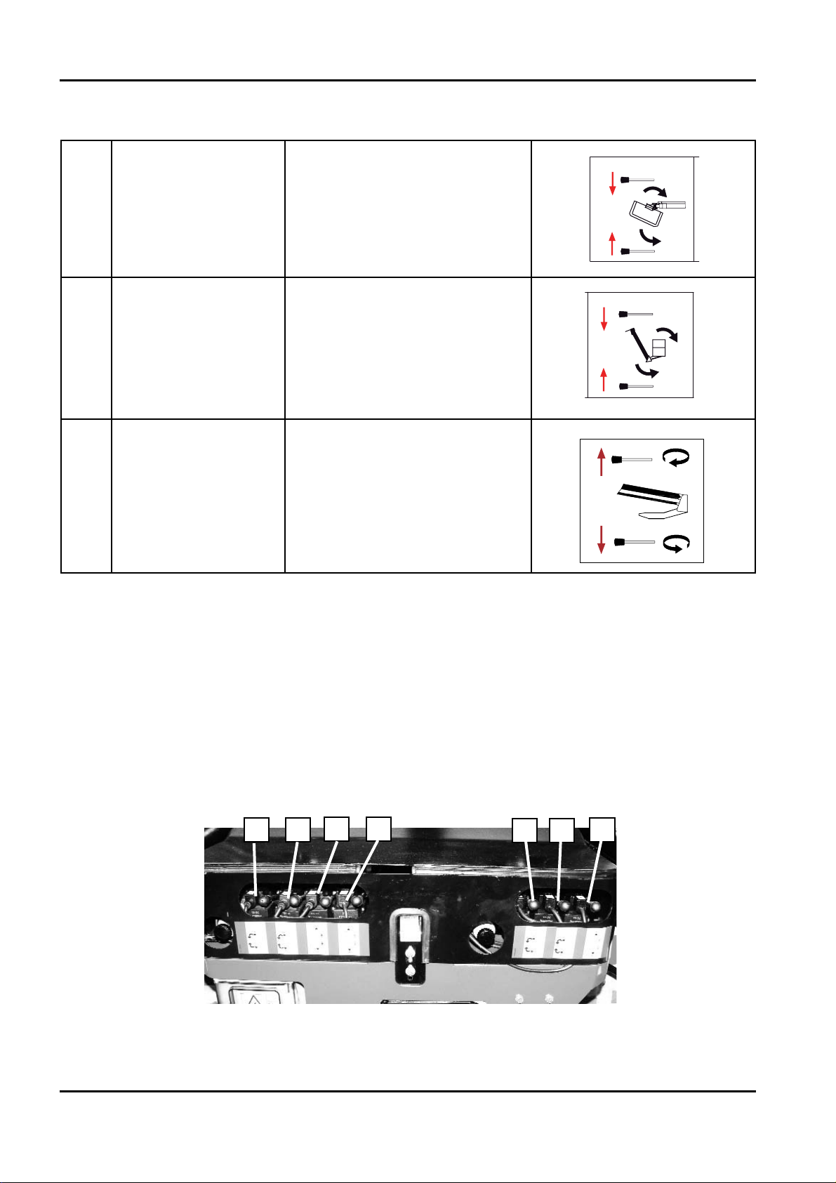
TRACKED UNDERCARRIAGE HYDRAULIC DISTRIBUTOR
X20JPR0020413
64
BOOM LIFT MODELS X20JPLUS
JLG
1
2
3 4
5
6
7
2
Basket rotation
control
Moving lever 2 downwards:
basket rotates clockwise
Moving lever 2 upwards:
basket rotates anticlockwise
1
Basket levelling
control
Moving lever 1 downwards:
basket opens
Moving lever 1 upwards:
basket closes
7
Rotation control
Moving lever 7 upwards:
clockwise rotation
Moving lever 7 downwards:
anticlockwise rotation
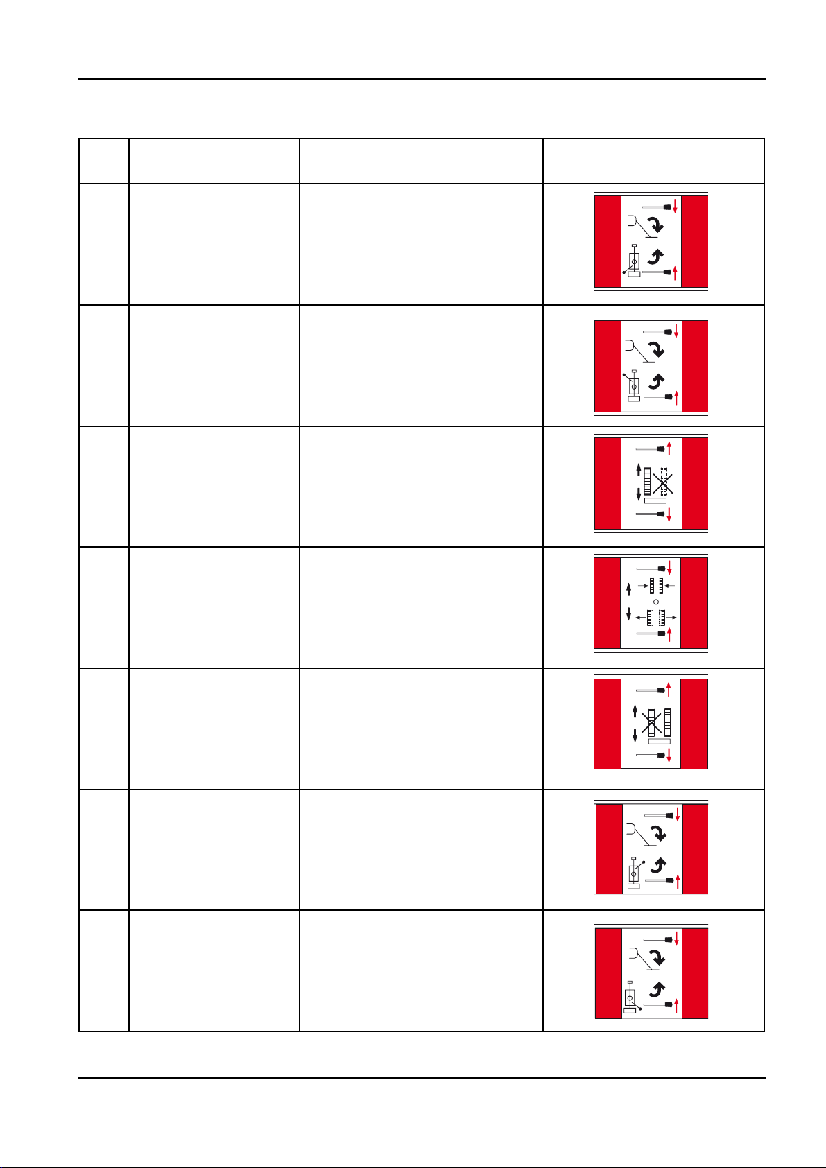
65
BOOM LIFT MODELS X20JPLUS
JLG
X20JPR0020413
Ref. Description Lever/Movement obtained Pictogram near the control
1
Rear left stabiliser
control
Moving lever 1 downwards:
rear L stabiliser down
Moving lever 1 upwards:
rear L stabiliser up
2
Front left stabiliser
control
Moving lever 2 downwards:
front L stabiliser down
Moving lever 2 upwards:
front L stabiliser up
3
Left track control
Moving lever 3 upwards:
moves left track forward
Moving lever 3 downwards:
moves left track backward
4
Track extension
control
Moving lever 4 downwards:
extends track
Moving lever 4 upwards:
narrows track
5
Right track control
Moving lever 5 upwards:
moves right track forward
Moving lever 5 downwards:
moves right track backward
6
Front right stabiliser
control
Moving lever 6 downwards:
front R stabiliser down
Moving lever 6 upwards:
front R stabiliser up
7
Rear right stabiliser
control
Moving lever 7 downwards:
rear R stabiliser down
Moving lever 7 upwards:
rear R stabiliser up
1608710001C
1608710002C

6. USING THE MACHINE
6.1 SAFETY STANDARDS TO ADOPT BEFORE USING THE PLATFORM
6.1.1 RISK OF ELECTROCUTION
If the machine must be used near electric power lines, the user must remain at a suitable
distance from the latter. The table below supplies the values relating to the minimum distan‑
ce from electric power lines depending on the type of voltage.
Keep a safe distance from mains power lines and electrical systems, considering the
possible range of movement of the platform and its oscillation, as well as the possi‑
ble oscillation of the power lines.
Before starting operation, examine the work area, taking note of overhead power
lines, moving machinery, such as overhead cranes and road, rail and building
equipment.
BOOM LIFT MODELS X20JPLUS
JLG
66
X20JPR0020413
SAFETY DISTANCE FROM POWER LINES
LINE RATED VOLTAGE SAFETY DISTANCE (METRES)
FROM TO
0 V 300 V 5
300 V 50 KV 5
50 KV 200 KV 5
200 KV 350 KV 6,1
350 KV 500 KV 7,6
500 KV 750 KV 10,7
750 KV 1000 KV 13,7
6.1.2 DANGER DUE TO ATMOSPHERIC CONDITIONS
DO NOT WORK IN UNFAVOURABLE ATMOSPHERIC CONDITIONS
Do not work in the presence of storms, snow, fog or wind exceeding 12 m/s.
Do not operate the machine when the ambient temperature drops below–10°C or exceeds
+40°C. Do not recharge the machine when the temperature is below 0°C or above 40°C.
Should it unexpectedly rain, before resuming work always remember to check correct stabili‑
sation of the platform and make sure that the ground is solid. Make sure that water has not
penetrated into the electrical contacts.
6.1.3 DANGER DUE TO THE WORK AREA
THE MACHINE CAN ONLY WORK ON COMPACT AND LEVEL GROUND.
Always verify that the slope of the ground in the platform positioning area does not exceed
the stabilization max inclination. During the stabilisation phase, use the spirit level positio‑
ned in proximity to the main controls to check that the maximum inclination of the coupling
with respect to horizontal does not exceed 1°.
Check the route for the presence of persons, holes, overhangs, obstacles, debris and cove‑
rings which may hide holes.
Before entering any high risk areas (refineries, power stations etc.) check accessibility with
plant safety staff.
X20JPR0020413
BOOM LIFT MODELS X20JPLUS
JLG
67
WARNING
IMPORTANTE

6.2 PROCEDURES FOR CORRECT USE
Below find the procedures for use of the platform as declared by the Constructor. Any use
different to that stated below, unless authorised in writing by the Constructor. is prohibited.
6.2.1 SUMMARY TABLE OF OPERATOR SAFETY STANDARDS
The summary table shown below lists the general safety standards that must be followed
scrupulously by the operator before using the platform.
Remember that a sticker with this table can be found near the controls positioned on the
basket, where it is well visible from the control position.
• The elevating platform can only be used by specialised, previously‑trained personnel.
• All operations of the extensible structures must be performed from the control position in
the basket. The travel and stabilisation operations must be carried out after checking that
there is complete visibility of the work area. Before starting operation, examine the work
area, taking note of overhead power lines, moving machinery, such as overhead cranes and
road, rail and building equipment.
• The instructions contained in the USER AND OPERATION MANUAL that is provided
together with the machine must be followed scrupulously.
• Do not exceed the maximum allowed capacity indicated in the USER AND OPERATION
MANUAL and on the basket.
• The operator must wear a hard hat and a safety harness appropriately attached to the rele‑
vant anchorage points on the basket.
Remember that the safety harnesses must be checked periodically.
The use of harnesses is compulsory in accordance with local legislation in each individual
country. In countries where the law does not require the use of such safety systems, the
employer and/or user is responsible for choosing the system to be used.
• Before starting work, the operator must make sure that all the safety devices are in good
working order, and check the efficiency of the main mechanical parts as well as the fuel and
hydraulic oil level.
Never operate on soft, rough, slimy ground or on slopes that exceed the allowable gradient,
in order to ensure that the platform is completely stable.
Make sure that the stabilisers rest on stable HORIZONTAL surfaces.
• Level the machine’s chassis perfectly respecting the maximum allowable gradient indicated
in the USER AND OPERATION MANUAL and visible on the spirit level.
• Before performing any movement, check that there are no obstacles in the work area and
that no people are in the trajectory.
• It is prohibited to carry out work at a distance of less than 5 metres from power lines and
electrical equipment.
• It is prohibited to operate in unfavourable atmospheric conditions.
• It is prohibited to anchor cables, ropes or the like to the platform and to use the platform as a
lifting device.
X20JPR0020413
68
BOOM LIFT MODELS X20JPLUS
JLG

• It is prohibited to secure ladders, stools or the like to the platform basket to increase the
working height.
• Always operate the controls slowly and smoothly, without reversing movements suddenly.
• Remember that the basket must only be loaded and unloaded FROM THE GROUND.
• Do not use the machine at temperatures below ‑20°C and above 40°C. Do not recharge
the batteries at temperatures below 0°C and above 40°C.
X20JPR0020413
BOOM LIFT MODELS X20JPLUS
JLG
69

6.3 WORK AREA
X20JPR0020413
70
BOOM LIFT MODELS X20JPLUS
JLG
MAXIMUM
CAPACITY 230 Kg
(2 persons 80x2=160kg
+
tool box 70 kg)

6.4 USE OF THE ELEVATING WORK PLATFORM (MEWP)
In the explanations contained in the following paragraphs, it is assumed that the operator
has already read and understood the contents of the previous sections of this manual. The‑
refore, warnings and photos which are already provided in other sections of this document
will be repeated only when absolutely necessary.
The JLG elevating work platforms are suitable for overhead jobs that are performed by an
operator from inside the basket. The platform must be used exclusively by skilled personnel
who are aware of the position and functions of all controls, instruments, indicators, warning
lights and the meaning of the stickers and indications on the machine.
The operator must have understood the platform operating procedures before using it.
Correct use of the platform requires, as well as the presence of the operator (or operators) in
the basket, also the presence of an expert operator on the ground who has to supervise work
and be ready to intervene in case of dangerous situations and for any emergency operations.
This implies that the personnel on the ground must be suitably trained regarding the func‑
tions of the controls and the procedures for use and that they have read the manual.
‑ Failure to comply with even one safety provision may cause injury/damage to the opera‑
tors and/or the machine.
‑ Keep a first aid box and a fire extinguisher near the work area. These must be used in
compliance with the regulations in force.
‑ Do not remain within the platform operating range. The area below must be cordoned
off; it is prohibited to throw objects from or towards the basket.
‑ Wear tight clothing and use all the PPE considered necessary based on the risk analysis
of each individual site (shoes, hard hats, gloves and safety belts).
‑ When the work needs to be performed by two or more persons, before starting always
agree on the correct procedure to follow. Always inform your fellow workers before star‑
ting the procedure.
‑ At low temperatures start the motor and let it run for a few minutes, so that the
hydraulic oil circulates and reaches at least 20°C before operating the platform.
‑ When climbing into the basket, fasten the safety harnesses immediately to the appro‑
priate fixing points before carrying out any operations. Remember that the safety har‑
X20JPR0020413
BOOM LIFT MODELS X20JPLUS
JLG
71
WARNING
WARNING
IMPORTANTE
IMPORTANTE

nesses must be checked and TESTED PERIODICALLY.
‑ If the pressure of the stabilisers on the ground exceeds the allowable pressure on the
ground, the support surface must be increased by inserting appropriate plates or a sub‑
strate of stable material (e.g. wood) between the ground and the stabiliser plate.
This material must ensure good friction with the underlying ground and with the stabili‑
ser plate. Any risk of the machine sliding on the ground must be eliminated.
6.4.1 PRELIMINARY CHECKS BEFORE STARTING WORK
Carry out the following checks every day before using the machine:
‑ Check that there are no leaks from the hydraulic system. If leaks are present, carry out the
necessary repairs and top up (see the paragraph on maintenance operations). Clean the area
using a solvent or a pressurised solution of water and detergent, taking care to prevent con‑
tact with the electrical parts.
‑ Make sure there is no corrosion and there are no cracks around welded points.
‑ Check the condition and correct tensioning of the track belts (see the paragraph on mainte‑
nance operations).
‑ Check that there are no broken, damaged or missing components. Check the correct tight‑
ness of the pin locking bolts and nuts or the safety locknuts. Before using the machine
replace, tighten and adjust them according to the instructions of the platform manufacturer.
‑ Eliminate debris that may cause fire or breakage, paying particular attention to the machine
control area and the area around the diesel/petrol engine.
‑ Clean the handrails, footboards and control levers removing any oil residues and debris
that may affect safety during the operations, thus putting the operator at risk. Check the
condition of the indicators and electric controls on the control board positioned on the
basket.
‑ Check the condition of the adhesive labels positioned on the machine to ensure they are
easily visible.
‑ Check that the quantity of fuel in the fuel tank is sufficient, in order to avoid useless down
time and emergency descents.
‑ Check the correct operation of all safety devices.
X20JPR0020413
72
BOOM LIFT MODELS X20JPLUS
JLG

6.4.2 STARTING THE PETROL/DIESEL ENGINE
Before starting the engine it is necessary to:
‑ Become familiar with all the procedures described in the USER AND OPERATION
MANUAL of the machine and of the engine, and to know the meaning of the safety
labels;
‑ Examine the safety rule summary table in the manual and follow all the instructions
given therein;
‑ Make sure that the fuel cap is properly tightened;
‑ Make sure that there are no residues of petrol or flammable materials near the exhaust
silencer or other areas subject to overheating;
‑ Make sure that no one is standing near the machine;
‑ Make sure that all the emergency STOP buttons are released; this condition can be
checked on the remote control display, where no icon should appear in position 7.
If the operator attempts to start the machine with the emergency stop button still pres‑
sed, an error message will appear on the display when the start button is pressed.
‑ The engine can be started from the ground using the start key, or directly by means of
the remote control. In this case it is necessary to move the engine start key to position
ON before getting on the basket. Use the ladder and the handrails to reach the control
position. At this point, press the button on the remote control to start the engine.
‑ The petrol engine starter is automatic.
‑ If the operator attempts to start one of the two motors while the other is already run‑
ning, starting will be impossible and the icon showing the motor already on will appear
at the centre of the screen.
For diesel engines it is possible to operate the preheating from the key or remote control.
The machines with petrol engines are equipped with an automatic preheating system,
pushing button 10 on remote control the running system is automatically set at 2200 rpm in
order to preheat the engine and improve the starting phases of use.
X20JPR0020413
BOOM LIFT MODELS X20JPLUS
JLG
73

If with this function active a movement that needs a different rotation system is attempted,
the machine will automatically exit from the preheating mode and will perform the move‑
ment at the necessary speed. See paragraph concerning the functions of the remote control
before using this option.
THE ENGINE MUST BE STARTED WITH ALL THE CONTROL BUTTONS AND JOY‑
STICKS IN NEUTRAL POSITION.
Always make sure there are no foreign objects (e.g. branches) that may accidentally operate
a control, as the platform may move suddenly out of the operator’s control and cause serious
harm to things and/or people.
Make sure that all the manual controls for the proportional valves are at rest.
6.4.3 STARTING THE ELECTRIC MOTOR
‑ Before starting the motor, be clearly aware of all the procedures described in the USER
AND OPERATION MANUAL and get familiar with the meaning of the safety stickers.
‑ Examine the safety rule summary table in the manual
and follow all the instructions given therein.
‑ Power the machine with an electric cable through the
connection positioned at the bottom near the electric
motor.
Close the switch located in the electrical panel near the
motor (see photo).
Before connecting the machine to the main power supply:
a) Make sure that the specifications of the power line correspond to the voltage and fre‑
quency indicated on the electric motor rating plate.
b) Check the condition of the power cable; it must be sized for a rated power of 2.2 kW. For
connection use a 3x2.5 mm2 three‑wire cable with F47 ground clamp, double insulation
and 16A plug. The maximum cable length must be 10 m.
c) Place an earth plate in the ground and connect it to the machine’s ground clamp or, if
this is not possible, make sure the power connection is earthed (e.g. indoors).
X20JPR0020413
74
BOOM LIFT MODELS X20JPLUS
JLG

‑ Make sure that all the emergency STOP buttons are released; this condition can be
checked on the remote control display, where no icon should appear in position 7.
If the operator attempts to start the machine with the emergency stop button still pres‑
sed, an error message will appear on the display when the start button is pressed.
‑ If the operator attempts to start one of the two motors while the other is already run‑
ning, starting will be impossible and the icon showing the motor already on will appear
at the centre of the screen.
‑ Use the button on the remote control to start the motor.
THE ENGINE MUST BE STARTED WITH ALL THE CONTROL BUTTONS AND JOY‑
STICKS IN NEUTRAL POSITION.
Always make sure that there are no foreign objects (for example, branches) that may acciden‑
tally operate a control, since the platform may move abruptly, independently of the opera‑
tor’s will, and cause serious injury or damage.
Make sure that all the manual controls for the proportional valves are at rest.
X20JPR0020413
BOOM LIFT MODELS X20JPLUS
JLG
75
6.4.4 STOPPING THE ENGINE/MOTOR
To stop the engine, press again button 11 on the remote control; it allows the engine to be
switched off or on depending on its status.
To stop the electric motor, press button 12; it allows the electric motor to be switched off or
on depending on its status.
6.4.5 STOPPING THE MOTOR LITHIUM VERSION
To switch off the electric motor, release the button or the lever on the remote control or relea‑
se the emergency control key.
The motor will stop automatically in 3‑4 seconds.
The electric motor can only be considered stopped if one of the emergency stop buttons
on the machine is pressed.
Whenever a movement of the machine has been completed and work needs to continue
with the machine off, one of the emergency stop buttons must be pressed and left activa‑
ted.
The machine must not be left off with the electronic board and the remote control powe‑
red.
X20JPR0020413
76
BOOM LIFT MODELS X20JPLUS
JLG

6.4.6 TRAVEL
The JLG machine is a self‑propelled machine able to easily move on any type of ground, over
steep slopes (up to 15°) and, considering the small dimensions, to enter narrow openings.
One condition for travel is that the four stabilisers are lifted from the ground and the machi‑
ne is in the transport or stabilisation configuration.
Travel can only be controlled from the position on the ground, always keeping a minimum
distance of 1 metre from the machine during ALL control operations.
When controlling the machine, before travelling make sure that the control position guaran‑
tees a perfect view of the entire machine and EVERY obstacle that may be in the machine’s
trajectory.
If a very precise control of travel movements is required, the motor speed can be reduced by
means of the speed selector button on the remote control.
Pay attention to the overall dimensions of the machine, especially if the stabilisers are not
turned to the transport position.
It is prohibited to get on or off the basket if this is not completely lowered.
The machine is not type‑approved for road circulation. The work and autonomous
shifting areas must be appropriately delimited and with signs according to the laws
in force regarding this subject. The machine must be loaded onto type‑approved
machines for any movement on public roads.
‑ During control operations, always keep a minimum distance of 1 metre from the machi‑
ne.
‑ It is recommended to travel on flat surfaces with the stabilisers completely lifted and set
in the transport position, so as to reduce the overall dimensions of the machine.
Travel is only allowed with carriage extended to the maximum width whenever possible
in the place of travel. This makes steering easier and increases machine stability.
‑ The 2nd travel speed can only be used for travelling in a straight line on solid and
level ground.
X20JPR0020413
BOOM LIFT MODELS X20JPLUS
JLG
77
DANGER
DANGER
ATTENZIONE
ATTENZIONE

TRAVEL PROCEDURE
Before travelling, proceed as follows:
‑ Check that all instructions previously given in this chapter have been complied with;
‑ Make sure that the ground is compact and can support the weight of the machine;
‑ Check that there are no obstacles in the travel area, considering the overall dimensions
of the machine;
‑ The machine is completely closed and aligned, in the transport or stabilisation position
or with the jib arm partially or totally lifted in the transport or stabilisation position.
This configuration is ONLY ALLOWED WHEN STRICTLY NECESSARY.
‑ Select the travel speed according to the need and as described above, operating the rele‑
vant button and checking the selection on display;
‑ Operate joysticks 1 and 8 to move the tracks;
If the operator attempts to travel with one or more stabilisers on the ground, an error
message will appear on the display warning the user to raise the stabilisers in order to
allow the machine to travel.
T
RAVELLING ON SLOPES
The maximum slope for travel is shown in the
machine specifications at the beginning of this
manual.
When travelling on inclined surfaces, lower the
stabilisers on the downward side for further
safety in the event of sudden changes in slope.
X20JPR0020413
78
BOOM LIFT MODELS X20JPLUS
JLG

79
The machine is equipped with an automatic system of inclination sensing during transla‑
tion, the possible translation speeds are adjusted according to the weight in basket,
undercarriage closed or opened, position of JIB and inclination of the ground. In case of
approach to dangerous inclinations for machine’s stability, both lateral and longitudinal, a
beeper is activated and afterwards the translation is forbidden. The only allowed operation
to exit this condition is activate the consent to movement pressing button 8 on remote con‑
trol and bring the machine in safety condition reducing the inclination, it is absolutely for‑
bidden to increase the inclination of the machine as it could cause overturning with conse‑
quent danger for operator or people nearby the machine.
The safety systems introduced to limit the risks of the manoeuvre are a valid help to the ope‑
rator but unfortunately cannot eliminate dangers caused by improper or regardless use of
the machine.
It is operator’s responsibility to run the machine safely, checking the ground conditions, eva‑
luating the obstacles and dangers in the working area and following the rules of this manual
and indications on decals and display of the machine.
Do not use the second travel speed to drive on sloping or uneven ground and when not
driving in a straight line.
BOOM LIFT MODELS X20JPLUS
JLG
X20JPR0020413
WARNING
WARNING
WARNING
IMPORTANTE
IMPORTANTE
IMPORTANTE
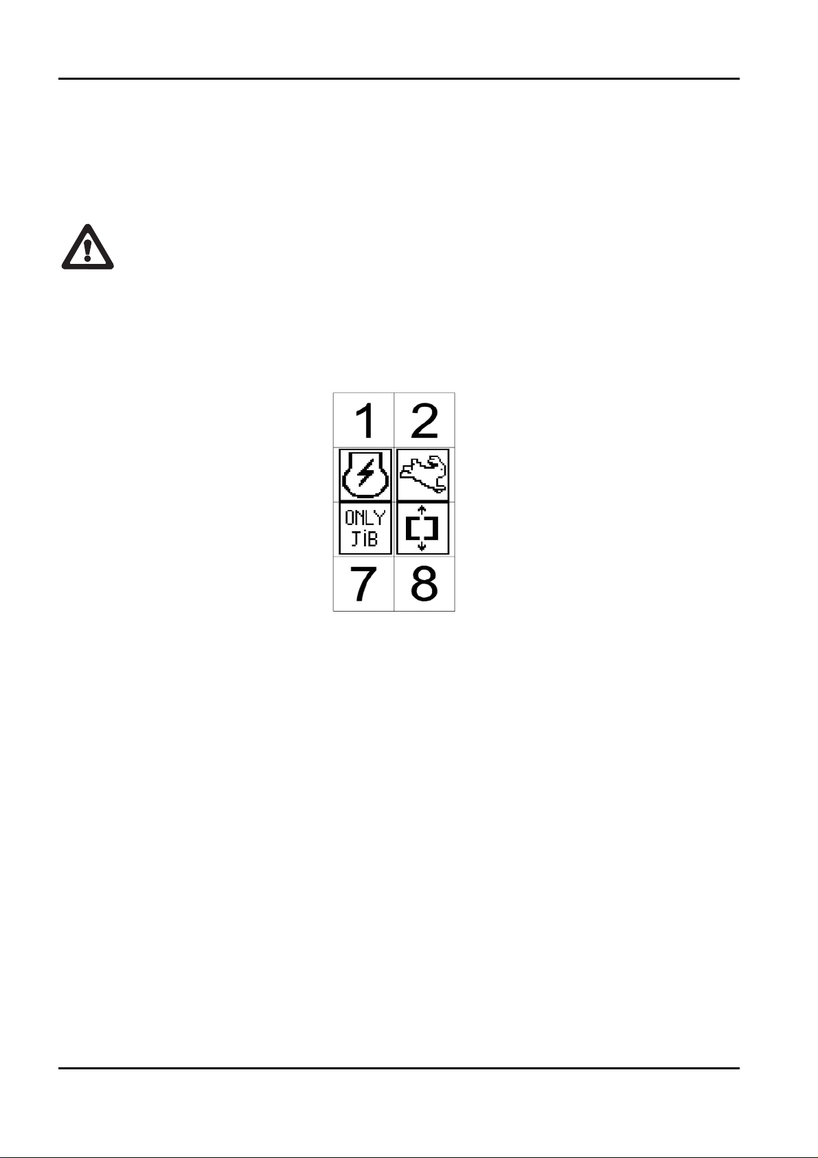
6.4.7 JIB ARM MOVEMENT FOR TRAVEL
To take on slopes from 10° to 15° in a longitudinal direction during travel, the jib arm can be
raised.
PERFORM THIS OPERATION ONLY WHEN REALLY NECESSARY. IN ALL OTHER
SITUATIONS, TRAVEL WITH THE MACHINE CLOSED AND ALIGNED.
Enabling of the jib is indicated by the icon in position 5 on the remote control.
The jib arm can be raised during travel only from the control position on the ground.
Before raising the jib arm for travel, check the following conditions:
‑ All the stabilisers must be lifted from the ground;
‑ No operators must be in the basket;
The control position on the ground must be used (the remote control must not be in
place in the basket);
‑ The aerial part safety device bypass key must not have been activated after the machine
has been closed and aligned.
If one or more of these conditions is not satisfied, the jib arm cannot be used and one of the
following error screens will be shown.
BOOM LIFT MODELS X20JPLUS
JLG
80
X20JPR0020413
DANGER
ATTENZIONE

After the conditions described above have been checked, make sure there are no obstacles in
the working area of the jib arm, and proceed as follows:
‑ Use joystick 6 to move the jib arm. If another joystick is used, an error message will be
shown on the display:
‑ AFTER PASSING THE INCLINE THAT REQUIRED THE JIB ARM TO BE OPENED,
RETURN THE MACHINE TO THE CLOSED CONFIGURATION TO CONTINUE
TRAVELLING.
‑ With the jib arm raised always travel at minimum speed and keep the jib arm as close to
the ground as possible.
‑ DO NOT travel downhill if the jib arm is not completely folded.
X20JPR0020413
BOOM LIFT MODELS X20JPLUS
JLG
81
6.4.8 PARKING THE MACHINE ON A SLOPE OR ON UNEVEN GROUND
When parking the machine on a slope or uneven ground with the stabilisers closed, make
sure that the carriage is in the open position and block the tracks using chocks to prevent the
machine from moving.
‑ Do not use the second travel speed to drive on sloping or uneven ground and when not
driving in a straight line.
6.4.9 STABILISING AND LEVELLING THE MACHINE
Once having decided where to park the machine, this can be stabilised and levelled. First of
all check that the surface can support the pressure exerted on the ground by the machine (see
the paragraph on technical specifications) and can contain the overall dimensions of the
machine with stabilisers lowered.
Stabilising the machine on a slope exceeding the allowed limits may cause instability and
consequently harm to or even death of operators or other persons in and around the
working area. Work must only be performed with the machine stabilised at an inclination
under the limits specified by the manufacturer.
‑ Always keep a distance from embankments or ditches that is equivalent to the depth of
such and observe the required safety distance from power lines.
‑ Avoid any contact with objects or persons when lowering the stabilisers.
STABILISATION PROCEDURE
Before moving the stabilisers make sure that:
‑ all instructions provided in this chapter have been complied with;
‑ the ground where the machine is stabilised is compact and can support the weight of the
machine and the maximum possible reaction force on one stabiliser;
NOTE: when working the load on one individual stabiliser can increase greatly due to
the shifting of weight, especially if extension and/or rotation operations are performed.
THIS MUST ALSO BE CONSIDERED WHEN EXAMINING THE GROUND.
‑ there are no obstacles on the stabilisation area and in the trajectory of each individual
stabiliser;
‑ the machine is completely closed and aligned, in the stabilisation position.
X20JPR0020413
82
BOOM LIFT MODELS X20JPLUS
JLG
DANGER
PERICOLO

The complete closure and alignment is displayed by the arrows on the machine (SEE
PHOTO) and the display of the icon in position 6 on the remote control.
‑ Stabilisation can be carried out from the control position in the basket or on the ground.
If performing the operation from the ground, make sure there is complete visibility of
the trajectory of each individual stabiliser before moving it and check that at the end of
the stabilisation procedure the distance between the ground and the lower limit of the
basket access ladder is less than 40 cm. If this is not the case, move the ladder to the
ground and carry out the stabilisation procedure from the basket.
‑ Select the motor speed as required and check the selection on the display.
Always perform stabilisation at slow speed.
‑ Press and hold the automatic stabilisation button 7 (see the corresponding paragraph).
If the movements are selected with the machine not completely closed and aligned, an
error message will be shown on the display.
X20JPR0020413
BOOM LIFT MODELS X20JPLUS
JLG
83

‑ Stabilisation will be completed when the machine is in horizontal position with toleran‑
ce of 1° and lifted at least 5 cm from the ground. Correct stabilisation will be confirmed
by the icon in position 5 on the display.
Always check the spirit level and make sure the slope is actually less than 1°.
MANUAL STABILISER CONTROL
The manual control of the stabilisers must not be used to stabilise the machine but only to
correct its inclination in the event of stabilisation in difficult conditions. It can also be used to
lower or lift the stabilisers individually in order to increase the stability of the machine, if it is
necessary to transit areas with obstacles or steep slopes.
Pressing the button once shows the screen for the manual operation of stabiliser 1, pressing it
a second time shows the screen for stabiliser 2 and so on until stabiliser 4. Pressing it once
again shows the initial display.
In the manual menu, pressing buttons 1 and 7 raises or lowers the selected stabiliser.
To verify the inclination of the chassis a spirit level is provided on the machine; when the air
bubble it contains is completely inside the green area (see photo below) the machine is in
X20JPR0020413
84
BOOM LIFT MODELS X20JPLUS
JLG
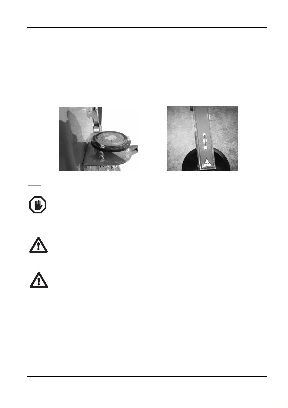
conditions that allow operation.
Please note that stabilize the machine on slopes greater than allowable limits (see technical
data of the machine) does not permit correct stabilization and is a serious danger for users.
On each stabiliser (see photo below), near the cylinder coupling, there is an orange light.
This light flashes to indicate that the stabiliser is resting on the ground.
Note
: IT IS IMPORTANT TO REMIND THAT WHEN THE STABILISERS ARE LOWE‑
RED THE CARRIAGE MUST ALWAYS BE RAISED FROM THE GROUND.
AFTER USING THE MANUAL STABILISER CONTROL, REMEMBER TO PRESSURISE
THE BOTTOM OF THE STABILISER CYLINDERS. TO DO THIS, RUN AN AUTO‑STA‑
BILISATION CYCLE OR LOWER EACH STABILISER FOR ONE SECOND.
An electronic spirit level on the electronic control board checks that the machine is effectively
level within the allowable tolerance and enables the movements of the aerial part.
Incorrect machine stabilisation does not ensure suitable stability to perform operations. The
Constructor prohibits the use of the machine if it is not stabilised as described in this manual;
the machine overturning may cause serious injury to or even death of its occupants and per‑
sonnel on the ground.
If one of the orange lights positioned on each stabiliser should flash even when the stabi‑
liser is lifted from the ground, stop the machine immediately and call the after‑sales servi‑
ce as this signals the breakage of the corresponding stabiliser microswitch.
X20JPR0020413
BOOM LIFT MODELS X20JPLUS
JLG
85
WARNING
IMPORTANTE

If working with the machine stabilised on slippery surfaces (marble, porphyry, polished
cement, smooth damp surfaces etc.) check that the movements of the basket do not cause the
tracks to move. If so, stop the operations and restore the safe operating conditions prescribed
by the manufacturer.
Make sure that the stabilisers rest on horizontal ground.
DO NOT REST THE STABILISERS ON VERTICAL OR INCLINED SURFACES.
6.4.10 AUTOMATIC LOWERING AND RAISING OF THE STABILISERS
JLG elevating platform is fitted with an innovative automatic levelling procedure that acts on
the stabilisers and uses the electronic spirit level provided on the main control board.
For the self‑levelling procedure, all the precautions described to this point apply.
Before starting the self‑stabilization make sure that the machine is on a slope less than the
total permitted limit for stabilization (see technical data of the machine) and verify that the
trajectory of the stabilizers is free of obstacles and impediments.
The automatic procedure for levelling the machine extends and retracts the stabilisers,
and consequently moves the machine. Always check that there are no people, animals or
things in the stabilisation area.
• AUTOMATIC LOWERING OF THE STABILISERS
Press and hold button 7 on the remote control.
The success of the self‑levelling procedure is confirmed by an icon displayed on the screen
for several seconds.
X20JPR0020413
86
BOOM LIFT MODELS X20JPLUS
JLG
DANGER
DANGER
ATTENZIONE
ATTENZIONE

If the selfstabilization procedure has not been completed and the OK message has not appea‑
red on the display it will not be possible to move the aerial part of the machine and at every
attempt to do it an error message will appear: AUTOSTAB NO. Repeat the Selfstabilization
operation to enable movements.
After the end of the procedure, always control that the spirit level is in the green zone. If this
does not occur contact JLG after sales service.
If during lowering one of the stabilisers does not touch the ground, the machine will conti‑
nue to operate the cylinder at the end of its stroke until the motor switches off or the self‑
levelling procedure ends. This situation is normal and indicates that the slope the machine is
situated on exceeds the allowable limit for stabilisation. If at the end of the stabilisation phase
the machine has to be lifted even further from the ground, a new self‑levelling procedure can
be run.
NOTE: using the self‑levelling procedure does not affect the operation of the stabilisers in
manual mode.
• AUTOMATIC RAISING OF THE STABILISERS
Press and hold button 1 on the remote control.
The four stabilisers will start to lower the machine and then will retract completely.
X20JPR0020413
BOOM LIFT MODELS X20JPLUS
JLG
87
OK

The end of the automatic stabiliser raising cycle is shown on a screen for a few seconds. If
this screen is not shown, the automatic stabiliser raising procedure can still be considered
completed once all the four stabilisers have been completely retracted and consequently the
relevant cylinders are at the end of their stroke.
If problems occur during either of these procedures, immediately release the selected but‑
ton to stop all the movements. Stabilising the machine on a slope exceeding the allowed
limits may cause instability and consequently harm to or even death of operators or other
persons in and around the working area. Work must only be performed with the machine
stabilised at an inclination under the limits specified by the manufacturer.
The elevating platform is considered stabilised when the slope is less than 1° and the tracks
are raised at least 5 cm from the ground. NEVER WORK AT A HEIGHT WITH THE
TRACKS NOT COMPLETELY RAISED FROM THE GROUND.
6.4.11 TRACK GAUGE EXTENSION
To adjust the track gauge, proceed as follows:
• Use buttons 3‑9 to extend/narrow the track gauge.
NOTE: the track gauge extension operations should be performed with the machine stabili‑
sed and lifted from the ground. If this is not possible, perform the extension operations with
the tracks moving.
Do not extend/narrow the track gauge when the tracks are stationary and resting on the
ground.
BOOM LIFT MODELS X20JPLUS
JLG
88
X20JPR0020413
WARNING
IMPORTANTE

89
BOOM LIFT MODELS X20JPLUS
JLG
X20JPR0020413
6.4.12 MOVING THE BASKET
Once the machine has been stabilised correctly (check the icon in pos. 5), the basket can be
moved.
• It is prohibited to load material of any type into the basket if the machine is not stabi‑
lised and completely closed. To load and unload the basket the icon in position 6 on
the remote control must be displayed. Loading material into the basket when it is lif‑
ted (e.g. from roofs, balconies etc.) causes the machine to overturn, exposing the occu‑
pants and personnel on the ground to potential risk of death.
• It is absolutely forbidden to use the machine to lift loads both in the basket and con‑
nected in other way to the structure; the machine can lift two persons (80 kg each)
plus 70 kg of tools.
• During machine lowering, near where the upper arms rest on the lower ones, a poten‑
tial shearing risk is created, appropriately signalled by stickers; it is the user’s respon‑
sibility to move any persons away from this area.
• Pay maximum attention to obstacles that may collide with the various parts of the
machine during movement. Before carrying out ANY movement, make sure that
nothing can interfere with ANY part of the machine (branches, protruding parts of
buildings, etc.).
It is prohibited to introduce objects into the basket that provide high resistance to wind
pressure (e.g. large signs) even if they are within the machine’s capacity limits.

PROCEDURE FOR ROUTINE MOVEMENT OF THE AERIAL PART
• Before moving the aerial part, make sure that:
‑ all instructions provided in this chapter have been complied with;
‑ there are no obstacles in the work area;
‑ all the conditions necessary for working at a height are met:
the machine is stabilised and levelled: icon 5 shown on the display,
the weight in the basket is below the maximum allowed,
the remote control is positioned in the basket.
‑ the basket access ladder has been folded into the raised position so as not to risk
contact during movement of the aerial part.
• The aerial part can ONLY be moved from the control position in the basket.
• Select the motor speed as required and check the selection on the display.
• Use joysticks 2, 3, 4, 5, 6, 7 to move the aerial part as described in the paragraph regar‑
ding the description of the controls.
• If the movements are selected when one of the conditions listed above is not satisfied, an
error message will be shown on the display indicating what conditions are OK and what
are not satisfied (FAIL). If the missing condition is stabilisation, the message will also
indicate what stabiliser is not resting on the ground.
ST1: if OK stabiliser 1 is resting on the ground
ST2: if OK stabiliser 2 is resting on the ground
ST3: if OK stabiliser 3 is resting on the ground
ST4: if OK stabiliser 4 is resting on the ground
INLC: if OK the machine is under the maximum inclination limit
LOAD: if OK, the load is less than the maximum working load
allowed
BASKET: if OK the remote control is in place in the basket
PEDAL: if OK the footswitch is pushed
X20JPR0020413
90
BOOM LIFT MODELS X20JPLUS
JLG
ERROR
ST1 NO
ST2 NO
ST3 NO
ST4 NO
INCL OK
LOAD OK
BASKET OK
PEDAL OK

OVERLOAD ALARM
If during the basket loading phases the max allowable load is exceeded based on the position
of the jib arm, all movements of the aerial part will be disabled and an error message will be
shown on the display, first on the entire screen and then in position 5.
The alarm will only be reset when the overload is removed. Normal machine operation can
be resumed only then.
B
ASKET LIFTING ALARM
If when using the machine at a height, for whatever reason, the basket is lifted from its posi‑
tion on the load sensor, an alarm prevents all movements of the machine and the display on
the remote control shows an error message.
The alarm is reset only when the basket is fitted back on the load sensor.
X20JPR0020413
BOOM LIFT MODELS X20JPLUS
JLG
91
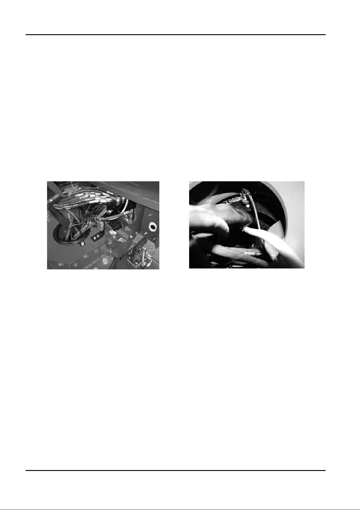
BOOM LIFT MODELS X20JPLUS
JLG
92
X20JPR0020413
ROTATION WITH 1ST‑2ND ARM FOLDED AND 1ST‑2ND ARM DESCENT ON THE
THERMIC/LITHIUM ENGINE
If the turret is rotated with the first or second arm folded or nearly folded, there is the risk of
the first arm hitting against the engine. For this reason, free rotation areas and limited rota‑
tion areas are defined.
LIMITED ROTATION AREA: is an area near the engine where this may be hit by the first
arm.
FREE ROTATION AREA: is the rest of the rotation area that does not coincide with the limi‑
ted rotation area.
These two areas are identified through the combined control of two sensors: a microswitch
that verifies the height of the first and second arm, and a proximity switch mounted inside
the turntable that senses the position of the turret while it turns.
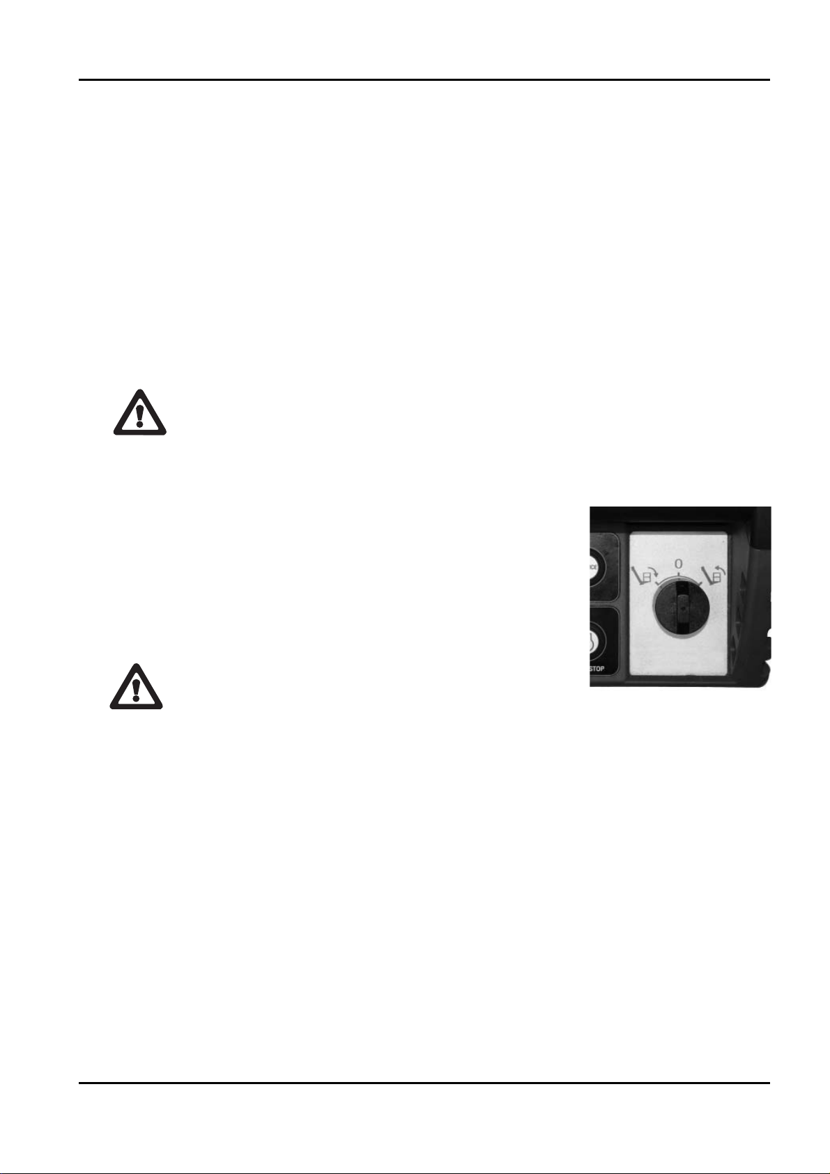
6.4.13 MANUAL LEVELLING OF THE BASKET
The JLG elevating work platform is provided with an automatic basket levelling device that
was designed so that the basket floor is always parallel to the ground independently of the
movements of the arms.
However, due to causes such as leaks and malfunctions, it may be necessary to operate
manually to bring the basket to the optimal position. Proceed as follows to make such adjust‑
ments:
‑ try to move the basket to the travel position by closing the extensible structure comple‑
tely (this, only if the problem occurred while the basket was in a raised position);
‑ only carry out this operation if the basket angle exceeds 10°. If this is not the case, carry
out manual levelling at the minimum possible height, within the limit of 10°. The mini‑
mum height is reached by completely closing the 1st and 2nd arm, extension arm, jib
arm and, as much as possible, the 3rd arm;
‑ Insert the key into the corresponding slot in the remote con‑
trol (see photo);
‑ Turn the key in the direction corresponding to the required
movement.
Basket levelling is subjected to some conditions:
‑ it is an exceptional manoeuvre to be performed only in case of slight malfunctions of the
self‑levelling procedure, therefore if the problem occurs frequently, have the basket
checked by an authorised workshop;
‑ the manual levelling control is allowed only from the basket, with the extensible structu‑
re completely closed and aligned, otherwise the operator may be seriously injured fol‑
lowing contact with moving parts of the machine;
‑ it is absolutely forbidden to use the levelling manoeuvre for purposes other than those
described herein (e.g. to lift objects, to increase the reach of the platform etc.), in order to
avoid serious and even fatal accidents.
X20JPR0020413
BOOM LIFT MODELS X20JPLUS
JLG
93
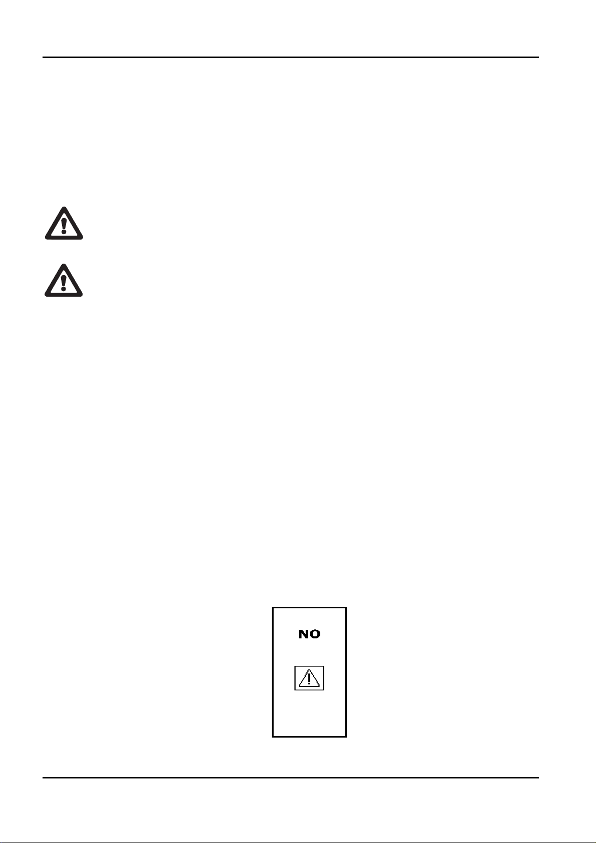
6.5 EMERGENCY OPERATIONS FOR THE AERIAL PART
The machine was designed considering possible emergency situations such as mechanical
and electrical breakdowns, sudden operator illness etc. In all of these cases the machine can
be operated both from the basket and from the ground so as to bring it back to the transport
configuration or however in such a way as to rescue the occupant/occupants from the basket.
These operations are described below.
Personnel must be present on the ground at all times during platform operation.
The operations described below must be performed in SEQUENCE, starting from the first
and then continuing with the following ones until the last only if the emergency opera‑
tion being performed has not been successful.
6.5.1 EMERGENCY DESCENT CONTROLLED FROM THE BASKET
The basket emergency descent procedure can be controlled from the basket itself only if the
electrical system of the machine is working; proceed as follows:
‑ hold button 4 on the remote control (paragraph 2.1.1 Control position);
‑ check the control through icon 8 on the display (paragraph 4.1.1.1 Display main screen);
‑ use the joystick corresponding to the arm being folded until reaching the required height
(paragraph 4.2.1 Joystick);
‑ release button 4.
As descent is due to gravity, the platform and basket cannot be rotated and the telescopic
arm cannot be extended or retracted, therefore the basket is lowered vertically at a distance
from the centre of rotation that depends on the configuration of the machine at the time
when the emergency situation occurred.
If a joystick corresponding to a movement without emergency descent is activated, an error
icon will be shown on the display:
The message disappears when the joystick is released.
X20JPR0020413
94
BOOM LIFT MODELS X20JPLUS
JLG
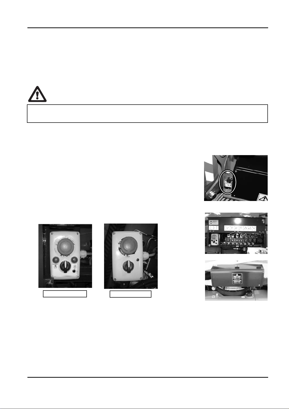
6.5.2 OPERATING THE MACHINE FROM THE EMERGENCY CONTROL POSITION
ON THE GROUND IF THE OPERATOR IS TAKEN ILL
This function is only used if the operator in the basket becomes suddenly ill and unable to
perform ordinary movements and the emergency descent of the basket.
For information on the controls in the emergency position, see the paragraph Emergency
position controls.
‑ Withdraw the opening key of the distributor’s controls pro‑
tection from the engine keys group in the electrical compo‑
nents box.
‑ Insert the key to open the distributor’s controls protection
and access the controls.
‑ Operate on the enabling selector in the control panel of the
emergency position, rotating it clockwise and keeping it in
position (in the Lithium version this starts the engine).
‑ Start the motor using the corresponding button in case of thermic version.
‑ Rotate the key selector clockwise and hold it in position (in Lithium version this starts
the motor).
‑ Make sure that the green indicator light on the emergency position control panel comes
on, i.e. that the conditions necessary to be able to move the aerial part are satisfied.
‑ Move the aerial part of the machine using the manual levers positioned on the distri‑
butor on the ground as described on the sticker placed near them and as specified in
this manual.
‑ Close the protection and put the keys back in their original position.
The sole purpose of the emergency descent from the ground is to operate in the event of
system breakdown and to bring the basket to the ground, all other uses are prohibited.
X20JPR0020413
BOOM LIFT MODELS X20JPLUS
JLG
95
THERMIC MOTOR
LITHIUM MOTOR

6.5.3 EMERGENCY DESCENT IN THE CASE WHERE THE STABILISERS ARE ACCI‑
DENTALLY RETRACTED
While it is recommended to follow the instructions provided in the paragraph on stabilising
the machine, for various reasons one of the stabilisers may lose contact with the ground,
thus changing the angle of the machine or causing a foot plate to lift from the ground. If this
occurs when the machine is at a height, movements are stopped and disabled immediately.
To restore operation of the platform (close the aerial part and then stabilise the machine
again) the electrical emergency descent function can be used, which involves only the return
of the aerial part.
If this is not possible due to the presence of objects that interfere with the operation, person‑
nel on the ground can allow the operator in the basket to close the machine.
The operators on the ground can bypass the machine’s safety devices and allow the operator
in the basket to close the machine or allow the manual operations as described in the pre‑
vious paragraphs, in order to bring the operator back to the ground.
Read the instructions provided below before performing the operation as it is
potentially dangerous for the operator in the basket.
Proceed as follows:
‑ Open the electrical components compartment.
‑ Position the emergency key on the electrical components compartment, removing it from
the side where this is lead‑sealed (see photo);
‑ Turn the emergency key anticlockwise and hold it in position (see sticker).
X20JPR0020413
96
BOOM LIFT MODELS X20JPLUS
JLG
 Loading...