


 Loading...
Illustrated Parts Manual
Models 600A 600AJ
Prior to
S/N 0300069000
P/N
3120841
September 1, 2013
REVISION LOG
NOTES:
ADE SYSTEM IDENTIFICATION
Most 600A and 600AJ machines from S/N 64249 incorporate the ADE System, but no clean S/N break exist. The following machine serial numbers prior to S/N 64249 also utilize ADE System: 63908, 63912, 63932, 63936, 63938, 63954, 63959 and 63963. A machine that incorporates ADE System can be outwardly identified by the analyzer connection at the base of the platform control box.
MANUAL REVISION LOG:
February 1996 - Original Issue Of Manual
September 1997 - Revised (Manual edited to 0010519 Revision 31)
February, 1998 - Change 1 (Manual edited to 0010519 Revision 37)
Pages Affected:
Cover
Effectivity Page: a
Table of Contents Pages: i & ii Section 1 Pages: 1-1 & 1-28 to 1-30
Section 2 Pages: 2-1, 2-2, 2-4 to 2-6, 2-10, 2-20, 2-22 to 2-24, 2-26, 2-27, 2-29, 2-31 to 2-36, 2-38, 2-39, 2-42, 2-45, 2-48, to 2-51, 2-58 to 2-59B, 2-62 to 2-65 & 2-67 to 2-69
Section 3 Pages: 3-1, 3-13, 3-21 to 3-24 Section 4 Pages: 4-1, 4-5 to 4-9, 4-17 & 4-18 Section 5 Pages: 5-1 & 5-28 to 5-30
Section 7 Pages: 7-1 to 7-28 Section 8 Pages: 8-4 & 8-5
3120841 |
A |
REVISION LOG
Section 9 Pages: 9-1 Section 10 Pages: 10-2
February 12, 1999 - Revised (Manual edited to 0010519 Revision 50) September 30, 1999 - Revised (Manual edited to 0010519 Revision 58) March 1, 2000 - Revised (Manual edited to 0010519 Revision 63) August 22, 2001 - Revised (Manual edited to 0010519 Revision 73)
(Manual edited to 0010577 Revision 6 With ADE System) March 1, 2002 - Revised (Manual edited to 0010577 Revision 9)
July 31, 2002 - Revised (Manual edited to 0010577 Revision 18)
February 15, 2003 - Added "Prior to S/N 0300069000" to Front Cover. Refer to Parts Manual 3121855 for Machines Built S/N 0300069000 to 0300087000.
March 6, 2003 - Revised Manual
June 16, 2003 - Revised Manual
May 5, 2004 - Revised Manual
April 11, 2005 - Revised Manual November 15, 2005 - Revised Manual April 18, 2006 - Revised Manual
July 19, 2006 - Revised Manual December 12, 2006 - Revised Manual May 1, 2007 - Revised Manual August 16, 2007 - Revised Manual December 4, 2007 - Revised Manual
March 31, 2008 - Revised Manual
September 15, 2008 - Revised Manual
February 15, 2009 - Revised Manual
August 1, 2009 - Revised Manual
March 25, 2010 - Revised Manual
August 15, 2010 - Revised Manual
May 27, 2011 - Revised Manual
August 29, 2011 - Revised Manual
December 23, 2011 - Revised Manual
April 27, 2012 - Revised Manual
July 24, 2012 - Revised Manual
November 2, 2012 - Revised Manual
March 7, 2013 - Revised Manual
June 6, 2013 - Revised Manual
September 1, 2013 - Revised Manual
B |
3120841 |
TABLE OF CONTENTS
FIGURE NO. |
TITLE |
PAGE NO. |
SECTION 1 - FRAME . . . . . . . . . . |
. . . . . . . . . . . . . . . . . . . . . . . . . . . . . . . . . . . . . . . . . |
. . .1-1 |
1-1 2WD FRONT AXLE AND STEERING INSTALLATIONS . . . . . . . . . . . . . . . . . . . . . . . . .1-2 1-2 4WD FRONT AXLE AND STEERING INSTALLATIONS . . . . . . . . . . . . . . . . . . . . . . . . .1-6 1-3 4WS REAR STEERING INSTALLATIONS . . . . . . . . . . . . . . . . . . . . . . . . . . . . . . . . . . . .1-10 1-4 TIRE AND WHEEL DRIVE INSTALLATIONS . . . . . . . . . . . . . . . . . . . . . . . . . . . . . . . . . .1-12 1-5 DRIVE HUB ASSEMBLY . . . . . . . . . . . . . . . . . . . . . . . . . . . . . . . . . . . . . . . . . . . . . . . . .1-16 1-6 DRIVE BRAKE ASSEMBLY . . . . . . . . . . . . . . . . . . . . . . . . . . . . . . . . . . . . . . . . . . . . . . .1-18 1-7 DRIVE MOTOR ASSEMBLY - SUNSTRAND (2WD) . . . . . . . . . . . . . . . . . . . . . . . . . . . .1-22 1-8 DRIVE MOTOR ASSEMBLY - REXROTH (4WD) . . . . . . . . . . . . . . . . . . . . . . . . . . . . . . .1-24 1-9 TOW PACKAGE INSTALLATION (OPTIONAL) . . . . . . . . . . . . . . . . . . . . . . . . . . . . . . . .1-26
SECTION 2 - TURNTABLE . . . . . . . . . . . . . . . . . . . . . . . . . . . . . . . . . . . . . . . . . . . . . . . . .2-1
2-1 CONTROL VALVES INSTALLATIONS . . . . . . . . . . . . . . . . . . . . . . . . . . . . . . . . . . . . . .2-2 2-2 MAIN VALVE BLOCK ASSEMBLY . . . . . . . . . . . . . . . . . . . . . . . . . . . . . . . . . . . . . . . . . .2-6 2-3 ACCESSORY VALVE ASSEMBLIES . . . . . . . . . . . . . . . . . . . . . . . . . . . . . . . . . . . . . . . .2-10 2-4 SWING DRIVE, TURNTABLE BEARING & LOCK INSTALLATIONS . . . . . . . . . . . . . . . .2-12 2-5 SWING HUB ASSEMBLY . . . . . . . . . . . . . . . . . . . . . . . . . . . . . . . . . . . . . . . . . . . . . . . .2-14 2-6 SWING BRAKE ASSEMBLY . . . . . . . . . . . . . . . . . . . . . . . . . . . . . . . . . . . . . . . . . . . . . .2-16 2-7 SWING MOTOR ASSEMBLY . . . . . . . . . . . . . . . . . . . . . . . . . . . . . . . . . . . . . . . . . . . . .2-20 2-8 DEUTZ ENGINE INSTALLATION - WITHOUT NOISE REDUCTION (PRIOR TO
S/N 0300029930) . . . . . . . . . . . . . . . . . . . . . . . . . . . . . . . . . . . . . . . . . . . . . . . . . . .2-22 2-9 DEUTZ ENGINE INSTALLATION - WITH NOISE REDUCTION (S/N 0300028190
TO S/N 0300069000) . . . . . . . . . . . . . . . . . . . . . . . . . . . . . . . . . . . . . . . . . . . . . . . . .2-28 2-10 GENERATOR INSTALLATION (OPTIONAL - DEUTZ ENGINE MACHINES) . . . . . . . . .2-36 2-11 PISTON PUMP ASSEMBLY. . . . . . . . . . . . . . . . . . . . . . . . . . . . . . . . . . . . . . . . . . . . . . .2-40 2-12 GEAR PUMP ASSEMBLY . . . . . . . . . . . . . . . . . . . . . . . . . . . . . . . . . . . . . . . . . . . . . . . .2-46 2-13 TANKS INSTALLATION . . . . . . . . . . . . . . . . . . . . . . . . . . . . . . . . . . . . . . . . . . . . . . . . . .2-48 2-14 ROTARY COUPLING INSTALLATION . . . . . . . . . . . . . . . . . . . . . . . . . . . . . . . . . . . . . . .2-50 2-15 GROUND CONTROL BOX INSTALLATIONS (PRIOR TO S/N 0300064249) . . . . . . . . .2-52 2-16 GROUND CONTROL BOX INSTALLATIONS (ADE SYSTEM) (S/N 0300064249
TO S/N 0300069000) . . . . . . . . . . . . . . . . . . . . . . . . . . . . . . . . . . . . . . . . . . . . . . . . .2-56 2-17 ELECTRICAL OPTIONS INSTALLATION (TURNTABLE MOUNTED) . . . . . . . . . . . . . . .2-60 2-18 ENGINE TRAY JACK INSTALLATION (OPTIONAL) . . . . . . . . . . . . . . . . . . . . . . . . . . . .2-64 2-19 HOODS INSTALLATIONS - WITHOUT NOISE REDUCTION . . . . . . . . . . . . . . . . . . . . .2-66 2-20 HOODS INSTALLATIONS - WITH NOISE REDUCTION . . . . . . . . . . . . . . . . . . . . . . . . .2-70
SECTION 3 - BOOM . . . . . . . . . . . . . . . . . . . . . . . . . . . . . . . . . . . . . . . . . . . . . . . . . . . . . . .3-1
3-1 BOOMS AND CYLINDERS INSTALLATION - 600A . . . . . . . . . . . . . . . . . . . . . . . . . . . . .3-2 3-2 BOOMS AND CYLINDERS INSTALLATION - 600AJ . . . . . . . . . . . . . . . . . . . . . . . . . . . .3-6 3-3 TOWER BOOM ASSEMBLIES . . . . . . . . . . . . . . . . . . . . . . . . . . . . . . . . . . . . . . . . . . . .3-12 3-4 MAIN BOOM ASSEMBLIES . . . . . . . . . . . . . . . . . . . . . . . . . . . . . . . . . . . . . . . . . . . . . . .3-16 3-5 ROTATOR ASSEMBLIES (FRONT ENTRY PLATFORM) . . . . . . . . . . . . . . . . . . . . . . . .3-20 3-6 ROTATOR ASSEMBLIES (SIDE ENTRY PLATFORM) . . . . . . . . . . . . . . . . . . . . . . . . . .3-24 3-7 VALVES AND SWITCHES INSTALLATION (BOOM MOUNTED) . . . . . . . . . . . . . . . . . .3-26 3-8 BOOM WIPERS INSTALLATIONS (OPTIONAL) . . . . . . . . . . . . . . . . . . . . . . . . . . . . . . .3-30
SECTION 4 - PLATFORM. . . . . . . . . . . . . . . . . . . . . . . . . . . . . . . . . . . . . . . . . . . . . . . . . . .4-1
4-1 PLATFORM COMPONENTS INSTALLATION (FRONT ENTRY) . . . . . . . . . . . . . . . . . . .4-2 4-2 PLATFORM COMPONENTS INSTALLATION (SIDE ENTRY) . . . . . . . . . . . . . . . . . . . . .4-6 4-3 PLATFORM CONSOLE ASSEMBLY (PRIOR TO S/N 0300064249) . . . . . . . . . . . . . . . .4-10
3120841 |
i |
TABLE OF CONTENTS
FIGURE NO. |
TITLE |
PAGE NO. |
4-4 PLATFORM CONSOLE ASSEMBLY (WITH ADE SYSTEM) (S/N 0300064249 TO
S/N 0300069000). . . . . . . . . . . . . . . . . . . . . . . . . . . . . . . . . . . . . . . . . . . . . . . . . . . . 4-16 4-5 OEM CONTROLLER ASSEMBLY (SWING AND LIFT) (PRIOR TO S/N 0300039749) . . 4-20 4-6 OEM CONTROLLER ASSEMBLY (SWING AND LIFT) (S/N 0300039749 TO
S/N 0300064249). . . . . . . . . . . . . . . . . . . . . . . . . . . . . . . . . . . . . . . . . . . . . . . . . . . . 4-24 4-7 OEM CONTROLLER ASSEMBLY (SWING AND LIFT) (WITH ADE SYSTEM)
(S/N 0300064249 TO S/N 0300069000) . . . . . . . . . . . . . . . . . . . . . . . . . . . . . . . . . . 4-26 4-8 OEM CONTROLLER ASSEMBLY (DRIVE/STEER) (PRIOR TO S/N 0300039749) . . . . . 4-30 4-9 OEM CONTROLLER ASSEMBLY (DRIVE/STEER) (S/N 0300039749 TO
S/N 0300064249). . . . . . . . . . . . . . . . . . . . . . . . . . . . . . . . . . . . . . . . . . . . . . . . . . . . 4-34 4-10 OEM CONTROLLER ASSEMBLY (DRIVE/STEER) (WITH ADE SYSTEM)
(S/N 0300064249 TO S/N 0300069000) . . . . . . . . . . . . . . . . . . . . . . . . . . . . . . . . . . 4-36 4-11 SOFT TOUCH SYSTEM INSTALLATION (OPTIONAL) . . . . . . . . . . . . . . . . . . . . . . . . . . 4-40 4-12 LOAD SENSING SYSTEM INSTALLATION (FRONT ENTRY PLATFORM) . . . . . . . . . . 4-44
SECTION 5 - CYLINDER . . . . . . . . . . . . . . . . . . . . . . . . . . . . . . . . . . . . . . . . . . . . . . . . . . . 5-1
5-1 AXLE LOCKOUT CYLINDER ASSEMBLY . . . . . . . . . . . . . . . . . . . . . . . . . . . . . . . . . . . . 5-2 5-2 PLATFORM LEVEL CYLINDER ASSEMBLIES (PRIOR TO S/N 0300024714) . . . . . . . . 5-4 5-3 PLATFORM LEVEL CYLINDER ASSEMBLIES (S/N 0300024714 TO
S/N 0300069000) . . . . . . . . . . . . . . . . . . . . . . . . . . . . . . . . . . . . . . . . . . . . . . . . . . . 5-8 5-4 LEVEL (UPRIGHT) CYLINDER ASSEMBLY . . . . . . . . . . . . . . . . . . . . . . . . . . . . . . . . . . 5-12 5-5 LIFT (ARTICULATING JIB) CYLINDER ASSEMBLY . . . . . . . . . . . . . . . . . . . . . . . . . . . . 5-14 5-6 LIFT (MAIN BOOM) CYLINDER ASSEMBLY . . . . . . . . . . . . . . . . . . . . . . . . . . . . . . . . . 5-16 5-7 LIFT (TOWER BOOM) CYLINDER ASSEMBLY . . . . . . . . . . . . . . . . . . . . . . . . . . . . . . . 5-18 5-8 MASTER CYLINDER ASSEMBLIES . . . . . . . . . . . . . . . . . . . . . . . . . . . . . . . . . . . . . . . . 5-20 5-9 STEER CYLINDER ASSEMBLIES . . . . . . . . . . . . . . . . . . . . . . . . . . . . . . . . . . . . . . . . . . 5-24 5-10 TELESCOPE (MAIN BOOM) CYLINDER ASSEMBLIES . . . . . . . . . . . . . . . . . . . . . . . . . 5-26 5-11 TELESCOPE (TOWER BOOM) CYLINDER ASSEMBLY . . . . . . . . . . . . . . . . . . . . . . . . . 5-28 5-12 CYLINDER BELLOWS INSTALLATION (OPTIONAL) . . . . . . . . . . . . . . . . . . . . . . . . . . . 5-30
SECTION 6 - HYDRAULIC. . . . . . . . . . . . . . . . . . . . . . . . . . . . . . . . . . . . . . . . . . . . . . . . . . 6-1
6-1 DRIVE HYDRAULIC DIAGRAM - 2WD/2WS . . . . . . . . . . . . . . . . . . . . . . . . . . . . . . . . . . 6-2 6-2 DRIVE HYDRAULIC DIAGRAM - 4WD/2WS . . . . . . . . . . . . . . . . . . . . . . . . . . . . . . . . . . 6-4 6-3 HYDRAULIC DIAGRAM - OSCILLATING AXLE . . . . . . . . . . . . . . . . . . . . . . . . . . . . . . . . 6-8 6-4 HYDRAULIC DIAGRAM - STANDARD . . . . . . . . . . . . . . . . . . . . . . . . . . . . . . . . . . . . . . . 6-10 6-5 HYDRAULIC DIAGRAM LIST . . . . . . . . . . . . . . . . . . . . . . . . . . . . . . . . . . . . . . . . . . . . . . 6-14
SECTION 7 - ELECTRICAL . . . . . . . . . . . . . . . . . . . . . . . . . . . . . . . . . . . . . . . . . . . . . . . . . 7-1
7-1 |
ELECTRICAL DIAGRAM LIST . . . . . . . . . . . . . . . . . . . . . . . . . . . . . . . . . . . . . . . . . . . . . |
7-2 |
7-2 |
ELECTRICAL SCHEMATIC - CE SPEC MACHINES PRIOR TO S/N 0300035129 |
|
|
WITH COLORED WIRING . . . . . . . . . . . . . . . . . . . . . . . . . . . . . . . . . . . . . . . . . . . . . |
7-6 |
7-3 |
ELECTRICAL SCHEMATIC - CE SPEC MACHINES S/N 0300035129 TO |
|
|
S/N 0300069000 WITH NUMBERED COLORED WIRING . . . . . . . . . . . . . . . . . . . |
7-10 |
7-4 |
ELECTRICAL SCHEMATIC - AUSTRALIAN MACHINES PRIOR TO S/N 0300035129 |
|
|
WITH COLORED WIRING . . . . . . . . . . . . . . . . . . . . . . . . . . . . . . . . . . . . . . . . . . . . . |
7-14 |
7-5 |
ELECTRICAL SCHEMATIC - AUSTRALIAN MACHINES S/N 0300035129 TO |
|
|
S/N 0300069000 WITH NUMBERED COLORED WIRING . . . . . . . . . . . . . . . . . . . |
7-18 |
7-6 |
ELECTRICAL SCHEMATIC - DIESEL/GAS MACHINES (WITH ADE SYSTEM) |
|
|
(S/N 0300064249 TO S/N 0300069000) . . . . . . . . . . . . . . . . . . . . . . . . . . . . . . . . . |
7-22 |
7-7 |
HARNESS COMPONENTS INSTALLATION (PRIOR TO S/N 0300064249) . . . . . . . . . . |
7-26 |
ii |
3120841 |
TABLE OF CONTENTS
FIGURE NO. |
TITLE |
PAGE NO. |
7-8 HARNESS COMPONENTS INSTALLATION (WITH ADE SYSTEM) (S/N 0300064249
TO S/N 0300064270) . . . . . . . . . . . . . . . . . . . . . . . . . . . . . . . . . . . . . . . . . . . . . . . . .7-36 7-9 HARNESS COMPONENTS INSTALLATION (WITH ADE SYSTEM) (S/N 0300064270
TO S/N 0300069000) . . . . . . . . . . . . . . . . . . . . . . . . . . . . . . . . . . . . . . . . . . . . . . . . .7-44
SECTION 8 - DECALS . . . . . . . . . . . . . . . . . . . . . . . . . . . . . . . . . . . . . . . . . . . . . . . . . . . . .8-1
8-1 DECALS INSTALLATION . . . . . . . . . . . . . . . . . . . . . . . . . . . . . . . . . . . . . . . . . . . . . . . .8-2
SECTION 9 - RECOMMENDED SERVICE PARTS STOCK . . . . . . . . . . . . . . . . . . . . . . . . .9-1 SECTION 10 - SPECIAL OPTIONS . . . . . . . . . . . . . . . . . . . . . . . . . . . . . . . . . . . . . . . . . . .10-1 SECTION 11 - PARTS NUMBER INDEX . . . . . . . . . . . . . . . . . . . . . . . . . . . . . . . . . . . . . . .11-1
3120841 |
iii |
TABLE OF CONTENTS
FIGURE NO. |
TITLE |
PAGE NO. |
iv |
3120841 |
|
SECTION 1 FRAME |
|
|
|
|
|
|
|
S |
|
|
|
|
|
|
|
|
|
|
|
|
E |
|
|
TABLE OF CONTENTS |
|
|
|
|
|
|
|
|
C |
|
FIGURE |
DESCRIPTION |
PAGE |
|
T |
|
|
|
|
|||
|
|
|
|
I |
|
1-1 |
2WD FRONT AXLE AND STEERING INSTALLATIONS |
1-2 |
|
|
|
|
|
|
|||
1-2 |
4WD FRONT AXLE AND STEERING INSTALLATIONS . . . . . . . . . . . . . . . . . . . . . . . . . . . |
1-6. . . |
|
O |
|
1-3 |
4WS REAR STEERING INSTALLATIONS . . . . . . . . . . . . . . . . . . . . . . . . . . . . . . . . . . . . . . |
. 1-10. . |
|
|
|
1-4 |
TIRE AND WHEEL DRIVE INSTALLATIONS . . . . . . . . . . . . . . . . . . . . . . . . . . . . . . . . . . . . |
1-12. . . |
|
N |
|
1-5 |
DRIVE HUB ASSEMBLY. . . . . . . . . . . . . . . . . . . . . . . . . . . . . . . . . . . . . . . . . . . . . . . . . . . . |
. 1-16. . |
|
|
|
1-6 |
DRIVE BRAKE ASSEMBLY . . . . . . . . . . . . . . . . . . . . . . . . . . . . . . . . . . . . . . . . . . . . . . . . . |
. 1-18. . |
|
1 |
|
1-7 |
DRIVE MOTOR ASSEMBLY - SUNSTRAND (2WD) . . . . . . . . . . . . . . . . . . . . . . . . . . . . . . |
. 1-22. . |
|
|
|
1-8 |
DRIVE MOTOR ASSEMBLY - REXROTH (4WD) . . . . . . . . . . . . . . . . . . . . . . . . . . . . . . . . . |
. 1-24. . |
|
F |
|
1-9 |
TOW PACKAGE INSTALLATION (OPTIONAL) |
1-26 |
|
|
|
|
|
|
|||
|
|
|
|
R |
|
|
|
|
|
A |
|
|
|
|
|
M |
|
|
|
|
|
E |
|
|
|
|
|
|
|
|
|
|
|
|
|
3120841 |
1-1 |
S E C T I O N
1
F
R A M E
SECTION 1 FRAME
FIGURE 1-1. 2WD FRONT AXLE AND STEERING INSTALLATIONS
20
7 12
13
7
107
9
109
203
107
106
102 

104
105
117 


22

23


21
11
8 |
3 |
|
|
|
|
|
103 |
|
|
|
|
|
|
108 |
|
|
|
5 |
|
|
|
|
|
|
|
4 |
|
|
|
|
|
|
|
|
|
|
|
|
202 |
6 |
228 |
|
|
|
1 |
7 |
||
|
|
|
|
|||
|
|
|
|
|
212 |
|
|
|
101 |
|
|
||
|
|
|
|
204 |
||
|
|
|
|
|
|
|
|
25 |
|
|
25 |
|
|
10 |
|
|
111 |
|
|
|
111 |
|
|
|
|
|
|
110 |
|
|
|
|
|
|
|
|
211 |
|
|
|
227 |
|
|
|
|
|
|
|
|
|
212 |
|
|
|
226 |
|
|
|
|
|
|
|
|
207 |
210 |
211 |
|
|
|
|
|
|
|
|
||
|
|
201 |
212 |
|
|
|
|
|
208 |
|
|
|
|


 303
303 


 304
304


 301
301
 304
304 

 302
302
211
212
209 
 210
210

 224
224 
 225
225
205
2 |
|
210 |
|
|
|
|
221 |
|
|
||
|
|
226 |
|
||
|
|
220 |
|
|
|
|
|
|
|
|
|
5 |
2 |
|
|
|
|
|
|
|
|
|
|
6 |
|
|
|
|
|
7 |
|
213 |
|
|
|
4 |
|
|
214 |
|
|
|
|
215 214 |
|
|
|
|
|
|
|
218 |
|
|
|
206A |
|
|
|
|
|
|
|
|
|
|
|
206 |
215 |
223 |
|
|
|
219 |
|
||
|
|
|
216 |
|
|
|
15 |
|
|
217 |
|
|
|
|
|
|
|
|
112 16 |
|
|
222 |
|
|
17 |
19 |
|
|
|
REVERSE VIEW |
113 |
|
|
|
|
116 18 |
|
|
|
||
OF |
114 |
|
|
|
|
SPINDLE ASSEMBLY. |
|
115 |
|
|
|
1-2 |
3120841 |
SECTION 1 FRAME
.
FIGURE 1-1. 2WD FRONT AXLE AND STEERING INSTALLATIONS
FIG & ITEM # |
PART NUMBER |
DESCRIPTION |
QTY. |
REV. |
|
|
|
|
|
|
|
AXLE INSTALLATIONS - OSCILLATING |
Ref. |
|
|
0255404 |
8FT/2.4m Wide Machines (Prior to S/N 0300041868) |
Ref. |
7 |
|
0256398 |
8FT/2.4m Wide Machines (S/N 0300041868 to |
Ref. |
3 |
|
|
S/N 0300069000) |
|
|
|
0255418 |
7FT/2.1m Wide Machines (Prior to S/N 0300041868) |
Ref. |
6 |
|
0256397 |
7FT/2.1m Wide Machines (S/N 0300041868 to |
Ref. |
4 |
|
|
S/N 0300069000) |
|
|
1 |
|
Axle Weldment Options: |
1 |
|
|
4844929 |
8 ft/2.4m Wide Machine |
|
|
|
4844960 |
7 ft/2.1m Wide Machine |
|
|
2 |
1683280 |
Lockout Cylinder Assembly (See Section 5 for |
2 |
|
|
|
Breakdown) |
|
|
3 |
|
Pin, Pivot Options: |
1 |
|
|
Use 3422592 |
Prior to S/N 0300041868 (was p/n 3422431) |
|
|
|
3422592 |
S/N 0300041868 to S/N 0300069000 |
|
|
4 |
3422426 |
Pin, Cylinder |
4 |
|
5 |
3841143 |
Keeper, Pin |
4 |
|
6 |
0641608 |
Bolt 3/8in-16NC x 1in |
4 |
|
7 |
0100011 |
Compound, Locking |
A/R |
|
8 |
3841258 |
Keeper, Pin |
1 |
|
9 |
0642012 |
Bolt 5/8in-11NC x 1-1/2in |
1 |
|
10 |
4740158 |
Thrustwasher |
1 |
|
11 |
4640871 |
Valve, Cam |
1 |
|
|
7012693 |
Seal Kit - 4640871 Valve |
1 |
|
|
7002840 |
Tool, Pin Removal |
1 |
|
12 |
0641414 |
Bolt 1/4in-20NC x 1-7/8in |
4 |
|
13 |
4711400 |
Flatwasher 1/4in Thin |
8 |
|
14 |
Not Used |
|
|
|
15 |
3538047 |
Plate, Wear |
2 |
|
16 |
4070878 |
Shim, (.06) |
4 |
|
17 |
4070879 |
Shim, (.12) |
4 |
|
18 |
0641612 |
Bolt 3/8in-16NC x 1-1/2in |
4 |
|
19 |
4711600 |
Flatwasher 3/8in Thin |
4 |
|
20 |
1100098 |
Cam, Lockout |
1 |
|
21 |
0641820 |
Bolt 1/2in-13NC x 2in |
3 |
|
22 |
4751800 |
Flatwasher 1/2in Regular |
9 |
|
23 |
4566832 |
Tube, Spacer |
3 |
|
24 |
Not Used |
|
|
|
25 |
0961950 |
Bushing |
2 |
|
|
|
|
|
|
S E C T I O N
1
F
R A M E
3120841 |
1-3 |

S E C T I O N
1
F
R A M E
SECTION 1 FRAME
FIGURE 1-1. 2WD FRONT AXLE AND STEERING INSTALLATIONS (CONTINUED)
FIG & ITEM # |
PART NUMBER |
DESCRIPTION |
QTY. |
REV. |
|
|
|
|
|
|
|
AXLE INSTALLATIONS - FIXED |
Ref. |
|
|
0255416 |
8FT/2.4m Wide Machines (Prior to S/N 0300041868) |
Ref. |
3 |
|
0256623 |
8FT/2.4m Wide Machines (S/N 0300041868 to |
Ref. |
3 |
|
|
S/N 0300069000) |
|
|
|
0255419 |
7FT/2.1m Wide Machines (Prior to S/N 0300041868) |
Ref. |
3 |
|
0256624 |
7FT/2.1m Wide Machines (S/N 0300041868 to |
Ref. |
2 |
|
|
S/N 0300069000) |
|
|
101 |
|
Axle Weldment Options: |
1 |
|
|
4844929 |
8ft/2.4 Wide Machines |
|
|
|
4844960 |
7ft/2.1 Wide Machines |
|
|
102 |
3539877 |
Plate, Stop |
2 |
|
103 |
|
Pin, Pivot Options: |
1 |
|
|
Use 3422592 |
Prior to S/N 0300041868 (was p/n 3422325) |
|
|
|
3422592 |
S/N 0300041868 to S/N 0300069000 |
|
|
104 |
4070944 |
Shim (.06) |
A/R |
|
105 |
4070945 |
Shim (.25) |
A/R |
|
106 |
0641826 |
Bolt 1/2in-13NC x 3-1/4in |
4 |
|
107 |
0100019 |
Compound, Locking |
A/R |
|
108 |
3841258 |
Keeper, Pin |
1 |
|
109 |
0642012 |
Bolt 5/8in-11NC x 1-1/2in |
1 |
|
110 |
4740158 |
Thrustwasher |
1 |
|
111 |
0961950 |
Bushing, Garmax |
2 |
|
112 |
3538047 |
Plate, Wear |
2 |
|
113 |
4070878 |
Shim (.06) |
A/R |
|
114 |
4070879 |
Shim (.12) |
A/R |
|
115 |
0641612 |
Bolt 3/8in-16NC x 1-1/2in |
4 |
|
116 |
4711600 |
Flatwasher 3/8in Thin |
4 |
|
117 |
3539879 |
Plate, Stop |
2 |
|
|
|
STEERING INSTALLATIONS |
Ref. |
|
|
0255405 |
8FT/2.4m Wide Machines (Prior to S/N 0300041868) |
Ref. |
4 |
|
0256388 |
8FT/2.4m Wide Machines (S/N 0300041868 to |
Ref. |
4 |
|
|
S/N 0300069000) |
|
|
|
0255406 |
7FT/2.1m Wide Machines (Prior to S/N 0300041868) |
Ref. |
3 |
|
0256391 |
7FT/2.1m Wide Machines (S/N 0300041868 to |
Ref. |
4 |
|
|
S/N 0300069000) |
|
|
201 |
|
Steer Cylinder Assembly Options: (See Section 5 for |
2 |
|
|
|
Breakdown) |
|
|
|
1683208 |
8ft/2.4 Wide Machines |
|
|
|
1683304 |
7ft/2.1 Wide Machines |
|
|
202 |
|
Tierod Options: |
1 |
|
|
3841262 |
8ft/2.4 Wide Machines |
|
|
|
3841263 |
7ft/2.1 Wide Machines |
|
|
203 |
|
Spindle Options: (Right Side) |
1 |
|
|
Use 4130341 |
Prior to S/N 0300041868 (was p/n 4130325) |
|
|
|
4130341 |
S/N 0300041868 to S/N 0300069000 |
|
|
204 |
3422427 |
Kingpin |
2 |
|
|
|
|
|
|
1-4 |
3120841 |

SECTION 1 FRAME
FIGURE 1-1. 2WD FRONT AXLE AND STEERING INSTALLATIONS (CONTINUED)
FIG & ITEM # |
PART NUMBER |
DESCRIPTION |
QTY. |
REV. |
|
|
|
|
|
205 |
|
Spindle Options: (Left Side) |
1 |
|
|
Use 4130340 |
Prior to S/N 0300041868 (was p/n 4130326) |
|
|
|
4130340 |
S/N 0300041868 to S/N 0300069000 |
|
|
206 |
2780212 |
Hub |
2 |
|
206A |
0630490 |
Stud, Wheel (8 Per Hub) |
16 |
|
207 |
3422426 |
Pin |
2 |
|
208 |
3422429 |
Pin |
2 |
|
209 |
3422430 |
Pin |
2 |
|
210 |
3841143 |
Keeper |
6 |
|
211 |
0641608 |
Bolt 3/8in-16NC x 1in |
6 |
|
212 |
0100011 |
Compound, Locking |
A\R |
|
213 |
3960098 |
Seal |
2 |
|
214 |
0440019 |
Cone, Bearing |
4 |
|
215 |
0440018 |
Cup, Bearing |
4 |
|
216 |
4740016 |
Washer, Hardened |
2 |
|
217 |
3323403 |
Nut, Slotted 1-1/2in-12NF |
2 |
|
218 |
3450810 |
Pin, Cotter 1/4in x 2 1/2in |
2 |
|
219 |
3300106 |
Lugnut 5/8in |
16 |
|
220 |
3451012 |
Pin, Cotter 1/4in x 3in |
2 |
|
221 |
3313403 |
Nut, Slotted 1-1/2in-6NC |
2 |
|
222 |
1120460 |
Cap, Hub |
2 |
|
223 |
0641404 |
Bolt 1/4in-20NC x 1/2in |
6 |
|
224 |
0962005 |
Bushing |
2 |
|
225 |
0100063 |
Loctite #RC609 |
A/R |
|
226 |
|
Bushing Options: |
4 |
|
|
0961948 |
Bushing, Garmax (Prior to S/N 0300062140) |
|
|
|
0962272 |
Bushing, Composite (S/N 0300062140 to |
|
|
|
|
S/N 0300069000) |
|
|
227 |
0440161 |
Thrustwasher |
2 |
|
228 |
0681608 |
Bolt 3/8in-16NC x 1in (Grade 8) |
4 |
|
|
|
— — — — — — — — — — |
|
|
|
2890245 |
Wheel Bearing Retention Washer Replacement Kit |
1 |
|
|
|
(Includes Items 216 & 218) |
|
|
|
|
VALVE INSTALLATIONS |
Ref. |
|
|
0255413 |
Prior to S/N 0300056718 |
Ref. |
5/C |
|
0270123 |
S/N 0300056718 to S/N 0300069000 |
Ref. |
3/B |
301 |
4640923 |
Valve, Flow Divider |
1 |
|
|
7012442 |
Cartridge |
1 |
|
|
7012980 |
Seal Kit - 7012442 Cartridge |
1 |
|
|
7012993 |
Orifice |
1 |
|
302 |
0641522 |
Bolt 5/16in-18NC x 2-3/4in |
2 |
|
303 |
3311505 |
Locknut 5/16in-18NC |
2 |
|
304 |
4751500 |
Flatwasher 5/16in Regular |
4 |
|
305 |
4060808 |
Shield, Flex Trim (Not Shown) |
3.5ft/1.1m |
|
|
|
|
|
|
S E C T I O N
1
F
R A M E
3120841 |
1-5 |

S E C T I O N
1
F
R A M E
SECTION 1 FRAME
FIGURE 1-2. 4WD FRONT AXLE AND STEERING INSTALLATIONS
20
7 12
13
7
107
9
109
201
107
106
102 

104
105
117 


2
5
4
REVERSE VIEW
OF
SPINDLE ASSEMBLY.
22

23


 303
303 


 304
304
21
11 |
|
|
|
|
|
|
|
|
|
301 |
|
|
|
|
|
|
|
|
|
|
|
|
|
|
|
|
|
|
|
|
|
304 |
|
|
|
|
|
|
|
|
|
|
302 |
8 |
3 |
|
|
|
|
|
|
|
|
|
103 |
|
|
|
|
|
|
|
|
|
|
108 |
|
|
|
|
|
5 |
|
|
|
|
|
|
|
|
|
|
|
|
|
|
|
|
|
|
|
|
|
|
4 |
|
|
|
|
|
|
|
|
|
205 |
6 |
|
|
|
|
|
|
1 |
|
|
7 |
|
|
|
|
|
|
|
|
|
|
|
|
|
||
|
|
|
|
|
|
|
|
|
|
|
|
|
|
101 |
|
|
|
|
|
|
|
|
|
|
|
|
|
|
208 |
|
209 |
211 |
|
|
|
|
|
|
24 |
218 |
212 |
||
|
|
|
|
|
|
|
||||
110 |
|
|
|
|
|
111 |
|
219 |
212 |
210 |
|
|
|
|
|
|
|
|
|
||
|
|
|
|
|
|
|
|
215 |
|
|
|
|
|
|
|
|
|
|
|
|
|
|
|
|
211 |
|
|
|
216 |
|
|
217 |
|
|
|
|
|
|
|
204 |
|||
|
|
|
212 |
|
|
|
|
|||
|
|
|
|
|
|
|
219 |
|||
|
|
|
|
|
|
|
|
|
|
|
|
206 |
210 |
213 |
|
|
|
|
|
||
|
|
203 |
218 |
|
|
|
|
|||
|
|
|
|
|
|
|
||||
|
|
|
207 |
210 |
|
219 |
|
|
|
|
|
|
|
|
|
|
208 |
|
|
FRAME REF. |
|
|
|
|
|
|
214 |
216 |
|
|
|
|
|
|
|
|
|
|
202 |
|
|
||
|
|
|
|
|
|
|
204 |
|
|
|
|
|
|
2 |
|
|
|
212 |
|
|
|
|
|
|
|
|
|
215 |
|
|
|
|
|
|
|
|
|
|
|
|
|
|
|
6 |
|
|
|
|
|
|
|
|
|
|
7 |
|
|
|
|
|
|
308 |
|
|
|
|
|
|
|
|
|
|
|
|
|
|
|
|
|
|
|
|
305 306 |
|
|
|
|
|
|
|
|
|
|
307 |
|
|
|
|
|
|
|
15 |
|
|
|
|
|
308 |
|
|
|
|
|
|
|
306 |
|
|
|
|
|
|
|
112 16 |
|
|
|
|
|
|
|
|
|
|
19 |
|
|
305 |
|
|
|
|
|
|
|
17 |
|
|
|
|
|
||
|
|
|
7 |
|
307 |
|
|
|
||
|
|
|
113 |
116 |
|
|
|
|
||
|
|
|
|
|
|
|
|
|||
|
|
217 |
114 |
|
18 |
|
|
|
|
|
|
|
|
107 |
|
|
|
|
|
||
219 |
115 |
|
1-6 |
3120841 |

SECTION 1 FRAME
.
FIGURE 1-2. 4WD FRONT AXLE AND STEERING INSTALLATIONS
FIG & ITEM # |
PART NUMBER |
DESCRIPTION |
QTY. |
REV. |
|
|
|
|
|
|
|
AXLE INSTALLATIONS - OSCILLATING |
Ref. |
|
|
0255415 |
Prior to S/N 0300041868 |
Ref. |
4 |
|
0256392 |
S/N 0300041868 to S/N 0300069000 |
Ref. |
3 |
1 |
4845041 |
Axle Weldment |
1 |
|
2 |
1683280 |
Lockout Cylinder Assembly (See Section 5 for |
2 |
|
|
|
Breakdown) |
|
|
3 |
|
Pin, Pivot Options: |
1 |
|
|
Use 3422592 |
Prior to S/N 0300041868 (was p/n 3422431) |
|
|
|
3422592 |
S/N 0300041868 to S/N 0300069000 |
|
|
4 |
3422426 |
Pin, Cylinder |
4 |
|
5 |
3841143 |
Keeper, Pin |
4 |
|
6 |
0641608 |
Bolt 3/8in-16NC x 1in |
4 |
|
7 |
0100011 |
Compound, Locking |
A/R |
|
8 |
3841258 |
Keeper |
1 |
|
9 |
0642012 |
Bolt 5/8in-11NC x 1-1/2in |
1 |
|
10 |
4740158 |
Thrustwasher |
1 |
|
11 |
4640871 |
Valve, Cam |
1 |
|
|
7012693 |
Seal Kit - 4640871 Valve |
1 |
|
|
7002840 |
Tool, Pin Removal |
1 |
|
12 |
0641414 |
Bolt 1/4in-20NC x 1 3/4in |
4 |
|
13 |
4711400 |
Flatwasher 1/4in Thin |
4 |
|
14 |
Not Used |
|
|
|
15 |
3538047 |
Plate, Axle Wear |
2 |
|
16 |
4070878 |
Shim (.06) |
A/R |
|
17 |
4070879 |
Shim (.12) |
A/R |
|
18 |
0641608 |
Bolt 3/8in-16NC x 1in |
4 |
|
19 |
4711600 |
Flatwasher 3/8in Thin |
4 |
|
20 |
1100098 |
Cam, Lockout |
1 |
|
21 |
0641816 |
Bolt 1/2in-13NC x 2in |
3 |
|
22 |
4751800 |
Flatwasher 1/2in Regular |
A/R |
|
23 |
4566832 |
Spacer, Tube |
3 |
|
24 |
0961950 |
Bushing, Bronze |
2 |
|
|
|
AXLE INSTALLATIONS - FIXED |
Ref. |
|
|
0255417 |
Prior to S/N 0300041868 |
Ref. |
3 |
|
0256625 |
S/N 0300041868 to S/N 0300069000 |
Ref. |
3 |
101 |
4845041 |
Axle Weldment |
1 |
|
102 |
3539877 |
Plate, Stop |
2 |
|
103 |
|
Pin, Pivot Options: |
1 |
|
|
Use 3422592 |
Prior to S/N 0300041868 (was p/n 3422431) |
|
|
|
3422592 |
S/N 0300041868 to S/N 0300069000 |
|
|
104 |
4070944 |
Shim (.06) |
A/R |
|
105 |
4070945 |
Shim (.25) |
A/R |
|
106 |
0641820 |
Bolt 1/2in-13NC x 2-1/2in |
2 |
|
107 |
0100019 |
Compound, Locking |
A/R |
|
108 |
3841258 |
Keeper, Pin |
1 |
|
|
|
|
|
|
S E C T I O N
1
F
R A M E
3120841 |
1-7 |

S E C T I O N
1
F
R A M E
SECTION 1 FRAME
FIGURE 1-2. 4WD FRONT AXLE AND STEERING INSTALLATIONS (CONTINUED)
FIG & ITEM # |
PART NUMBER |
DESCRIPTION |
QTY. |
REV. |
|
|
|
|
|
109 |
0642012 |
Bolt 5/8in-11NC x 1-1/2in |
1 |
|
110 |
4740158 |
Thrustwasher |
1 |
|
111 |
0961950 |
Bushing, Garmax |
2 |
|
112 |
3538047 |
Plate, Wear |
2 |
|
113 |
4070878 |
Shim (.06) |
A/R |
|
114 |
4070879 |
Shim (.12) |
A/R |
|
115 |
0641612 |
Bolt 3/8in-16NC x 1-1/2in |
4 |
|
116 |
4711600 |
Flatwasher 3/8in Thin |
4 |
|
117 |
3539879 |
Plate, Stop |
2 |
|
|
|
STEERING INSTALLATIONS |
Ref. |
|
|
0255411 |
Prior to S/N 0300041868 |
Ref. |
3 |
|
0256399 |
S/N 0300041868 to S/N 0300069000 |
Ref. |
4 |
201 |
4130330 |
Spindle - Right Side |
1 |
|
202 |
4130331 |
Spindle - Left Side |
1 |
|
203 |
1683208 |
Steer Cylinder Assembly (See Section 5 for Breakdown) |
2 |
|
204 |
|
Pin, Pivot Options: |
1 |
|
|
Use 3422802 |
Prior to S/N 0300041868 (was p/n 3422492) |
|
|
|
Use 3422802 |
S/N 0300041868 to S/N 0300043445 (was p/n 3422590) |
|
|
|
3422802 |
S/N 0300043445 to S/N 0300069000 |
|
|
205 |
3841285 |
Tie-Rod |
1 |
|
206 |
3422426 |
Pin, Steer Cylinder |
2 |
|
207 |
3422429 |
Pin, Steer Cylinder |
2 |
|
208 |
0440161 |
Thrustwasher |
4 |
|
209 |
3422430 |
Pin, Tie-Rod |
2 |
|
210 |
3841143 |
Keeper, Pin |
6 |
|
211 |
0641608 |
Bolt 3/8in-16NC x 1in |
4 |
|
212 |
0100011 |
Compound, Locking |
A/R |
|
213 |
0641610 |
Bolt 3/8in-16NC x 1-1/4in |
2 |
|
214 |
3311605 |
Locknut 3/8in-16NC |
2 |
|
215 |
0681608 |
Bolt 3/8in-16NC x 1in (Grade 8) |
8 |
|
216 |
1670752 |
Cover, Kingpin (Prior to S/N 0300043445 Only) |
4 |
|
217 |
0962005 |
Bushing, Bronze |
2 |
|
218 |
|
Bushing, Garmax Options: |
4 |
|
|
Use 0962272 |
Prior to S/N 0300044952 (was p/n 0961948) |
|
|
|
0962272 |
S/N 0300044952 to S/N 0300069000 |
|
|
219 |
0100063 |
Loctite #RC609 |
A/R |
|
|
|
VALVE INSTALLATIONS |
Ref. |
|
|
0255414 |
Prior to S/N 0300056718 |
Ref. |
6/C |
|
0270124 |
S/N 0300056718 to S/N 0300069000 |
Ref. |
3/D |
301 |
4640923 |
Valve, Flow Divider |
1 |
|
|
7012992 |
Cartridge |
1 |
|
|
7012980 |
Seal Kit7012992 Cartridge |
1 |
|
|
7012993 |
Orifice |
1 |
|
302 |
0641522 |
Bolt 5/16in-18NC x 2-3/4in |
2 |
|
303 |
3311505 |
Locknut 5/16in-18NC |
2 |
|
|
|
|
|
|
1-8 |
3120841 |
|
|
SECTION 1 FRAME |
|
|
|
S |
|
FIGURE 1-2. 4WD FRONT AXLE AND STEERING INSTALLATIONS (CONTINUED) |
|
|
|
|
|||
|
|
|
|
|
|
E |
|
FIG & ITEM # |
PART NUMBER |
DESCRIPTION |
QTY. |
REV. |
|
C |
|
|
|
|
|||||
|
|
|
|
|
|
T |
|
304 |
4751500 |
Flatwasher 5/16in Regular |
4 |
|
|
|
|
|
|
|
|
||||
305 |
0641520 |
Bolt 5/16in-18NC x 2-1/2in |
4 |
|
|
I |
|
306 |
4751500 |
Flatwasher 5/16in Regular |
4 |
|
|
|
|
307 |
0100011 |
Compound, Locking (Prior to S/N 68274) |
A/R |
|
|
O |
|
|
|
|
|
||||
308 |
4640937 |
Valve, Flow Divider |
2 |
|
|
N |
|
|
7012978 |
Cartridge |
1 |
|
|
|
|
|
7012980 |
Seal Kit7012978 Cartridge |
1 |
|
|
1 |
|
|
7012994 |
Orifice |
1 |
|
|
|
|
|
|
|
|
|
|||
309 |
4060808 |
Shield, Flex Trim |
3/5ft/1.1m |
|
|
|
|
|
|
|
|
|
|
F |
|
|
|
|
|
|
|
R |
|
|
|
|
|
|
|
A |
|
|
|
|
|
|
|
M |
|
|
|
|
|
|
|
E |
|
|
|
|
|
|
|
|
|
|
|
|
|
|
|
|
|
3120841 |
1-9 |
S E C T I O N
1
F
R A M E
SECTION 1 FRAME
FIGURE 1-3. 4WS REAR STEERING INSTALLATIONS
2
3
|
11 |
|
|
10 12 |
|
6 |
12 |
|
|
16 |
|
|
13 |
|
|
10 |
|
|
|
14 |
|
|
7 |
3
12 
 15
15
5
1
REVERSE VIEW |
|
OF |
|
SPINDLE ASSEMBLY. |
17 |
|
19 |
8
18
19  12
12
15 5
1
18
19
8
5

 12 15
12 15
11
12
10
9
4
1-10 |
3120841 |

SECTION 1 FRAME
.
FIGURE 1-3. 4WS REAR STEERING INSTALLATIONS
FIG & ITEM # |
PART NUMBER |
DESCRIPTION |
QTY. |
REV. |
|
|
|
|
|
|
|
4WS REAR STEERING INSTALLATIONS OPTIONS: |
Ref. |
|
|
0256716 |
2WD/4WS 8FT Wide/2.4m Machines (Prior to |
Ref. |
2 |
|
|
S/N 0300041868) |
|
|
|
0256717 |
2WD/4WS 8FT Wide/2.4m Machines (S/N 0300041868 |
Ref. |
2 |
|
|
to S/N 0300069000) |
|
|
|
0255854 |
2WD/4WS 7FT Wide/2.1m Machines (Prior to |
Ref. |
2 |
|
|
S/N 0300041868) |
|
|
|
0256523 |
2WD/4WS 7FT Wide/2.1m Machines (S/N 0300041868 |
Ref. |
2 |
|
|
to S/N 0300069000) |
|
|
|
0255412 |
4WD/4WS Machines (Prior to S/N 0300041868) |
Ref. |
2 |
|
0256715 |
4WD/4WS Machines (S/N 0300041868 to S/N 0300069000) |
Ref. |
2 |
|
|
REAR STEERING INSTALLATION |
Ref. |
|
|
0255411 |
8 FT/2.4m Width Frame (Prior to S/N 0300041868) |
Ref. |
4 |
|
0256399 |
8 FT/2.4m Width Frame (S/N 0300041868 to |
Ref. |
4 |
|
|
S/N 0300069000) |
|
|
|
0255855 |
7 FT/2.1m Width Frame (Prior to S/N 0300041868) |
Ref. |
3 |
|
0256400 |
7 FT/2.1m Width Frame (S/N 0300041868 to |
Ref. |
4 |
|
|
S/N 0300069000) |
|
|
1 |
4130331 |
Spindle - Right Side |
1 |
|
2 |
4130330 |
Spindle - Left Side |
1 |
|
3 |
|
Steer Cylinder Assembly (See Section 5 for Breakdown) |
2 |
|
|
1683208 |
8 ft/2.4m Wide Machine |
|
|
|
1683304 |
7 ft/2.1m Wide Machine |
|
|
4 |
|
Tie-Rod Options: |
1 |
|
|
3841285 |
8 ft/2.4m Wide Machine |
|
|
|
3841291 |
7 ft/2.1m Wide Machine |
|
|
5 |
|
Kingpin Options: |
4 |
|
|
Use 3422802 |
Prior to S/N 0300041868 (was p/n 3422492) |
|
|
|
Use 3422802 |
S/N 0300041868 to S/N 0300043445 (was p/n 3422590) |
|
|
|
3422802 |
S/N 0300043445 to S/N 0300069000 |
|
|
6 |
3422426 |
Pin, Steer Cylinder |
2 |
|
7 |
3422429 |
Pin, Steer Cylinder |
2 |
|
8 |
0440161 |
Thrustwasher |
4 |
|
9 |
3422430 |
Pin, Tie-Rod |
2 |
|
10 |
3841143 |
Keeper, Pin |
6 |
|
11 |
0641608 |
Bolt 3/8in-16NC x 1in |
4 |
|
12 |
0100011 |
Compound, Locking |
A/R |
|
13 |
0641610 |
Bolt 3/8in-16NC x 1-1/4in |
2 |
|
14 |
3311605 |
Locknut 3/8in-16NC |
2 |
|
15 |
0681608 |
Bolt 3/8in-16NC x 1in (Grade 8) |
8 |
|
16 |
1670752 |
Cover, Kingpin (Prior to S/N 0300043445 Only) |
4 |
|
17 |
0962005 |
Bushing, Bronze |
2 |
|
18 |
|
Bushing, Garmax Options: |
4 |
|
|
Use 0962272 |
Prior to S/N 0300044952 (was p/n 0961948) |
|
|
|
0962272 |
S/N 0300044952 to S/N 0300069000 |
|
|
19 |
0100063 |
Loctite #RC609 |
A/R |
|
|
|
|
|
|
S E C T I O N
1
F
R A M E
3120841 |
1-11 |
S E C T I O N
1
F
R A M E
SECTION 1 FRAME
FIGURE 1-4. TIRE AND WHEEL DRIVE INSTALLATIONS
3
2
10
7
8
9
1
102
6
5
7
101
201
104
 103
103
4
1-12 |
3120841 |
SECTION 1 FRAME
.
FIGURE 1-4. TIRE AND WHEEL DRIVE INSTALLATIONS
FIG & ITEM # |
PART NUMBER |
DESCRIPTION |
QTY. |
REV. |
|
|
|
|
|
|
|
WHEEL DRIVE INSTALLATIONS |
Ref. |
|
|
0255413 |
2WD (Prior to S/N 0300056718) |
Ref. |
5/C |
|
0270123 |
2WD (S/N 0300056718 to S/N 0300069000) |
Ref. |
1/A |
|
0255414 |
4WD (Prior to S/N 0300056718) |
Ref. |
6/C |
|
0270124 |
4WD (S/N 0300056718 to S/N 0300069000) |
Ref. |
3/D |
1 |
2780213 |
Drive Hub Assembly (1 Per Drive Wheel) (See Figure 1-5 |
A/R |
|
|
|
for Breakdown) |
|
|
2 |
|
Drive Brake Assembly (1 Per Drive Wheel) (See Figure1-6 |
A/R |
|
|
|
for Breakdown) |
|
|
|
0920084 |
Prior to S/N 0300033476 |
|
|
|
0920110 |
S/N 0300033476 to S/N 0300056718 |
|
|
|
Use 0920119 |
S/N 0300056718 to S/N 0300069000 (was p/n 0920117) |
|
|
3 |
|
Drive Motor Assembly (1 Per Wheel Drive) Options: |
A/R |
|
|
3160205 |
2WD (See Figure 1-7 for Breakdown) |
2 |
|
|
3160204 |
4WD (See Figure 1-8 for Breakdown) |
4 |
|
4 |
3300106 |
Lugnut (8 Per Wheel) |
A/R |
|
5 |
0682016 |
Bolt 5/8in-11NC x 2in (8 Per Drive Wheel) (Grade 8) |
A/R |
|
6 |
4892000 |
Flatwasher 5/8in Hardened(8 Per Drive Wheel) |
A/R |
|
7 |
0100011 |
Compound, Locking (Prior to S/N 0300068274) |
A/R |
|
8 |
|
Stud (2 Per Drive Wheel) Options: |
A/R |
|
|
4300120 |
Stud 1/2in-13NC x 5-1/2in (Prior to S/N 0300056718) |
|
|
|
4300097 |
Stud 1/2in-13NC x 5-1/8in (S/N 0300056718 to |
|
|
|
|
S/N 0300069000) |
|
|
9 |
4891800 |
Flatwasher 1/2in Hardened (2 Per Drive Wheel) |
A/R |
|
10 |
3311801 |
Nut 1/2in-13NC (2 Per Wheel Drive) |
A/R |
|
|
|
8 FT/2.4M WIDTH MACHINES TIRE AND WHEEL |
Ref. |
|
|
|
INSTALLATION OPTIONS: |
|
|
|
0255420 |
TIRE AND WHEEL INSTALLATION - PNEUMATIC |
Ref. |
- |
|
0271612 |
TIRE AND WHEEL INSTALLATION - PNEUMATIC |
Ref. |
1 |
|
0255421 |
TIRE AND WHEEL INSTALLATION - FOAM FILLED |
Ref. |
- |
|
0271613 |
TIRE AND WHEEL INSTALLATION - FOAM FILLED |
Ref. |
1 |
|
|
Note: Assemblies may require ballast/foam filling to |
Ref. |
|
|
|
manufacturer’s specifications prior to installing on a |
|
|
|
|
machine. Refer to Operation & Safety or Service & |
|
|
|
|
Maintenance Manuals. Purchase individual tire and/or |
|
|
|
|
rim only if able to foam fill tire & wheel assembly, other- |
|
|
|
|
wise, purchase complete assembly. |
|
|
|
0255513 |
Tire and Wheel Assembly - Galaxy Pneumatic (Right Side) |
2 |
1/A |
|
0271609 |
Tire and Wheel Assembly - OTR Pneumatic (Right Side) |
2 |
A |
|
0255605 |
Tire and Wheel Assembly - Galaxy Foam-Filled (Right |
2 |
-/- |
|
|
Side) |
|
|
|
0271611 |
Tire and Wheel Assembly - OTR Foam-Filled (Right Side) |
2 |
A |
|
0255514 |
Tire and Wheel Assembly - Galaxy Pneumatic (Left Side) |
2 |
A |
|
0271608 |
Tire and Wheel Assembly - OTR Pneumatic (Left Side) |
2 |
1/A |
|
0255606 |
Tire and Wheel Assembly - Galaxy Foam-Filled (Left Side) |
2 |
-/- |
|
0271610 |
Tire and Wheel Assembly - OTR Foam-Filled (Left Side) |
2 |
A |
|
|
|
|
|
S E C T I O N
1
F
R A M E
3120841 |
1-13 |

S E C T I O N
1
F
R A M E
SECTION 1 FRAME
FIGURE 1-4. TIRE AND WHEEL DRIVE INSTALLATIONS
FIG & ITEM # |
PART NUMBER |
DESCRIPTION |
QTY. |
REV. |
|
|
|
|
|
101 |
|
Tire 14 x 17.5 Options: |
A/R |
|
|
4520171 |
Galaxy (1 Per Assembly) |
|
|
|
4520259 |
OTR (1 Per Assembly) |
|
|
102 |
4860158 |
Rim, Wheel (1 Per Assembly) |
A/R |
|
103 |
4640113 |
Valve, Air |
A/R |
|
104 |
1702740 |
Decal - Tire Pressure |
A/R |
|
|
|
8FT/2.4M AND 7FT/2.1M WIDTH FRAME MACHINES TIRE |
Ref. |
|
|
|
AND WHEEL INSTALLATION OPTIONS: |
|
|
|
0255422 |
TIRE AND WHEEL INSTALLATION - AIR-BOSS |
Ref. |
— |
|
0258764 |
TIRE AND WHEEL INSTALLATION - AIR-BOSS |
Ref. |
2 |
|
|
(NON-MARKING) (S/N 0300039220 TO S/N 0300069000) |
|
|
201 |
|
Tire and Wheel Assembly - Right Side Options: |
2 |
|
|
4520172 |
Air-Boss |
|
|
|
4520210 |
Air-Boss (Non-Marking) |
|
|
|
|
Tire and Wheel Assembly - Left Side Options: |
2 |
|
|
4520173 |
Air-Boss |
|
|
|
4520211 |
Air-Boss (Non-Marking) |
|
|
|
|
Tire Repair Section (20 Per Assembly) Options: |
80 |
|
|
7016206 |
Air-Boss |
|
|
|
7020135 |
Air-Boss (Non-Marking) |
|
|
|
0255397 |
WHEEL COVER INSTALLATION (OPTIONAL) (NOT |
Ref. |
2/A |
|
|
SHOWN) |
|
|
301 |
1670777 |
Cover, Wheel |
4 |
|
302 |
0641542 |
Bolt 5/16in-18NC x 5-1/4in |
16 |
|
303 |
0100011 |
Compound, Locking |
A/R |
|
|
|
|
|
|
1-14 |
3120841 |
|
|
SECTION 1 FRAME |
|
|
|
S |
|
FIGURE 1-4. TIRE AND WHEEL DRIVE INSTALLATIONS |
|
|
|
|
|||
|
|
|
|
|
|
E |
|
FIG & ITEM # |
PART NUMBER |
DESCRIPTION |
QTY. |
REV. |
|
C |
|
|
|
|
|||||
|
|
|
|
|
|
T |
|
|
|
|
|
|
|
|
|
|
|
|
|
|
|
I |
|
|
|
|
|
|
|
O |
|
|
|
|
|
|
|
N |
|
|
|
|
|
|
|
1 |
|
|
|
|
|
|
|
F |
|
|
|
|
|
|
|
R |
|
|
|
|
|
|
|
A |
|
|
|
|
|
|
|
M |
|
|
|
|
|
|
|
E |
|
|
|
|
|
|
|
|
|
|
|
|
|
|
|
|
|
3120841 |
1-15 |

S E C T I O N
1
F
R A M E
SECTION 1 FRAME
FIGURE 1-5. DRIVE HUB ASSEMBLY
3
1
2
8 9
10
11
12
13
14
16
15
15
19
20 |
24 |
|
|
||
21 |
26 |
|
22 |
||
23 |
27
28 29
4
5
6
7
17
14 |
18 |
51
25
|
52 |
|
53 |
30 |
GENUINE PARTS |
1-16 |
3120841 |

SECTION 1 FRAME
.
FIGURE 1-5. DRIVE HUB ASSEMBLY
FIG & ITEM # |
PART NUMBER |
DESCRIPTION |
QTY. |
REV. |
|
|
|
|
|
|
2780213 |
DRIVE HUB ASSEMBLY |
Ref. |
B |
1 |
7014700 |
Coupling - 13 Teeth |
1 |
|
2 |
7014701 |
Shaft, Input - 13 Teeth |
1 |
|
3 |
|
Spindle Options: |
1 |
|
|
7014702 |
With Threaded Holes |
|
|
|
7014731 |
Without Threaded Holes |
|
|
4 |
7014728 |
Seal, Boot |
1 |
|
5 |
See Note |
Seal, Oil (Note: Use Item 51 or 52) |
1 |
|
6 |
Use 7014729 |
Cone, Bearing |
1 |
|
7 |
Use 7014729 |
Cup, Bearing |
1 |
|
8 |
7014727 |
Bolt, Wheel 5/8in |
8 |
|
9 |
7014706 |
Hub |
1 |
|
10 |
Use 7014729 |
Cup, Bearing |
1 |
|
11 |
Use 7014729 |
Cone, Bearing |
1 |
|
12 |
7001711 |
Thrustwasher |
1 |
|
13 |
See Note |
Retaining Ring Kit (Note: Use Item 51, 52 or 53) |
1 |
|
14 |
7014711 |
Ring, Retaining |
2 |
|
15 |
7014712 |
Thrustwasher |
2 |
|
16 |
7014710 |
Spring |
1 |
|
17 |
7014713 |
Gear, Ring |
1 |
|
18 |
7014714 |
Secondary Carrier Assembly |
1 |
|
19 |
7014715 |
Primary Carrier Assembly |
1 |
|
20 |
7014716 |
Gear, Sun - 15 Teeth |
1 |
|
21 |
7014722 |
Thrustwasher |
1 |
|
22 |
7014717 |
Plunger, Disengage |
1 |
|
23 |
7014718 |
O-Ring |
1 |
|
24 |
7014719 |
Cover, Hub |
1 |
|
25 |
7014721 |
Bolt |
12 |
|
26 |
7014720 |
Flatwasher |
12 |
|
27 |
7014725 |
Plug, Magnetic |
1 |
|
28 |
7014726 |
Plug, Pipe |
1 |
|
29 |
7014723 |
Cover, Disengage |
1 |
|
30 |
7014724 |
Bolt |
2 |
|
31 to 50 |
Not Used |
|
|
|
51 |
7014730 |
Seal Kit (Includes Items 5 & 13) |
1 |
|
52 |
7014729 |
Bearing & Seal Kit (Includes Items 5,6,7,10,11 & 13) |
1 |
|
53 |
7014709 |
Retaining Ring Kit (Includes Qty 6 Retaining Rings) |
1 |
|
|
|
|
|
|
S E C T I O N
1
F
R A M E
3120841 |
1-17 |
S E C T I O N
1
F
R A M E
SECTION 1 FRAME
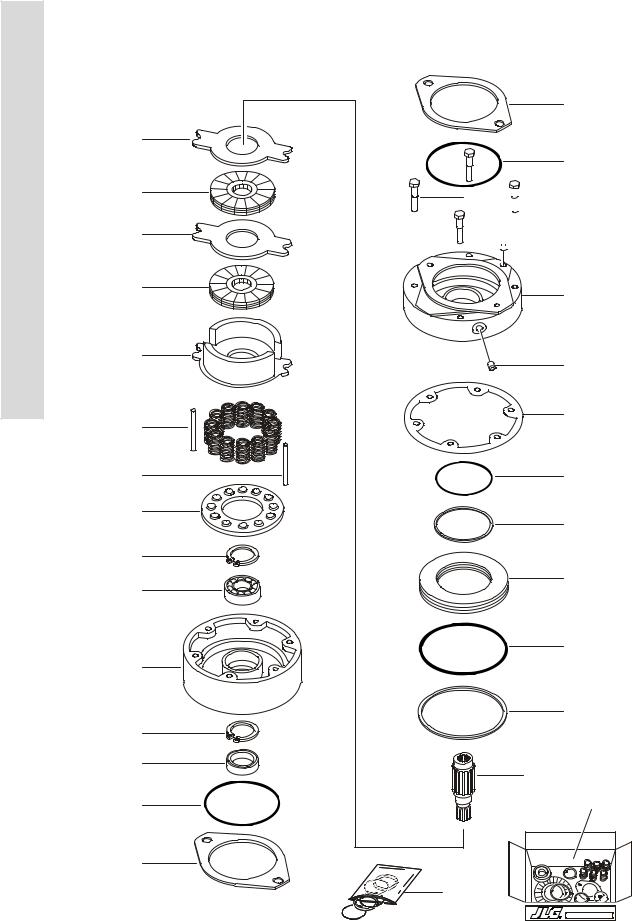
FIGURE 1-6. DRIVE BRAKE ASSEMBLY
7
6
7
6
5
3
12
12
2
16
15
4
14
13
23
22
22
23
9 |
|
|
|
9 |
|
|
|
||||
|
|
|
|
|
 24
24
10
11
8
20
17
21
19
18
1
27 51
26A
26B
GENUINE PARTS
1-18 |
3120841 |

SECTION 1 FRAME
.
FIGURE 1-6. DRIVE BRAKE ASSEMBLY
FIG & ITEM # |
PART NUMBER |
|
DESCRIPTION |
QTY. |
REV. |
|
|
|
|
|
|
|
|
DRIVE BRAKE ASSEMBLY OPTIONS: |
Ref. |
|
|
|
0920084 |
Prior to S/N 0300033476 |
Ref. |
A |
|
|
0920110 |
S/N 0300033476 to S/N 0300056536 |
Ref. |
C |
|
1 |
7011712 |
Shaft Options: |
1 |
|
|
2 |
|
Guide, Spring Options: |
1 |
|
|
|
7011717 |
0920084 |
Brake (Prior to S/N 0300033476) |
|
|
|
7018606 |
0920110 |
Brake (S/N 0300033476 to S/N 0300056536) |
|
|
3 |
|
Spring Options: |
A/R |
|
|
|
7007979 |
0920084 |
Brake (Inner) (Prior to S/N 0300033476) |
6 |
|
|
7007980 |
0920084 |
Brake (Outer) (Prior to S/N 0300033476) |
6 |
|
|
7007970 |
0920110 |
Brake (Red) (S/N 0300033476 to |
6 |
|
|
|
S/N 0300056536) |
|
|
|
|
7018602 |
0920110 |
Brake (Blue) (S/N 0300033476 to |
3 |
|
|
|
S/N 0300056536) |
|
|
|
4 |
|
Housing Options: |
1 |
|
|
|
7011713 |
0920084 |
Brake (Prior to S/N 0300033476) |
|
|
|
7018605 |
0920110 |
Brake (S/N 0300033476 to S/N 0300056536) |
|
|
5 |
|
Return Plate & Separator Assembly Options: |
A/R |
|
|
|
See Note |
Return, Plate - 0920084 Brake (Prior to |
1 |
|
|
|
|
S/N 0300033476) (Note: Use Item 27) |
|
|
|
|
7011715 |
Separator Assy - 0920084 Brake (Prior to |
2 |
|
|
|
|
S/N 0300033476) |
|
|
|
|
7011714 |
Pin |
|
4 |
|
|
7007983 |
Separator |
2 |
|
|
|
See Note |
Return Plate & Separator - 0920110 Brake (S/N |
1 |
|
|
|
|
0300033476 to S/N 0300056536) (Note: Use Item 27) |
|
|
|
6 |
See Note |
Rotor (Note: Use Item 27) |
2 |
|
|
7 |
See Note |
Stator (Note: Use Item 27) |
2 |
|
|
8 |
See Note |
Seal, Case (Note: Use Item 26A, 26B or 27) |
1 |
|
|
9 |
|
Bolt, Washer Head Options: |
4 |
|
|
|
7007985 |
0920084 |
Brake (Prior to S/N 0300033476) |
|
|
|
7018607 |
0920110 |
Brake (S/N 0300033476 to S/N 0300056536) |
|
|
10 |
7007986 |
Cover |
|
1 |
|
11 |
|
Hardware Options: |
1 |
|
|
|
7000796 |
Screw, Bleeder (Prior to S/N 0300033906) |
|
|
|
|
7018609 |
Plug, Pipe (S/N 0300033906 to S/N 0300056536) |
|
|
|
12 |
7007987 |
Pin, Dowel |
|
2 |
|
13 |
See Note |
Seal, Oil (Note: Use Item 26A or 26B) |
1 |
|
|
14 |
7011716 |
Ring, Retaining |
1 |
|
|
15 |
Use 2900768 |
Bearing |
|
1 |
|
16 |
7007977 |
Ring, Retaining |
1 |
|
|
17 |
Use 2900766 |
Ring, Back-Up |
1 |
|
|
18 |
Use 2900766 |
Ring, Back-Up |
1 |
|
|
19 |
Use 2900766 |
O-Ring |
|
1 |
|
20 |
Use 2900766 |
O-Ring |
|
1 |
|
21 |
|
Piston Options: |
1 |
|
|
|
7007923 |
0920084 |
Brake (Prior to S/N 0300033476) |
|
|
|
7018603 |
0920110 |
Brake (S/N 0300033476 to S/N 0300056536) |
|
|
|
|
|
|
|
|
S E C T I O N
1
F
R A M E
3120841 |
1-19 |

S E C T I O N
1
F
R A M E
SECTION 1 FRAME
FIGURE 1-6. DRIVE BRAKE ASSEMBLY
FIG & ITEM # |
PART NUMBER |
DESCRIPTION |
QTY. |
REV. |
|
|
|
|
|
22 |
7007933 |
Gasket |
2 |
|
23 |
See Note |
O-Ring (Note: Use Item 26A, 26B or 27) |
2 |
|
24 |
7007924 |
Plug, Pipe |
1 |
|
25 |
Not Used |
|
|
|
26 |
|
Seal Kit Options: |
1 |
|
26A |
2900766 |
Seal Kit (Includes Items 8,13,17,18,19,20,22 & 23) |
|
|
26B |
2900768 |
Seal Kit (Includes Items 8,13,15,22 & 23) |
|
|
27 |
|
Lining Kit Options: (Includes Items 5,6,7,8,22 & 23) |
1 |
|
|
2900767 |
0920084 Brake (Prior to S/N 0300033476) |
|
|
|
7018608 |
0920110 Brake (S/N 0300033476 to S/N 0300056536) |
|
|
|
|
DRIVE BRAKE ASSEMBLY (NOT SHOWN) (S/N 0300056536 |
Ref. |
B |
|
|
TO S/N 0300069000) |
|
|
|
|
NOTE: WAS P/N 0920117 - USE P/N 0920119 AS |
|
|
|
|
REPLACEMENT. |
|
|
51 |
7018612 |
Kit, Repair - 0920117 & 0920119 Brakes |
1 |
|
|
7000731 |
Gasket, Mounting Face |
1 |
|
|
|
Note: No other parts available. |
Ref. |
|
|
|
|
|
|
1-20 |
3120841 |
|
|
SECTION 1 FRAME |
|
|
|
S |
|
FIGURE 1-6. DRIVE BRAKE ASSEMBLY |
|
|
|
|
|||
|
|
|
|
|
|
E |
|
FIG & ITEM # |
PART NUMBER |
DESCRIPTION |
QTY. |
REV. |
|
C |
|
|
|
|
|||||
|
|
|
|
|
|
T |
|
|
|
|
|
|
|
|
|
|
|
|
|
|
|
I |
|
|
|
|
|
|
|
O |
|
|
|
|
|
|
|
N |
|
|
|
|
|
|
|
1 |
|
|
|
|
|
|
|
F |
|
|
|
|
|
|
|
R |
|
|
|
|
|
|
|
A |
|
|
|
|
|
|
|
M |
|
|
|
|
|
|
|
E |
|
|
|
|
|
|
|
|
|
|
|
|
|
|
|
|
|
3120841 |
1-21 |
S E C T I O N
1
F
R A M E
SECTION 1 FRAME
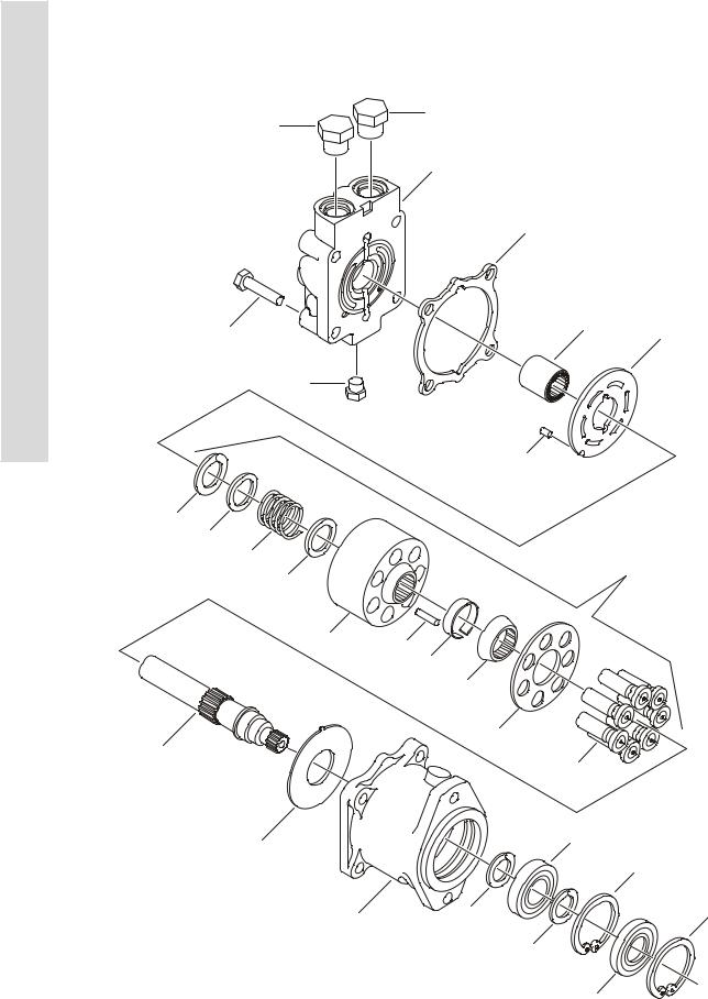
FIGURE 1-7. DRIVE MOTOR ASSEMBLY - SUNSTRAND (2WD)
14
14
12
5
15 |
8 |
6 |
|
|
13 |
|
|
|
9 |
20 |
|
|
|
19 |
|
|
|
18 |
|
|
17 |
21 |
|
|
|
|
|
|
|
23 |
|
26 |
|
|
|
|
|
|
|
24 |
|
|
|
25 |
|
|
|
|
27 |
11 |
|
|
22 |
|
|
|
|
7 |
|
|
3 |
|
|
|
|
|
|
|
2 |
|
16 |
4 |
1 |
|
|
|
|
|
|
|
4 |
|
|
|
10 |
1-22 |
3120841 |
Loading...