


45e
Table of contents
 Loading...
CORPORATE OFFICE
JLG INDUSTRIES, INC.
1 JLG Drive
McConnellsburg, PA.
17233-9533
USA
Telephone: (717) 485-5161
Fax: (717) 485-6417
Models
30e
35e
n35e
40e
n40e
45e
3120861
October 1, 2001
SERVICE & MAINTENANCE
WWW.JLG.COM

JLG Industries (Australia)
P.O. Box 5119
11 Bolwarra Road
Port Macquarie
N.S.W. 2444
Australia
Phone: (61) 2 65 811111
Fax: (61) 2 65 810122
JLG Industries (UK)
Unit 12, Southside
Bredbury Park Industrial Estate
Bredbury
Stockport
SK6 2sP
England
Phone: (44) 870 200 7700
Fax: (44) 870 200 7711
JLG Deutschland GmbH
Max Planck Strasse 21
D-27721 Ritterhude/lhlpohl
Bei Bremen
Germany
Phone: (49) 421 693 500
Fax: (49) 421 693 5035
JLG Industries (Italia)
Via Po. 22
20010 Pregnana Milanese - MI
Italy
Phone: (39) 02 9359 5210
Fax: (39) 02 9359 5845
JLG Latino Americana Ltda.
Rua Eng. Carlos Stevenson,
80-Suite 71
13092-310 Campinas-SP
Brazil
Phone: (55) 19 3295 0407
Fax: (55) 19 3295 1025
JLG Europe B.V.
Jupiterstraat 234
2132 HJ Foofddorp
The Netherlands
Phone: (31) 23 565 5665
Fax: (31) 23 557 2493
JLG Industries (Norge AS)
Sofeimyrveien 12
N-1412 Sofienyr
Norway
Phone: (47) 6682 2000
Fax: (47) 6682 2001
JLG Polska
UI. Krolewska
00-060 Warsawa
Poland
Phone: (48) 91 4320 245
Fax: (48) 91 4358 200
JLG Industries (Europe)
Kilmartin Place,
Tan n o ch s id e Pa r k
Uddingston G71 5PH
Scotland
Phone: (44) 1 698 811005
Fax: (44) 1 698 811055
JLG Industries (Pty) Ltd.
Unit 1, 24 Industrial Complex
Herman Street
Meadowdale
Germiston
South Africa
Phone: (27) 11 453 1334
Fax: (27) 11 453 1342
Plataformas Elevadoras
JLG Iberica, S.L .
Trapadella, 2
P. I . C a s t e l l b i s b a l S u r
08755Castellbisbal
Spain
Phone: (34) 93 77 24700
Fax: (34) 93 77 11762
JLG Industries (Sweden)
Enkopingsvagen 150
Box 704
SE - 175 27 Jarfalla
Sweden
Phone: (46) 8 506 59500
Fax: (46) 8 506 59534

INTRODUCTION
3120861 – JLG Lift – A-1
SECTION A. INTRODUCTION - MAINTENANCE SAFETY
PRECAUTIONS
A GENERAL
This section contains the general safety precautions which
must be observed during maintenance of the aerial plat-
form. It is of utmost importance that maintenance person-
nel pay strict attention to these warnings and precautions
to avoid possible injury to themselves or others, or dam-
age to the equipment. A maintenance program must be
followed to ensure that the machine is safe to operate.
MODIFICATION OF THE MACHINE WITHOUT CERTIFICATION BY
A RESPONSIBLE AUTHORITY THAT THE MACHINE IS AT LEAST
AS SAFE AS ORIGINALLY MANUFACTURED, IS A SAFETY VIOLA-
TION.
The specific precautions to be observed during mainte-
nance are inserted at the appropriate point in the manual.
These precautions are, for the most part, those that apply
when servicing hydraulic and larger machine component
parts.
Your safety, and that of others, is the first consideration
when engaging in the maintenance of equipment. Always
be conscious of weight. Never attempt to move heavy
parts without the aid of a mechanical device. Do not allow
heavy objects to rest in an unstable position. When raising
a portion of the equipment, ensure that adequate support is
provided.
SINCE THE MACHINE MANUFACTURER HAS NO DIRECT CON-
TROL OVER THE FIELD INSPECTION AND MAINTENANCE,
SAFETY IN THIS AREA RESPONSIBILITY OF THE OWNER/OPER-
ATOR.
B HYDRAULIC SYSTEM SAFETY
It should be noted that the machines hydraulic systems
operate at extremely high potentially dangerous pressures.
Every effort should be made to relieve any system pres-
sure prior to disconnecting or removing any portion of the
system.
Relieve system pressure by cycling the applicable control
several times with the engine stopped and ignition on, to
direct any line pressure back into the reservoir. Pressure
feed lines to system components can then be disconnected
with minimal fluid loss.
C MAINTENANCE
FAILURE TO COMPLY WITH SAFETY PRECAUTIONS LISTED IN
THIS SECTION MAY RESULT IN MACHINE DAMAGE, PERSONNEL
INJURY OR DEATH AND IS A SAFETY VIOLATION.
• NO SMOKING IS MANDATORY. NEVER REFUEL DUR-
ING ELECTRICAL STORMS. ENSURE THAT FUEL
CAP IS CLOSED AND SECURE AT ALL OTHER
TIMES.
• REMOVE ALL RINGS, WATCHES AND JEWELRY
WHEN PERFORMING ANY MAINTENANCE.
• DO NOT WEAR LONG HAIR UNRESTRAINED, OR
LOOSE-FITTING CLOTHING AND NECKTIES WHICH
ARE APT TO BECOME CAUGHT ON OR ENTANGLED
IN EQUIPMENT.
• OBSERVE AND OBEY ALL WARNINGS AND CAU-
TIONS ON MACHINE AND IN SERVICEMANUAL.
• KEEP OIL, GREASE, WATER, ETC. WIPED FROM
STANDING SURFACES AND HAND HOLDS.
• USE CAUTION WHEN CHECKING A HOT, PRESSUR-
IZED COOLANT SYSTEM.
• NEVER WORK UNDER AN ELEVATED BOOM UNTIL
BOOM HAS BEEN SAFELY RESTRAINED FROM ANY
MOVEMENT BY BLOCKING OR OVERHEAD SLING,
OR BOOM SAFETY PROP HAS BEEN ENGAGED.
• BEFORE MAKING ADJUSTMENTS, LUBRICATING OR
PERFORMING ANY OTHER MAINTENANCE, SHUT
OFF ALL POWER CONTROLS.
• BATTERY SHOULD ALWAYS BE DISCONNECTED-
DURING REPLACEMENT OF ELECTRICAL COMPO-
NENTS.
• KEEP ALL SUPPORT EQUIPMENT AND ATTACH-
MENTS STOWED IN THEIR PROPER PLACE.
• USE ONLY APPROVED, NONFLAMMABLE CLEANING
SOLVENTS.

INTRODUCTION
A-2 – JLG Lift – 3120861
REVISON LOG
March, 1989 - Original Issue
October, 1994 - Revised
August, 1997 - Revised
January, 1999 - Revised
June, 1999 -Revised
October 1, 2001 -Revised

3120743 – JLG Lift – i
TABLE OF CONTENTS
SUBJECT - SECTION, PARAGRAPH PAGE NO.
IINTRODUCTION - MAINTENANCE SAFETY PRECAUTIONS . . . . . . . . . . . . . . . . . . . . . . . . . . . . . . . . . . . . . . . . . .A-1
EFFECTIVITY CHANGES . . . . . . . . . . . . . . . . . . . . . . . . . . . . . . . . . . . . . . . . . . . . . . . . . . . . . . . . . . . . . . . . . . . . . . .A-2
SECTION 1 - SPECIFICATIONS
1.1 CAPACITIES. . . . . . . . . . . . . . . . . . . . . . . . . . . . . . . . . . . . . . . . . . . . . . . . . . . . . . . . . . . . . . . . . . .1-1
1.2 COMPONENT DATA. . . . . . . . . . . . . . . . . . . . . . . . . . . . . . . . . . . . . . . . . . . . . . . . . . . . . . . . . . . .1-1
1.3 PERFORMANCE DATA. . . . . . . . . . . . . . . . . . . . . . . . . . . . . . . . . . . . . . . . . . . . . . . . . . . . . . . . . .1-1
1.4 TORQUE SPECIFICATIONS. . . . . . . . . . . . . . . . . . . . . . . . . . . . . . . . . . . . . . . . . . . . . . . . . . . . . .1-3
1.5 LUBRICATION. . . . . . . . . . . . . . . . . . . . . . . . . . . . . . . . . . . . . . . . . . . . . . . . . . . . . . . . . . . . . . . . .1-3
1.6 PRESSURE SETTINGS. . . . . . . . . . . . . . . . . . . . . . . . . . . . . . . . . . . . . . . . . . . . . . . . . . . . . . . . . .1-4
1.7 CYLINDER SPECIFICATIONS. . . . . . . . . . . . . . . . . . . . . . . . . . . . . . . . . . . . . . . . . . . . . . . . . . . . .1-4
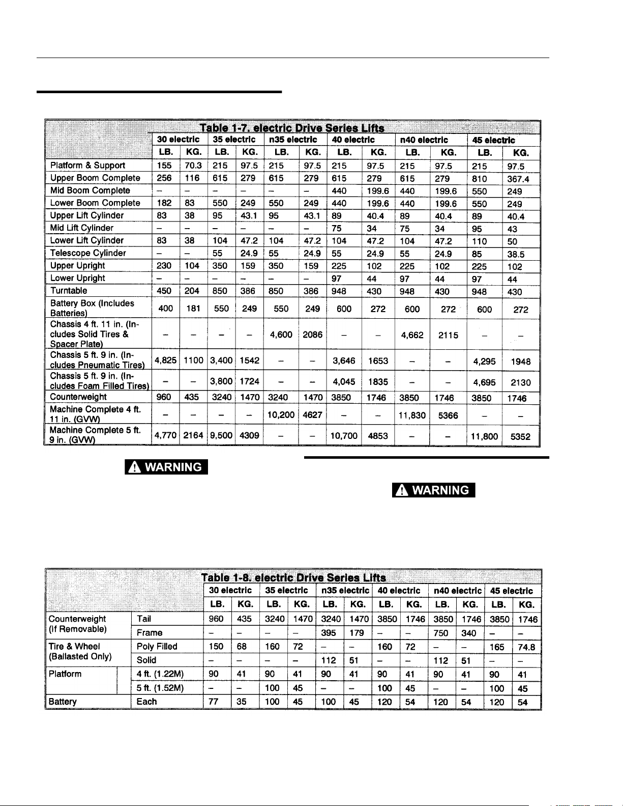
1.8 MAJOR COMPONENT WEIGHTS. . . . . . . . . . . . . . . . . . . . . . . . . . . . . . . . . . . . . . . . . . . . . . . . . .1-5
1.9 CRITICAL STABILITY WEIGHTS. . . . . . . . . . . . . . . . . . . . . . . . . . . . . . . . . . . . . . . . . . . . . . . . . . .1-6
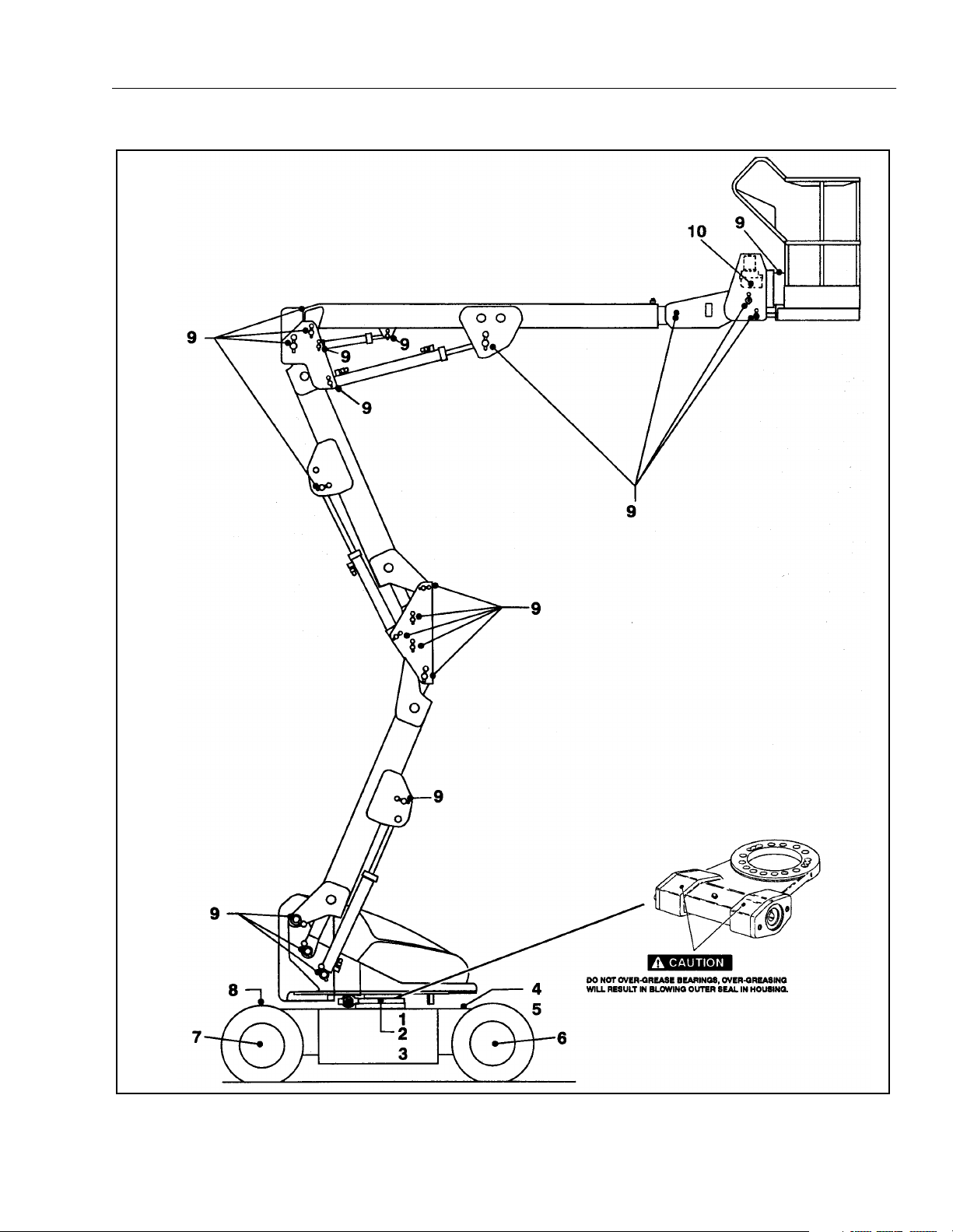
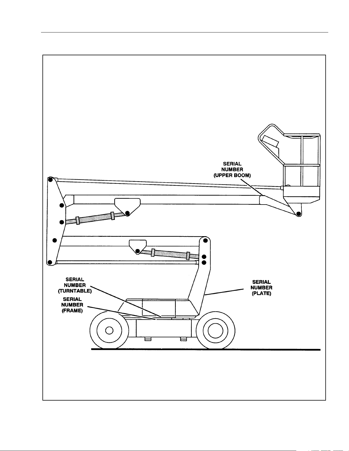
1.10 SERIAL NUMBER LOCATIONS. (See Figure 1-3) . . . . . . . . . . . . . . . . . . . . . . . . . . . . . . . . . . . . .1-6
SECTION 2 - PROCEDURES
2.1 GENERAL. . . . . . . . . . . . . . . . . . . . . . . . . . . . . . . . . . . . . . . . . . . . . . . . . . . . . . . . . . . . . . . . . . . . .2-1
2.2 SERVICING AND MAINTENANCE GUIDELINES.. . . . . . . . . . . . . . . . . . . . . . . . . . . . . . . . . . . . . . 2-1
2.3 LUBRICATION INFORMATION. . . . . . . . . . . . . . . . . . . . . . . . . . . . . . . . . . . . . . . . . . . . . . . . . . . .2-2
2.4 CYLINDERS - THEORY OF OPERATION.. . . . . . . . . . . . . . . . . . . . . . . . . . . . . . . . . . . . . . . . . . . .2-3
2.5 VALVES - THEORY OF OPERATION. . . . . . . . . . . . . . . . . . . . . . . . . . . . . . . . . . . . . . . . . . . . . . . . 2-3
2.6 MOTOR CONTROLLER. . . . . . . . . . . . . . . . . . . . . . . . . . . . . . . . . . . . . . . . . . . . . . . . . . . . . . . . . .2-4
2.7 WEAR PADS. . . . . . . . . . . . . . . . . . . . . . . . . . . . . . . . . . . . . . . . . . . . . . . . . . . . . . . . . . . . . . . . . . .2-10
2.8 BOOM MAINTENANCE. . . . . . . . . . . . . . . . . . . . . . . . . . . . . . . . . . . . . . . . . . . . . . . . . . . . . . . . . .2-10
2.9 CYLINDER CHECKING PROCEDURES.. . . . . . . . . . . . . . . . . . . . . . . . . . . . . . . . . . . . . . . . . . . . .2-15
2.10 CYLINDER REPAIR.. . . . . . . . . . . . . . . . . . . . . . . . . . . . . . . . . . . . . . . . . . . . . . . . . . . . . . . . . . . . .2-20
2.11 CYLINDER REMOVAL AND INSTALLATION.. . . . . . . . . . . . . . . . . . . . . . . . . . . . . . . . . . . . . . . . .2-26
2.12 TILT INDICATOR SWITCH LEVELING PROCEDURE. (If Equipped.) . . . . . . . . . . . . . . . . . . . . . .2-29
2.13 BOOM LIMIT SWITCHES. . . . . . . . . . . . . . . . . . . . . . . . . . . . . . . . . . . . . . . . . . . . . . . . . . . . . . . . .2-29
2.14 POWER TRACK REMOVAL PROCEDURE (35/n35/40/n40/45 electric). . . . . . . . . . . . . . . . . . . . . 2-29
2.15 PRESSURE SETTING PROCEDURES. (In Sequence) (See Figure 2-29) . . . . . . . . . . . . . . . . . .2-29
2.16 SWING BEARING. . . . . . . . . . . . . . . . . . . . . . . . . . . . . . . . . . . . . . . . . . . . . . . . . . . . . . . . . . . . . . .2-35
2.17 DRIVE TORQUE HUB. (See Figure 2-34) . . . . . . . . . . . . . . . . . . . . . . . . . . . . . . . . . . . . . . . . . . . .2-41
2.18 DRIVE BRAKE ASSEMBLY. . . . . . . . . . . . . . . . . . . . . . . . . . . . . . . . . . . . . . . . . . . . . . . . . . . . . . .2-44
2.19 MID AND LOWER LIFT CYLINDER BLEEDING PROCEDURE. (40/n40/45 electric) . . . . . . . . . .2-46
2.20 BOOM SYNCHRONIZING PROCEDURE. (40/n40/45 electric) . . . . . . . . . . . . . . . . . . . . . . . . . . .2-46
2.21 FREE WHEELING PROCEDURE. . . . . . . . . . . . . . . . . . . . . . . . . . . . . . . . . . . . . . . . . . . . . . . . . . .2-47
2.22 FOOTSWITCH ADJUSTMENT. . . . . . . . . . . . . . . . . . . . . . . . . . . . . . . . . . . . . . . . . . . . . . . . . . . . .2-47
2.23 AXLE DRAIN PLATES . . . . . . . . . . . . . . . . . . . . . . . . . . . . . . . . . . . . . . . . . . . . . . . . . . . . . . . . . . .2-47
2.24 PREVENTIVE MAINTENANCE AND INSPECTION SCHEDULE. . . . . . . . . . . . . . . . . . . . . . . . . . .2-48
SECTION 3 - TROUBLESHOOTING
3.1 GENERAL. . . . . . . . . . . . . . . . . . . . . . . . . . . . . . . . . . . . . . . . . . . . . . . . . . . . . . . . . . . . . . . . . . . . .3-1
3.2 TROUBLESHOOTING INFORMATION.. . . . . . . . . . . . . . . . . . . . . . . . . . . . . . . . . . . . . . . . . . . . . .3-1
3.3 HYDRAULIC CIRCUIT CHECKS.. . . . . . . . . . . . . . . . . . . . . . . . . . . . . . . . . . . . . . . . . . . . . . . . . . .3-1

ii – JLG Lift – 3120743
TABLE OF CONTENTS (Continued)
FIGURE NO. TITLE PAGE NO.
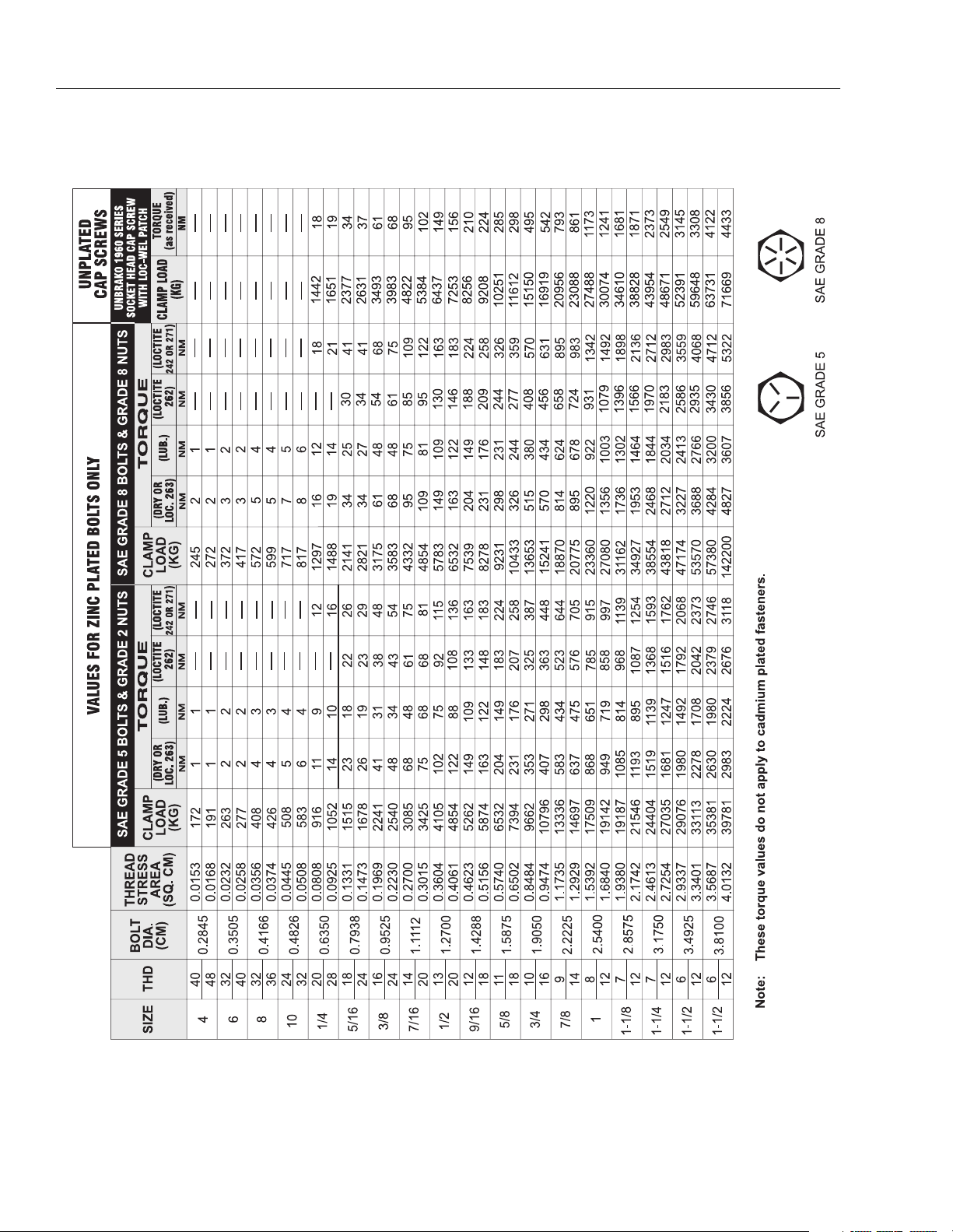
1-1. Torque Chart. . . . . . . . . . . . . . . . . . . . . . . . . . . . . . . . . . . . . . . . . . . . . . . . . . . . . . . . . . . . . . . . . .1-7
1-2. Lubrication Chart - 30 electric. (Sheet 1 of 6). . . . . . . . . . . . . . . . . . . . . . . . . . . . . . . . . . . . . . . . .1-8
1-2. Lubrication Chart - 30 electric. (Sheet 2 of 6). . . . . . . . . . . . . . . . . . . . . . . . . . . . . . . . . . . . . . . . .1-9
1-2. Lubrication Chart - 35/n35 electric. (Sheet 3 of 6). . . . . . . . . . . . . . . . . . . . . . . . . . . . . . . . . . . . . .1-10
1-2. Lubrication Chart - 35/n35 electric. (Sheet 4 of 6). . . . . . . . . . . . . . . . . . . . . . . . . . . . . . . . . . . . . .1-11
1-2. Lubrication Chart - 40/n40/45 electric. (Sheet 5 of 6). . . . . . . . . . . . . . . . . . . . . . . . . . . . . . . . . . .1-12
1-2. Lubrication Chart - 40/n40/45 electric. (Sheet 6 of 6). . . . . . . . . . . . . . . . . . . . . . . . . . . . . . . . . . .1-13
1-3. Serial Number Locations - 30 electric. (Sheet 1 of 3). . . . . . . . . . . . . . . . . . . . . . . . . . . . . . . . . . .1-14
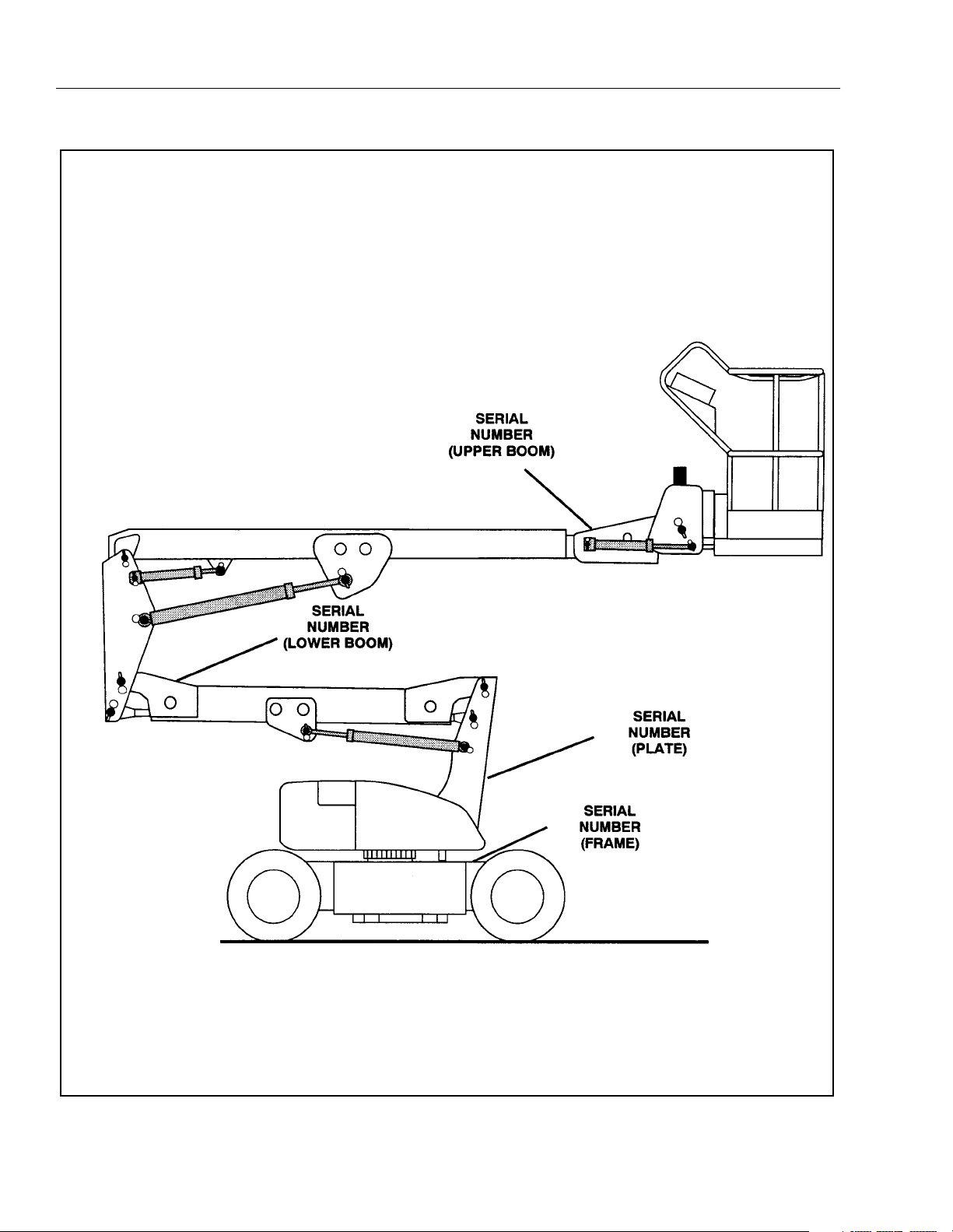
1-3. Serial Number Locations - 35/n35 electric. (Sheet 2 of 3).. . . . . . . . . . . . . . . . . . . . . . . . . . . . . . .1-15
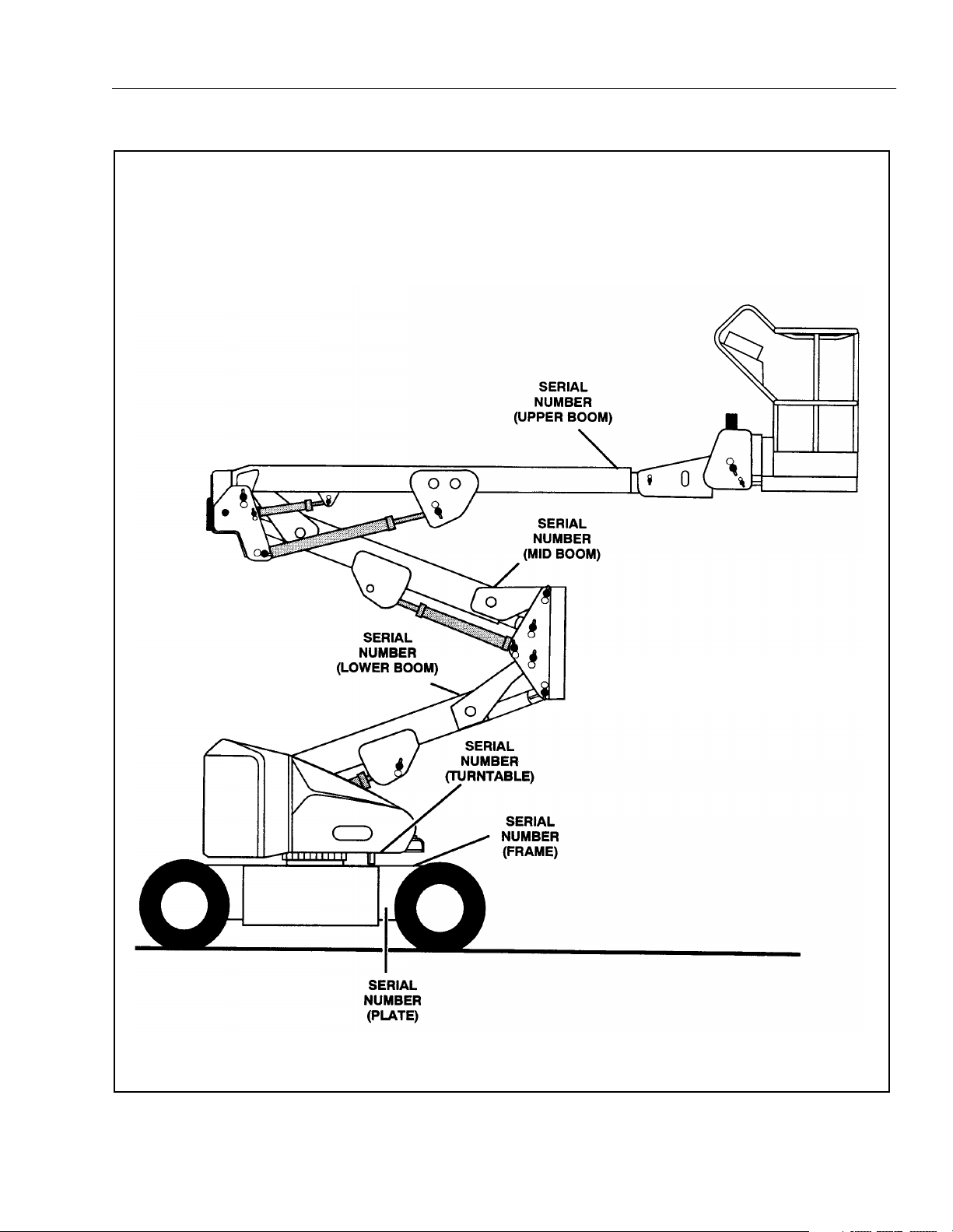
1-3. Serial Number Locations - 40/n40/45 electric. (Sheet 3 of 3). . . . . . . . . . . . . . . . . . . . . . . . . . . . .1-16
2-1. Sevcon Controller Troubleshooting Flow Charts. (Sheet 1 of 4).. . . . . . . . . . . . . . . . . . . . . . . . . .2-6
2-1. Sevcon Controller Troubleshooting Flow Charts. (Sheet 2 of 4).. . . . . . . . . . . . . . . . . . . . . . . . . .2-7
2-1. Sevcon Controller Troubleshooting Flow Charts. (Sheet 3 of 4).. . . . . . . . . . . . . . . . . . . . . . . . . .2-8
2-1. Sevcon Controller Troubleshooting Flow Charts. (Sheet 4 of 4).. . . . . . . . . . . . . . . . . . . . . . . . . .2-9
2-2. Location and Thickness of Wear Pads. . . . . . . . . . . . . . . . . . . . . . . . . . . . . . . . . . . . . . . . . . . . . .2-10
2-3. Locations of Components - Platform Support (Model 30). . . . . . . . . . . . . . . . . . . . . . . . . . . . . . . 2-10
2-4. Location of Components - Removal of Base Boom. (Model 30) . . . . . . . . . . . . . . . . . . . . . . . . . . 2-11
2-5. Location of Components - Platform Support. (Models 35/n35/40/n40/45) . . . . . . . . . . . . . . . . . .2-12
2-6. Location of Components - Slave Leveling Cylinder.. . . . . . . . . . . . . . . . . . . . . . . . . . . . . . . . . . . . 2-12
2-7. Location of Components - Removal of Base Boom. (Models 35/n35/40/n40/45) . . . . . . . . . . . . .2-12
2-8. Location of Components - Aft End of Fly Boom Wear Pad Adjustments. . . . . . . . . . . . . . . . . . . . 2-13
2-9. Location of Components - Removal of Telescope Cyllinder.. . . . . . . . . . . . . . . . . . . . . . . . . . . . .2-13
2-10. Location of Components - Front Base Boom Wear Pad Adjustments. . . . . . . . . . . . . . . . . . . . . . 2-13
2-11. Boom Prop Configurations - 30 electric. (Sheet 1 of 3) . . . . . . . . . . . . . . . . . . . . . . . . . . . . . . . . .2-17
2-11. Boom Prop Configurations - 35/n35 electric. (Sheet 2 of 3) . . . . . . . . . . . . . . . . . . . . . . . . . . . . .2-18
2-11. Boom Prop Configurations - 35/n35 electric. (Sheet 3 of 3) . . . . . . . . . . . . . . . . . . . . . . . . . . . . .2-19
2-12. Removal of Cylinder Retainer.. . . . . . . . . . . . . . . . . . . . . . . . . . . . . . . . . . . . . . . . . . . . . . . . . . . . .2-20
2-13. Removal of Set Screws. . . . . . . . . . . . . . . . . . . . . . . . . . . . . . . . . . . . . . . . . . . . . . . . . . . . . . . . . . 2-21
2-14. Removal of Seals and O-Rings. . . . . . . . . . . . . . . . . . . . . . . . . . . . . . . . . . . . . . . . . . . . . . . . . . . .2-21
2-15. Removal of Piston Seals. . . . . . . . . . . . . . . . . . . . . . . . . . . . . . . . . . . . . . . . . . . . . . . . . . . . . . . . .2-21
2-16. Rod Seal Installation.. . . . . . . . . . . . . . . . . . . . . . . . . . . . . . . . . . . . . . . . . . . . . . . . . . . . . . . . . . . .2-22
2-17. Wiper Seal Installation. . . . . . . . . . . . . . . . . . . . . . . . . . . . . . . . . . . . . . . . . . . . . . . . . . . . . . . . . . .2-22
2-18. Poly-Pak Piston Seal Installation. . . . . . . . . . . . . . . . . . . . . . . . . . . . . . . . . . . . . . . . . . . . . . . . . . .2-22
2-19. "O"-Ring Installation. . . . . . . . . . . . . . . . . . . . . . . . . . . . . . . . . . . . . . . . . . . . . . . . . . . . . . . . . . . . .2-22
2-20. Piston Seal Kit Installation. . . . . . . . . . . . . . . . . . . . . . . . . . . . . . . . . . . . . . . . . . . . . . . . . . . . . . . .2-22
2-21. Steer Cylinder Piston Installation. . . . . . . . . . . . . . . . . . . . . . . . . . . . . . . . . . . . . . . . . . . . . . . . . . .2-23
2-22. Installing Retainer Ring on Telescope Cylinder Barrel. . . . . . . . . . . . . . . . . . . . . . . . . . . . . . . . . .2-23
2-23. Lift Cylinder Assembly. . . . . . . . . . . . . . . . . . . . . . . . . . . . . . . . . . . . . . . . . . . . . . . . . . . . . . . . . . . 2-24
2-24. Upper Boom Lift Cylinder Removal. . . . . . . . . . . . . . . . . . . . . . . . . . . . . . . . . . . . . . . . . . . . . . . . .2-26
2-25. Mid Boom Lift Cylinder Removal. . . . . . . . . . . . . . . . . . . . . . . . . . . . . . . . . . . . . . . . . . . . . . . . . . .2-27
2-26. Lower Boom Lift Cyllinder Removal.. . . . . . . . . . . . . . . . . . . . . . . . . . . . . . . . . . . . . . . . . . . . . . . . 2-27
2-27. Upper Telescope Cylinder Removal. . . . . . . . . . . . . . . . . . . . . . . . . . . . . . . . . . . . . . . . . . . . . . . .2-28
2-28. Tilt Switch. . . . . . . . . . . . . . . . . . . . . . . . . . . . . . . . . . . . . . . . . . . . . . . . . . . . . . . . . . . . . . . . . . . . .2-29
2-29. Pressure Setting Procedures - 30 electric. (Sheet 1 of 3) . . . . . . . . . . . . . . . . . . . . . . . . . . . . . . .2-32
2-29. Pressure Setting Procedures - 35/n35 electric. (Sheet 2 of 3) . . . . . . . . . . . . . . . . . . . . . . . . . . . .2-33
2-29. Pressure Setting Procedures - 40/n40/45 electric. (Sheet 3 of 3) . . . . . . . . . . . . . . . . . . . . . . . . .2-34
2-30. Swing Bearing Feeler Gauge Check. . . . . . . . . . . . . . . . . . . . . . . . . . . . . . . . . . . . . . . . . . . . . . . . 2-35
2-31. Swing Bearing Tolerance Boom Placement - 30/35/n35 electric. . . . . . . . . . . . . . . . . . . . . . . . . .2-36
2-31. Swing Bearing Tolerance Boom Placement - 40/n40/45 electric. . . . . . . . . . . . . . . . . . . . . . . . . .2-38
2-32. Swing Bearing Tolerance Measuring Point. . . . . . . . . . . . . . . . . . . . . . . . . . . . . . . . . . . . . . . . . . .2-38
2-33. Swing Bearing Torquing Sequence. . . . . . . . . . . . . . . . . . . . . . . . . . . . . . . . . . . . . . . . . . . . . . . . . 2-40
2-34. Drive Hub Assembly - 30/35/n35/40/n40/45. . . . . . . . . . . . . . . . . . . . . . . . . . . . . . . . . . . . . . . . . .2-43
2-35. Drive Brake Assembly - 30/35/n35/40/n40/45. . . . . . . . . . . . . . . . . . . . . . . . . . . . . . . . . . . . . . . . . 2-45
2-36. Port "P" Location.. . . . . . . . . . . . . . . . . . . . . . . . . . . . . . . . . . . . . . . . . . . . . . . . . . . . . . . . . . . . . . .2-46
2-37. Synchronizing Valve. . . . . . . . . . . . . . . . . . . . . . . . . . . . . . . . . . . . . . . . . . . . . . . . . . . . . . . . . . . . .2-47
2-38. Upright Leveling. . . . . . . . . . . . . . . . . . . . . . . . . . . . . . . . . . . . . . . . . . . . . . . . . . . . . . . . . . . . . . . .2-47

3120743 – JLG Lift – iii
TABLE OF CONTENTS
2-39. Drive Brake Release. . . . . . . . . . . . . . . . . . . . . . . . . . . . . . . . . . . . . . . . . . . . . . . . . . . . . . . . . . . . .2-47
2-40. Drive Axle Drain Plate.. . . . . . . . . . . . . . . . . . . . . . . . . . . . . . . . . . . . . . . . . . . . . . . . . . . . . . . . . . .2-48
3-1. Electrical Schematic 30 electric. (Sheet 1 of 4) . . . . . . . . . . . . . . . . . . . . . . . . . . . . . . . . . . . . . . .3-12
3-1. Electrical Schematic 30 electric. (Sheet 2 of 4) . . . . . . . . . . . . . . . . . . . . . . . . . . . . . . . . . . . . . . .3-13
3-1. Electrical Schematic 30 electric. (Sheet 3 of 4) . . . . . . . . . . . . . . . . . . . . . . . . . . . . . . . . . . . . . . .3-14
3-1. Electrical Schematic 30 electric. (Sheet 4 of 4) . . . . . . . . . . . . . . . . . . . . . . . . . . . . . . . . . . . . . . .3-15
3-2. Electrical Schematic 35/40/45 electric. (Sheet 1 of 4) . . . . . . . . . . . . . . . . . . . . . . . . . . . . . . . . . . 3-16
3-2. Electrical Schematic. 35/40/45 electric. (Sheet 2 of 4). . . . . . . . . . . . . . . . . . . . . . . . . . . . . . . . . . 3-17
3-2. Electrical Schematic. 35/40/45 electric. (Sheet 3 of 4). . . . . . . . . . . . . . . . . . . . . . . . . . . . . . . . . . 3-18
3-2. Electrical Schematic. 35/40/45 electric. (Sheet 4 of 4). . . . . . . . . . . . . . . . . . . . . . . . . . . . . . . . . . 3-19
3-3. Hydraulic Diagram - 30 electric. . . . . . . . . . . . . . . . . . . . . . . . . . . . . . . . . . . . . . . . . . . . . . . . . . . .3-20
3-4. Hydraulic Diagram - 35 electric. . . . . . . . . . . . . . . . . . . . . . . . . . . . . . . . . . . . . . . . . . . . . . . . . . . .3-21
3-5. Hydraulic Diagram - 40/45 electric.. . . . . . . . . . . . . . . . . . . . . . . . . . . . . . . . . . . . . . . . . . . . . . . . .3-22
TABLE NO. TITLE PAGE NO.
1-1 Hydraulic Oil. . . . . . . . . . . . . . . . . . . . . . . . . . . . . . . . . . . . . . . . . . . . . . . . . . . . . . . . . . . . . . . . .1-3
1-2 Lubrication Specifications. . . . . . . . . . . . . . . . . . . . . . . . . . . . . . . . . . . . . . . . . . . . . . . . . . . . . . . .1-3
1-3 Cylinder Specifications.. . . . . . . . . . . . . . . . . . . . . . . . . . . . . . . . . . . . . . . . . . . . . . . . . . . . . . . . . .1-4
1-4 Cylinder Specifications.. . . . . . . . . . . . . . . . . . . . . . . . . . . . . . . . . . . . . . . . . . . . . . . . . . . . . . . . . .1-4
1-5 Cylinder Specifications.. . . . . . . . . . . . . . . . . . . . . . . . . . . . . . . . . . . . . . . . . . . . . . . . . . . . . . . . . .1-4
1-6 Cylinder Specifications.. . . . . . . . . . . . . . . . . . . . . . . . . . . . . . . . . . . . . . . . . . . . . . . . . . . . . . . . . .1-5
2-1 Cylinder Piston Nut Torque Specifications. . . . . . . . . . . . . . . . . . . . . . . . . . . . . . . . . . . . . . . . . . .2-25
2-2 Holding Valve Torque Specifications. . . . . . . . . . . . . . . . . . . . . . . . . . . . . . . . . . . . . . . . . . . . . . . .2-25
2-3 PREVENTIVE MAINTENANCE AND INSPECTION SCHEDULE. . . . . . . . . . . . . . . . . . . . . . . . . . .2-49
3-1 PLATFORM ASSEMBLY - TROUBLESHOOTING . . . . . . . . . . . . . . . . . . . . . . . . . . . . . . . . . . . . . .3-2
3-2 BOOM ASSEMBLY - TROUBLESHOOTING . . . . . . . . . . . . . . . . . . . . . . . . . . . . . . . . . . . . . . . . . .3-3
3-2 BOOM ASSEMBLY - TROUBLESHOOTING . . . . . . . . . . . . . . . . . . . . . . . . . . . . . . . . . . . . . . . . .3-4
3-2 BOOM ASSEMBLY - TROUBLESHOOTING . . . . . . . . . . . . . . . . . . . . . . . . . . . . . . . . . . . . . . . . . .3-5
3-2 BOOM ASSEMBLY - TROUBLESHOOTING . . . . . . . . . . . . . . . . . . . . . . . . . . . . . . . . . . . . . . . . . .3-6
3-3 TURNTABLE ASSEMBLY - TROUBLESHOOTING . . . . . . . . . . . . . . . . . . . . . . . . . . . . . . . . . . . . .3-7
3-4 CHASSIS ASSEMBLY - TROUBLESHOOTING. . . . . . . . . . . . . . . . . . . . . . . . . . . . . . . . . . . . . . . .3-8
3-4 CHASSIS ASSEMBLY - TROUBLESHOOTING. . . . . . . . . . . . . . . . . . . . . . . . . . . . . . . . . . . . . . . .3-9
3-5 HYDRAULIC SYSTEM - TROUBLESHOOTING. . . . . . . . . . . . . . . . . . . . . . . . . . . . . . . . . . . . . . . .3-10
3-6 ELECTRICAL SYSTEM - TROUBLESHOOTING . . . . . . . . . . . . . . . . . . . . . . . . . . . . . . . . . . . . . . .3-11

iv – JLG Lift – 3120743
TABLE OF CONTENTS (Continued)
This page left intentionally blank.

SECTION 1 - SPECIFICATIONS
3120861 – JLG Lift – 1-1
SECTION 1. SPECIFICATIONS
1.1 CAPACITIES.
Hydraulic Oil Tank.
4.0 gallons (15.14 liters).
Hydraulic System.
Approximately 4.8 gallons (18.2 liters).
Torque Hubs (2).
17 ounces (0.5 liters).
1.2 COMPONENT DATA.
Battery Charger.
Input, 110 VAC,60 HZ.
Output, 48 VDC (23 Amps.).
Batteries (8).
6 Volt, 370 AmpHour (20 hour rate).
Drive System.
Drive Motor - 36 VDC, 4.1 H.P. @ 1880 rpm. continuous,
rotation - reversible.
Drive Brake- 24 VDC, spring-applied, electrically released.
Tires - 30 electric.
Tires - ST205 75R15, Load Range C, 6 Ply Rating, 70 psi
(4.9 kg/cm
2
).
Foam Filled - 205 75R15, 6 Ply Rating, 70 psi (4.9 kg/cm
2
).
Solid Tires - 26 x 7 x 20 Lug Tread Non marking Com-
pound. (Optional)
Tires - n35/n40 electric.
Solid Tires - 22 x 6 x 16 Lug Tread Dual Service Com-
pound.
Solid Tires - 22 x 6 x 16 Lug Tread Non marking Com-
pound. (Optional)
Tires - 35/40 electric. (Prior to March of 1996)
Tires - ST225 75R15, Load Range D, 8 Ply Rating, 80 psi
(5.5 kg/cm
2
).
Tires - ST225 75R15, Load Range D, 8 Ply Rating, Foam
Filled. (Optional)
Tires - 35/40 electric. (March of 1996 to Present)
Tires - G 78 - 15, Load Range E, 10 Ply Rating, 80 psi (5.5
kg/cm
2
).
Tires - G 78 - 15, Load Range E, 10 Ply Rating, Foam
Filled. (Optional)
Solid Tires - 22 x 6.5 x 16 Lug Tread Non marking Com-
pound. (Optional)
Tires 10 - 16.5 NHS, 8 Ply, 70 psi (4.9 kg/cm
2
).
Tires 10 - 16.5 NHS, 8 Ply, 70 psi (4.9 kg/cm
2
), Foam Filled
Tires - 45 electric.
Tires - LT215 85R16, Load Range E, 10 Ply Rating, 90 psi
(6.2 kg/cm
2
).
Tires - LT215 85R16, Load Range E, 10 Ply Rating, Foam
Filled. (Optional)
Tires 10 - 16.5 NHS, 8 Ply, 70 psi (4.9 kg/cm
2
).
Tires 10 - 16.5 NHS, 8 Ply, 70 psi (4.9 kg/cm
2
), Foam
Filled.
Hydraulic Filter.
Return, 10 Micron.
Hydraulic Pump/Electric Motor Assembly.
Motor - 48 VDC, 2.14 H.P. @ 2700 rpm.
Pump -1.6 cm
3
/rev.
Pump Output - 4.13 lpm @ 137.9 Bar.
1.3 PERFORMANCE DATA.
EE Rated, Certified By U/L.
Travel Speed.
30 electric - 6.4 kph.
35 electric - 4.8 kph.
n35 electric - 4.1 kph.
40 electric - 4.8 kph.
n40 electric - 4.1 kph.
45 electric - 4.2 kph.
Gradeability.
25%.
Maximum Slope
3%

SECTION 1 - SPECIFICATIONS
1-2 – JLG Lift – 3120861
Turning Radius (Inside).
30 electric - 1.33 m.
35 electric - 1.31 m.
n35 electric - 1.60 m.
40 electric - 1.31 m.
n40 electric - 1.60 m.
45 electric - 1.31 m.
Turning Radius (Outside).
30 electric - 3.63 m.
35 electric - 3.63 m.
n35 electric - 3.63 m.
40 electric - 3.63 m.
n40 electric - 3.63 m.
45 electric - 3.63 m.
Upper Boom Speed.
30 electric - Lift Up - 15 - 25 seconds.
30 electric - Lift Down - 17 - 27 seconds.
35/n35 electric - Lift Up - 40 - 50 seconds.
35/n35 electric - Lift Down - 32 - 42 seconds.
40/n40 electric - Lift Up - 40 - 50 seconds.
40/n40 electric - Lift Down - 59 - 69 seconds.
45 electric - Lift Up - 40 - 50 seconds.
45 electric - Lift Down - 39 - 49 seconds.
Lower Boom Speed.
30 electric - Lift Up - 16 - 26 seconds.
30 electric - Lift Down - 19 - 29 seconds.
35/n35 electric - Lift Up - 49 - 59 seconds.
35/n35 electric - Lift Down - 30 - 40 seconds.
40/n40 electric - Lift Up - 50 - 60 seconds.
40/n40 electric - Lift Down - 23 - 29 seconds.
45 electric - Lift Up - 58 - 68 seconds.
45 electric - Lift Down - 28 - 38 seconds.
Swing Speed - 360 Degrees.
30 electric - 55 - 65 seconds.
35/n35 electric - 65 - 75 seconds.
40/n40 electric - 85 - 95 seconds.
45 electric - 85 - 95 seconds.
Machine Weight.
30 electric - 2,164 kg.
35 electric - 4,309 kg.
n35 electric - 10,200 lb. (4,627 kg).
40 electric - 4,853 kg.
n40 electric - 5,366 kg.
45 electric - 5,352 kg.
Max. Tire Load.
30 electric - 1,161 kg.
35 electric - 1,624 kg.
n35 electric - 1,928 kg.
40 electric - 2,132 kg.
n40 electric - 2,343 kg.
45 electric - 2,656 kg.
Machine Height (stowed).
30 electric - 6 ft. 7.0 in. (2.0 m.).
35/n35 electric - 6 ft. 7.0 in. (2.0 m.).
40/n40 electric - 6 ft. 7.0 in. (2.0 m.).
45 electric - 6 ft. 7.0 in. (2.0 m.).
Machine Length (stowed).
30 electric - 4.75 m.
35/n35 electric - 5.18 m.
40 electric - 5.36 m.
n40 electric - 5.28 m.
45 electric - 5.69 m.
Up and Over Platform Height.
30 electric - 5.05 m.
35/n35 electric - 5.46 m.
40/n40 electric - 6.10 m.
45 electric - 7.49 m.
Horizontal Reach Up and Over.
30 electric - 4.09 m.
35/n35 electric - 6.25 m.
40/n40 electric - 6.25 m.
45 electric - 6.91 m.

SECTION 1 - SPECIFICATIONS
3120861 – JLG Lift – 1-3
Machine Width.
30 electric - 1.75 m.
35 electric - 1.75 m.
n35 electric - 1.50 m.
40 electric - 1.75 m.
n40 electric - 1.50 m.
45 electric - 1.75 m.
Wheel Base.
30 electric - 1.93 m.
35/n35 electric - 2.01 m.
40/n40 electric - 2.01 m.
45 electric - 2.01 m.
Working Height.
30 electric - 9.14 m.
35/n35 electric - 10.67 m.
40/n40 electric - 12.19 m.
45 electric - 13.72 m.
1.4 TORQUE SPECIFICATIONS.
NOTE: *Check swing bearing bolts for security after first 50
hours of operation and every 600 hours thereafter.
(See paragraph 2-16, - Swing Bearing.)
NOTE: When maintenance becomes necessary or a fas-
tener has loosened, refer to the Torque Chart, Figure
1-1, to determine proper torque value.
1.5 LUBRICATION.
Hydraulic Oil.
Table 1-1. Hydraulic Oil.
NOTE: Hydraulic oils must have anti-wear qualities at least
to API Service Classification GL-3, and sufficient
chemical stability for mobile hydraulic system ser-
vice. JLG Industries recommends Mobilfluid 424
hydraulic oil, which has an SAE viscosity index of
152.
NOTE: When temperatures remain consistently below 20
degrees (-7 degrees C), an amount of no. 2 diesel
fuel, not to exceed 20% of system capacity, may be
added to the hydraulic oil reservoir. This diesel fuel
will “thin” the hydraulic oil for easier cold weather
operation, and will almost completely dissipate from
the hydraulic system over a several month period of
time. When cold weather is past, it may be neces-
sary to drain and refill the hydraulic system to rid the
system of any remaining diesel fuel.
NOTE: Aside from JLG recommendations, it is not advisable
to mix oils of different brands or types, as they may
not contain the same required additives or be of
comparable viscosities. If use of hydraulic oil other
than Mobilfluid 424 is desired, contact JLG Indus-
tries for proper recommendations.
Description
Torque Value
(Dry)
Interval Hours
A. Bearing To
Chassis
See Note 50/600*
B. Bearing To
Tu r nt a b le
See Note 50/600*
C. Wheel Bolts 122 Nm 150
HYDRAULIC SYSTEM
OPERATING
TEMPERATURE RANGE
SAE VISCOSITY GRADE
0 F to 23 F (-18 C to -5 C) 10W
0 F to 210 F (-18 C to +99 C) 10W-20,10W-30
50 F to 210 F (+10 C to +9 9 C) 20W-20
SECTION 1 - SPECIFICATIONS
1-4 – JLG Lift – 3120861
Lubrication Specifications
Table 1-2. Lubrication Specifications.
*MPG may be substituted for these lubricants, if neces-
sary, but service intervals will be reduced.
NOTE: Refer to Lubrication Chart, Figure1-2, for specific
lubrication procedures.
1.6 PRESSURE SETTINGS.
NOTE: Model 30 electric.
Hydro-Air Valve 4640725.
Lift Down Relief - 900 psi (62 bar).
Articulate and Lift Down Relief - 725 psi (49.99 bar).
Swing Relief - 1000 psi (68.95 bar).
Hydro-Air Valve 4640726.
Steer Relief - 1100 psi (75.84 bar).
Main Relief at Pump - 2600 psi (179.27 bar).
NOTE: Model 35/n35 electric.
Hydro-Air Valve 4640843.
Upper Lift Down Relief - 600 psi (41.37 bar).
Lower Lift Down Relief - 600 psi (41.37 bar).
Swing Relief - 1000 psi (68.95 bar).
Telescope In Relief - 2150 psi (148.25 bar).
Platform Level Up Relief - 2500 psi (172.37 bar).
Platform Level Down Relief - 1200 psi (82.74 bar).
Hydro-Air Valve 4640726.
Steer Relief - 1500 psi (103.42 bar).
Main Relief at Pump - 2600 psi (179.27 bar).
NOTE: Model 40/n40/45 electric.
Hydro-Air Valve 4640797.
Upper Lift Down Relief - 650 psi (44.82 bar).
Mid/Lower Lift Down Relief - 1700 psi (117.21 bar).
Swing Relief - 1000 psi (68.95 bar).
Telescope In Relief - 2150 psi (148.25 bar).
Platform Level Up Relief - 2500 psi (172.37 bar).
Platform Level Down Relief - 1200 psi (82.74 bar).
Hydro-Air Valve 4640726.
Steer Relief - 2300 psi (158.59 bar).
Main Relief at Pump - 3200 psi (220.64 bar).
KEY SPECIFICATIONS
MPG Mul tipurpose Grease having a minimum drippin g point
of 350 F (178 C). Exc ellent water resistance and
adhesive qualities, and being of extreme pressure
type. (Timken OK 40 pound s minimum.)
EPGL Extreme Pressure Gear Lube (oi l) meeting API service
classification GL- 5 or MIL-Spec MIL-L-2105.
HO Hydraulic Oil. API service classification GL-3, e.g.
Mobilfluid 424.
OG* Open Gear Lube - Mobil tac 375NC - Aerosol spray
(JLG Part No. 3020036)
BG* Bearing Grease (JLG Part No. 3020029) Mobili th SHA
460.
LL Synthetic Lithium L ubricant, Gredag 741 Grease . (JLG
Part No. 3020022)

SECTION 1 - SPECIFICATIONS
3120861 – JLG Lift – 1-5
1.7 CYLINDER SPECIFICATIONS.
NOTE: All dimensions are given in inches (in.), with the met-
ric equivalent, millimeters (mm), given in parenthe-
ses.
Table 1-3. Cylinder Specifications.
30 electric
Table 1-4. Cylinder Specifications.
35/n35 electric
Table 1-5. Cylinder Specifications.
40/n40 electric
Table 1-6. Cylinder Specifications.
45 electric
DESCRIPTION BORE STROKE ROD DIA.
Upper Lift Cylinder 3.00
(76.2)
14.62
(371.5)
1.50
(38.1)
Lower Lift Cylinder 3.00
(76.2)
14.62
(371.5)
1.50
(38.1)
Steer Cylinder
(Double Rod)
2.00
(50.8)
3.00
(76.2)
each direction
1.25
(31.8)
each rod
DESCRIPTION BORE STROKE ROD DIA.
Upper Lift Cylinder 3.00
(76.2)
24.4375
(620.7)
1.50
(38.1)
Lower Lift Cylinder 3.50
(88.9)
25.375
(644.5)
2.00
(50.8)
Telescope Cylinder 2.00
(50.8)
79
(2006.6)
1.25
(31.8)
Master Cylinder 2.00
(50.8)
9.375
(238.1)
1.00
(25.4)
Slave Cylinder 2.00
(50.8)
9.375
(238.1)
1.00
(25.4)
Rotator Cylinder 1.875
(47.6)
15.250
(387.3)
1.00
(25.4)
Steer Cylinder
(Double Rod)
2.00
(50.8)
3.00
(76.2)
each direction
1.25
(31.8)
each rod
DESCRIPTION BORE STROKE ROD DIA.
Upper Lift Cylinder 3.00
(76.2)
28.3125
(719.1)
1.50
(38.1)
Mid Lift Cylinder 3.00
(76.2)
21.25
(539.7)
1.50
(38.1)
Lower Lift Cylinder 3.50
(88.9)
23.1875
(589.0)
2.00
(50.8)
Telescope Cylinder 2.00
(50.8)
79
(2006.6)
1.25
(31.8)
Master Cylinder 2.00
(50.8)
9.375
(238.1)
1.00
(25.4)
Slave Cylinder 2.00
(50.8)
9.375
(238.1)
1.00
(25.4)
Rotator Cylinder 1.875
(47.6)
15.250
(387.3)
1.00
(25.4)
Steer Cylinder
(Double Rod)
2.00
(50.8)
3.00
(76.2)
each direc-
tion
1.25
(31.8)
each rod
DESCRIPTION BORE STROKE ROD DIA.
Upper Lift Cylinder 3.00
(76.2)
28.3125
(719.1)
1.50
(38.1)
Mid Lift Cylinder 3.00
(76.2)
21.25
(539.7)
1.50
(38.1)
Lower Lift Cylinder 4.00
(101.6)
23.25
(590.5)
2.25
(57.1)
Telescope Cylinder 2.00
(50.8)
92
(2337)
1.25
(31.8)
Master Cylinder 2.00
(50.8)
9.375
(238.1)
1.00
(25.4)
Slave Cylinder 2.00
(50.8)
9.375
(238.1)
1.00
(25.4)
Rotator Cylinder 1.875
(47.6)
15.250
(387.3)
1.00
(25.4)
Steer Cylinder
(Double Rod)
2.00
(50.8)
3.00
(76.2)
each direc-
tion
1.25
(31.8)
each rod
SECTION 1 - SPECIFICATIONS
1-6 – JLG Lift – 3120861
1.8 MAJOR COMPONENT WEIGHTS.
SELECT LIFTING EQUIPMENT WITH CAPACITY CAPABLE OF
SAFELY SUPPORTING WEIGHT.
1.9 CRITICAL STABILITY WEIGHTS.
DO NOT REPLACE ITEMS CRITICAL TO STABILITY WITH ITEMS
OF DIFFERENT WEIGHT OR SPECIFICATION (FOR EXAMPLE:
BATTERIES, FILLED TIRES, PLATFORM) DO NOT MODIFY UNIT IN
ANY WAY TO AFFECT STABILITY.

SECTION 1 - SPECIFICATIONS
3120861 – JLG Lift – 1-7
1.10 SERIAL NUMBER LOCATIONS.
(SEE FIGURE 1-3)
Model 30/35/n35 electric.
For machine identification, a serial number plate is affixed
to the turntable, facing the platform basket. If the serial
number plate is damaged or missing, the machine serial
number is stamped on the top left side of the frame and
the top left side of the turntable. In addition, the serial
number is stamped on top of the end of the upper boom
at the platform, and lower boom at the upright.
Model 40/n40/45 electric.
For machine identification, a serial number plate is affixed
to the left rear of frame, in front of left rear wheel. If the
serial number plate is damaged or missing, the machine
serial number is stamped on the top left side of the frame
and the top left side of the turntable. In addition, the serial
number is stamped on top of the end of the upper boom,
mid boom, and lower boom at the left rear of the booms.
SECTION 1 - SPECIFICATIONS
1-8 – JLG Lift – 3120861
Figure 1-1. Torque Chart.
SECTION 1 - SPECIFICATIONS
3120861 – JLG Lift – 1-9
Figure 1-2. Lubrication Chart - 30 electric. (Sheet 1 of 6)
SECTION 1 - SPECIFICATIONS
1-10 – JLG Lift – 3120861
Figure 1-2. Lubrication Chart - 30 electric. (Sheet 2 of 6)
SECTION 1 - SPECIFICATIONS
3120861 – JLG Lift – 1-11
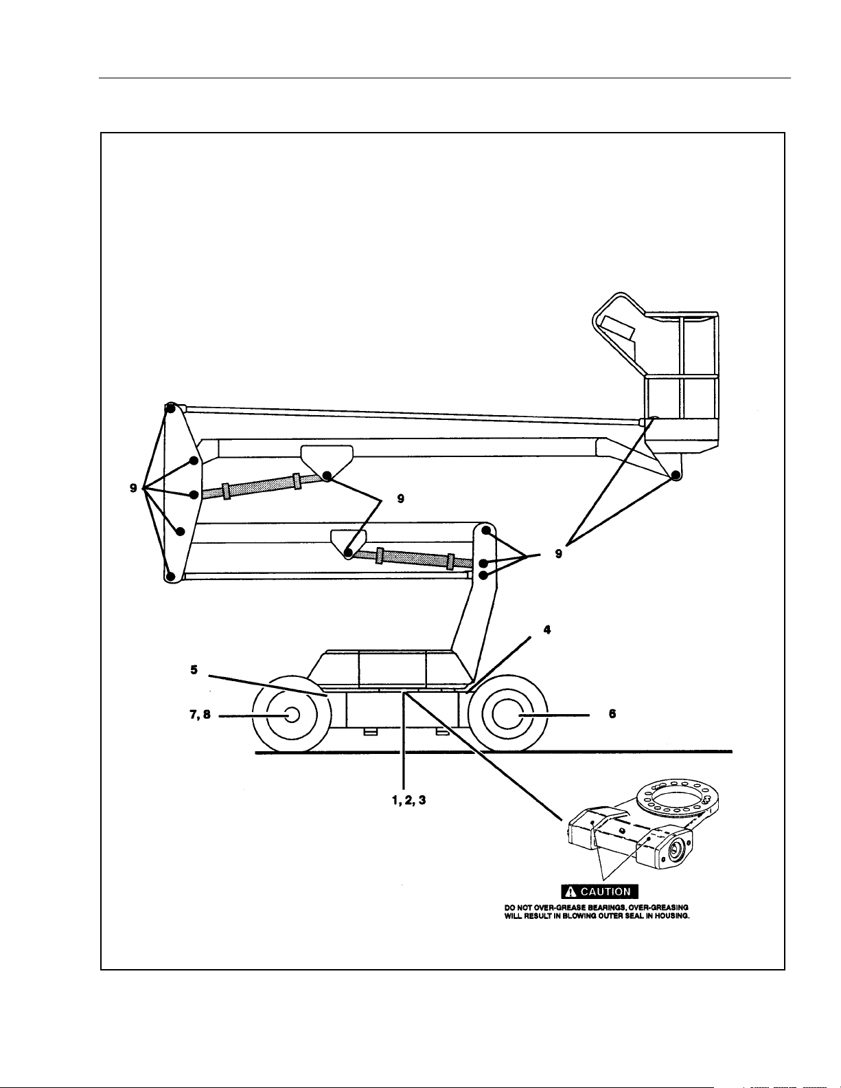
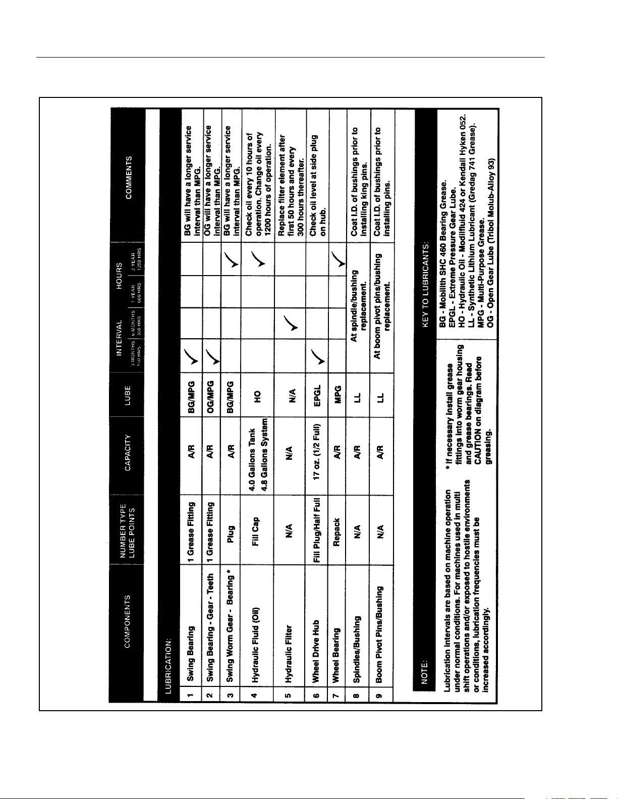
Figure 1-2. Lubrication Chart - 35/n35 electric. (Sheet 3 of 6)
SECTION 1 - SPECIFICATIONS
1-12 – JLG Lift – 3120861
Figure 1-2. Lubrication Chart - 35/n35 electric. (Sheet 4 of 6)
SECTION 1 - SPECIFICATIONS
3120861 – JLG Lift – 1-13
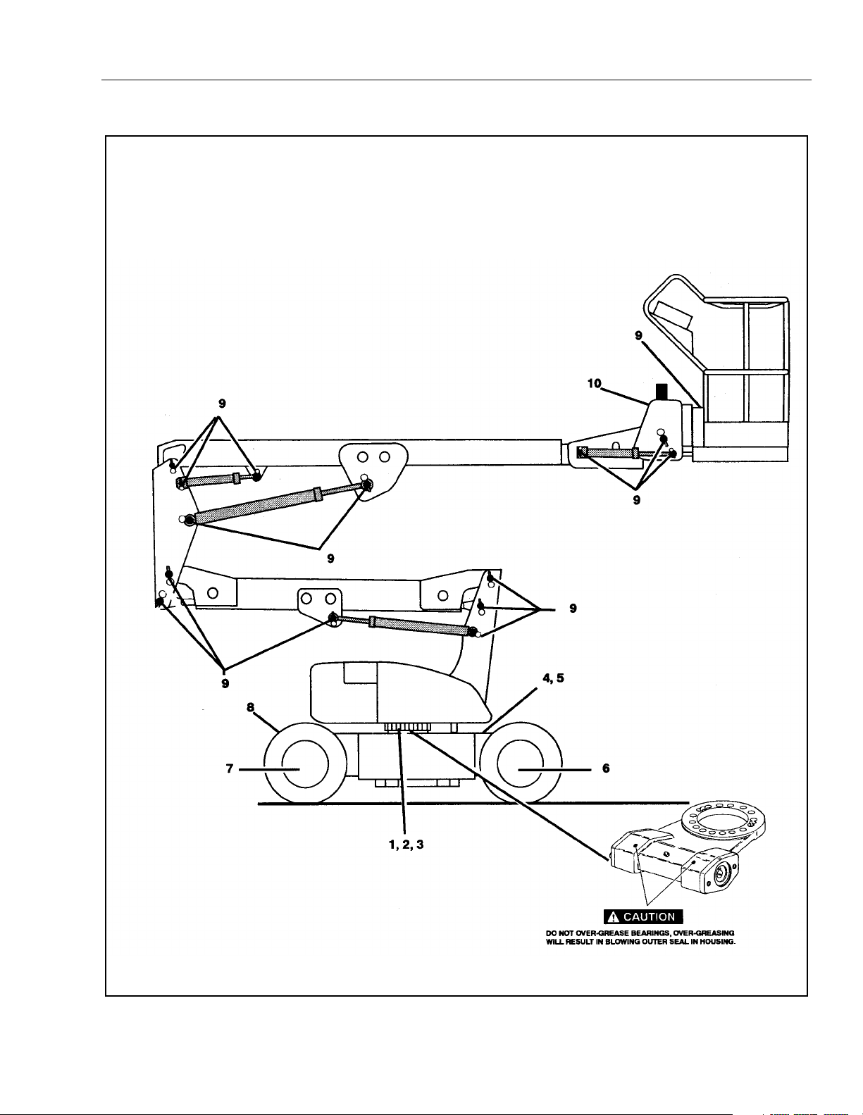
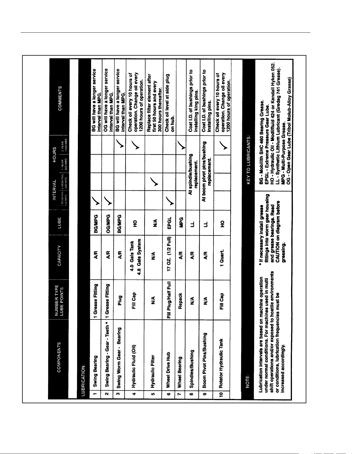
Figure 1-2. Lubrication Chart - 40/n40/45 electric. (Sheet 5 of 6)

SECTION 1 - SPECIFICATIONS
1-14 – JLG Lift – 3120861
Figure 1-2. Lubrication Chart - 40/n40/45 electric. (Sheet 6 of 6)
SECTION 1 - SPECIFICATIONS
3120861 – JLG Lift – 1-15
Figure 1-3. Serial Number Locations - 30 electric. (Sheet 1 of 3)
SECTION 1 - SPECIFICATIONS
1-16 – JLG Lift – 3120861
Figure 1-3. Serial Number Locations - 35/n35 electric. (Sheet 2 of 3)
SECTION 1 - SPECIFICATIONS
3120861 – JLG Lift – 1-17
Figure 1-3. Serial Number Locations - 40/n40/45 electric. (Sheet 3 of 3)

SECTION 1 - SPECIFICATIONS
1-18 – JLG Lift – 3120861
SECTION -
3120861 – JLG Lift – -1
SECTION 2. PROCEDURES
2.1 GENERAL.
This section provides information necessary to perform
maintenance on the aerial platform. Descriptions, tech-
niques and specific procedures are designed to provide
the safest and most efficient maintenance for use by per-
sonnel responsible for ensuring the correct installation
and operation of machine components and systems.
WHEN AN ABNORMAL CONDITION IS NOTED AND PROCEDURES
CONTAINED HEREIN DO NOT SPECIFICALLY RELATE TO THE
NOTED IRREGULARITY, WORK SHOULD BE STOPPED AND
TECHNICALLY QUALIFIED GUIDANCE OBTAINED BEFORE WORK
IS RESUMED.
The maintenance procedures included consist of servic-
ing and component removal and installation, disassembly,
and assembly, inspection, lubrication and cleaning. Infor-
mation on any special tools or test equipment is also pro-
vided where applicable.
2.2 SERVICING AND MAINTENANCE
GUIDELINES.
General.
The following information is provided to assist you in the
use and application of servicing and maintenance proce-
dures contained in this chapter.
Safety and Workmanship.
Your safety and that of others is the first consideration
when engaging in the maintenance of equipment. Always
be conscious of weight. Never attempt to move heavy
parts without the aid of a mechanical device. Do not allow
heavy objects to rest in an unstable position. When raising
a portion of the equipment, ensure that adequate support
is provided.
Cleanliness.
1. The most important single item in preserving the
long service life of a machine is to keep dirt and for-
eign materials out of the vital components. Precau-
tions have been taken to safeguard against this.
Shields, covers, seals and filters are provided to
keep oil supplies clean; however, these items must
be maintained on a scheduled basis in order to func-
tion properly.
2. At any time when hydraulic oil lines are discon-
nected, clear adjacent areas as well as the openings
and fittings themselves. As soon as a line or compo-
nent is disconnected, cap or cover all openings to
prevent entry of foreign matter.
3. Clean and inspect all parts during servicing or main-
tenance, and assure that all passages and openings
are unobstructed. Cover all parts to keep them
clean. Be sure all parts are clean before they are
installed. New parts should remain in their contain-
ers until they are ready to be used.
Component Removal and Installation.
1. Use adjustable lifting devices, whenever possible, if
mechanical assistance is required. All slings (chains,
cables, etc.) should be parallel to each other and as
near perpendicular as possible to top of part being
lifted.
2. Should it be necessary to remove a component on
an angle, keep in mind that the capacity of an eye-
bolt or similar bracket lessens, as the angle between
the supporting structure and the component
becomes less than 90 degrees.
3. If a part resists removal, check to see whether all
nuts, bolts, cables, brackets, wiring, etc. have been
removed and that no adjacent parts are interfering.
Component Disassembly and Reassembly.
When disassembling or reassembling a component, com-
plete the procedural steps in sequence. Do not partially
disassemble or assemble one part, then start on another.
Always recheck your work to assure that nothing has been
overlooked. Do not make any adjustments, other than
those recommended, without obtaining proper approval.
Pressure Fit Parts.
When assembling pressure fit parts, use an “anti-seize” or
molybdenum disulfide base compound to lubricate the
mating surface.
Bearings.
1. When a bearing is removed, cover it to keep out dirt
and abrasives. Clean bearings in nonflammable
cleaning solvent and allow to drip dry. Compressed
air can be used but do not spin the bearing.
2. Discard bearings if the races and balls (or rollers)
are pitted, scored or burned.
3. If bearing is found to be serviceable, apply a light
coat of oil and wrap it in clean (waxed) paper. Do not
unwrap reusable or new bearings until they are
ready to be installed.

SECTION -
-2 – JLG Lift – 3120861
4. Lubricate new or used serviceable bearings before
installation. When pressing a bearing into a retainer
or bore, apply pressure to the outer race. If the bear-
ing is to be installed on a shaft, apply pressure to the
inner race.
Gaskets.
Check that holes in gaskets align with openings in the
mating parts. If it becomes necessary to hand fabricate a
gasket, use gasket material or stock of equivalent material
and thickness. Be sure to cut holes in the right location as
blank gaskets can cause serious system damage.
Bolt Usage and Torque Application.
1. Use bolts of proper length. A bolt which is too long
will bottom before the head is tight against its related
part. If a bolt is too short, there will not be enough
thread area to engage and hold the part properly.
When replacing bolts, use only those having the
same specifications of the original, or one which is
equivalent.
2. Unless specific torque requirements are given within
the text, standard torque values should be used on
heat treated bolts, studs and steel nuts, in accor-
dance with recommended shop practices (See Fig-
ure 1-1).
Hydraulic Lines and Electrical Wiring.
Clearly mark or tag hydraulic lines and electrical wiring, as
well as their receptacles, when disconnecting or removing
them from the unit. This will assure that they are correctly
reinstalled.
Hydraulic System.
1. Keep the system clean. If evidence of metal or rub-
ber particles are found in the hydraulic system, drain
and flush the entire system.
2. Disassemble and reassemble parts on clean work
surface. Clean all metal parts with non-flammable
cleaning solvent. Lubricate components, as
required, to aid assembly.
Lubrication.
Service applicable components with the amount, type,
and grade of lubricant recommended in this manual, at
the specified interval. When recommended lubricants are
not available, consult your local supplier for an equivalent
that meets or exceeds the specifications listed.
Batteries.
Clean batteries using a non-metallic brush and a solution
of baking soda and water. Rinse with clean water. After
cleaning, thoroughly dry batteries and coat terminals with
an anti-corrosion compound.
Lubrication and Servicing.
Components and assemblies requiring lubrication and
servicing are shown in Lubrication Chart.
2.3 LUBRICATION INFORMATION.
Hydraulic System.
1. The primary enemy of a hydraulic system is contam-
ination. Contaminants enter the system by various
means, e.g.; inadequate hydraulic oil, allowing mois-
ture, grease, filings, sealing components, sand, etc.
to enter when performing maintenance, or by per-
mitting the pump to cavitate due to insufficient sys-
tem warm-up.
2. The design and manufacturing tolerances of the
component working parts are very close, therefore,
even the smallest amount of dirt or foreign matter
entering a system can cause wear or damage to the
components and generally results in faulty opera-
tion. Every precaution must be taken to keep
hydraulic oil clean, including reserve oil in storage.
Hydraulic system filters should be checked,
cleaned, and/or replaced at the specified intervals
required in Figure 1-2. Always examine filters for evi-
dence of metal particles.
3. Cloudy oils indicate a high moisture content which
permits organic growth, resulting in oxidation or cor-
rosion. If this condition occurs, the system must be
drained, flushed, and refilled with clean oil.
4. It is not advisable to mix oils of different brands or
types, as they may not contain the same required
additives or be of comparable viscosities. Good
grade mineral oils, with viscosities suited to the
ambient temperatures in which the machine is oper-
ating, are recommended for use.
NOTE: Metal particles may appear in the oil or filters of new
machines due to the wear-in of meshing compo-
nents.
Hydraulic Oil.
1. Refer to Table 1-1 for recommendations for viscosity
ranges.

SECTION -
3120861 – JLG Lift – -3
2. JLG recommends Mobilfluid 424 Hydraulic Oil,
which has an SAE viscosity of 10W-30 and a viscos-
ity index of 152.
NOTE: Start-up of hydraulic system with oil temperatures
below -15 degrees F. is not recommended. If it is
necessary to start the system in a sub-zero environ-
ment, it will be necessary to heat the oil with a low
density 100VAC heater to a minimum temperature of
-15 degrees F.
3. The only exception to the above is to drain and fill
the system with Mobil DTE11 oil or its equivalent.
This will allow start up at temperatures down to -20
degrees F. However, use of this oil will give poor per-
formance at temperatures above 120 degrees F.
Systems using DTE11 oil should not be operated at
temperatures above 200 degrees F. under any con-
dition.
Changing Hydraulic Oil.
1. Use of any of the recommended hydraulic oils elimi-
nates the need for changing the oil on a regular
basis. However, filter elements must be changed
after the first 50 hours of operation and every 300
hours thereafter. If it is necessary to change the oil,
use only those oils meeting or exceeding the specifi-
cations appearing in this manual. If unable to obtain
the same type of oil supplied with the machine, con-
sult local supplier for assistance in selecting the
proper equivalent. Avoid mixing petroleum and syn-
thetic base oils. JLG Industries recommends chang-
ing the hydraulic oil every two years.
2. Use every precaution to keep the hydraulic oil clean.
If the oil must be poured from the original container
into another, be sure to clean all possible contami-
nants from the service container. Always clean the
mesh element of the filter and replace the cartridge
any time the system oil is changed.
3. While the unit is shut down, a good preventive main-
tenance measure is to make a thorough inspection
of all hydraulic components, lines, fittings, etc., as
well as a functional check of each system, before
placing the machine back in service.
Lubrication Specifications
Specified lubricants, as recommended by the component
manufacturers, are always the best choice, however,
multi-purpose greases usually have the qualities which
meet a variety of single purpose requirements. Should
any question arise regarding the use of greases in mainte-
nance stock, consult your local supplier for evaluation.
Refer to Table 1-2 for an explanation of the lubricant key
designations appearing in the Lubrication Chart.
2.4 CYLINDERS - THEORY OF OPERATION.
Systems Incorporating Double Acting
Cylinders.
30 electric - Upper Boom Lift, Lower Boom Lift, and
Steer.
35/n35 electric - Upper Boom Lift, Lower Boom Lift,
Telescope, Slave, Master, Rotator, and Steer.
40/n40/45 electric - Upper Boom Lift, Mid Boom Lift,
Lower Boom Lift, Telescope, Slave, Master, Rotator,
and Steer.
A double acting cylinder is one that requires oil flow to
operate the cylinder rod in both directions. Directing oil
(by actuating the corresponding control valve to the pis-
ton side of the cylinder) forces the piston to travel toward
the rod end of the barrel, extending the cylinder rod (pis-
ton attached to rod). When the oil flow is stopped, move-
ment of the rod will stop. By directing oil to the rod side of
the cylinder, the piston will be forced in the opposite direc-
tion and the cylinder rod will retract.
Holding valves are used in the Lift circuits to prevent
retraction of the cylinder rod should a hydraulic line rup-
ture or leak develop between the cylinder and its related
control valve.
2.5 VALVES - THEORY OF OPERATION.
Control Valves.
30 electric - Control Valve 4640725 this valve controls
Swing, Lower Lift, and Upper Lift.
35/n35 electric - Control Valve 4640843 this valve con-
trols Platform, Telescope, Swing, Lower Lift, and Upper
Lift.
40/n40/45 electric - Control Valve 4640797 this valve
controls Platform, Telescope, Swing, Lower Lift, and
Upper Lift.
It consists of cartridge type valves in an anodized alumi-
num manifold. The cartridge valves provide for control of
flow, volume of flow and pressure in the hydraulic system.
The directional control valves are solenoid operated, three
position, 4-way sliding spool type valves. One valve is pro-
vided for each of the three functions. Energizing one of
the electrical coils on a valve will divert the supply of
hydraulic oil to provide motion of that function in one
direction. Energizing the other coil will divert the oil for
motion in the other direction. When neither coil is ener-
gized, the supply of hydraulic oil is blocked.
Flow control valves in the lift circuits provide for control of
the rate of flow when the oil is flowing out of the cap ends
of the cylinders (the load is being lowered). An adjusting
screw on each cartridge flow control valve allows the rate
of flow (speed) to be adjusted. When oil is flowing into the
cap end of the lift cylinders, an internal check valve feature
allows unrestricted flow.

SECTION -
-4 – JLG Lift – 3120861
Pressure relief valves limit the pressure in the swing circuit
and the rod end of each lift cylinder. When the pressure in
one of those circuits reaches the set point of the valve, the
valve opens, allowing enough flow to return to the reser-
voir so that the set pressure is not exceeded. An adjusting
screw on each cartridge relief valve allows the set pres-
sure to be adjusted.
The aluminum manifold provides the passages through
which the hydraulic oil is diverted to provide the desired
movement of the actuators. No moving parts of the valves
slide against the manifold and so it is not subject to wear.
Steer Valve 4640726.
(30/35/n35/40/n40/45 electric)
This valve controls the STEER function. It consists of
screw-in cartridge type valves in an anodized aluminum
manifold. The cartridge valves provide for control of direc-
tion of flow and pressure in the STEER hydraulic circuit.
The directional control valve is a solenoid operated, three
position, 4-way sliding spool type valve. Energizing one of
the electrical coils on the valve will divert the supply of
hydraulic oil to provide steering in one direction. Energiz-
ing the other coil will divert the oil for steering in the other
direction. When neither coil is energized, the supply of
hydraulic oil is blocked.
A pressure relief valve limits the pressure in the steer cir-
cuit. When the pressure reaches the set point of the valve,
the valve opens, allowing enough flow to return to the res-
ervoir so that pressure is not exceeded. An adjusting
screw on the cartridge relief valve allows the set pressure
to be adjusted.
The aluminum manifold provides the passages through
which hydraulic oil is diverted to provide the desired
movement of the steer cylinder. No moving parts of the
valves slide against the manifold and so it is not subject to
any wear.
2.6 MOTOR CONTROLLER.
Modes of Operation.
1. Traction Motor Drive.
a. Drive in either forward or reverse will start only if
the following conditions are satisfied:
1. Function switches off.
2. No procedure or diagnostic faults present.
3. FWD or REV selected as appropriate.
b. Once in “drive” mode, activating a function
switch shall not cause drive mode to be exited,
the pump/traction contactor drive shall not be
energized (shall be left at the traction position). If
a function switch is selected during traction, a
procedure fault will occur when neutral is
selected, remaining until a function switch and
both directions are no longer selected.
c. When neutral is selected, the controller will con-
trol smooth stopping of the machine, using plug
braking, before the electric brake is allowed to
operate.
d. If a function switch is activated in neutral, when
the vehicle has stopped and the brake is
applied, then pump mode will become opera-
tional.
1. Pump Motor Drive.
a. Pump motor drive will start only if the following
conditions are satisfied:
1. FWD and REV switch off.
2. Traction mode off (brake applied).
a. Pump drive shall only be enabled when the
direction selector inputs are in neutral and the
machine is stationary. Once pump drive mode
has been entered, then the status of the direc-
tion selector inputs shall no longer interlock
pump operation. If a direction switch is selected
during pump drive, a procedure fault will occur
when the function switch is no longer selected,
remaining until both directions and the function
switch are no longer selected.
Features.
1. Features in Traction Mode.
a. Maximum Speed Control.
The controller incorporates a function to limit the maxi-
mum speed of the machine to a percentage of maximum
possible speed. The function operates in such a manner
as to control vehicle speed by limiting the percentage on
of the switching device to keep the machine speed below
the maximum permitted value or, if required, to apply vari-
able plug braking to restrict machine speed when travel-
ing down a grade. The speed is controlled based on the
percentage of accelerator input.
1. Features in Pump Mode.
a. Proportional Control of Pump Motor Speed.
The pump motor speed shall be controlled by
varying the percentage on of the switching ele-
ment in relation to a separate pump accelerator
input.
b. Soft Start.
The pump motor speed control incorporates a
“soft start” facility by applying acceleration delay
to changes in the applied percentage on of the
switching element.
Loading...