


45e
Operators and Safety Manual
Model
30e
35e
n35e
40e
n40e
45e
3120742
August 14, 2001
ANSI
– JLG Lift –

FOREWORD
3120742 – JLG Lift – d
FOREWORD
This manual is a ve ry important tool! Keep it with the machine at all times.
The purpose of this manual is to provide owners, users, operators, lessors, and lessees with the precautions
and operating procedures essential for the safe and proper machine operation for its intended purpose. It is
important to st ress p rope r mac hine u sage at all t imes. All infor matio n in this m anu al must be re ad and under -
stood before any attempt is made to operate the machine.
Because the manufacturer has no direct control over machine operation and application, proper safety prac-
tices are the resp onsibility of the owner s, users, operators, lessors, and lessees.
All instructions in this manual are based upon the use of the machine under proper operating conditions, with
no deviations from the original design. Any alteration or modification of the machine is strictly forbidden without
written approval from JLG Industries, Inc.
Due to continu ous p rod uct im provm ents , JLG Indu stries , In c. re serv es th e rig ht to make specif icat ion c hange s
without prior notification. Contact JLG Industries, Inc. for updated information.

FOREWORD
e – JLG Lift – 3120742
SAFETY ALERT SYMBOLS AND SAFETY SIGNAL WOR DS
This is the Safety Alert Symbol. It is used to alert you to the
potential personal injury hazards. Obey all safety messages
that follow this symbol to avoid possible injury or death
The Safety Alert Symbol will be used with the appropriate Safety Signal Word of “DANGER” “WARNING” or “CAUTION” to
a potential hazard and designate a level of seri ousness. The Safety Signal Words are insert ed throughout this manual in
Black/White. On the machine, the Safety Signal Words will have either a Red, Orange, or Yellow background as part of a
safety sign or decal. The “DANGER”, “WARNING”, and “CAUTION” Safety Signal Words, definitions, and associated colors
are as follows:
Indicates an imminently hazardous situation which, if not
avoided, will
result in serious injury or death. This signal
word is used in the most extreme cases. When installed on
the machine, this Signal Word will have a Red background
as part of a decal.
Indicates a potentiality hazardous situation which, if not
avoided, could
result in serious injury or death. When
installed on the machine, this Signal Word will have an
Orange background as part of a decal.
Indicates a potentiality hazardous situation which if not
avoided, may
result in minor or moderate injury. It may also
be used to alert against unsafe practices. When installed on
the machine, this Signal Word will have a Yellow background
as part of a decal.
The “IMPORTANT” Safety Signal Word may also appear in this manual or on the machine. This Safety Signal Word
typically will not appear with the Safety Alert Symbol, but contains important information that must be followed for
safe and proper operation, The “IMPORTANT” Safety Signal Word definition and associat ed co lor is as follows.
Indicates procedures esse ntial for s afe operation and w hich,
if not followed, may result in a machine malfunctioned dam-
age. When installed in a machine, this Si gn al W ord will ha ve a
Green backgroun d as part of a decal.
FOREWORD
3120742 – JLG Lift – f
FOR:
•Accident Reporting
•Product Safety Publications
•Current Owner Updates
•Questions Regarding Product Safety
•Standards and Regulations Compliance Information
•Questions Regarding Special Product Applications
•Questions Regarding Product Modi fications
CONTACT:
Product Safety and Reliability Department
JLG Industries, Inc.
1 JLG Drive
McConnellsburg, PA 17233
Toll Free: 877-JLG-SAFE
877-554-7233
E-mail: ProductSafety@JLG.com
ALL SAFETY-RELATED BULLETINS MUST BE ACCOMPLISHED ON THIS PRODUCT. JLG INDUSTRIES, INC. MAY HAVE ISSUED SAFETY-
RELATED BULLETINS FOR THIS JLG PRODUCT. CONTACT JLG INDUSTRIE S, INC. OR THE LOCAL AUTHORIZED JLG DEA LER FOR
INFORMATION REGARDING SAFETY-RELATED BULLETINS WHICH MAY HAVE BEEN ISSUED FOR THIS PRODUCT.
FOR THE PURPOSE OF RECEIVING SAFETY-RELATED BULLETINS, IT IS IMPORTANT THAT THE CURRENT OWNER OF THIS UNIT
ENSURES JLG INDUSTRIES, INC. HAS UPDATED OWNERSHIP INFORMATION. CONTACT JLG INDUSTRIES, INC. TO ENSURE THAT THE
CURRENT OWNER RECORDS ARE UPDATED AND ACCURATE.
JLG INDUSTRIES, INC. MUST BE NOTIFIED IMMEDIATELY IN ALL INSTANCES WHERE JLG PRODUCTS HAVE BEEN INVOLVE D IN AN
ACCIDENT INVOLVING BODILY INJURY OR DEATH OF PERSONNEL OR WHEN SUBSTANTIAL DAMAGE HAS OCCURRED TO PERSONAL
PROPERTY OR THE JLG PROD UCT
.

FOREWORD
g – JLG Lift – 3120742
REVISION LOG
September 1997 - Original Issue
August 14, 2001 Revised

3120742 – JLG Lift – i
TABLE OF CONTENTS
TABLE OF CONTENTS
SUBJECT - SECTION, PARAGRAPH PAGE NO.
SECTION - FOREWORD
SECTION 1 - SAFETY PRECAUTIONS
1.1 General . . . . . . . . . . . . . . . . . . . . . . . . . . . . . . . . . . . . . . . . . . . . . . . . . . . . . . . . . . . . . . . . . . . . . .1-1
1.2 Pre-operation. . . . . . . . . . . . . . . . . . . . . . . . . . . . . . . . . . . . . . . . . . . . . . . . . . . . . . . . . . . . . . . . . .1-1
1.3 Operation. . . . . . . . . . . . . . . . . . . . . . . . . . . . . . . . . . . . . . . . . . . . . . . . . . . . . . . . . . . . . . . . . . . . .1-2
1.4 Towing, Lifting, And Hauling. . . . . . . . . . . . . . . . . . . . . . . . . . . . . . . . . . . . . . . . . . . . . . . . . . . . . .1-5
1.5 Maintenance . . . . . . . . . . . . . . . . . . . . . . . . . . . . . . . . . . . . . . . . . . . . . . . . . . . . . . . . . . . . . . . . . .1-6
SECTION 2 - PREPARATION AND INSPECTION
2.1 GENERAL. . . . . . . . . . . . . . . . . . . . . . . . . . . . . . . . . . . . . . . . . . . . . . . . . . . . . . . . . . . . . . . . . . . . .2-1
2.2 PREPARATI O N FO R USE. . . . . . . . . . . . . . . . . . . . . . . . . . . . . . . . . . . . . . . . . . . . . . . . . . . . . . . .2 -1
2.3 DELIVERY AND FREQ U E N T I N SP ECTION. . . . . . . . . . . . . . . . . . . . . . . . . . . . . . . . . . . . . . . . . . .2-1
2.4 Daily Walk-Around Inspection. . . . . . . . . . . . . . . . . . . . . . . . . . . . . . . . . . . . . . . . . . . . . . . . . . . . .2-5
2.5 dAILY FUN CTIONAL CHECK.. . . . . . . . . . . . . . . . . . . . . . . . . . . . . . . . . . . . . . . . . . . . . . . . . . . . .2-9
2.6 TORQUE REQUIREMENTS. . . . . . . . . . . . . . . . . . . . . . . . . . . . . . . . . . . . . . . . . . . . . . . . . . . . . . .2-9
2.7 BATTERY MA I N TEN AN C E A N D CH ARGING.. . . . . . . . . . . . . . . . . . . . . . . . . . . . . . . . . . . . . . . . .2-10
SECTION 3 - USER RESPONSIBILITIES AND MACHINE CONTROLS
3.1 GENERAL. . . . . . . . . . . . . . . . . . . . . . . . . . . . . . . . . . . . . . . . . . . . . . . . . . . . . . . . . . . . . . . . . . . . .3-1
3.2 PERSONNE L TRAINING. . . . . . . . . . . . . . . . . . . . . . . . . . . . . . . . . . . . . . . . . . . . . . . . . . . . . . . . .3-1
3.3 OPERATING CHARACTERISTICS AND LIMITATIONS. . . . . . . . . . . . . . . . . . . . . . . . . . . . . . . . . .3-2
3.4 CONTROL S AND INDICATORS.. . . . . . . . . . . . . . . . . . . . . . . . . . . . . . . . . . . . . . . . . . . . . . . . . . .3-2
SECTION 4 - MACHINE OPERATION
4.1 DESCRIPTION. . . . . . . . . . . . . . . . . . . . . . . . . . . . . . . . . . . . . . . . . . . . . . . . . . . . . . . . . . . . . . . . .4-1
4.2 GENERAL. . . . . . . . . . . . . . . . . . . . . . . . . . . . . . . . . . . . . . . . . . . . . . . . . . . . . . . . . . . . . . . . . . . . .4-1
4.3 MOTOR OP ERATION.. . . . . . . . . . . . . . . . . . . . . . . . . . . . . . . . . . . . . . . . . . . . . . . . . . . . . . . . . . .4-1
4.4 TRAVELIN G ( Driv ing). . . . . . . . . . . . . . . . . . . . . . . . . . . . . . . . . . . . . . . . . . . . . . . . . . . . . . . . . . . .4-2
4.5 STEERING. . . . . . . . . . . . . . . . . . . . . . . . . . . . . . . . . . . . . . . . . . . . . . . . . . . . . . . . . . . . . . . . . . . .4-2
4.6 PLATFORM.. . . . . . . . . . . . . . . . . . . . . . . . . . . . . . . . . . . . . . . . . . . . . . . . . . . . . . . . . . . . . . . . . . .4-3
4.7 BOOM.. . . . . . . . . . . . . . . . . . . . . . . . . . . . . . . . . . . . . . . . . . . . . . . . . . . . . . . . . . . . . . . . . . . . . . .4-3
4.8 BOOM FUNCTION SPEEDS. . . . . . . . . . . . . . . . . . . . . . . . . . . . . . . . . . . . . . . . . . . . . . . . . . . . . .4-4
4.9 SHUT DOWN AND PARK.. . . . . . . . . . . . . . . . . . . . . . . . . . . . . . . . . . . . . . . . . . . . . . . . . . . . . . . .4-4
4.10 MACHINE TIE DOWN.. . . . . . . . . . . . . . . . . . . . . . . . . . . . . . . . . . . . . . . . . . . . . . . . . . . . . . . . . . .4-4
4.11 MACHINE LIFTIN G.. . . . . . . . . . . . . . . . . . . . . . . . . . . . . . . . . . . . . . . . . . . . . . . . . . . . . . . . . . . . .4-6
SECTION 5 - OPTIONAL EQUIPMENT
5.1 MOTION ALARM.. . . . . . . . . . . . . . . . . . . . . . . . . . . . . . . . . . . . . . . . . . . . . . . . . . . . . . . . . . . . . . .5-1
5.2 FOAM FILL E D TIRES. . . . . . . . . . . . . . . . . . . . . . . . . . . . . . . . . . . . . . . . . . . . . . . . . . . . . . . . . . . .5-1
5.3 NON-MA RKING TIRES.. . . . . . . . . . . . . . . . . . . . . . . . . . . . . . . . . . . . . . . . . . . . . . . . . . . . . . . . . .5-1
5.4 ROTATI N G BEACON. . . . . . . . . . . . . . . . . . . . . . . . . . . . . . . . . . . . . . . . . . . . . . . . . . . . . . . . . . . .5-1
5.5 TILT ALARM. . . . . . . . . . . . . . . . . . . . . . . . . . . . . . . . . . . . . . . . . . . . . . . . . . . . . . . . . . . . . . . . . . .5-1
5.6 WHEEL COV ERS. . . . . . . . . . . . . . . . . . . . . . . . . . . . . . . . . . . . . . . . . . . . . . . . . . . . . . . . . . . . . . .5-1
5.7 BATTERY PA CKS.. . . . . . . . . . . . . . . . . . . . . . . . . . . . . . . . . . . . . . . . . . . . . . . . . . . . . . . . . . . . . .5-1
5.8 PLATFOR M LI GH TS.. . . . . . . . . . . . . . . . . . . . . . . . . . . . . . . . . . . . . . . . . . . . . . . . . . . . . . . . . . . .5-1
5.9 Control Console Cover.. . . . . . . . . . . . . . . . . . . . . . . . . . . . . . . . . . . . . . . . . . . . . . . . . . . . . . . . . .5-1
5.10 CYLINDER BELLOW S. . . . . . . . . . . . . . . . . . . . . . . . . . . . . . . . . . . . . . . . . . . . . . . . . . . . . . . . . . .5-1
5.11 STEEL HOOD COVERS. ( 30 e le ctric). . . . . . . . . . . . . . . . . . . . . . . . . . . . . . . . . . . . . . . . . . . . . . .5-1
5.12 WORK PLATFORM. (35/40/n40/45 elec t r ic) . . . . . . . . . . . . . . . . . . . . . . . . . . . . . . . . . . . . . . . . . .5-1
5.13 SIMULTANEOUS DRIVE / LIFT / STEER. (n40/40/45 electric). . . . . . . . . . . . . . . . . . . . . . . . . . . .5-1

ii – JLG Lift – 3120742
TABLE OF CONTENTS (Continued)
SECTION 6 - EM ERGENCY PROCEDURES
6.1 GENERAL.. . . . . . . . . . . . . . . . . . . . . . . . . . . . . . . . . . . . . . . . . . . . . . . . . . . . . . . . . . . . . . . . . . . .6-1
6.2 EMERGENCY TOWING PROCEDURES . . . . . . . . . . . . . . . . . . . . . . . . . . . . . . . . . . . . . . . . . . . . .6-1
6.3 EMERGENCY CONTR OLS AND THEIR LOCATIONS.. . . . . . . . . . . . . . . . . . . . . . . . . . . . . . . . . . 6 -1
6.4 EMERGENCY OPER AT ION. . . . . . . . . . . . . . . . . . . . . . . . . . . . . . . . . . . . . . . . . . . . . . . . . . . . . . .6-2
6.5 INCIDENT NOTIF I CA TION. . . . . . . . . . . . . . . . . . . . . . . . . . . . . . . . . . . . . . . . . . . . . . . . . . . . . . . .6-2
SECTION 7 - INSPECTION AND REPAIR LOG
LIST OF FIGURES
LIST OF FIGURES
FIGURE NO. TITLE PAGE NO.
2-1. Boom Nomenclature. (30/35/n35 electric) . . . . . . . . . . . . . . . . . . . . . . . . . . . . . . . . . . . . . . . . . . .2-3
2-2. Boom Nomenclature. (40/n45/45electric). . . . . . . . . . . . . . . . . . . . . . . . . . . . . . . . . . . . . . . . . . . .2-4
2-3. Daily walk-around Inspect ion. (Sheet 1 of 3) . . . . . . . . . . . . . . . . . . . . . . . . . . . . . . . . . . . . . . . . .2-6
2-4. Lubri cation Chart - 30 electri c. (Sheet 1 of 6). . . . . . . . . . . . . . . . . . . . . . . . . . . . . . . . . . . . . . . . .2-11
2-4. lubri cation Chart - 30 electric. (Sheet 2 of 6) . . . . . . . . . . . . . . . . . . . . . . . . . . . . . . . . . . . . . . . . .2-12
2-4. Lubri ca t ion Chart - 35/n35 electric. (Sheet 3 of 6) . . . . . . . . . . . . . . . . . . . . . . . . . . . . . . . . . . . . .2-13
2-4. Lubri ca t ion Chart - 35/n35 electric. (Sheet 4 of 6) . . . . . . . . . . . . . . . . . . . . . . . . . . . . . . . . . . . . .2-14
2-4. Lubri cation Chart - 40/n40/45 ele ct r ic. (Sheet 5 of 6). . . . . . . . . . . . . . . . . . . . . . . . . . . . . . . . . . .2-15
2-5. Torque Chart. . . . . . . . . . . . . . . . . . . . . . . . . . . . . . . . . . . . . . . . . . . . . . . . . . . . . . . . . . . . . . . . . .2-17
3-1. Position of Least Forward Stability, 30 electric. (Sheet 1 of 3) . . . . . . . . . . . . . . . . . . . . . . . . . . .3-3
3-1. Position of Least Fo rward Stability, 35/n3 5 el e ctric. (Sheet 2 of 3). . . . . . . . . . . . . . . . . . . . . . . .3-4
3-1. Position of Least Forward Stability, 40/n40/45 electric. (Sheet 3 of 3) . . . . . . . . . . . . . . . . . . . . .3-5
3-2. Position of Least Bac kward Stability, 30 e l e c t r ic . (S he e t 1 of 3). . . . . . . . . . . . . . . . . . . . . . . . . .3-6
3-2. Positio n of Least Backward Stability, 35/n35 electr ic. (Sheet 2 of 3) . . . . . . . . . . . . . . . . . . . . . .3-7
3-2. Positio n of Le a s t Ba ck ward Stability, 40/n40/45 electric. (Sheet 3 of 3). . . . . . . . . . . . . . . . . . . .3-8
3-3. Ground Control Station, 30 ele ct r ic. (Sheet 1 0f 4). . . . . . . . . . . . . . . . . . . . . . . . . . . . . . . . . . . . .3-9
3-4. Platform Control Consol e .. . . . . . . . . . . . . . . . . . . . . . . . . . . . . . . . . . . . . . . . . . . . . . . . . . . . . . . 3-13
4-1. Grade a nd Side Slopes. . . . . . . . . . . . . . . . . . . . . . . . . . . . . . . . . . . . . . . . . . . . . . . . . . . . . . . . . .4 -3
4-2. Upright Positioning Models 40e and 45e.. . . . . . . . . . . . . . . . . . . . . . . . . . . . . . . . . . . . . . . . . . . .4-5
4-3. Chassis & Platform Tie Down. (All Models) . . . . . . . . . . . . . . . . . . . . . . . . . . . . . . . . . . . . . . . . . .4-7
4-4. Lifting Chart. . . . . . . . . . . . . . . . . . . . . . . . . . . . . . . . . . . . . . . . . . . . . . . . . . . . . . . . . . . . . . . . . . .4-8
LIST OF TABLES
LIST OF TABLES
TABLE NO. TITLE PAGE NO.
1-1 Minimum Safe Approach Dist ances (M.S.A.D.) . . . . . . . . . . . . . . . . . . . . . . . . . . . . . . . . . . . . . . .1-4
7-1 Inspection and Repair Log . . . . . . . . . . . . . . . . . . . . . . . . . . . . . . . . . . . . . . . . . . . . . . . . . . . . . . .3

SECTION 1 - SAFETY PRECAUTIONS
3120742 – JLG Lift – 1-1
SECTION 1. SAFETY PRECAUTIONS
1.1 GENERAL
This section outlines the necessary precautions for proper
and safe machine usage and maintena nce. In order to
promote proper machine usage, it is mandatory that a
daily routine is established based on the content of this
manual. A maintenance program, using the information
provided in this manual and the Service and Maintenance
Manual, must also be established by a qualified person
and must be followed to ensure that the machine is safe to
operate.
The owner/user/operator/lessor/lessee of the machine
should not accept operating responsibility until t his man-
ual has been read, training is accomplished, and opera-
tion of the machine has been completed under the
supervision of an experienced and qualified operator.
The owner/user/operator/lessor/l essee must be familiar
with Sections 6, 7, 8, 9, 10 of ANSI A92.5-1992. These
sections contain the responsibilities of the owner, user,
operator, lessor, and lessee concerning safety, training,
inspection, maintenance, application, and operation.
If there are any questions with regard to safety, training,
inspection, maintenance, application, and operation,
please contact JLG Industries, Inc. (“JLG”).
FAILURE TO COMPLY WITH TH E SAFETY PRE CAUTIONS LIS TED
IN THIS MANUAL COULD RESULT IN MACHINE DAMAGE, PROP-
ERTY DAMAGE, PERSONAL INJURY OR DEATH.
1.2 PRE-OPERATION
Operator Training and Knowledge
• The Operators and Safety Manual must be read and
understood entirety before operating the mach in e. For
clarification, questions, or additional information
regarding any portions of this manual, contact JLG
Industries, Inc.
• An operator must not a ccept operating resp onsibilities
until adequate training has been given by competent
and authorized persons.
• Allow only those authorized and qualified personnel to
operate the machine who have demonstrated that they
understand the safe and proper operation and mainte-
nance of the unit.
• Read, understand, and obey all DANGERS, WARN-
INGS, CAUTIONS, and operating instructions on the
machine and in thi s manual.
• Ensure that the machine is to be used in a manner
which is within the scope of its intended application as
determined by JLG.
• All operating personnel must be familiar with the emer-
gency controls and emergency operation of the
machine as specif ied in this manual.
• Read, understand, and obey all applicable employer,
local, and governmental regulations as they pertain to
your utilization and applic ation of the machine.
Workplace Inspection
• Precautions to avoid all hazards in the work area must
be taken by the user before operation of the machine.
• Do not operate or raise the platform from a position on
trucks, trailers, railway c ars, floa ting vessels , scaffolds
or other equipment unless the application is approved
in writing by JLG.
• Before operation, check work area for overhead haz-
ards such as electric lines, bri dge cranes, and o ther
potential overhead obstructions.
• Check floor surfaces for holes, bumps, drop-offs,
obstructions, debris, concealed holes, and other
potential hazards.
• Check the work area for hazardous locations. Do not
operate the machine in hazardous environments
unless approved for that purpose by JLG.
• Ensure that the ground conditions are adequate to
support the maximum tire load indicated on the tire
load decals located on the chassis adjacent to each
wheel.
• Do not operate the machine when wind conditions
exceed 30 mph (12.5 m/s).
• This machine can be operated in nominal ambient tem-
peratures of 0
o
F to 104
o
F (-20
o
C to 40
o
C). Consult
JLG to optimize operation outsid e of this t emperature
range.

SECTION 1 - SAFETY PRECAUTIONS
1-2 – JLG Lift – 3120742
Machine Inspection
• Do not operate this machine until the inspections and
functional checks have been performed as specified in
the Preparation and Inspection section of this manual.
• Do not operate this machine until it has been serviced
and maintained according to the maintenance and
inspection requirements as specified in the machine’s
Service and Maintenance Manual.
• Ensure the footswitch and all other safety devices are
operating properly. Modification of these devices is a
safety violation.
MODIFICATIO N OR ALT ERATION OF AN AERI AL WORK P LAT-
FORM SHALL BE MADE ONLY WITH PRIOR WRITTEN PERMIS-
SION FROM THE MANUFACTURER
• Do not operate any machine on which the safety or
instruction pla ca r ds or de c al s are missing or illegible.
• Check the machine for modifications to original com-
ponents. Ensure that any modifications have been
approved by JLG.
• Avoid accumulation of debris on platform floor. Keep
mud, oil, grease, and other slippery sub stances fro m
footwear and platform deck.
1.3 OPERATION
General
• Do not use the machine for any purpose other than
positioning per sonnel, their tool s, and equipment.
• Before operation, the user must be familiar with the
machine capabilities and operating characteristics of
all functions. (Ref. Table 4-1 Machine Operation.)
• Never operate a malfunctioning machine. If a malfunc-
tions occurs, shut down the machine. Remove the unit
from service and notify the proper authorities.
• Do not remove, modi fy, or disable the foots wit ch or a ny
other safety devices.
• Never slam a control switch or lever through neutral to
an opposite direction. Always return switch to neutral
and stop before moving the switch to the next function.
Operate controls with slow and even pressure.
• Hydraulic cylinders should never be left at end of travel
(fully extended or fully retracted) before shutdown or
for long periods of time. Always “bump” control in
opposite direction s lightly wh en fu nction re aches end
of travel. This applies both to machines in operation or
in the stowed position.
• Do not allow personnel to tamper with or operate the
machine from the gro und with pe rsonnel in t he plat-
form, except in an emergency.
• Do not carry materials directly on platform railing
unless approved by JLG.
• When two or more persons are in the platform, the
operator shall be responsible for all machine opera-
tions.
• Always ensure that power tools are properly stowed
and never left hanging by their cord from the platform
work area.
• When driving, always position boom over rear axle in
line with the direction of travel. Remember, if boom is
over the front axle, the direction of steer and drive will
be opposite from normal operation.
• Do not assist a stuck or disabled machine by pushing,
pulling, or by using boom functions. Assist only by
pulling at the chassis tie-down lugs.
• Do not place boom or platform agains t any s tructure to
steady the platform or to support the structure.
• Stow boom and shut off all power before leaving
machine.
SECTION 1 - SAFETY PRECAUTIONS
3120742 – JLG Lift – 1-3
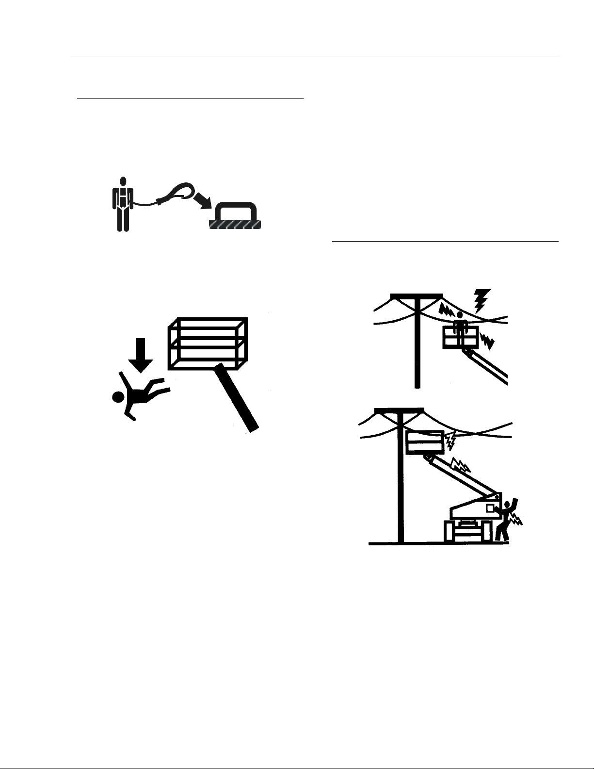
Trip and Fall Hazards
JLG Industries, Inc. requires that all persons in the plat-
form wear a full body harness with a lanyard attached to
an authorized lany ard anchorage point while oper ating
this machine. For further information regarding fall protec-
tion requirements on JLG products, contact JL G Indus-
tries, Inc.
• Prior to operation, ensure all gates are fastened and
secured in their proper position. Identify the desig-
nated lanyard anchorage point(s) at the platform and
securely attach the lanyard. Attach only one (1) lan-
yard per lanyard anchorage point.
• Keep both feet firmly positioned on the platform floor at
all times. Never position ladders, boxes, steps, planks,
or similar items on unit to pro vide additional reach for
any purpose.
• Never use the boom assembly to gain access to or
leave the platform.
• Use extreme caution when entering or leaving plat-
form. Ensure that the boom is fully lowered. Face the
machine when entering or leaving the platform.
Always maintain “three point contact” with the
machine, using two hands and one foot or two feet and
one hand at all times during entry and exit.
• Platform-to-structure transfers at elevated positions are
discouraged. Where transfer is necessary, enter/exit
through the gate only with the platform within 1 foot
(0.3m) of a safe and secure structure. 100% tie-off is
also required in this situation utilizing two lanyards.
One lanyard must be attached to the platform with the
second lanyard attached to the structure. The lanyard
connected to the platform must not be disconnected
until such time the t ransfe r to the st ructure i s safe and
complete.
• Keep oil, mud, and slippery substances cleaned from
footwear and the platform floor.
Electrocution Hazards
• This machine is not insulated and does not provide
protection from contact with an electrically charged
conductor.
• Maintain safe clearance from electrical lines, appara-
tus, or any energized (exposed or insul ated) parts in
accordance with the Minimum Safe Approach Distance
(MSAD) as specified in Table 1-1. Allow for machine
movement and electrical line swaying.
SECTION 1 - SAFETY PRECAUTIONS
1-4 – JLG Lift – 3120742
• Maintain a clearance of at least 10 ft (3m) between any
part of the machine and its occupants, their tools, and
their equipment from any ele ctrical line or ap paratus
carrying up to 50,000 volts. One foot additional clear-
ance is required for every additional 30,000 volts or
less.
DO NOT MANEUVER MACHINE OR PERSONNEL INSIDE PROHIB-
ITED ZONE (MSAD). ASSUME ALL ELECTRICAL PARTS AND
WIRING ARE ENERGIZED UNLESS KNOWN OTHERWISE.
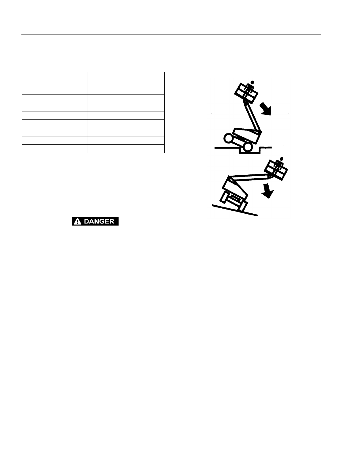
Tipping Hazards
• Ensure that the ground conditions are adequate to
support the maximum tire load indicated on th e
machine. Do not travel on unsupported surfaces.
• The user should be familiar with the driving surface
before driving. Do not exceed the allowable sideslope
and grade while driving.
• Do not elevate platform or drive with platform elevated
while on a sloping, uneven, or soft surface. Ensure
machine is positioned on a firm, level and uniformly
supported surface before elevating platform or driving
with the platform in the elevated position.
• Before driving on floors, bridges, trucks, and other sur-
faces, check allowable capacity of the surfaces.
• Never exceed the maximum work load as specified on
the platform. Distribute loads evenly on platform floor.
Keep all loads within the confines of the platform,
unless authorized by JLG.
Table 1-1.Minimum Safe Approac h Distances (M.S.A.D.)
Voltage Range
(Phase to Phase)
MINIMUM SAFE APPROACH
DISTANCE
in Feet (Meters)
0 to 300V AVOID CONTACT
Over 300V to 50 KV 10 (3)
Over 50KV to 200 KV 15 (5)
Over 200 KV to 350 KV 20 (6)
Over 350 KV to 500 KV 25 (8)
Over 500 KV to 750 KV 35 (11)
Over 750 KV to 1000 KV 45 (14)
SECTION 1 - SAFETY PRECAUTIONS
3120742 – JLG Lift – 1-5
• Keep the chassis of the machine a minimum distance
of 2 ft. (0.6m) from holes, bumps, drop-offs, obstruc-
tions, debris, concealed holes, and other potential
hazards at the ground level.
• Never push or pull the machine or other objects by
telescoping or retracting the boom.
• Never attempt to use the machine as a crane. Do not
tie-off machine to any adjacent structure. Never attach
wire, cable, or any similar items to platform.
• Do not operate the machine when wind conditions
exceed 30 mph (12.5 m/s).
• Do not cover the platform sides or carry large surface-
area items in the p latfor m when o peratin g outd oors.
The addition of such items increases the exposed win d
area of the machine.
• Do not increase the platform size with unauthorized
deck extensions or attachmen t s .
• If boom assembly or platform is caught so that one or
more wheels are off the ground, all persons must be
removed before attempting to free the machine. Use
cranes, forklift trucks, or other appropriate equipment
to stabilize mach in e and remove person ne l.
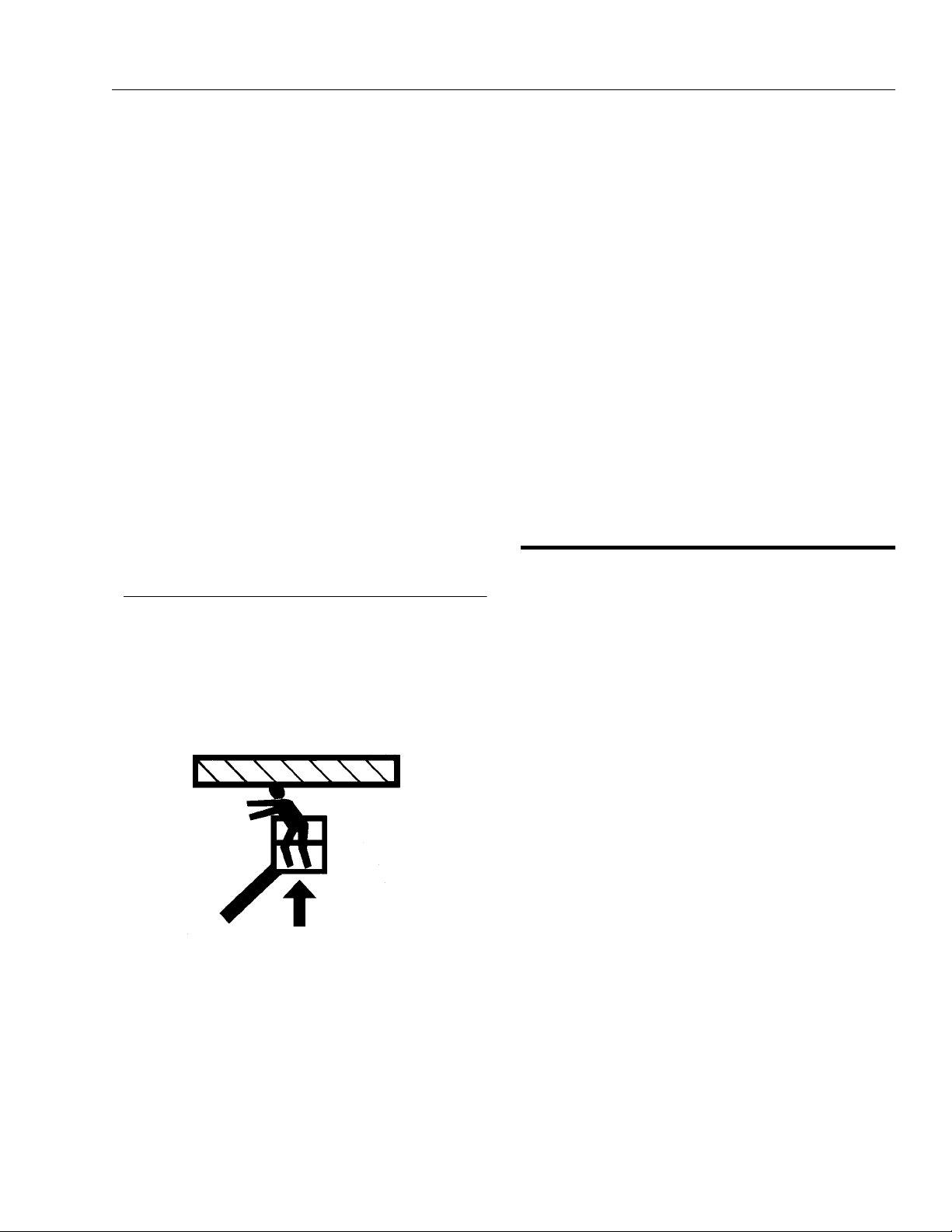
Crushing and Collision Hazards
• Approved head gear must be worn by all operating
and ground personne l.
• Keep hands and limbs away from boom assembly dur-
ing operation.
• Watch for obstructions around machine and overhead
when driving. Check clearances above, on sides, and
bottom of platform when lifting or lowering platform.
• During operation, keep all body parts inside platform
railing.
• Use the boom functions, not the drive function, to posi-
tion the platform close to obstacles.
• Always post a lookout when driving in areas where
vision is obstructed.
• Keep non-operating personnel at least 6 ft. (1.8m)
away from machine during all driving operations.
• Under all travel conditions, the operator must limit
travel speed according to conditions of ground sur-
face, congestion, visibility, slope, location of personnel,
and other factors causing hazards of collision or injury
to personnel.
• Be aware of stopping distances in all drive speeds.
When driving in high speed, switch to low speed
before stopping. Travel grades in low speed only.
• Do not use high speed drive in restricted or close quar-
ters or when dr iving in reverse.
• Exercise extreme caution at all times to prevent obsta-
cles from striking or interfering with operating controls
and persons in the pla tf orm .
• Ensure that operators of other overhead and floor level
machines are aware of the aerial work platform’s pres-
ence. Disconnect power to over head cranes. Bar ri-
cade floor area if necessary.
• Avoid operating over ground personnel. Warn person-
nel not to wo rk , sta nd, o r wa lk un der a r ai sed bo om or
platform. Position barricad e s on floor as necessary.
1.4 TOWING, LIFTING, AN D HAULING
• Never allow personnel in platform while towing, lifting,
or hauling.
• This machine should not be towed, except in the event
of emergency, malfunction, power failure, or loading/
unloading. Refer to the Emergency Procedures sec-
tion of this manual for emergency towing procedures.
• Ensure boom is in the stowed position and the turnta-
ble locked prior to towing, lifting or h auling. The plat-
form must be completely empty of tools.
• When lifting machine, lift only at designated areas of
the machine. Lift with lifting equipment of adequate
capacity.
• Refer to the Machine Operation section of this manual
for lifting information.
SECTION 1 - SAFETY PRECAUTIONS
1-6 – JLG Lift – 3120742
1.5 MAINTENANCE
General
This section co ntains general sa fety pre cautions which
must be observed during maintenance of this machine.
Additional precautions to be observed during machine
maintenance are inserted at the appropriate points in this
manual and in the Service and Maintenance Manual. It is
of utmost importance that maintenance personnel pay
strict attention to these precautions to avoid possible
injury to personnel or damage to the machine or property.
A maintenance prog ram must be establ ished by a qua li-
fied person an d must be follow ed to ensure that the
machine is safe.
Maintenance Hazards
• Shut off power to all controls and ensure that all oper-
ating systems are secured from inadvertent motion
prior to performing any adjustments or repairs.
• Never work under an elevated platform until it has been
fully lowered to the full down position, if possible, or
otherwise supported and restrain ed from movemen t
with appropriate safety props, blocking, or overhead
supports.
• Always relieve hydraulic pressure from all hydraulic cir-
cuits before loos ening o r removing hyd rauli c compo-
nents.
• Always disconnect batteries when servicing electrical
components or whe n performing weld ing on the
machine.
• Shut down the engine (if equipped) while fuel tanks are
being filled.
• Ensure replacement parts or components are identical
or equivalent to original parts or components.
• Never attempt to move heavy parts without the aid of a
mechanical device. Do not allow heavy objects to rest
in an unstable position. Ensure adequate support is
provided when raising components of the machine.
• Remove all rings , watch es, and j ewelry when pe rform -
ing any maintenance. Do not wear l oose fitt ing cloth-
ing or long hair unrestrained which may become
caught or entangled in equipment.
• Use only clean approved non-flammable cleaning sol-
vents.
• Never alter, remove, or substitute any items such as
counterweights, tires, batteries, platforms or other
items that may re duce or affe ct the over all weight or
stability of the machine. Reference the Service and
Maintenance Manual for the weights of critical stability
items.
MODIFICATI ON OR ALT ERATION O F AN AERI AL WORK P LAT-
FORM SHALL BE MADE ONLY WITH PRIOR WRITTEN PERMIS-
SION FROM THE MANUFACTURER
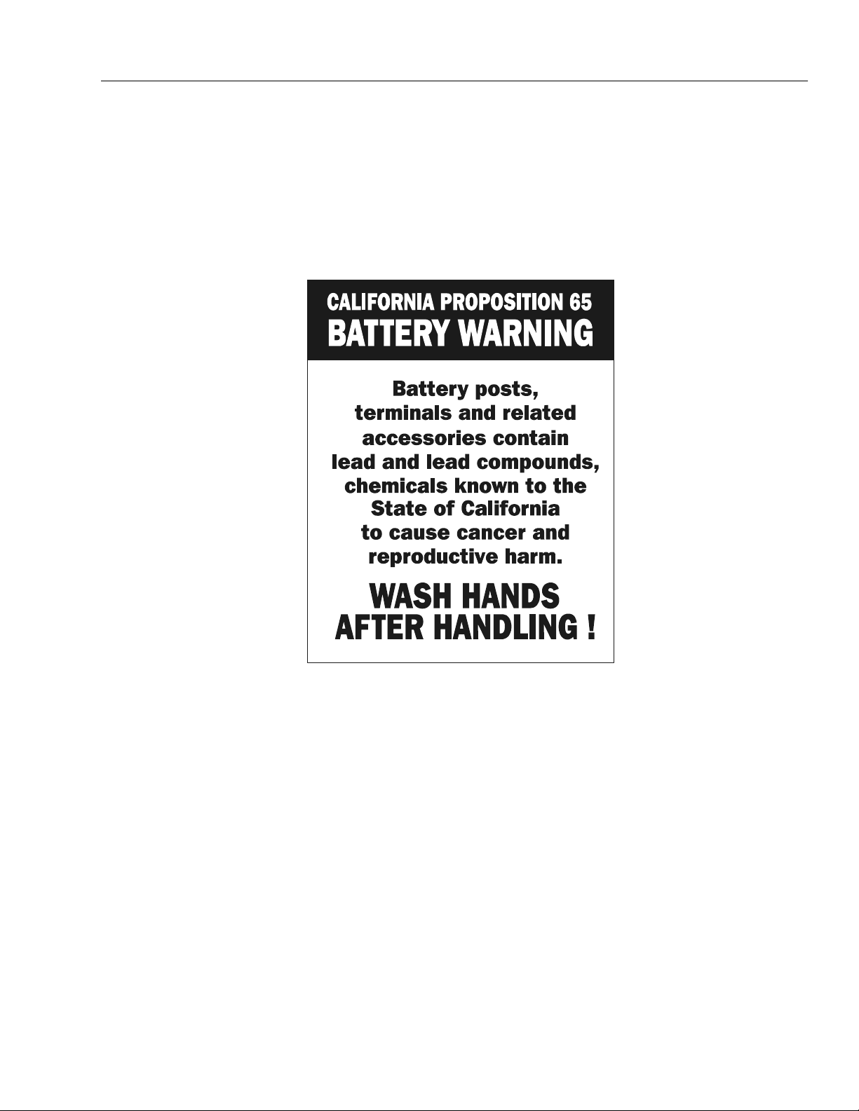
Battery Hazards
• Always disconnect batteries when servicing electrical
components or whe n performing weld ing on the
machine.
• Do not allow smoking, open flame, or sparks near bat-
tery during charging or servicing.
• Do not contact tools or other metal objects across the
battery terminals.
• Always wear hand, eye, and face protection when ser-
vicing batteries. Ensure that batte ry acid does not
come in contact wi th skin or clothing.
BATTERY FLUID IS HIGHLY CORROSIVE. AVOID CONTACT WITH
SKIN AND CLOTHING AT ALL TIMES. IMMEDIATELY RINSE ANY
CONTACTED ARE A WITH CLEAN W ATER AND SEE K MEDICAL
ATTENTION.
• Charge batteries only in a well ventilated area.
• Avoid overfilling the battery fluid level. Add distilled
water to batteries only after the batteries are fully
charged.
SECTION 2 - PREPARATION AND INSPECTION
3120742 – JLG Lift – 2-1
SECTION 2. PREPARATION AND INSPECTION
2.1 GENERAL.
This section provides the necessary information needed
by those personnel that are responsible to place the
machine in operation readiness, and lists checks that are
performed prior to use of the machine. It is important that
the information contained in this section be read and
understood before any attempt is made to operate the
machine. Ensure that all the necessary inspections have
been completed successfully before placing the m achine
into service. These procedures will aid in obtainin g maxi-
mum service life and safe oper a t ion.
SINCE THE MACHINE MANUFACTURER HAS NO DIRECT CON-
TROL OVER THE FIE LD INSPECTION AND MAINTENANC E,
SAFETY IS THE RESPONSIBILITY OF THE OWNER/OPERATOR.
2.2 PREPARATION FOR USE.
Before a new machine is put into operation it must be
carefully inspected for any evidence of damage resulting
from shipment and in specte d period ically therea fter, as
outlined in Delivery and Frequent Inspection (see section
2-3). (During initial start-up and run,) the unit should be
thoroughly checked for hydraulic l eaks. A check of all
components should be made to assure their security.
All preparation n ecessar y to pl ace the machin e in oper a-
tion readiness stat us is the respo nsibil ity of man ageme nt
personnel. Preparation requires good common sense,
(i.e. lift works smoothly and brakes operate properly) cou-
pled with a s eries of visu al ins pectio ns. The m andator y
requirements are given in the Daily Walk Around Inspec-
tion (see section 2-4).
It should be assured that the items appearing in the Deliv-
ery and Frequent Inspection and Functional Check are
complied with prior to putting the machine into service.
2.3 DELIVERY AND FREQUENT
INSPECTION.
NOTE: This machine requires periodic safety and mainte-
nance inspections by an authorized JLG Dealer. A
decal located on the frame provides a place to
record (stamp) inspection dates. Check decal and
notify dealer if inspection is overdue.
NOTE: ANSI/SIA 92.5-1992 also requires an annual inspec-
tion to be perfo rmed. See ann ual mac hine ins pectio n
report CGF330.
The following checklist provides a systematic inspection
to assist in detecting defective, damaged, or improperly
installed parts. The checklist denotes the items to be
inspected and cond it io ns t o e xam ine.
Frequent inspection shall be performed every 3 months or
150 hours whichever come first, or more often when
required by environment, severity, and frequency of
usage.
This inspection checklist is also applicable and must be
followed for all machines that have been in storage or for
all machines that have been exposed to harsh or chang-
ing climates.
These checks are also to be performed after maintenance
has been performed on the machine.
Chassis.
1. Check front tires and wheel assemblies for loose or
worn spindles, components and hardware for secu-
rity, tires for wear, damage and proper inflat ion.
2. Check front axle for loose, missing, and worn parts,
pivot pin for security.
3. Check steering assembly for loose or bent steer cyl-
inder rods, steer cylinder and hydraulic lines for
leaks and security, and hardware for proper installa-
tion.
4. Check rear tires and wheel assemblies for security,
tires for wear, damage and proper inflation.
5. Check drive hu bs fo r dama ge an d lea ks , and m ot ors
and brakes for dama ge.
6. Check oil level in drive hubs by removing ‘fill plug’
on top and ‘check p lug’ on side. Fill from to p with
EPGL SAE90 until oil flows from check plug.
Replace both plugs.
7. Check valves and hydraulic lines for damage, leak-
age and security.
8. Check pump/motor and accessories for damage,
loose or missing parts, leakage and security. Check
electrical connections for corrosion and tightness
and wiring for insulation damage. Check hydraulic
filter for condition of element. Replace as required.
9. Check hydraulic reservoir and hydraulic lines for
damage, leakage an d se curity.

SECTION 2 - PREPARATION AND INSPECTION
2-2 – JLG Lift – 3120742
10. Check batteries for damage, loose or m issing vent
caps, electrical connections for tightness and evi-
dence of corrosion, and electrolyte level. Add only
clean distilled water to battery after it has been
charged.
Turntable.
11. Check turn tabl e f or dama ge , loos e or mi ssin g part s,
and security. Check lift cylinders and hydraulic lines
for damage, leakage and security. Check swing
drive motor for damage, loose or missing parts,
hydraulic lines and component housings for evi-
dence of leakage; worm gear for proper mesh with
swing gear.
12. Check swing bearing for damage, wear, lubrication
and loose or mi ss ing bearing bolt s.
13. Check valves and hydraulic lines for damage, leak-
age, security and electrical connections for tightness
and evidence of corrosion.
14. Check ground controls for damage, loose or miss-
ing parts, security, electrical connections for tight-
ness and evidence of corrosion and wiring for
insulation damage. Assure that all switches function
properly.
NOTE: JLG recommends replacing the hydraulic filter ele-
ment after th e first 50 hours of operation and then
every 300 hours thereafter, unless operating condi-
tions require earlier replacement.
1. Check all cowl and access doors for damage,
proper operation and security.
2. Check Lower Boom pivot bushings for lubrication
and wear.
3. Check Lower Boom Lift Cylinder and hydraulic lines
for damage, leakage and security.
4. Check all pin and shaft retaining hardware for secu-
rity and wear.
5. Check all electrical cables for damage, loose and
corroded connections.
30/35/n35 electric - Boom. (See Figure 2-1)
1. Check Lower Boom and leveling link for damage,
missing parts an d security.
2. Check all pin and shaft retaining hardware for secu-
rity and wear.
3. Check hydraulic lines and electrical cable for dam-
age, missing parts and security.
4. Check limit swi tch connection s and pl unger fo r cor-
rosion and security.
5. Check limit switch connections and plunger for cor-
rosion and security.
6. Check Upright for damage, wear, lubrication, and
security.
7. Check Upper Boom lift cylinder and cross pins and
hydraulic lines for damage, wear, lubrication, leak-
age and security.
8. Check Upper Boom pivot pin for damage, wear,
lubrication and security.
9. Check Upper Boom for damage, missing parts and
security.
10. Check hydraulic lines mounted on upright for dam-
age, leakage and security.
NOTE: The following, (10) thru (12) apply only to the 35 and
n35 electric.
1. Check Upper Boom wear pads for damage, missing
parts and security.
2. Check Upper Boom telescope cylinder, cross pins
and hydraulic lines for damage, wear, lubrication,
leakage and security.
3. Check Platform Leveling Cylinder, cross pins and
hydraulic lines for damage, wear, lubrication, leak-
age and security.
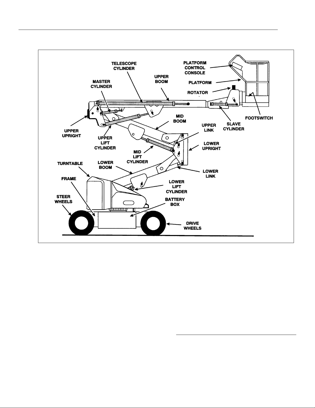
40/n40/45 electric - Boom. (See Figure 2-2)
1. Check Lower Boom and leveling link for damage,
missing part s and security.
2. Check all pin and shaft retaining hardware for secu-
rity and wear.
3. Check hydraulic lines and electrical cable for dam-
age, missing parts and security.
4. Check limit switch connections and plunger for cor-
rosion and security.
5. Check Lower Upright cross pins and hydraulic lines
for damage, wear, lubrication, leakage and security.
6. Check Lower Upright for damage, wear, lubrication
and security.
7. Check hydraulic lines mounted on upright for dam-
age, leakage and security.
8. Check Mid Boom pivot shaft and lift cylinder for
damage, missing parts and security.

SECTION 2 - PREPARATION AND INSPECTION
3120742 – JLG Lift – 2-3
Figure 2-1. Boom Nomenclature. (30/35/n35 electric)
SECTION 2 - PREPARATION AND INSPECTION
2-4 – JLG Lift – 3120742
9. Check al l pin and sh aft ret ainin g hardw are for secu-
rity and wear.
10. Check Upper Upright, cross pins and hydraulic lines
for damage, wear, lubrication, leakage and securi ty.
11. Check Upper Upright for damage , wear, lubrication
and security.
12. Check hydraulic lines mounted on upright for dam-
age, leakage and security.
13. Check Upper Boom Lift Cylinder and cross pins and
hydraulic lines for damage, wear, lubrication, leak-
age and security.
14. Check Upper Boom pivot pin for damage, wear,
lubrication and security.
15. Check Upper Boom for damage, missing parts and
security.
16. Check Upper Boom wear pads for damage, missing
parts and security.
17. Check Upper Boom telescope cylinder, cross pins
and hydraulic lines for damage, wear, lubrication,
leakage and security.
18. Check Platform Leveling Cylinder, cross pins and
hydraulic lines for damage, wear, lubrication, leak-
age and security.
Platform.
1. Check platform and control console for damage,
loose or missing part s , and security.
Figure 2-2. Boom No menclature. (40/n45/45electric)
SECTION 2 - PREPARATION AND INSPECTION
3120742 – JLG Lift – 2-5
2. Check control switches and levers for damage,
loose or missing parts, and security. Assure that
lever and lever lock functions properly.
3. Check control switches, levers and electrical con-
nections for tightness and evidence of corrosion,
and wiring for defects and chafing damage. Assure
that switches function properly.
4. Check footswitch for damage, loose or missing
parts, and security. Assure that footswitch functions
properly and that wiring has no defects or chafing.
5. Check (35/n35/40/n40/45 electric) platform rotator
mechanism for lubrication. Check hydraulic rotator
reservoir for leakage, damage, and security.
NOTE: Check all DANGER, WARNING, CAUTION, and
INSTRUCTION placards for legibility and security on
the entire machine
TO AVOID INJURY, DO NOT OPERATE M ACHINE IF ALL PL AC-
ARDS ARE NOT ON THE MACH INE OR ARE D EFACED AN D NOT
READABLE. USE OF MACHINE WITHO UT CORRECT PLAC-
ARDS.IS A SAFETY VIOLATION
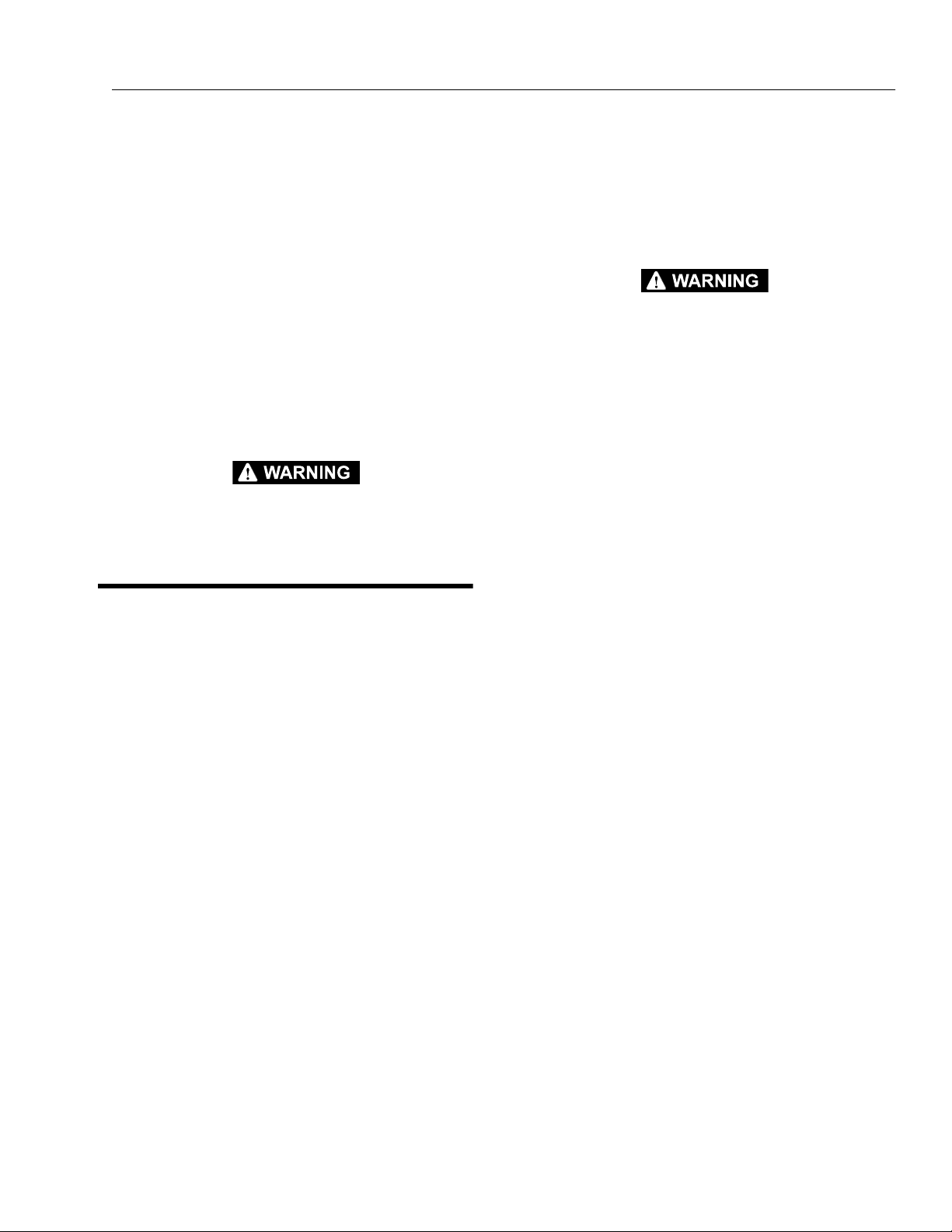
2.4 DAILY WALK-AROUND INSPECTION
It is the operators responsibilit y to inspect the machine
before the start of each workday. It is recommended that
each operator inspect the machine before operation, even
if the machine has already been put into service under
another operator. This Daily Walk-Around Inspection is the
preferred metho d of inspection.
These checks are also to be performed after maintenance
has been performed on the machine.
In addition to the Daily Walk-Around Inspection, be sure to
include the following as part of the daily inspection:
1. Overall cleanliness.
Check all standing surfaces for oil, fuel and hydrau-
lic oil spillage and foreign objects. Ensure overall
cleanliness.
2. Placards.
Keep all information and operating placards clean
and unobstructed. Cover when spray painting or
shot blasting to protect legibility.
3. Operator’s and Safety Manual.
Ensure a copy of this manual and the ANSI A92.5-
1992 Responsibilities, are enclosed in the manual
storage box.
4. Machine Log.
Ensure a machine operating record or log is kept,
check to see that it is current and that no entries
have been left uncleared, leaving machine in an
unsafe condition for opera tion.
5. Start each day with a full fuel tank.
TO AVOID INJURY, DO NOT OPERATE A MACHINE UNTIL ALL
MALFUNCTIONS HAVE BEEN CORRECTED. USE OF A MALFUNC-
TIONING MACHINE IS A SAFETY VIOLATION.
TO AVOID POSSIBLE INJURY, BE SURE MACHINE POWER IS
"OFF" DURING WALK-AROUND INSPECTION.
NOTE: Check boom limit switches on upright for proper
operation and security, both visually and manually.
The lower switch cuts out drive speed when the
lower boom is above horizontal. The upper switch
cuts out drive speed when the upper boom is above
horizontal. Only creep drive speed will continue to
function.
6. Check platform footswitch for proper operation.
Switch must be released to start engine and
depressed to operate machine.
7. Check that drive brakes hold when machine is
driven up a grade not greater than specified on the
serial number placard and stopped.
NOTE: On new machines, those recently overhauled, or
after changing hydraulic oil, operate all systems a
minimum of two complete cycles and recheck oil
level in reservoir.
8. Assure that all items requiring lubrication are ser-
viced. Refer to Lubrication Chart, Figure 2-3, for spe-
cific requirements.

SECTION 2 - PREPARATION AND INSPECTION
2-6 – JLG Lift – 3120742
1
2
3
4
5
6
7
8
9
10
11
12
13
14
17
15
16
17
18
20
21
22
22
23
24
25
26
27
28
29
30
Figure 2-3. Daily walk-around Inspection. (Sheet 1 of 3)
 Loading...