


Installation
Instructions
Durametallic® VRA & VRA-C Series
Outside balanced seals designed to operate under relatively high pressures and low speeds
Experience In Motion
1 Equipment Check
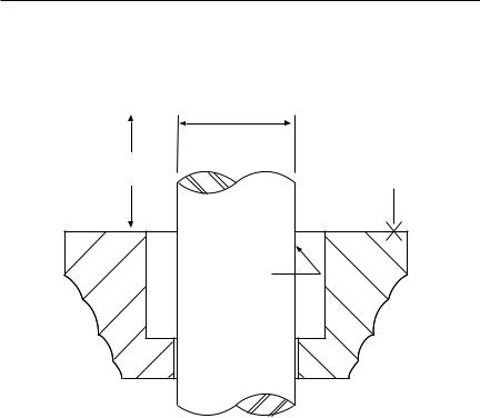
1.1Refer to Figure 1 for shaft, sleeve and seal housing requirements.
Seal Chamber Requirements |
Figure 1 |
Shaft or sleeve OD ±0.025 mm (±0.001 inch)
To first obstruction
Face of seal housing/vessel to be square to the axis of the shaft to within 0.5 mm (0.020 inch) FIM and have a 1.6 µm (√ 63 µinch) Ra finish or better
•Bearings, drive, and coupling must be in good condition
•Maximum axial movement of shaft (end play) = 0.25 mm (0.010 inch) FIM
•Maximum combined shaft concentricity and shaft deflection at face of housing total = 03.8 mm (0.150 inch) FIM
1.2Refer to assembly drawing included with seal package for specific seal design, materials of construction, dimensions, and piping connections.
1.3Check shaft or sleeve OD, box bore, and box depth to ensure that they are dimensionally the same as shown on the seal assembly drawing.
1.4Check gland pilot and bolt holes to ensure they are adaptable to the equipment and are the same as shown on the assembly drawing.
1.5Seal Faces: While all seal parts are manufactured to precise tolerances, the seal faces (stationary and rotating face) are of primary importance. These two sealing faces are lapped flat to three light bands or better (34.8 millionths of an inch) and polished. It is imperative that these two faces be handled with care and kept perfectly clean.
1.6Do not apply oil or other lubricants to the seal faces or to the secondary seals.
1.7Lightly lubricate the rotating face gasket and the O-ring on seal drive ID with a lubricant compatible with the application and elastomer materials.
2
 Loading...