


|
USER INSTRUCTIONS |
LimitorqueTM V Series |
Installation |
FCD LMENIM3601-01-AQ 02/15 |
Operation |
|
Maintenance |
|
|
Experience In Motion

LimitorqueTM V Series FCD LMENIM3601-01-AQ - 02/15
Contents
1 |
Introduction |
4 |
|||
|
|
|
1.1 |
Purpose |
4 |
|
|
|
1.2 |
User Safety |
4 |
|
|
2 |
Inspection, Installation and Mounting Procedures |
5 |
|
|
|
|
2.1 |
Initial Inspection and Storage Instructions |
6 |
|
|
|
2.2 |
Inspection and Recording |
6 |
|
|
|
2.3 |
Storage Procedure |
7 |
|
|
|
2.4 |
Safety Precautions |
7 |
|
|
|
2.5 |
Safety Practices |
7 |
|
|
|
2.6 |
General Mounting Instructions |
7 |
|
|
|
2.7 |
Stem Cover Mounting Instructions |
9 |
|
|
3 |
Lubrication |
10 |
|
|
4 |
Product Weights |
11 |
||
|
5 |
Disassembly and Reassembly Instructions |
12 |
||
|
|
|
5.1 |
Disassembly and Reassembly of V0 through V9 |
12 |
|
|
|
5.2 |
Disassembly and Reassembly of V35H through V9H |
15 |
|
|
|
5.3 |
Disassembly and Reassembly of Single Reduction Spur Gear Attachment (1S) |
18 |
|
|
|
5.4 |
Disassembly and Reassembly of Double Reduction Spur Gear Attachment (ISD) |
20 |
|
6 |
How to Order Parts |
22 |
||
2

LimitorqueTM V Series FCD LMENIM3601-01-AQ - 02/15
Figures
Figure 2.1 – V Exploded View |
5 |
||
Figure 2.2 – VH Exploded View |
6 |
||
Figure 5.1 |
– V0 |
– V9 Assembly View |
14 |
Figure 5.2 |
– V35H – V9H Assembly View |
17 |
|
Figure 5.3 |
– V0 |
– V9, and V35H – V9H Spur Gear Attachment (1S) Exploded View |
19 |
Figure 5.4 |
– V0 |
– V9, and V35H – V9H Spur Gear Attachment (1SD) Exploded View |
21 |
Tables
Table 3.1 – Lubricants |
10 |
|
Table 4.1 – V Gearbox Weights |
11 |
|
Table 4.2 – VH Gearbox Weights |
11 |
|
Table 5.1 |
– V0 Through V9 Parts List |
14 |
Table 5.2 |
– V35H Through V9H Parts List |
17 |
Table 5.3 |
– V and VH Spur Gear Attachment (1S) Parts List |
19 |
Table 5.4 |
– V and VH Spur Gear Attachment (1SD) Parts List |
21 |
3
flowserve.com

LimitorqueTM V Series FCD LMENIM3601-01-AQ - 02/15
1 Introduction
1.1 Purpose
The installation, operation, and maintenance manual (IOM) explains how to install, operate, and maintain the Flowserve Limitorque V gearbox. Information on installation, disassembly, reassembly, lubrication and product weights is provided.
1.2 User Safety
Safety notices in this manual detail precautions the user must take to reduce the risk of personal injury and damage to the equipment. The user must read and be familiar with these instructions before attempting installation, operation or maintenance. Failure to observe these precautions could result in serious bodily injury, damage to the equipment, voiding of the warranty, or operational difficulty.
Safety notices are presented in this manual in three forms:
c |
WARNING: Refers to personal safety. Alerts the user to potential danger. Failure to follow warning notices could |
|
result in personal injury or death. |
aCAUTION: Directs the user’s attention to general precautions that, if not followed, could result in personal injury and/or equipment damage.
NOTE: Highlights information critical to the user’s understanding of the V gearbox’s installation and operation.
4
LimitorqueTM V Series FCD LMENIM3601-01-AQ - 02/15
2 Inspection, Installation and
Mounting Procedures
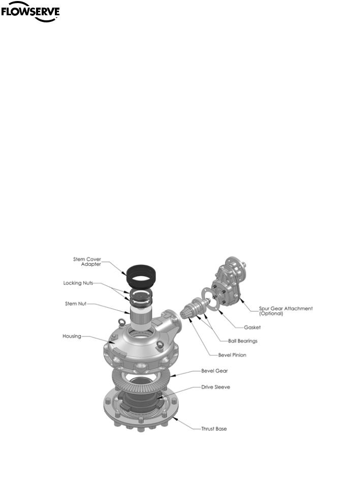
Figure 2.1 - V Exploded View
5
c WARNING: Do not manually operate the V gearbox with devices other than the installed handwheel or wrench nut. Using additive force devices (cheater bars, wheel wrenches, pipe wrenches, or other devices of this nature) on the gearbox handwheel, wrench or wrench nut may cause serious personal injury and/or damage to the gearbox or valve.
flowserve.com
LimitorqueTM V Series FCD LMENIM3601-01-AQ - 02/15
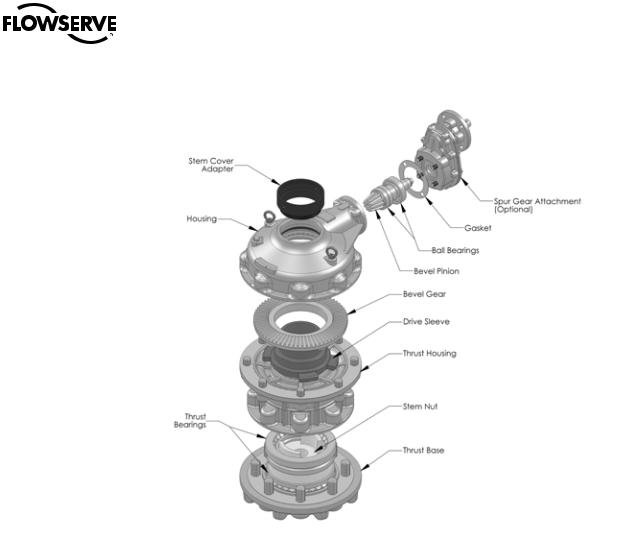
Figure 2.2 - VH Exploded View
2.1 Initial Inspection and Storage Instructions
c WARNING: Read this installation and maintenance manual carefully and completely before attempting to store the gearbox. If an electric actuator is attached to the V gearbox, be aware of the electrical hazards. Consult the electric actuator installation and maintenance manual for guidance.
2.2 Inspection and Recording
Upon receipt of the gearbox, inspect the condition of the equipment, and record nameplate information.
1. Carefully remove the gearbox from the shipping carton or skid. Thoroughly examine the equipment for any physical damage that may have occurred during shipment. If damaged, immediately report the damage to the transport company.
2. A nameplate is attached to each gearbox with the following information:
• Gearbox size
• Order number
• Serial number
• Customer tagging
6 |
Record this information for future reference, e.g., ordering parts, or obtaining further information. |
|

LimitorqueTM V Series FCD LMENIM3601-01-AQ - 02/15
2.3 Storage Procedure
NOTE: The following is the recommended storage procedure to retain maximum product integrity during storage. Failure to comply with recommended procedure will void the warranty.
Storage (less than one year)
Store the gearboxes on wooden skids to protect the machined mounting flange. Place the wooden skids containing the gearboxes in a clean, dry, protected warehouse. If the gearboxes must be stored outside, they must be covered in polyethylene protection with silica gel crystals to absorb moisture. If an electric actuator is attached to the V gearbox, refer to the storage procedures in its respective manual for appropriate storage procedures. Rotate input shafts every three months to mix the lubricant.
2.4 Safety Precautions
c WARNING: Read this Installation, Operation and Maintenance manual carefully and completely before attempting to install, operate or troubleshoot the Limitorque gearbox.
c WARNING: Potential HIGH-PRESSURE vessel — be aware of high-pressure hazards associated with the attached valve or other actuated device when installing or performing maintenance on the gearbox. Do not remove the gearbox mounting bolts from the valve or actuated device unless the valve or device stem is secured or there is no pressure in the line.
c WARNING: For maintenance and/or disassembly of the gearbox while installed on the valve, ensure that the gearbox is not under thrust or torque load. If the valve must be left in service, the valve stem must be locked in such a way as to prevent any movement of the valve stem.
c WARNING: Do not manually operate the gearbox with devices other than the installed handwheel. Using force beyond the ratings of the gearbox and/or using additive force devices such as cheater bars, wheel wrenches, pipe wrenches, or other devices on the gearbox handwheel may cause serious personal injury and/or damage to the gearbox and valve.
c c
WARNING: Do not exceed any design limitations or make modifications to this equipment without first consulting Flowserve Limitorque.
WARNING: Use of this product must be suspended any time it fails to operate properly.
aCAUTION: If a motor actuator is driving the gearbox, do not operate the valve under motor operation without first checking and setting the limit switch and checking for correct motor rotation.
aCAUTION: Do not use replacement parts that are not genuine Flowserve Limitorque parts, as serious personal injury and/or damage to the gearbox and valve may result.
2.5 Safety Practices
The following checkpoints should be performed to maintain safe operation of the V gearbox:
•Set up a periodic operating schedule on infrequently used valves.
•Ensure that the limit and/or torque switches on any electric actuator fitted to the V gearbox are correctly and appropriately adjusted.
2.6 General Mounting Instructions
The mounting instructions for the V bevel gearboxes are outlined below. The V0 through V9 gearboxes are designed with a splined top-entry Stem Nut which is retained in the Drive Sleeve by two Lock Nuts.
The V35H through V9H gearboxes are designed with a Stem Nut which is retained by two Thrust Roller Bearings within the Thrust Housing and |
7 |
Thrust Base. Partial disassembly of the Thrust Base is required for Stem Nut removal and/or installation. |
|
flowserve.com

LimitorqueTM V Series FCD LMENIM3601-01-AQ - 02/15
2.6.1Installing a Gearbox with a Threaded Stem Nut – V0 through V9 and V35H through V9H
1.Position the gearbox above the valve stem.
2.Rotate the gearbox handwheel or wrench nut several turns until there is positive engagement between the valve stem and the gearbox Stem Nut.
3.Rotate the handwheel to lower the gearbox onto the valve until contact has been made with the valve fllange.
4.Bolt the gearbox securely to the valve mounting fllange.
2.6.2 Installing a Gearbox with a Blank Stem Nut – V0 through V9
1. Remove the two threaded Lock Nuts (pc# 7) from the Drive Sleeve (pc# 6), accessed through the top of the Housing (pc# 1). 2. Remove the Stem Nut (pc# 5) from the Drive Sleeve (pc# 6) through the top of the Housing (pc# 1).
3. Machine the Stem Nut (pc# 5) to suit the valve stem.
a CAUTION: Care must be taken to ensure that the clamping devices used during machining do not damage splined surfaces of the Stem Nut. 4. Reinstall the Stem Nut (pc# 5) into the Drive Sleeve (pc# 6), ensuring the splines are properly engaged.
5. Reinstall the two threaded Lock Nuts (pc# 7) into the Drive Sleeve (pc# 6).
6. Mount the gearbox on the valve as detailed in Section 2.6.1 Installing a Gearbox with a Threaded Stem Nut.
2.6.3 Installing a Gearbox with a Blank Stem Nut – V35H through V9H
|
1. |
Place the gearbox upside down to access the mounting base. |
|
2. |
Remove the Socket Head Cap Screws (pc# 34) which mount the Thrust Base (pc# 31) to the Thrust Housing (pc# 2). |
|
3. |
Remove the Thrust Base (pc# 31) and Gasket (pc# 32) from the Thrust Housing (pc# 2). |
|
a |
CAUTION: Care must be taken to ensure that the O-ring (pc# 15) located in the Thrust Base (pc# 31) is not damaged during disassembly. |
|
4. |
Remove the Stem Nut (pc# 5) and lower Thrust Roller Bearing (pc# 33). |
|
5. |
Remove the upper Thrust Roller Bearing (pc# 33). Place all bearings in a clean, dry area until reassembly. |
|
6. |
Machine the Stem Nut (pc# 5) to suit the valve stem. |
|
a CAUTION: Care must be taken to ensure that the clamping devices used during machining do not damage splined surfaces of the |
|
|
|
Stem Nut (pc# 5). |
|
7. |
Reinstall the upper Thrust Roller Bearing (pc# 33) into the Thrust Housing (pc# 2). |
|
8. |
Install the Stem Nut (pc# 5) into the Thrust Housing (pc# 2) and upper Thrust Roller Bearing (pc# 33). |
|
9. |
Install the lower Thrust Roller Bearing (pc# 33) onto the Stem Nut (pc# 5). |
|
10. |
Place the Gasket (pc# 32) onto the Thrust Housing (pc# 2). |
8 |
11. |
Separately, install the O-Ring (pc# 15) in the Thrust Base (pc# 31). |
 Loading...