


®
Pump Division
Model: VCT
VERTICAL CENTRIFUGAL PUMPS
USER INSTRUCTIONS: INSTALLATION, OPERATION AND
MAINTENANCE for self lubricated pump
User Instructions No. MX0301 - 07/03 (E)

USER INSTRUCTIONS APM, APMA and APH MX0301 - 07/03
®
CONTENTS
PAGE
1 |
INTRODUCTION AND |
|
3 |
6 |
MAINTENANCE |
|
11 |
|
SAFETY |
|
|
6.1 |
General……… ………………….. |
11 |
|
1.1 |
General……………………… |
….. |
3 |
6.2 |
Maintenance schedule………… |
|
12 |
1.2 |
CE marking and approvals……. |
3 |
6.3 |
Spare parts…………………….. |
13 |
|
|
1.3 |
Disclaimer………………………. |
3 |
|
6.4 |
Recommended spares and |
|
13 |
1.4 |
Copyright………………………... |
3 |
|
|
consumable items……………… |
|
|
1.5 |
Duty conditions…………………. |
3 |
|
6.5 |
Tools required………………….. |
13 |
|
1.6 |
Safety…………………………… |
. |
3 |
6.6 |
Fastener torques………………. |
13 |
|
1.7 |
Nameplate and warning labels.. |
5 |
6.7 |
Renewal clearances…………… |
|
14 |
|
1.8 |
Specific machine performance.. |
5 |
6.8 |
Disassembly……………………. |
14 |
|
|
1.9 |
Noise level……………………… |
|
5 |
6.9 |
Examination of parts…………... |
15 |
|
2 |
TRANSPORT AND STORAGE |
5 |
6.10 |
Assembly……… ……………….. |
16 |
||
|
|
|
|
||||
2.1 |
Consignment and unpacking…. |
6 |
7 |
FAULTS;CAUSESANDREMEDIES |
18 |
||
2.2 |
Handling………………………… |
|
6 |
|
|
|
|
2.3 |
Lifting……………………………. |
6 |
|
8 |
PARTS LIST AND DRAWINGS |
19 |
|
2.4 |
Storage………………………….. |
7 |
|
8.1 |
Typical sectional drawings……. |
19 |
|
2.5 |
Recycling and end of product |
7 |
8.2 |
Parts list………………………… |
|
26 |
|
|
life |
|
|
8.3 |
General arrangement drawing.. |
26 |
|
3 |
PUMP DESCRIPTION |
|
7 |
9 |
CERTIFICATION |
|
26 |
3.1Configurations………………….. 7
3.2 |
Design of mayor parts…………. |
7 |
10 |
SUPPLEMENTARY INFORMATION |
27 |
3.3 |
Performance and operating |
|
10.1 |
Long term storage……… ………….. |
27 |
|
limits……………………………... |
7 |
10.2 |
Coupling alignment……………. |
30 |
|
|
|
|
Procedure |
|
4 |
INSTALLATION |
7 |
10.3 |
Gasket eliminator application… |
31 |
4.1Location…………………………. 7
4.2 |
Part assemblies………………… |
|
8 |
|
OTHERRELEVANTDOCUMENTATION |
1 |
4.3 |
Foundation……………………… |
|
8 |
11 |
31 |
|
4.4 |
Grouting………………………… |
|
8 |
|
ANDMANUALS |
|
4.5 |
Alignment………………………. |
8 |
|
11.1 |
Supplementaryuserinstructions………. |
31 |
4.6 |
Piping………………………… |
.… |
9 |
11.2 |
Change notes………………… ... |
31 |
4.7 |
Final alignment check…………. |
9 |
11.3 |
Additional sources of …………. |
31 |
|
4.8 |
Electrical connections…………. |
9 |
|
Information |
|
|
|
|
|
|
11.4 |
Customer service information… |
32 |
5 |
COMMISSIONING,START-UP, |
|
9 |
|
|
|
|
OPERATIONANDSHUTDOWN |
|
|
|
|
|
5.1Pre-commissioning procedure.. 9
5.2 Motor lubricants………………… |
9 |
5.3Direction of rotation……………. 9
5.4 Guarding………………………… |
10 |
5.5Rotor setting……………………. 10
5.6 Starting the pump……………… |
10 |
5.7Running the pump……………... 11
5.8Stopping and shutdown……….. 11
5.9Emergency shutdown…………. 11
Page 2 of 32

USER INSTRUCTIONS APM, APMA and APH MX0301 - 07/03
®
1 INTRODUCTION AND SAFETY
1.1 General
 These instructions must always be kept close to the product's operating location or directly with the product.
Flowserve's products are designed, developed and manufactured with state-of-the-art technologies in modern facilities. The unit is produced with great care and commitment to continuous quality control, utilising sophisticated quality techniques, and safety requirements.
We are committed to continuous quality improvement and being at your service for any further information about the product in its installation and operation or about its support products, repair and diagnostic services.
These instructions are intended to facilitate familiarization with the product and its permitted use. Operating the product in compliance with these instructions is important to help ensure reliability in service and avoid risks. The instructions may not take into account local regulations; ensure such regulations are observed by all, including those installing the product. Always coordinate repair activity with operations personnel, and follow all plant safety requirements and applicable safety and health laws and regulations.
of Flowserve Corporation to provide sound and all necessary information the content of this manual may appear insufficient and is not guaranteed by Flowserve as to its completeness or accuracy.
Flowserve manufactures products to exacting International Quality Management System Standards as certified and audited by external Quality Assurance organisations. Genuine parts and accessories have been designed, tested and incorporated into the products to help ensure their continued product quality and performance in use. As Flowserve cannot test parts and accessories sourced from other vendors the incorrect incorporation of such parts and accessories may adversely affect the performance and safety features of the products. The failure to properly select, install or use authorised Flowserve parts and accessories is considered to be misuse. Damage or failure caused by misuse is not covered by Flowserve's warranty. In addition, any modification of Flowserve products or removal of original components may impair the safety of these products in their use.
1.4 Copyright
All rights reserved. No part of these instructions may be reproduced, stored in a retrieval system or transmitted in any form or by any means without prior permission of Flowserve Pump Division.
 These instructions should be read entirely prior to installing, operating, using and maintaining the equipment in any region worldwide. The equipment must not be put into service until all the conditions relating to safety noted in the instructions, have been met.
1.2 CE marking and approvals
It is a legal requirement that machinery and equipment put into service within certain regions of the world shall conform with the applicable CE Marking Directives covering Machinery and, where applicable, Low Voltage Equipment, Electromagnetic Compatibility (EMC), Pressure Equipment Directive (PED) and Equipment for Potentially Explosive Atmospheres (ATEX), American National Standards Institute (ANSI), Institute of Electrical and Electronics Engineers (IEEE), International Electrotechnical Commission (IEC), National Electrical Manufacturers Association (NEMA), National Fire Protection Association (NFPA).
1.3 Disclaimer
Information in these User Instructions is believed to be reliable. In spite of all the efforts
1.5 Duty conditions
This product has been selected to meet the specifications of your purchaser order. The acknowledgement of these conditions has been sent separately to the Purchaser.
 The product must not be operated beyond the parameters specified for the application. If there is any doubt as to the suitability of the product for the application intended, contact Flowserve for advice, quoting the serial number.
If the conditions of service on your purchase order are going to be changed (for example liquid pumped, temperature or capacity) it is requested that you/the user seek our written agreement before start up.
1.6 Safety
1.6.1 Summary of safety markings
These user instructions contain specific safety markings where non-observance of an instruction would cause hazards. The specific safety markings are:
Page 3 of 32

USER INSTRUCTIONS APM, APMA and APH MX0301 - 07/03
®
 This symbol indicates electrical safety instructions where non-compliance would affect personal safety.
 This symbol indicates safety instructions where non-compliance would affect personal safety.


 This symbol indicates safety instructions where non-compliance would affect protection of a safe life environment.
 This symbol indicates safety instructions where non-compliance would affect the safe operation or protection of the pump unit.
 This symbol indicates explosive atmosphere zone marking according to ATEX. It is used in safety instructions where non-compliance in the hazardous area would cause the risk of an explosion.
 This sign is not a safety symbol but indicates an important instruction in the assembly process.
1.6.2 Personnel qualification and training
All personnel involved in the operation, installation, inspection and maintenance of the unit must be qualified to carry out the work involved. If the personnel in question do not already possess the necessary knowledge and skill, appropriate training and instruction must be provided. If required the operator may commission the manufacturer/supplier to provide applicable training.
Always coordinate repair activity with operations and health and safety personnel, and follow all plant safety requirements and applicable safety and health laws and regulations.
1.6.3 Safety action
This is a summary of conditions and actions to prevent injury to personnel and damage to equipment.
 LEVELED FUNDATION PLATE Fundation plate or suction barrel flange must be leveled within 0.050mm ( 0.002 in.) as maximum variation which is indispensable for operation free of trouble.
Use a rectified long bar in order to support precision level across the foundation plate (side-to- side) and levelling all directions every 45 degrees.
Foundation plate must be verified before and after pour the grouting.
 PREVENT EXCESSIVE EXTERNAL PIPE LOAD
a)Do not use pump as a support for piping. Piping must be independently supported and must not be drawn into position with flange bolting. Pipe strains on the pump can be a definite source of trouble, resulting in possible misalignment, excessive wear, vibration and even broken shafts.
b)If expansion joint is used, employ tie rods of adequate strength (i.e. size for 1-1/2 times shut off pressure).
c)Ensure pump and piping is flushed before use .
 ENSURE CORRECT LUBRICATION
When external water source or oil is needed for lubrication-see General Arrangement Drawing. (See drawings attached)
 See section 5.3, Direction of rotation before connecting the motor to the electrical supply.
 START THE PUMP WITH OUTLET VALVE PART OPENED 30%.
(Unless otherwise instructed at a specific point in the user instructions, see section 5,
Commissioning, start up, operation and shutdown.) This is recommended to minimize the risk of overloading and damaging pump motor at full or zero flow. The pump outlet control valve may need to be adjusted to comply with the duty following the run-up process.
 DO NOT RUN THE PUMP AT ABNORMALLY HIGH OR LOW FLOW RATES Operating at a flow rate higher or lower than normal may overload the motor and cause cavitation, instability and vibration.
 NEVER DO MAINTENANCE WORK WHEN THE UNIT IS CONNECTED TO POWER


 HAZARDOUS LIQUIDS
When the pump is handling hazardous liquids care must be taken to avoid exposure to the liquid by appropriate sitting of the pump, limiting personnel access and by operator training. If the liquid is flammable and/or explosive, strict safety procedures must be applied.
 HANDLING COMPONENTS
Many precision parts have sharp corners and the wearing of appropriate safety gloves and equipment is required when handling these components. To lift heavy pieces above 25 kg (55 lb) use a crane appropriate for the mass and in accordance with current local regulations.
Page 4 of 32
USER INSTRUCTIONS APM, APMA and APH MX0301 - 07/03
®
 LIFTING DEVICES
Mounted on individual parts are intended for lifting the individual part only. Lifting slings must not put excessive side thrust on the lifting device.
 GUARDS MUST NOT BE REMOVED WHILE THE PUMP IS OPERATIONAL
 LIFTING ROTOR
Lifting rotor must be setting before start up the pump, according nameplate. See point 5.5
 FLUORO-ELASTOMERS (When fitted.) When a pump has experienced temperatures over 250 ºC (482 ºF), partial decomposition of fluoroelastomers (eg Viton) will occur. In this condition these are extremely dangerous and skin contact must be avoided.
 HANDLING COMPONENTS
Many precision parts have sharp corners and the wearing of appropriate safety gloves and equipment is required when handling these components. To lift heavy pieces above 25 kg (55 lb) use a crane appropriate for the mass and in accordance with current local regulations.
1.6.4 Products used in potentially explosive atmospheres
 Measures are required to:
∙Avoid excess temperature
∙Prevent build up of explosive mixtures
∙Prevent the generation of sparks
∙Prevent leakages
∙Maintain the pump to avoid hazard
The following instructions for pumps and pump units when installed in potentially explosive atmospheres must be followed to help ensure explosion protection. Both electrical and nonelectrical equipment must meet the requirements of European Directive 94/9/EC.
1.6.4.1 Scope of compliance
 Use equipment only in the zone for which it is appropriate. Always check that the driver, drive coupling assembly, seal and pump equipment are suitably rated and/or certified for the classification of the specific atmosphere in which they are to be installed.
Where Flowserve has supplied only the bare shaft pump, the Ex rating applies only to the pump. The
party responsible for assembling the pump set shall select the coupling, driver and any additional equipment, with the necessary CE Certificate/ Declaration of Conformity establishing it is suitable for the area in which it is to be installed.
1.6.4.6 Preventing leakage
 The pump must only be used to handle liquids for which it has been approved to have the correct corrosion resistance.
1.7 Nameplate and warning labels
1.7.1 Nameplate
Every pump has a name plate made in stainless steel with information regarding operating condition as capacity, total dynamic head, rotational speed, specific gravity, rotor setting, power consumption and serial number.
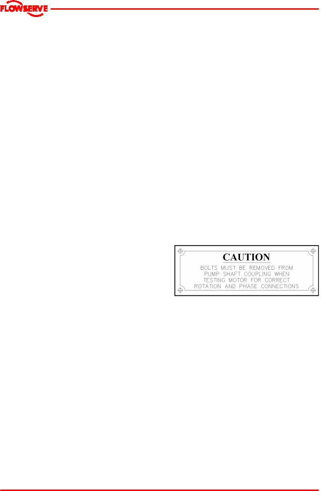
1.7.2 Warning labels
A stainless steel plate is attached to discharge head requesting removing coupling bolts before checking motor rotation and avoid damage to the equipment.
1.8 Specific machine performance
For performance parameters see data sheet and performance curve in this User Instructions.
1.9 Noise level
When pump noise level exceeds 85 dBA attention must be given to prevailing Health and Safety Legislation, to limit the exposure of plant operating personnel to the noise. The usual approach is to control exposure time to the noise.
Pump noise level is dependent on a number of factors - the type of motor fitted, the operating capacity, pipework design and acoustic characteristics of the building.
2 TRANSPORT AND STORAGE
Page 5 of 32

USER INSTRUCTIONS APM, APMA and APH MX0301 - 07/03
®
2.1 Consignment receipt and unpacking
Immediately after receipt of the equipment it must be checked against the delivery/shipping documents for its completeness and that there has been no damage in transportation. Any shortage and/or damage must be reported immediately to Flowserve Pump Division and must be received in writing within one month of receipt of the equipment. Later claims cannot be accepted.
Check any crate, boxes or wrappings for any accessories or spare parts that may be packed separately with the equipment or attached to side walls of the box or equipment.
Each product has a unique serial number. Check that this number corresponds with that advised and always quote this number in correspondence as well as when ordering spare parts or further accessories. For Flowserve contact see point 11.4
For installing pump handle the pump as follow:
2.2 Handling
Boxes, crates, pallets or cartons may be unloaded using fork-lift vehicles or slings dependent on their size and construction.
2.3 Lifting
 To avoid distortion, the pump unit should be lifted as shown. All lifting should be done using the lifting points that have been provided.
(See the outline drawing for location, size configuration and for total equipment weight.) Arrange any slings, chains or cables so that the weight is distributed uniformly. Use spread bars when necessary to avoid undue pressure on light sheet metal parts.
If lifting lugs are provided on discharge head baseplate lift it as shown.
If lifting lugs are provided in the top of discharge head , lift it as follow.
Page 6 of 32

USER INSTRUCTIONS APM, APMA and APH MX0301 - 07/03
®
 Fully trained personnel must carry out lifting, in accordance with local regulations. The driver and pump weights are recorded on their respective General Arrangement Drawing.
2.4 Storage
 Store the pump in a clean, dry location away from vibration. Equipment stored in horizontal position must be placed upon enough skids or wood blocks to prevent contact with ground and surface contaminants. Leave piping connection covers in place to keep dirt and other foreign material out of pump casing.
Renew the preservative coating in areas where it has been rubbed off or scraped including internal areas and replace covers on openings.
Touch up the areas has been chipped or scraped. Twice a month 180° rotation of pump is needed in order to decrease shaft distortion due to horizontal storage.
Longer storage periods (more than 5 months), it is required to create and store the pump fully disassembled when it has rubber bearings in order to prevent rubber bearings deformation. Contact Flowserve´s representative when longer than 5 months storage will be done ( See section 10 )
2.5 Recycling and end of product life
At the end of the service life of the product or its parts, the relevant materials and parts should be recycled or disposed of using an environmentally acceptable method and in accordance with local regulations. If the product contains substances that are harmful to the environment, these should be removed and disposed of in accordance with current local regulations.


 Make sure that hazardous substances are disposed of safely and that the correct personal protective equipment is used. The safety specifications must be in accordance with the current local regulations at all times.
3 PUMP DESCRIPTION
3.1 Name nomenclature
The pump size will be engraved on the nameplate as exemplar below:
65 APM
Where:
Nominal size: 65 Pump type: APM
The typical nomenclature above is the general guide. Identify the actual pump size and serial number from the pump nameplate. Check that this agrees with the applicable certification provided.
3.2 Design of major parts
3.2.1 Bowl.
The pump has its main part in the bowl which conducts liquid from impeller to column pipe and converts to pressure the velocity added by the impeller.
3.2.2 Impeller
The impeller is semi-open type and it is dynamically balanced
3.2.3 Shaft
The large diameter stiff shaft, supported by bearings is accurately machined.
3.2.4 Bearings and lubrication
Bearings are fitted as standard and are lubricated by pumped liquid.
3.2.5 Suction bell
This piece approaches liquid to impeller eye in optimum way.
3.2.6 Stuffing box housing
The stuffing box contains packing which controls leakage thru pump shaft passage.
3.2.7 Driver
The driver is normally an electric motor. Different drive configurations may be fitted such as internal combustion engines, turbines, hydraulic motors etc. driving via couplings, belts, gearboxes, drive shafts etc.
3.2.8 Accessories
Accessories may be fitted when specified by the customer on data sheet or purchase order.
3.3 Performance and operating limits
This pump has been selected to meet the specifications of your purchase order for more details see attachment in this User Instructions.
4 INSTALLATION
 Equipment operated in hazardous locations must comply with the relevant explosion protection regulations.
4.1 Location
The pump should be located to allow room for access, ventilation, maintenance and inspection
Page 7 of 32
USER INSTRUCTIONS APM, APMA and APH MX0301 - 07/03
®
with ample headroom for lifting it. Refer to the general arrangement drawing for the pump set.
4.2 Part assemblies
Motor is typically supplied loose. It is the responsibility of the installer to ensure that the motor is assembled to the pump and lined up as detailed in section 4.5.2 and 5.5
4.3 Foundation
 The foundation should be sufficiently substantial to absorb vibration and to form a permanent, rigid support for the pump. The mass of the foundation it is considered that foundation has an infinite mass since there will not be resonance between pump mass and foundation mass.
The combined resonant frequency of the pump, motor, foundation and discharge piping has been calculated to be sufficiently removed from the rotational speed so that no vibration amplification will occur. This analytical model has been based upon the following:
A). A rigid foundation support system that has a stiffness of at least 2.5 x 10⁵ lb/ft. It has been assumed that the pump foundation provides no lateral deflection to the combined assembly.
B). An assumed discharge piping stiffness has been used to simulate the effect of the discharge piping.
Non-compliance with the provision of correct foundation and installation may lead to failure of the pump and, as such, would be outside the terms of the warranty.
4.4 Grouting
After levelling foundation plate, soleplate or suction barrel flange at 0.050mm (0.002 in.) maximum, using a straight bar which cross the sole plate side- to-side and a precision level device. Pour the grouting in order to fill the cavity below the foundation plate. It is important that a non-shrink type of grout be used. Ordinary cement, sand and water mixtures tend to shrink as the water evaporates, often leaving the underside of the foundation plate insufficiently supported. It is recommended that grouting be performed by a qualified grouting contractor. If in any doubt, see attachment in this user instructions or please contact your nearest service centre.
Grouting provides solid contact between the pump unit and foundation, prevents lateral movement of running equipment and dampens resonant vibrations.
Foundation bolts should only be fully tightened when the grout has cured.
4.5 Alignment
4.5.1 Thermal expansion
 The pump and motor will normally have to be aligned at ambient temperature and thermal expansion occurs after running at operating temperature. After eight hours of operation shut down and check the alignment immediately.
4.5.2 Alignment method
 Ensure pump and driver are isolated electrically and the half couplings are disconnected.
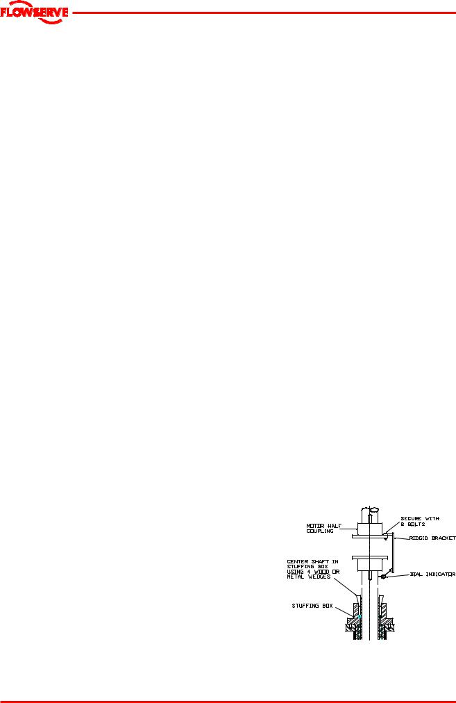
 The alignment MUST be checked to ensure successful operation using dial indicators as follow:
a)Before mounting the motor check rotation (see point 5.3 ).
b)Support driver vertically, shaft facing down and thoroughly clean the shaft and mounting faces.
c)Install motor half coupling with its key and split ring on motor shaft, pull it down to seat firmly against the split ring.
d)Install pump half coupling and adjusting nut.
e)Using a dial indicator mounted to the driver half coupling, rotate driver shaft to take readings from the pump shaft, and move the driver as necessary to align driver and pump shaft within 0.002” ( 0.03 mm) total indicator run out and tighten driver mounting fasteners.(see Rotor setting point 5.3)
f)Refer to driver manufacturer’s manual for driver operating instructions and lubrication. ( See point 10.2 )
Page 8 of 32

USER INSTRUCTIONS APM, APMA and APH MX0301 - 07/03
®
4.6 Piping
 Protective covers are fitted to the discharge flange, pipe connections and suction head, to prevent foreign bodies entering during transportation and installation. Ensure that these covers and shipping brace are removed from the pump before connecting any pipes.
 Never use the pump as a support for piping.
Maximum forces and moments allowed on the pump flanges vary with the pump size and type (see general arrangement drawing for specific values). To minimize these forces and moments that may, if excessive, cause misalignment, vibration and the possible failure of the pump , the following points should be strictly followed:
∙Prevent excessive external pipe load, design piping system to minimize pump nozzle loads.
∙Permit no excessive strain on the pump discharge flange
∙Never draw piping into place by applying force to pump flange connections
∙Provide expansion joints with tie rods of suitable strength ( sized for 1 ½ times shut off pressure).
∙Discharge valve should be located at least one pipe diameter from face of pump discharge flange.
∙Special considerations and provisions must be made to avoid the chance of water-hammer during pump operation and start up pump.
 Ensure piping is flushed before use.
4.8.3 The motor must be wired up in accordance with the motor manufacturer's instructions in this user instructions including any temperature, earth leakage, current and other protective devices as appropriate. The identification nameplate should be checked to ensure the power supply is appropriate.
4.8.4 A device to provide emergency stopping must be fitted.
4.8.5The controller/starter electrical details will also be supplied within the controller/starter when applied.
4.8.6  See section 5.3, Direction of rotation before connecting the motor to the electrical supply.
5 COMMISSIONING, START-UP, OPERATION AND SHUTDOWN
 These operations must be carried out by fully qualified personnel.
5.1 Pre-commissioning procedure
5.1.1 Lubrication
Determine the mode of lubrication of the pumpmotor set and supply it.
5.2 Motor lubricants
See Motor’s manual and motor outline in attachment in these User Instructions for motor lubrication details before any start up or test.
4.7 Final shaft alignment check
After connecting piping to the pump, rotate the shaft several times by hand to ensure there is no binding and all parts are free.
Recheck the coupling alignment, as previously described, to ensure no pipe strain. If pipe strain exists, correct piping, see point 4.5.2
4.8 Electrical connections
4.8.1 Electrical connections must be made by a qualified Electrician in accordance with relevant local national and international regulations.
4.8.2 It is important to be aware of the potentially explosive areas where compliance is an additional requirement for making electrical connections.
5.3 Direction of rotation
 Ensure the pump motor is given the same rotation as the pump direction arrow marked on the pump nameplate and Outline Drawing.
Some vertical motors are required to have non reverse couplings (non reverse device), to avoid pump-motor back spinning do to water column flow back during shutdown.
However the device is designed to support the forces developed by the pump, when the water is flowing back, which is increase gradually, the device is not expected to support the motor torque, which is suddenly applied as a shock a would damage the pins or ratchet plate teeth; Base on this, the motor must never be started against the ratchet pins, to avoid pins or ratchet plate damage
Page 9 of 32
USER INSTRUCTIONS APM, APMA and APH MX0301 - 07/03
®
and as in consequence, catastrophic failure to the top parts of the motor.
If the phase sequence of the incoming motor power cables is not positively known and the motor is to be “bumped” for rotation check, the ratchet pins must be removed from the pin carrier, to avoid the expected damage to the non reverse device.
The pins removal is under customer or motor installer responsibility.
Whenever the dismantling of couplings is necessary, the use of witness marks will assure a balanced condition when assembly is complete.
 If maintenance work has been carried out to the site's electricity supply, the direction of rotation should be re-checked as above in case the supply phasing has been altered.
It is recommended that records be kept pf the steady state uncoupled vibration and bearing temperatures to use for comparison with coupled and loaded conditions, and to provide a data base for judging the motor’s performance in the future. These records should be permanently retained for reference.
5.4 Guarding
 Guarding is supplied fitted to the pump set. If this has been removed or disturbed ensure that all the protective guards around the pump coupling and exposed parts of the shaft are securely fixed.
5.5 Rotor Setting
 Before pump start up, it is required adjust the impeller setting and avoid rubbing between impeller and impeller liner which can damage severely the pump, Rotor setting is specified on pump nameplate and pump outline drawing.
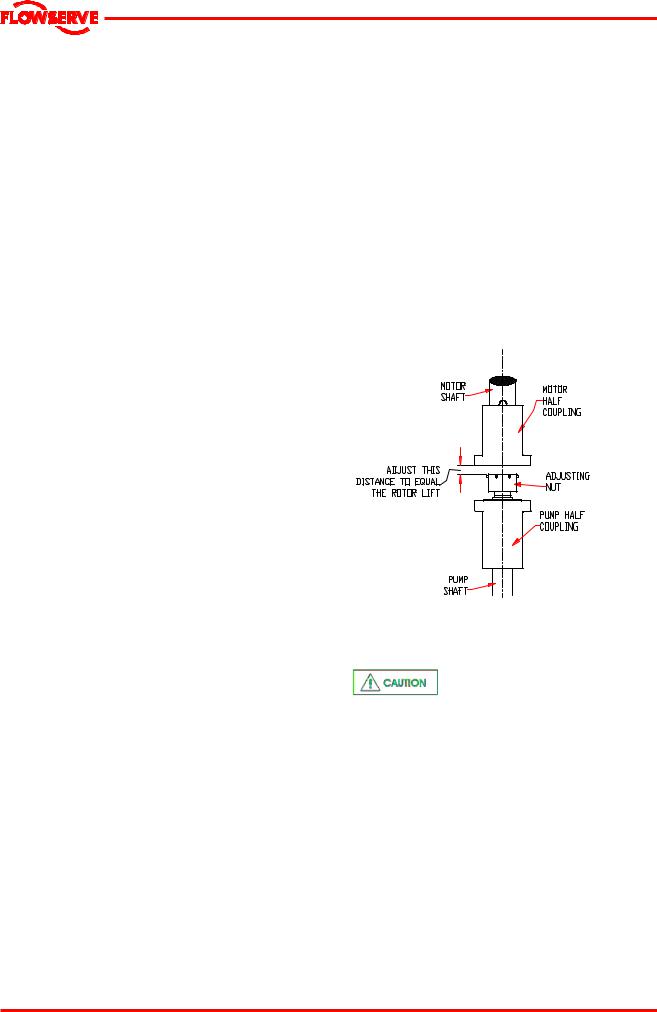
Follow next procedure in order to adjust the rotor setting:
a)Fit motor half coupling on motor shaft.
b)Fit split ring on motor shaft and move motor half coupling until it covers the split ring.
c)Fit pump half coupling on the pump top shaft.
d)Fit adjusting nut on the pump top shaft.
e)Adjust separation between adjusting nut and motor half coupling at rotor setting specified on nameplate; Use feeler gages.
f)Turn motor half coupling so bolt holes will line up with the bolt holes in the pump half coupling
g)Insert two of the coupling bolts and tighten progressively until secure, thereby closing the gap above the adjusting nut and raising rotor to running position.
h)Insert the remaining bolts and tighten them securely.
i)Check for free rotation of driver and pump shaft. (See coupling detail in section 8)
j)If mechanical seal is supplied, the set screws of drive collar must be tighten in this moment.
5.6 Starting the pump
a)CLOSE the outlet valve, two –speed motor operator with valve opening and slow closing. Generally 15/45 second timing works satisfactorily for most pump systems. 15 second to open , 45 second to close totally the valve. A single speed valve motor, most economical, at 60 second should be satisfactory.
b)PRE-OPEN pump valve to 30 degrees with motor interlocked to start and stop position. The system can be primed or unprimed. If unprimed, system downstream should be fully opened and vented while hold valve to 30 degrees until system is stabilized, motor reaches rated speed and / or discharge piping is completely full.
c)On Fully Prime System using a 15/45 second valve operator. Start pump and valve simultaneously.
Page 10 of 32
USER INSTRUCTIONS APM, APMA and APH MX0301 - 07/03
®
d) Check outlet pressure.
e)Check outlet capacity.
f)Check vibration at rated capacity. Note that vibration at different capacity than rated capacity could be bigger.
g)Check motor current.
5.7 Running the pump
5.7.1 Pumps fitted with packed gland
If the pump has a packed gland there must be some leakage from the gland. Gland nuts should initially be finger-tight only. Leakage should take place soon after the stuffing box is pressurised.
5.7.2 Pumps fitted with mechanical seal
Mechanical seals will be adjusted to pump shaft tighten collar set screws and moving set pieces after rotor setting was done according point 5.5; Any slight initial leakage will stop when the seal is run in.
Before pumping dirty liquids it is advisable, if possible, to run in the pump mechanical seal using clean liquid to safeguard the seal face.
 External flush or quench should be started before the pump is run and allowed to flow for a period after the pump has stopped.
 Never run a mechanical seal dry, even for a short time.(See mech. seal IOM manual)
5.7.3 Normal vibration levels, alarm and trip
 Alarm and trip values are given in attachment in these User Instructions. Measuring vibration at regular intervals will then show any deterioration in pump or system operating conditions.
5.8 Stopping and shutdown
a) Close the outlet valve until 30 degrees.
b)Stop the pump motor.
c)Continue closing the outlet valve.
 The gland must be adjusted evenly to give visible leakage and concentric alignment of the gland to avoid excess temperature. If no leakage takes place the packing will begin to overheat. If overheating takes place the pump should be stopped and allowed to cool before being restarted. When the pump is re-started, check to ensure leakage is taking place at the packed gland.
The pump should be run for 30 minutes with steady leakage and the gland nuts tightened by 10 degrees at a time until leakage is reduced to an acceptable level, normally a minimum of 120 drops per minute is required. Bedding in of the packing may take another 30 minutes.
 Care must be taken when adjusting the gland on an operating pump. Safety gloves are essential. Loose clothing must not be worn to avoid being caught up by the pump shaft. Shaft guards must be replaced after the gland adjustment is complete.
 Never run gland packing dry or too tighten, even for a short time.
5.9 Emergency shutdown
In the event of power failure, water from system will flow in reverse through the pump while the pump discharge valve must be slowly closing. The pump and motor are designed so that no damage will occur from turning at speeds until 140% of rated speed which will be generated by the operating head in the pipe discharge system.
6 MAINTENANCE
6.1 General
 It is the plant operator's responsibility to ensure that all maintenance, inspection and assembly work is carried out by authorized and qualified personnel who have adequately familiarized themselves with the subject matter by studying this manual in detail. (See also section 1.6.2.)
Any work on the machine must be performed when it is at a standstill. It is imperative that the
Page 11 of 32
 Loading...