


Valtek XL Series
High-Performance
Positioner
GENERAL INFORMATION
This bulletin is designed to assist in installing, calibrating, troubleshooting and performing maintenance as required for the Valtek® XL Series high-performance positioner.
Product users and maintenance personnel should thoroughly read and strictly follow the instructions contained in this bulletin prior to operating the positioner. Any questions concerning this product should be directed to a Flowserve representative.
To avoid possible injury to personnel or damage to valve parts, WARNING and CAUTION notes must be strictly followed. Modifying this product, substituting non-factory parts or using maintenance procedures other than outlined could drastically affect performance and be hazardous to personnel and equipment.
The XL high-performance positioner is a two-stage device and is designed for use in control loops where fast response is required. The XL positioner is designed to be modular and use the P/P module for 3-15 psi input signal or the NT 3000 Series Transducer Module for 4-20 mA input signal.
The XL high-performance positioner is designed as a four-way device, but can easily be converted to a threeway device by plugging one of the output ports.
NOTE: The XL high-performance positioner must use the I/P NT 3000 Transducer. The I/P 2000 Transducer is not acceptable for use with the XL Series Positioner.
The XL positioner can handle supply pressures up to 150 psi; thus, a supply regulator is usually not required. However, a five micron air filter is required for pneumatic positioners and a coalescing filter is required for I/P positioners.
NOTE: The air supply should conform to ISA Standard S7.3 (a dew point at least 18° F / -8° C below ambient temperature, particle size below 5 microns, oil content not to exceed one part per million).
The XL Series positioner features an adjustable gain of 400-1100:1. The medium gain setting is standard on size 25 actuators, while the high gain setting is standard on size 50 and larger actuators (refer to ‘Gain Adjustment Procedure’ section for further details.)
All positioners come with one of two types of cams: a linear characteristic cam for use on linear actuators or a combination linear / modified equal percentage characteristic cam for rotary actuators. Refer to the ‘Rotary Actuator Cam Characteristic’ chart on page 4 for specific installed characteristics.
POSITIONER OPERATION
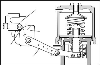
The positioner schematic (Figure 1) shows an XL Series positioner connected for double-acting service on a linear actuator. Tension on the feedback spring provides feedback to the positioner, which varies as the stem position changes. The spring-loading force is applied through the feedback linkage and cam to the positioner’s input capsule.
Instrument signal pressure is applied between the diaphragms in the input capsule. Therefore, the input capsule serves as a force-balance member, matching the valve stem position (as measured by tension on the feedback spring) to the instrument signal.
When the opposing forces balance exactly, the system will be in equilibrium and the stem will be in the exact position called for by the instrument signal. If the opposing forces are not in balance, the input capsule will move up or down and, by means of the pilot-valves, will
Valtek No. 10077320 |
45-1 |

Supply Seat |
|
|
Cylinder |
|
|
|
|
Upper Pilot |
Balance Adjustment |
Zero Adjustment |
|
|
Range |
||
Poppet |
|
|
|
|
|
Adjust Screw |
|
Exhaust Seat |
|
|
|
|
|
|
|
Port No. 1 |
|
|
Piston |
|
|
|
|
Restriction |
|
Feedback |
Cam |
|
|
|
|
Supply |
|
Spring |
Follower |
|
|
||
Pilot Valve |
|
Detecting |
Arm |
|
Nozzle |
|
|
Capsule |
|
|
|
|
|
|
|
Exhaust Seat |
|
|
O |
|
Flapper |
||
Port No. 2 |
|
|
Upper Diaphragm |
|
|
|
|
Lower Pilot |
|
|
S |
|
|
Instrument Signal |
|
Poppet |
|
|
|
|
|
Lower Diaphragm |
|
Supply Seat |
|
|
|
|
Input Capsule |
Take-off Arm |
|
|
|
|
|
Figure 1: XL Positioner Schematic for Air-to-Open
change the output pressures, moving the stem until the tension on the feedback spring opposes exactly the instrument signal pressure.
The sequence of operation is as follows: An increase in instrument signal pressure forces the input capsule downward. Displacement of the capsule in turn moves the flapper away from the detecting nozzle. This allows a larger flow rate through the nozzle, decreasing the pressure exerted on the top of the pilot valve capsule. Supply air biases the pilot-valve in an upward direction. As the capsule moves up, it will close the exhaust seat of the upper pilot poppet and open the supply seat, which applies increased air pressure to the bottom cylinder port. At the same time, the pilot-valve capsule will open the exhaust seat for the lower pilot poppet; thus, decreasing pressure to the top cylinder port.
This difference in pressure will drive the piston upward, which stretches the feedback spring until the spring tension exactly opposes the force resulting from the instrument signal pressure. At this point, the flapper will be moved toward the detecting nozzle to restore the pressure above the pilot-valve capsule to its equilibrium value. As a force-balanced condition is approached, the pilot-valve capsule will be forced back to a neutral position where the pilots are neither supplying air to, nor exhausting air from, their respective sides of the piston. A decrease in instrument signal pressure reverses the described actions and causes a proportional downward movement of actuator piston and stem.
Installation of XL Series Positioner on Double-Acting, Linear-Cylinder Actuators
When installing or retrofitting the XL Series positioner on all sizes of linear actuators, proceed as follows:
NOTE: For retrofitting to an actuator equipped with a Beta or 80R positioner, the same bracket, follower arm and take-off arm can be used (begin with step 4).
Size 25, 100, 200 |
Size 50 |
Figure 2: Positioner Mounting Bracket
Return Spring |
|
Hole |
|
A |
|
Cam |
|
|
Hole B |
Positioner |
|
Base |
|
Air-to-Open |
Air-to-Close |
(Air-to-Retract) |
(Air-to-Extend) |
Figure 3: Return Spring / Cam Mounting
(viewed from positioner’s right side)
45-2 |
Flowserve Corporation, Valtek Control Products, Tel. USA 801 489 8611 |
Roller |
Bearing |
Cam |
Cam |
Start |
Position |
Follower Arm |
Figure 4: Cam Alignment
NOTE: When retrofitting the XL positioner to an actuator equipped with other positioners, remove the existing positioner, tubing and associated bolting. See tubing instructions in Step 10.
1.Place the stem clamp onto the actuator stem with the boss on the right side as illustrated in Figure 1.
2.Mount positioner bracket to the yoke leg which has the stroke indicator plate attached. (See Figure 2.)
3.Mount the take-off arm on the stem clamp so the slots in the end of the arm step upward toward the cylinder. The holes in the follower arm should line up with the slots in the take-off arm.
4.For air-to-retract action, install the cam in the positioner, with L-R facing outward. For air-to-extend action, L-D side of the cam should face outward. When installing the cam, position it so the center mark on the cam lines up through the center of the cam roller-bearing on the cam follower arm with the follower arm perpendicular to the base of the positioner. (See Figures 3 and 4.) Apply a small amount of grease to the bent end of the return spring and feed it through the hole in the cam. Loop the other end of the return spring over the screw and screw it into the positioner base.
NOTE: Screw head will not bottom out.
5.Feed the appropriate follower arm onto the cam shaft boss with the hole markings facing outward. Secure with the lockwasher and nut. (See Figure 7.)
6.Fasten the follower pin into the correct hole in the follower arm for the desired stroke length of the trim. (Stroke lengths are stamped on the follower arm.)
7. Feed the follower pin into the appropriate slot in the take-off arm. (See Figure 4.) Tighten the nut on the pin and grease the slot where the pin rides.
NOTE: A light industrial grease is recommended. Failure to lubricate the pin can cause premature wear.
8.Using three screws, mount the positioner to the brackets as shown in Figure 2.
9.If necessary, adjust the height of the stem clamp so the first line of the cam aligns with the center of the
Flowserve Corporation, Valtek Control Products, Tel. USA 801 489 8611
cam roller-bearing when the valve is seated. (See Figure 4.) Tighten the stem clamp.
10.For air-to-open action, tube ‘output 2’ to the top of cylinder and ‘output 1’ to the bottom of cylinder. For air-to-close action, tube ‘output 1’ to top of cylinder and ‘output 2’ to the bottom of the cylinder.
NOTE: For three-way diaphragm actuators plug output 2, tube output 1 to desired side of diaphragm.
11.Attach supply air and instrument tubing or wiring.
CAUTION: Signal air pressure higher than 30 psi may damage the module gauge and instrument signal capsule; a 3-15 psi instrument signal is recommended on the pneumatic module.
Reversing Air Action of XL Series Positioners on Linear Actuators
Reversing the air-action of the positioner is simple. No additional parts are required, although the tubing will need to be rerouted on the linear actuator.
To reverse the air-action of XL series positioners on all sizes of linear actuators, proceed as follows:
1.Using the ‘Spring Cylinder Linear Actuators’ Installation, Operation, Maintenance Instructions, reverse the air-action of the actuator.
2.Disengage the return spring from the cam and remove the cam from the cam shaft.
3.Reverse the cam, return spring and tubing for the desired air-action by referring to Steps 4-8 in the ‘Installation of XL Series Positioner on Linear Actuators’ section of these instructions.
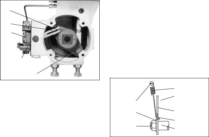
Installing XL Series Positioner on Rotary Actuators
Proceed as follows when installing the XL Series positioner on all sizes of rotary actuators if the cam and
follower arm are not already installed, otherwise refer directly to step 7.
1.With the desired cam and its identification letter facing toward the cam shaft, slide the cam onto the end of the cam shaft with the shorter shoulder. (Refer to Table I to determine desired cam characteristic.) Fasten with the star lock washer and nut.
2.Insert the follower arm into the back recess of the
Table I:
Rotary Actuator Cam Characteristic Chart
Valve Style |
Characteristic |
Air To |
||
|
|
|
|
|
SST/VLD |
Modified Equal |
Open |
Close |
|
Percentage |
B |
C |
||
|
||||
|
|
|
|
|
SST/VLD |
Linear |
C |
B |
|
|
|
|
|
|
|
Modified Equal |
CAM1 |
CAM2 |
|
MaxFlo |
Percentage |
|||
|
|
|||
|
Linear |
CAM1 |
CAM2 |
|
45-3
Follower
Pin
Follower
Arm
Cam
Read Cam Characteristics from this side only
Actuator Lever Arm
Figure 5: XL Series Positioner Installation on Valtek Rotary Actuator
positioner with part identification number facing out to the right side. Slide the cam shaft through the inner bearing and then slip flatted hole of the follower arm over the longer stepped shoulder of the cam shaft.
3.Place a small amount of thread-locking compound (Loctite No. 222 or equivalent) to the threaded portion of cam shaft nut. Slide the cam shaft nut through outer bearing and screw it onto the cam shaft. Tighten the cam shaft together firmly so that the follower arm is securely clamped. Also, make sure the cam is tightly secured to cam shaft. Check to be sure there is no slippage. Apply a small amount of grease to the bent end of the return spring and feed it through the hole in the cam. Loop the other end of the return spring over the screw and screw it into the positioner base.
NOTE: Screw head will not bottom out.
4.Rotate the zero adjustment arm back into place and reinstall the feedback spring.
5.If the follower pin is present, insert it into the hole in the actuator lever arm and drive it firmly into place with a hammer. (See Figure 5.)
6.Apply grease to the sliding surfaces of the follower arm before mounting the positioner to the transfer case. When mounting the positioner to the transfer case, make sure to guide the follower arm so the pin slides in the slot on the follower arm. (See Figure 5.) Fasten the positioner to the transfer case with the three mounting screws. Push up on the cam to verify the pin is riding in the follower arm slot or remove transfer case cover plate to inspect.
CAUTION: Failure to replace the cover plate before pressurizing or operating the actuator will cause damage to the shaft since the cover plate houses a shaft-support bearing.
Depending on the positioner cam side selected, the valve flow characteristic may be linear or equal percent when compared to the instrument signal to the
positioner. Figures 11 through 16 show the shaft rotation versus instrument signal of a valve (Valdisk, ShearStream or MaxFlo). These graphs should be used when visually checking the valve shaft rotation versus positioner signal relationship.
Reversing Air-Action of XL Series Positioners on Rotary Actuators
Reversing the action on rotary actuators is achieved by mounting the yoke to the opposite side of the transfer case. Refer to maintenance instructions ‘Spring Cylinder Rotary Actuators’ for details.
Note: When reversing action on rotary actuators, also change cam. (See Table I.)
|
Return Spring |
|
Read Cam |
Screw |
Characteristics |
from this side only |
|
Lock |
Cam |
Washer |
Grease Here |
|
|
Nut |
Cam Shaft |
|
Figure 6: Cam Return Spring Installation
POSITIONER CALIBRATION
Introduction
Valtek positioners are calibrated at the factory; however, due to shipping and handling, it may be necessary to check the calibration before operating the valve. The XL positioner, for strokes 3/4-inch and above, can be calibrated to a range of 3-15; two-way split range, 3-9, or 9-15; and three-way split ranging, 3-7, 7-11, 11-15 psi using the standard feedback spring. An alternate red colored feedback spring on linear actuators is used for strokes less than 3/4-inch.
WARNING: When stroking the actuator during calibration, keep hands, hair and clothing away from moving parts. Failure to do so may cause serious personal injury.
Note: Positioners and I/Ps are calibrated at the factory. Use mechanical adjustments in positioner for calibration. Zero and span on the I/P should not be used to calibrate valve.
For calibration, proceed as follows:
1.For 3-15 or 3-9 psi range, loosen by hand the zero adjustment locking knob and adjust the zero adjustment knob until the valve begins to stroke with more than 3 psi signal (for 9-15 psi range adjust to 9 psi).
2.Loosen the range adjustment locking screw no more than 1/8 turn.
45-4 |
Flowserve Corporation, Valtek Control Products, Tel. USA 801 489 8611 |
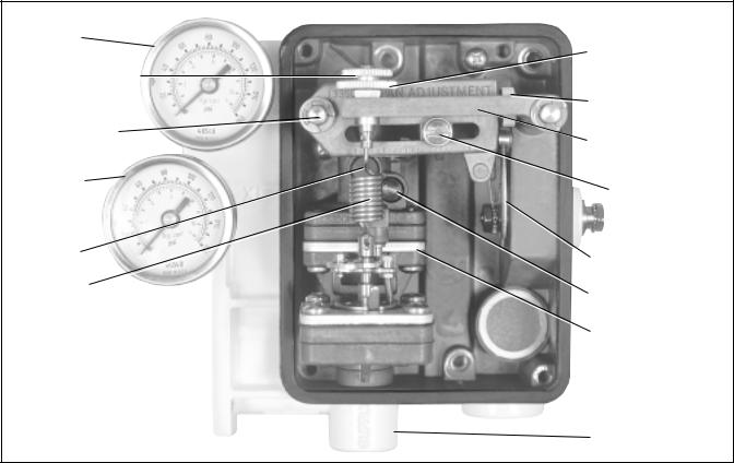
Output 1
Zero Adjustment
Lock Knob
Zero Adjustment
Knob
Span Adjustment
Cam Follower
Arm (Range Arm)
Feedback Spring
Arm
Output 2
Span
Balance
Adjustment
Adjusting
Locking Screw
Screw
Cam
Feedback
Orifice Screw
Spring
Pilot Relay
Assembly
Supply Port
Figure 7: Positioner Adjustments
3.With a Phillips screwdriver adjust span adjustment so valve is at full stroke with more than 15 psi for 3-15 or 9-15 psi range (adjust to 9 psi for 3-9 psi range).
4.Return to 3 psi (or 9 psi for 9-15 psi range) and check the zero. Repeat steps 1-4 if necessary.
5.Tighten the zero adjustment lock knob and span adjustment lock knob.
6.Use the same procedure for three-way split range.
Positioner Balance Adjustment
CAUTION: Balance is preset at the factory. If balance adjustment becomes necessary, make changes carefully and slowly, allowing the positioner to respond before continuing adjustments. Check balance pressure frequently to ensure correct values.
Balance adjustment is set at the factory and normally should not need adjustment. Balance adjustment (output pressure level) permits the equilibrium pressure in both sides of the actuator piston to be raised or lowered. The actuator pressure level of output 1 and 2 should be approximately 75 to 80 percent of the supply pressure. When actuator springs are used there will be a pressure difference between output 1 and 2; the average pressure of both ports should be 75 to 80 percent of the supply pressure. The minimum recommended supply pressure is 60 psig. For example, if 100 psig supply pressure was used on a fail closed actuator, the balance pressure should be adjusted so that output 1 reads approximately 85 psig and output pressure 2
reads approximately 70 psig. The average of these two pressures is 77.5 percent of the supply pressure.
If necessary, adjust the output pressure level using the following the procedure:
1.If output pressure level is low, before adjusting, check for leaks in tubing connections between the positioner and actuator and check supply pressure.
2.Make certain there is no process force or pressure in the valve (The valve should be removed or isolated from the process.)
3.On positioners without gauges, connect gauges to ‘output 1’ and ‘output 2’ lines.
4.Remove rubber cap over balance adjustment. (See Figure 7.)
5.Apply full actuator operating pressure to the positioner supply port.
6.Set input signal to midscale (9 psi for 3-15 psi span). Output pressure level cannot be adjusted with actuator against valve seat or travel stops. Allow actuator pressure to stabilize.
7.Observe the pressure gauges. If reading is not correct, turn balance adjustment screw about 1/8 turn at a time and wait about 20-30 seconds for pressure to stabilize (counterclockwise to increase pressure). Continue until output pressure level of the higher pressure gauge is approximately 80 percent of supply.
8.Replace rubber cap over balance adjustment screw.
Flowserve Corporation, Valtek Control Products, Tel. USA 801 489 8611 |
45-5 |
 Loading...