


®
Pump Division
Type: WDX
CENTRIFUGAL PUMPS
USER INSTRUCTIONS:
INSTALLATION, OPERATION, MAINTENANCE
PCN=71576322 06-05 (E)
 These instructions must be read prior to installing, operating, using and maintaining this equipment.

WDX USER INSTRUCTIONS ENGLISH 71576322 06-05
®
CONTENTS
|
|
PAGE |
|
PAGE |
|
1 INTRODUCTION AND SAFETY .......................... |
4 |
6 MAINTENANCE................................................ |
28 |
||
1.1 General....................................................... |
4 |
6.1 General..................................................... |
28 |
||
1.2 |
CE marking and approvals........................... |
4 |
6.2 Maintenance schedule............................... |
28 |
|
1.3 |
Disclaimer................................................... |
4 |
6.3 Spare parts................................................ |
31 |
|
1.4 |
Copyright .................................................... |
4 |
6.4 Recommended spares and consumable.......... |
|
|
1.5 |
Duty conditions............................................ |
4 |
items.............................................................. |
32 |
|
1.6 Safety......................................................... |
5 |
6.5 Tools required............................................ |
32 |
||
1.7 Safety labels summary................................. |
8 |
6.6 Fastener torques ....................................... |
32 |
||
1.8 Specific machine performance...................... |
8 |
6.7 Renewal clearances .................................. |
32 |
||
1.9 |
Noise level.................................................. |
9 |
6.8 Disassembly.............................................. |
32 |
|
2 TRANSPORT AND STORAGE |
10 |
6.9 Inspection of components........................... |
36 |
||
6.10 Assembly |
37 |
||||
2.1 |
Consignment receipt and unpacking |
10 |
|||
7 FAULTS; CAUSES AND REMEDIES |
38 |
||||
2.2 |
Handling |
10 |
|||
|
|
||||
2.3 |
Lifting........................................................ |
11 |
8 PARTS LISTS AND DRAWINGS |
40 |
|
2.4 Storage |
12 |
||||
|
|
||||
2.5 |
Recycling and end of product life................ |
12 |
8.1 Sectional drawings, WDXR grease lubricated |
||
3 PUMP DESCRIPTION |
12 |
uncooled ........................................................ |
40 |
||
8.2 Sectional drawings, variants |
41 |
||||
|
|
|
|||
3.1 |
Configurations........................................... |
12 |
8.3 Sectional drawings, other details ................ |
42 |
|
3.2 |
Nomenclature............................................ |
13 |
8.4 Sectional drawings part list......................... |
43 |
|
3.3 |
Design of major parts................................. |
13 |
8.5 General arrangement drawing.................... |
45 |
|
3.4 |
Materials of construction ............................ |
14 |
9 CERTIFICATION |
45 |
|
3.5 |
Performance and operating limits |
14 |
|||
|
|
||||
3.6 |
Coverage charts........................................ |
15 |
10 OTHER RELEVANT DOCUMENTATION AND |
||
|
|
|
|||
4 INSTALLATION................................................. |
16 |
MANUALS.................................................... |
45 |
||
4.1 |
Location.................................................... |
16 |
10.1 Supplementary User Instructions .............. |
45 |
|
4.2 |
Cleaning prior to installation ....................... |
16 |
10.2 Change notes.......................................... |
45 |
|
4.3 |
Foundation................................................ |
16 |
10.3 Additional sources of information .............. |
45 |
|
4.4 Grouting.................................................... |
17 |
|
|
||
4.5 |
Initial alignment ......................................... |
17 |
|
|
|
4.6 |
Piping ....................................................... |
18 |
|
|
|
4.7 |
Final shaft alignment check........................ |
21 |
|
|
|
4.8 |
Electrical connections ................................ |
21 |
|
|
|
4.9 Protection systems .................................... |
22 |
|
|
||
5 COMMISSIONING, START-UP, OPERATION AND |
|
|
|||
SHUTDOWN................................................ |
22 |
|
|
||
5.1 Pre-commissioning procedure.................... |
22 |
|
|
||
5.2 Pump lubricants......................................... |
23 |
|
|
||
5.3 |
Direction of rotation.................................... |
24 |
|
|
|
5.4 Guarding................................................... |
24 |
|
|
||
5.5 |
Priming and auxiliary supplies .................... |
24 |
|
|
|
5.6 Starting the pump ...................................... |
25 |
|
|
||
5.7 |
Running the pump ..................................... |
25 |
|
|
|
5.8 Stopping and shutdown.............................. |
27 |
|
|
||
5.9 |
Hydraulic, mechanical and electrical duty.... |
27 |
|
|
|
5.10 Pumps for Food Use or Potable Water...... |
27 |
|
|
||
Page 2 of 46

WDX USER INSTRUCTIONS ENGLISH 71576322 06-05
®
INDEX
PAGE |
PAGE |
Additional sources (10.3)...................................... |
45 |
Alignment of shafting (see 4.3, 4.5 and 4.7) |
|
Assembly (6.10)................................................... |
37 |
ATEX marking (1.6.4.2).......................................... |
7 |
CE marking and approvals (1.2).............................. |
4 |
Certification (9).................................................... |
45 |
Change notes (10.2)............................................ |
45 |
Clearances (see 6.7, Renewal clearances)............ |
32 |
Commissioning, start-up, operation (5).................. |
22 |
Compliance, ATEX (1.6.4.1)................................... |
6 |
Configurations (3.1) ............................................. |
12 |
Copyright (1.4)....................................................... |
4 |
Coverage charts (3.6) .......................................... |
15 |
Design of major parts (3.3)................................... |
13 |
Direction of rotation (5.3)...................................... |
24 |
Disassembly (6.8)................................................ |
32 |
Disclaimer (1.3)..................................................... |
4 |
Dismantling (see 6.8, Disassembly) ...................... |
32 |
Drawings (8)........................................................ |
40 |
Duty conditions (1.5).............................................. |
4 |
Electrical connections (4.8)................................... |
21 |
End of product life (2.5)........................................ |
12 |
Inspection of components (6.9)............................. |
36 |
Fastener torques (6.6).......................................... |
32 |
Faults; causes and remedies (7)........................... |
38 |
Foundation (4.3).................................................. |
16 |
Forces and moments (4.6.3)................................. |
20 |
General arrangement drawing (8.5)....................... |
45 |
Grouting (4.4)...................................................... |
17 |
Guarding (5.4)..................................................... |
24 |
Handling (2.2)...................................................... |
10 |
Hydraulic, mechanical and electrical duty (5.9) ...... |
27 |
Inspection (6.2.1 and 6.2.2).................................. |
29 |
Installation (4)...................................................... |
16 |
Lifting (2.3).......................................................... |
11 |
Location (4.1)...................................................... |
16 |
Lubrication (see 5.1.1, 5.2 and 6.2.3) |
|
Lubrication schedule (5.2.4).................................. |
24 |
Maintenance (6)................................................... |
28 |
Maintenance schedule (6.2).................................. |
28 |
Nomenclature (3.2).............................................. |
13 |
Nameplate (1.7.1).................................................. |
8 |
Operating limits (3.5.1)......................................... |
14 |
Ordering spare parts (6.3.1).................................. |
31 |
Parts lists (8.4) .................................................... |
43 |
Performance (3.5)................................................ |
14 |
Piping (4.6).......................................................... |
18 |
Pre-commissioning (5.1)....................................... |
22 |
Protection systems (4.9)....................................... |
22 |
Pump masses (2.2.2)........................................... |
11 |
Reassembly (see 6.10, Assembly)........................ |
37 |
Receipt and unpacking (2.1)................................. |
10 |
Recommended fill quantities (see 5.2.3)................ |
23 |
Recommended grease lubricants (5.2.2)............... |
23 |
Recommended oil lubricants (5.2.1)...................... |
23 |
Recommended spares (6.4)................................. |
32 |
Recycling (2.5) .................................................... |
12 |
Replacement parts (see 6.3 and 6.4)..................... |
31 |
Running the pump (5.7)........................................ |
25 |
Safety action (1.6.3)............................................... |
5 |
Safety markings (1.6.1).......................................... |
5 |
Safety, protection systems (see 1.6 and 4.9) |
|
Sectional drawings (8.1)....................................... |
40 |
Sound level (see 1.9, Noise level)........................... |
9 |
Sources, additional information (10.3)................... |
45 |
Spare parts (6.3).................................................. |
31 |
Specific machine performance (1.8)........................ |
8 |
Starting the pump (5.6)......................................... |
25 |
Stop/start frequency (5.7.6).................................. |
26 |
Stopping and shutdown (5.8)................................ |
27 |
Storage, pump (2.4)............................................. |
12 |
Storage, spare parts (6.3.2).................................. |
32 |
Supplementary manuals or information sources..... |
45 |
Thermal expansion (4.5.1).................................... |
17 |
Tools required (6.5).............................................. |
32 |
Torques for fasteners (6.6)................................... |
32 |
Transport (2) ....................................................... |
10 |
Trouble-shooting (see 7)...................................... |
38 |
Vibration (5.7.5)................................................... |
26 |
Warning labels (1.7.2)............................................ |
8 |
Page 3 of 46

WDX USER INSTRUCTIONS ENGLISH 71576322 06-05
®
1 INTRODUCTION AND SAFETY
1.1 General
 These instructions must always be kept close to the product's operating location or directly with the product.
Flowserve products are designed, developed and manufactured with state-of-the-art technologies in modern facilities. The unit is produced with great care and commitment to continuous quality control, utilizing sophisticated quality techniques, and safety requirements.
Flowserve is committed to continuous quality improvement and being at service for any further information about the product in its installation and operation or about its support products, repair and diagnostic services.
These instructions are intended to facilitate familiarization with the product and its permitted use. Operating the product in compliance with these instructions is important to help ensure reliability in service and avoid risks. The instructions may not take into account local regulations; ensure such regulations are observed by all, including those installing the product. Always coordinate repair activity with operations personnel, and follow all plant safety requirements and applicable safety and health laws and regulations.
 These instructions must be read prior to installing, operating, using and maintaining the equipment in any region worldwide. The equipment must not be put into service until all the conditions relating to safety noted in the instructions, have been met.
1.2 CE marking and approvals
It is a legal requirement that machinery and equipment put into service within certain regions of the world shall conform with the applicable CE Marking Directives covering Machinery and, where applicable, Low Voltage Equipment, Electromagnetic Compatibility (EMC), Pressure Equipment Directive (PED) and Equipment for Potentially Explosive Atmospheres
(ATEX).
Where applicable the Directives and any additional Approvals coverimportant safety aspects relating to machinery and equipment and the satisfactory provision of technical documents and safety instructions. Where applicable this document incorporates information relevant to these Directives and Approvals.
To confirm the Approvals applying and if the product is CE marked, check the serial number plate markings and the Certification. (See section 9, Certification.)
1.3 Disclaimer
Information in these User Instructions is believed to be reliable. In spite of all the efforts of Flowserve Pump Division to provide sound and all necessary information the content of this manual may appear insufficient and is not guaranteed by Flowserve as to its completeness or accuracy.
Flowserve manufactures products to exacting International Quality Management System Standards as certified and audited by external Quality Assurance organizations. Genuine parts and accessories have been designed, tested and incorporated into the products to help ensure their continued product quality and performance in use. As Flowserve cannot test parts and accessories sourced from other vendors the incorrect incorporation of such parts and accessories may adversely affect the performance and safety features of the products. The failure to properly select, install or use authorized Flowserve parts and accessories is considered to be misuse. Damage or failure caused by misuse is not covered by the Flowserve warranty. In addition, any modification of Flowserve products or removal of original components may impair the safety of these products in their use.
1.4 Copyright
All rights reserved. No part of these instructions may be reproduced, stored in a retrieval system or transmitted in any form or by any means without prior permission of Flowserve Pump Division.
1.5 Duty conditions
This product has been selected to meet the specifications of your purchaser order. The acknowledgement of these conditions has been sent separately to the Purchaser. A copy should be kept with these instructions.
 The product must not be operated beyond the parameters specified for the application. If there is any doubt as to the suitability of the product for the application intended, contact Flowserve for advice, quoting the serial number.
If the conditions of service on your purchase order are going to be changed (for example liquid pumped, temperature or duty) it is requested that the user seeks the written agreement of Flowserve before start up.
Page 4 of 46

WDX USER INSTRUCTIONS ENGLISH 71576322 06-05
®
1.6 Safety
1.6.1 Summary of safety markings
These User Instructions contain specific safety markings where non-observance of an instruction would cause hazards. The specific safety markings are:
 This symbol indicates electrical safety instructions where non-compliance will involve a high risk to personal safety or the loss of life.
 This symbol indicates safety instructions where non-compliance would affect personal safety and could result in loss of life.


 Thissymbolindicates“hazardoussubstancesand toxicfluid”safetyinstructions where non-compliance would affect personal safety and could result in loss of life.
 This symbol indicates safety instructions where non-compliance will involve some risk to safe operation and personal safety and would damage the equipment or property.
 This symbol indicates explosive atmosphere zone marking according to ATEX. It is used in safety instructions where non-compliance in the hazardous area would cause the risk of an explosion.
 This symbol is used in safety instructions to remind not to rub non-metallic surfaces with a dry cloth; ensure cloth is damp. It is used where noncompliance in the hazardous area would cause the risk of an explosion.
 This sign is not a safety symbol but indicates an important instruction in the assembly process.
1.6.2 Personnel qualification and training
All personnel involved in the operation, installation, inspection and maintenance of the unit must be qualified to carry out the work involved. If the personnel in question do not already posse ss the necessary knowledge and skill, appropriate training and instruction must be provided. If required the operator may commission the manufacturer/supplier to provide applicable training.
Always coordinate repair activity with operations and health and safety personnel, and follow all plant safety requirements and applicable safety and health laws and regulations.
1.6.3 Safety action
This is a summary of conditions and actions to prevent injury to personnel and damage to the environment and to equipment. For products used in potentially explosive atmospheres section 1.6.4 also applies.
 NEVER DO MAINTENANCE WORK WHEN THE UNIT IS CONNECTED TO POWER
 GUARDS MUST NOT BE REMOVED WHILE THE PUMP IS OPERATIONAL
 DRAIN THE PUMP AND ISOLATE PIPEWORK BEFORE DISMANTLING THE PUMP
The appropriate safety precautions should be taken where the pumped liquids are hazardous.
 FLUORO-ELASTOMERS (When fitted.)
When a pump has experienced temperatures over 250 ºC (482 ºF), partial decomposition of fluoro-elastomers (example: Viton) will occur. In this condition these are extremely dangerous and skin contact must be avoided.
 HANDLING COMPONENTS
Many precision parts have sharp corners and the wearing of appropriate safety gloves and equipment is required when handling these components. To lift heavy pieces above 25 kg (55 lb) use a crane appropriate for the mass and in accordance with current local regulations.
 THERMAL SHOCK
Rapid changes in the temperature of the liquid within the pump can cause thermal shock, which can result in damage or breakage of components and should be avoided.
 NEVER APPLY HEAT TO REMOVE IMPELLER Trapped lubricant or vapour could cause an explosion.
 HOT (and cold) PARTS
If hot or freezing components or auxiliary heating supplies can present a danger to operators and persons entering the immediate area action must be taken to avoid accidental contact. If complete protection is not possible, the machine access must be limited to maintenance staff only, with clear visual warnings and indicators to those entering the immediate area. Note: bearing housings must not be insulated and drive motors and bearings may be hot.
If the temperature is greater than 68 °C (175 °F) or below 5 °C (20 °F) in a restricted zone, or exceeds local regulations, action as above shall be taken.
Page 5 of 46

WDX USER INSTRUCTIONS ENGLISH 71576322 06-05
®


 HAZARDOUS LIQUIDS
When the pump is handling hazardous liquids care must be taken to avoid exposure to the liquid by appropriate sitting of the pump, limiting personnel access and by operator training. If the liquid is flammable and/or explosive, strict safety procedures must be applied.
Gland packing must not be used when pumping hazardous liquids.
 PREVENT EXCESSIVE EXTERNAL PIPE LOAD
Do not use pump as a support for piping. Do not mount expansion joints, unless allowed by Flowserve in writing, so that their force, due to internal pressure, acts on the pump flange.
 ENSURE CORRECT LUBRICATION (See section 5, Commissioning, startup, operation and shutdown.)
 START THE PUMP WITH OUTLET VALVE PART OPENED
(Unless otherwise instructed at a specific point in the User Instructions.)
This is recommended to minimize the risk of overloading and damaging the pump motor at full or zero flow. Pumps may be started with the valve further open only on installations where this situation cannot occur. Pump outlet valve shall may need to be adjusted to comply with the duty following the run-up process. (See section 5, Commissioning start-up, operation and shutdown.)
 NEVER RUN THE PUMP DRY
 INLET VALVES TO BE FULLY OPEN WHEN PUMP IS RUNNING
Running the pump at zero flow or below the recommended minimum flow continuously will cause damage to the seal.
 DO NOT RUN THE PUMP AT ABNORMALLY HIGH OR LOW FLOW RATES Operating at a flow rate higher than normal or at a flow rate with no backpressure on the pump may overload the motor and cause cavitations. Low flow rates may cause a reduction in pump/bearing life, overheating of the pump, instability and cavitations/vibration.
1.6.4 Products used in potentially explosive atmospheres
 Measures are required to:
Avoid excess temperature.
Prevent build up of explosive mixtures.
Prevent the generation of sparks.
Prevent leakages.
Maintain the pump to avoid hazard.
The following instructions for pumps and pump units when installed in potentially explosive atmospheres must be followed to help ensure explosion protection. Both electrical and non-electrical equipment must meet the requirements of European Directive 94/9/EC.
1.6.4.1 Scope of compliance
 Use equipment only in the zone for which it is appropriate. Always check that the driver, drive coupling assembly, seal and pump equipment are suitably rated and/or certified for the classification of the specific atmosphere in which they are to be installed.
Where Flowserve has supplied only the bare shaft pump, the Ex rating applies only to the pump. The party responsible for assembling the pump set shall select the coupling, driver and any additional equipment, with the necessary CE Declaration of Conformity establishing it is suitable for the area in which it is to be installed.
The output from a variable frequency drive (VFD) can cause additional heating affects in the motor and so, for pumps sets with a VFD, the ATEX Certification for the motor must state that it is covers the situation where electrical supply is from the VFD. This particular requirement still applies even if the VFDis in a safe area.
Page 6 of 46
WDX USER INSTRUCTIONS ENGLISH 71576322 06-05
®
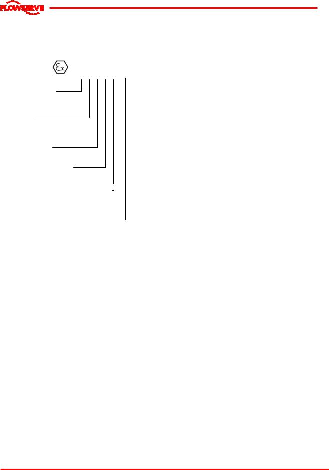
1.6.4.2 Marking
An example of ATEX equipment marking is shown below. The actual classification of the pump will be engraved on the nameplate.
II 2 GD c IIC 135 ºC (T4)
Equipment Group
I = Mining
II = Non-mining
Category
2or M2 = High level protection
3= normal level of protection
Gas and/or Dust
G = Gas; D= Dust
c = Constructional safety
(in accordance with prEn13463-5)
Gas Group (Equipment Category 2 only)
IIA –Propane (typical)
IIB –Ethylene (typical)
IIC –Hydrogen (typical)
Maximum surface temperature (Temperature Class) (see section 1.6.4.3)
1.6.4.3 Avoiding excessive surface temperatures
 ENSURE THE EQUIPMENT TEMPERATURE CLASS IS SUITABLE FOR THE HAZARD ZONE
Pumps have a temperature class a s stated in the ATEX Ex rating on the nameplate. These are based on a maximum ambient of 40 °C (104 °F); refer to Flowserve for higher ambient temperatures.
The surface temperature on the pump is influenced by the temperature of the liquid handled. The maximum permissible liquid temperature depends on the temperature class and must not exceed the values in the table that follows.
The temperature rise at the seals, bearings and due to the minimum permitted flow rate is taken into account in the temperatures stated.
|
Maxi mum |
Temperature limit of liquid |
||
Temperature |
handled (* dependi ng on |
|||
|
surface |
|||
class to |
temperature |
material and c onstruc tion |
||
prEN 13463-1 |
permitted |
variant - c hec k whic h is |
||
|
|
|
lower) |
|
T6 |
85 °C (185 °F) |
Consult Flows erve |
||
T5 |
100 |
°C (212 °F) |
Consult Flows erve |
|
T4 |
135 |
°C (275 °F) |
115 °C (239 °F) * |
|
T3 |
200 |
°C (392 °F) |
180 °C (356 °F) * |
|
T2 |
300 |
°C (572 °F) |
275 °C (527 °F) * |
|
T1 |
450 |
°C (842 °F) |
400 °C (752 °F) * |
|
The responsibility for compliance with the specified maximum liquid temperature is with the plant operator.
Temperatureclassification“Tx”isusedwhentheliquid temperature varies and the pump could be installed in different hazardous atmospheres. In this case the user is responsible for ensuring that the pump surface temperature does not exceed that permitted in the particular hazardous atmosphere.
If an explosive atmosphere exists during the installation, do not attempt to check the direction of rotation by starting the pump unfilled. Even a short run time may give a high temperature resulting from contact between rotating and stationary components.
Where there is any risk of the pump being run against a closed valve generating high liquid and casing external surface temperaturesit is recommended that users fit an external surface temperature protection device.
Avoid mechanical, hydraulic or electrical overload by using motor overload trips, temperature monitor or a power monitor and make routine vibration monitoring checks.
In dirty or dusty environments, regular checks must be made and dirt removed from areas around close clearances, bearing housings and motors.
1.6.4.4 Preventing the build up of explosive mixtures
 ENSURE PUMP IS PROPERLY FILLED AND VENTED AND DOES NOT RUN DRY.
Ensure pump and relevant suction and discharge pipeline system is totally filled with liquid at all times during the pump operation, so that an explosive atmosphere is prevented. In addition it is essential to make sure that seal chambers, auxiliary shaft seal systems and any heating and cooling systems are properly filled.
If the operation of the system cannot avoid this condition the fitting of an appropriate dry run protection device is recommended (eg liquid detection or power monitor).
To avoid potential hazards from fugitive emissions of vapour or gas to atmosphere the surrounding area must be well ventilated.
Page 7 of 46
WDX USER INSTRUCTIONS ENGLISH 71576322 06-05
®
1.6.4.5 Preventing sparks
 To prevent a potential hazard from mechanical contact, the coupling guard must be non-sparking. To avoid the potential hazard from random induced current generating a spark the ground contact on the baseplate must be used.
 Avoid electrostatic charge: do not rub nonmetallic surfaces with a dry cloth, ensure cloth is damp.
The coupling must be selected to comply with 94/9/EC and correct alignment must be maintained.
Additional requirements for metallic pumps on
non-metallic baseplates
When metallic components are fitted on a non-metallic baseplate they must be individually earthed.
1.6.4.6 Preventing leakage
 The pump must only be used to handle liquids for which it has been approved to have the correct corrosion resistance.
Avoid entrapment of liquid in the pump and associated piping due to closing of suction and discharge valves, which could cause dangerous excessive pressures to occur if there is heat input to the liquid. This can occur if the pump is stationary or running.
Bursting of liquid containing parts due to freezing must be avoided by draining or protecting the pump and ancillary systems.
Where there is the potential hazard of a loss of a seal barrier fluid or external flush, the fluid must be monitored.
If leakage of liquid to atmosphere can result in a hazard, the installation of a liquid detection device is recommended.
1.6.4.7 Maintenance to avoid the hazard
 CORRECT MAINTENANCE IS REQUIRED TO AVOID POTENTIAL HAZARDS WHICH GIVE A RISK OF EXPLOSION
The responsibility for compliance with maintenance instructions is with the plant operator.
To avoid potential explosion hazards during maintenance, the tools, cleaning and painting materials used must not give rise to sparking or adversely affect the ambient conditions.
Where there is a risk from such tools or materials; maintenance must be conducted in a safe area. It is recommended that a maintenance plan and schedule is adopted. (See section 6, Maintenance.)
1.7 Safety labels summary
1.7.1 Nameplate
For details of nameplate, see the Declaration of Conformity, or separate documentation included with these User Instructions.
1.7.2 Warning labels
Oil lubricated units only:
1.8 Specific machine performance
For performance parameters see section 1.5, Duty conditions. When the contract requirement specifies these to be incorporated into User Instructions these are included here. Where performance data has been supplied separately to the purchaser these should be obtained and retained with these User Instructions if required.
Page 8 of 46

WDX USER INSTRUCTIONS ENGLISH 71576322 06-05
®
1.9 Noise le vel
When pump noise level exceeds 85dBA attention must be given to prevailing Health and Safety Legislation, to limit the exposure of plant operating personnel to the noise. The usual approach is to control exposure time to the noise or to enclose the machine to reduce emitted sound. You may have already specified a limiting noise level when the equipment was ordered, however if no noise requirements were defined then machines above a certain power level will exceed 85 dB(A). In such situations consideration must be given to the fitting of an acoustic enclosure to meet local regulations.
Pump noise level is dependent on a number of factors - the type of motor fitted, the operating capacity, pipework design and acoustic characteristics of the building. Typical sound pressure levels measured in dB and A-weighted are shown in the table below.
The figures are indicative only, they are subject to a +3 dB tolerance, and cannot be guaranteed.
The values are based on the noisiest ungeared electric motors which are likely to be encountered. They are LpA sound pressure levels at 1m (3.3ft) from the directly driven pump, for "free field over a reflecting plane". For estimating LwA sound power level (re 1 pW) add 14 dB(A) to the sound pressure value.
If a pump only has been purchased, for fitting with your own driver, then the "pump only" noise levels from the table should be combined with the level for the driver obtained from the supplier. If the motor is driven by an inverter, it may show an increase in noise level at some speeds. Consult a Noise Specialist for this calculation
For units driven by equipment other than
electric motors or units contained within enclosures, see the accompanying information sheets and manuals.
Typical sound pressure level, dBA, LpA at1mreference20μPa(LwA sound power1 pW where LpA >85 dBA)
Motor size |
|
3550 r/m in |
2900 r/m in |
1750 r/m in |
1450 r/m in |
||||||
and speed |
|
|
|
|
|
|
|
|
|
||
Pump and |
Pump |
Pump and |
Pump |
Pump and |
Pump |
Pump and |
Pump |
||||
|
|
||||||||||
kW (hp) |
motor |
onl y |
motor |
onl y |
motor |
onl y |
motor |
onl y |
|||
dBA |
dBA |
dBA |
dBA |
dBA |
dBA |
dBA |
dBA |
||||
|
|
|
|
|
|
|
|
|
|
|
|
5.5 |
(7.5) |
90 |
(99) |
77 |
83 |
73 |
76 |
73 |
72 |
71 |
|
|
|
|
|
|
|
|
|
|
|
||
7.5 (10) |
90 |
(99) |
78 |
83 |
74 |
77 |
74 |
73 |
72 |
||
|
|
|
|
|
|
|
|
|
|
||
11 |
(15) |
91 (100) |
80 |
84 |
76 |
78 |
76 |
74 |
73 |
||
15 |
(20) |
92 (101) |
83 |
85 (94) |
79 |
80 |
79 |
76 |
75 |
||
|
|
|
|
|
|
|
|
|
|||
18.5 (25) |
92 (101) |
83 |
85 (94) |
79 |
80 |
79 |
76 |
75 |
|||
|
|
|
|
|
|
|
|
|
|
||
22 |
(30) |
92 (101) |
83 |
85 (94) |
79 |
81 |
79 |
77 |
75 |
||
|
|
|
|
|
|
|
|
|
|
|
|
30 |
(40) |
100 |
(109) |
85 (94) |
93 (102) |
81 |
84 |
80 |
80 |
76 |
|
37 |
(50) |
100 |
(109) |
86 (95) |
93 (102) |
82 |
84 |
80 |
80 |
76 |
|
|
|
|
|
|
|
|
|
|
|
|
|
45 |
(60) |
100 |
(109) |
87 (96) |
93 (102) |
83 |
84 |
80 |
80 |
76 |
|
|
|
|
|
|
|
|
|
|
|
|
|
55 |
(75) |
100 |
(109) |
88 (97) |
95 (104) |
84 |
86 (95) |
81 |
82 |
77 |
|
75 (100) |
100 |
(109) |
90 (99) |
95 (104) |
86 (95) |
88 (97) |
81 |
83 |
78 |
||
|
|
|
|
|
|
|
|
|
|
||
90 (120) |
100 |
(109) |
90 (99) |
95 (104) |
86 (95) |
90 (99) |
81 |
85 (94) |
78 |
||
|
|
|
|
|
|
|
|
|
|
|
|
110 |
(150) |
100 |
(109) |
91 (100) |
95 (104) |
87 (96) |
91 (100) |
83 |
86 (95) |
79 |
|
150 |
(200) |
101 |
(110) |
92 (101) |
96 (105) |
88 (97) |
91 (100) |
83 |
86 (95) |
79 |
|
|
|
|
|
|
|
|
|
|
|
|
|
200 |
(270) |
|
* |
* |
* |
* |
* |
83 |
* |
80 |
|
|
|
|
|
|
|
|
|
|
|
|
|
300 |
(400) |
|
- |
- |
- |
- |
* |
84 |
* |
81 |
|
|
|
|
|
|
|
|
|
|
|
|
|
500 |
(670) |
|
- |
- |
- |
- |
* |
85 (94) |
* |
83 |
|
*Motors in this range are generall y job s pecific and nois e levels should be c alculated based on ac tual equipment installed. For 960 rpm reduce 1450 r pm values by 5 dBA.
Page 9 of 46

WDX USER INSTRUCTIONS ENGLISH 71576322 06-05
®
In areas where the staff has to intervene, remember that when the level of the sound pressure is:
Below 70 dBA :It is not necessary to take special precautions.
Each product has a unique serial number. Check that this number corresponds with that advised and always quote this number in correspondence as well as when ordering spare parts or further accessories.
Above 70 dBA :People working continuously in the machine room must be supplied with protective devices against noise.
Below 85 dBA :No particular measures need to be taken for casual visitors staying in the room during a limited period.
Above 85 dBA :The room must be considered as a dangerous area because of the noise and a warning sign must be fixed at each entry warning the people coming into the room, even for a short period, that they must wear hearing protection.
Above 105 dBA:Special hearing protection adapted to this noise level and to the spectral noise components must be installed and a warning sign to this effect erected at each entry.
The staff in the room must wear ear protection.
Make sure that the noise, which travels through the walls and windows, does not generate too high noise levels in the machine room's surroundings.
2.2 Handling
2.2.1 General instructions concerning handling
Boxes, crates, pallets or cartons may be unloaded using fork-lift vehicles or slings dependent on their size and construction. See 2.3.1 for positioning of slings.
To lift heavy pieces above 55 lb (25 kg), use a crane corresponding to the mass and in accordance with the current local regulations.
To lift machines or pieces with one or several lifting rings, only use hooks and chains in compliance with the local regulations concerning safety. Never put cables, chains or ropes directly on or in the lifting rings. Cables, chains or lifting ropes must never present excessive bending.
Never bend the lifting hooks, lifting rings, chains, etc... They are only made to endure stresse s within calculated limits. Remember that the capacity of a lifting device decreases when the direction of the lifting force direction makes an angle with the device axis.
To increase the safety and efficiency of the lifting device, all the lifting elements must be as perpendicular as possible. If necessary a lifting beam can be placed between the crane and the load.
2 TRANSPORT AND STORAGE
2.1 Consignment receipt and unpacking
Immediately after receipt of the equipment it must be checked against the delivery and shipping documents for its completeness and that there has been no damage in transportation.
Any shortage and or damage must be reported immediately to Flowserve Pump Division and received in writing within one month of receipt of the equipment. Later claims cannot be accepted.
Check any crate, boxes and wrappings for any accessories or spare parts that may be packed separately with the equipment or attached to side walls of the box or equipment.
When heavy pieces are lifted up, never stay or work under the load or in the area which could be in the path of the load if it were to swing or fall away. Never leave a load hanging from a crane. The acceleration or the deceleration of lifting equipment must stay in the safety limits for the staff.
A crane must be positioned in such a way that the load will be raised perpendicularly. Where possible necessary precautions must be taken to avoid the swing of the load. For example use two winches making approximately the same angle, less than 30°, with the vertical.
Page 10 of 46

WDX USER INSTRUCTIONS ENGLISH 71576322 06-05
®
2.2.2 Pump masses
All masses, in the table below, are for 3 stages, in construction M2.
|
|
|
MET PUMP MASS |
|
MASS |
|||||
PUMP |
|
|
|
|
|
|
|
PER |
||
|
WDX R/C |
WDX E |
WDX S |
|||||||
|
STAGE |
|||||||||
SIZE |
|
|||||||||
|
|
|
|
|
|
|
|
|
||
|
|
lb |
kg |
lb |
kg |
lb |
kg |
lb |
kg |
|
|
|
|
|
|
|
|
|
|
|
|
|
Non |
298 |
135 |
271 |
123 |
243 |
110 |
23 |
10.5 |
|
1.5WDX |
coole d |
|||||||||
|
|
|
|
|
|
|
|
|
||
Cool ed |
309 |
140 |
295 |
134 |
267 |
121 |
23 |
10.5 |
||
|
||||||||||
|
|
|
|
|
|
|
|
|
|
|
|
Non |
355 |
161 |
315 |
143 |
302 |
137 |
31 |
14 |
|
2WDX |
coole d |
|||||||||
|
|
|
|
|
|
|
|
|
||
Cool ed |
386 |
175 |
342 |
155 |
328 |
149 |
31 |
14 |
||
|
||||||||||
|
|
|
|
|
|
|
|
|
|
|
|
Non |
483 |
219 |
450 |
204 |
421 |
191 |
46 |
21 |
|
3WDX |
coole d |
|||||||||
|
|
|
|
|
|
|
|
|
||
Cool ed |
516 |
234 |
478 |
217 |
450 |
204 |
46 |
21 |
||
|
||||||||||
|
|
|
|
|
|
|
|
|
|
|
|
Non |
661 |
300 |
606 |
275 |
562 |
255 |
60 |
27 |
|
4WDX |
coole d |
|||||||||
|
|
|
|
|
|
|
|
|
||
Cool ed |
694 |
315 |
628 |
285 |
606 |
275 |
60 |
27 |
||
|
||||||||||
|
|
|
|
|
|
|
|
|
|
|
All masses, in the table below, are for 3 stages, in construction M3, M4, M5, M6, M7.
 To avoid distortion, the pump unit should be lifted as shown.
Motor pump unit
|
|
|
MET PUMP MASS |
|
MASS |
|||||
PUMP |
|
|
|
|
|
|
|
PER |
||
|
WDX R/C |
WDX E |
WDX S |
|||||||
|
STAGE |
|||||||||
SIZE |
|
|||||||||
|
|
|
|
|
|
|
|
|
||
|
|
lb |
kg |
lb |
kg |
lb |
kg |
lb |
kg |
|
|
|
|
|
|
|
|
|
|
|
|
|
Non |
324 |
147 |
298 |
135 |
260 |
118 |
25 |
11.5 |
|
1.5WDX |
coole d |
|||||||||
|
|
|
|
|
|
|
|
|
||
Cool ed |
335 |
152 |
322 |
146 |
293 |
133 |
25 |
11.5 |
||
|
||||||||||
|
|
|
|
|
|
|
|
|
|
|
|
Non |
375 |
170 |
335 |
152 |
322 |
146 |
34 |
15.5 |
|
2WDX |
coole d |
|||||||||
|
|
|
|
|
|
|
|
|
||
Cool ed |
406 |
184 |
362 |
164 |
348 |
158 |
34 |
15.5 |
||
|
||||||||||
|
|
|
|
|
|
|
|
|
|
|
|
Non |
527 |
239 |
494 |
224 |
465 |
211 |
51 |
23 |
|
3WDX |
coole d |
|||||||||
|
|
|
|
|
|
|
|
|
||
Cool ed |
560 |
254 |
522 |
237 |
494 |
224 |
51 |
23 |
||
|
||||||||||
|
|
|
|
|
|
|
|
|
|
|
|
Non |
710 |
322 |
650 |
295 |
602 |
273 |
66 |
30 |
|
4WDX |
coole d |
|||||||||
|
|
|
|
|
|
|
|
|
||
Cool ed |
743 |
317 |
672 |
305 |
694 |
315 |
66 |
30 |
||
|
||||||||||
|
|
|
|
|
|
|
|
|
|
|
2.3 Lifting
2.3.1 Slinging of motor pumps units
 Use handling means in accordance with motor pump unit mass mentioned on the CE plate. For the masses of the pumps bare end of shaft see table § 2.2.2 and nameplate.
 When handling always wear gloves, safety shoes and an industrial safety helmet.
 For masses above 55 lb (25 kg), manual handling is forbidden.
Page 11 of 46
WDX USER INSTRUCTIONS ENGLISH 71576322 06-05
®
2.4 Storage
 Store the pump in a clean, dry location away from vibration. Leave piping connection covers in place to keep dirt and other foreign material out of pump casing. Turn pump at intervals to prevent brinelling of the bearings and the seal faces, if fitted, from sticking.
Do not store pumps starting on the fan guard.
The pump may be stored as above for up to 6 months. Consult Flowserve for preservative actions when a longer storage period is needed.
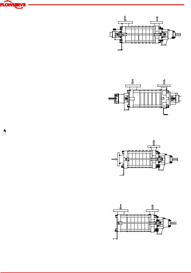
WDXR
Horizontal Radial suc tion
Drive end on discharge side - C W Thrust bearing on dri ve si de Radial bearing on suc tion side
2 shaft s eals
2.5 Recycling and end of product life
At the end of the service life of the product or its parts, the relevant materials and parts should be recycled or disposed of using an environmentally acceptable method and local regulations.
If the product contains substances which are harmful to the environment, these should be removed and disposed of in accordance with current regulations. This also includes the liquids and or gases in the "seal system" or other utilities.


 Make sure that hazardous substances or toxic fluid are disposed of safely and that the correct personal protective equipment is used. The safety specifications must be in accordance with the current regulations at all times.
3 PUMP DESCRIPTION
3.1 Configurations
The WDX type pump is a horizontal, multistage, radial split case, vaned diffuser type centrifugal pump equipped with a special suction impeller for low NPSH. It can be used with motor, steam turbine and gasoline or diesel engine drives.
The WDX pumps are of modular construction with identical stages being stacked axially to achieve the desired pressure output. Four high strength external tie rods connecting the two end casings hold them together. A variety of optimal features and materials allow it to fit a wide range of applications such as boiler feed or reverse osmosis.
Various orientations for the radial suction and discharge nozzles are allowed every 90° except towards the bottom.
The WDX can have the following configurations:
WDXC
Horizontal Radial suc tion
Drive end on suction side - CCW Thrust bearing on suc tion si de Radial bearing on disc harge side 2 shaft s eals
WDXE |
Horizontal End s uction
Drive end on discharge side - C W Thrust bearing on dri ve si de Sleeve bearing on sucti on si de
1 shaft s eal
WDXS
Horizontal Radial suc tion
Drive end on discharge side - C W Thrust bearing on dri ve si de Sleeve bearing on sucti on si de
1 shaft s eal
Page 12 of 46
WDX USER INSTRUCTIONS ENGLISH 71576322 06-05
®
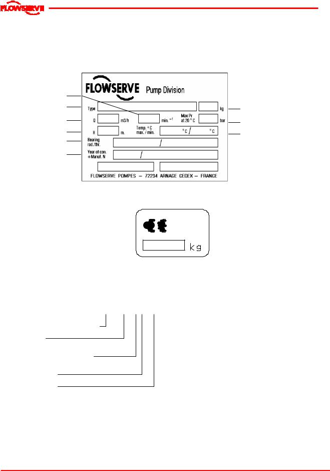
3.2 Nomenclature
Characteristics shown on the nameplate fixed on the pump are as shown below:
Each pump is supplied with the following nameplate:
Speed of rotation
Pump type
Flow rate
Head
Radial/thrust bearing
Year of c onstruc tion + Manufacture number
Mass
Maxi mum admissibl e Pressure at 20 °C
Maxi mum / mini mum temperature
Each pump unit is supplied with the following nameplate:
Mass of the set
The pump size will be engraved on the nameplate typically as below:
3.3 Design of major parts
4 WDX E 6 D
Nominal discharge branch size.
Series name
Configuration (see 3.1 above)
Number of stages
Hydraulic type
The typical nomenclature above is the general guide to the WDX configuration description. Identify the actual pump size and serial number from the pump nameplate. Check that this agrees with the applicable certification provided.
3.3.1 Pump casing
The pump casings (suction, discharge and stage) are sealedwitho’ringsanddesignedtocontainthe pressure s generated by the pump at the various possible design pressure s and temperatures.
3.3.2 Impeller
The impeller is fully shrouded and may be fitted with optional wear rings.
The suction impeller is specifically designed to have a low NPSH requirement.
3.3.3 Diffuser
The diffusers are fully machined to optimise performance.
3.3.4 Shaft
The shaft mounted on bearings with a keyed drive end.
Page 13 of 46

WDX USER INSTRUCTIONS ENGLISH 71576322 06-05
®
3.3.5 Pump bearings and lubrication
WDX pumps are designed so the antifriction bearings may be either oil or grease lubricated.
WDXE and WDXS have product lubricated line bearings with sleeve and bushing made of silicon carbide.
Bearing isolators or stationary labyrinths may be fitted as an option in the bearing covers to protect the bearings.
3.3.6 Bearing housing
Grease nipples enable grease lubricated bearings to be replenished between major service intervals. For oil-lubricated bearings, a constant level oiler is fitted.
3.3.7 Stuffing box housing
The stuffing box housing has a spigot (rabbet) fit between the pump casing and bearing housing for optimum concentricity. The design enables a number of sealing options to be fitted.
3.3.8 Shaft seal
The mechanical seal(s) attached to the pump shaft seals the pumped liquid from the environment. Stuffing boxes have been designed for component or cartridge seals. Gland packing may be fitted as an option.
3.3.9 Driver
The driver is normally an electric motor. Different drive configurations may be fitted such as internal combustion engines, turbines, hydraulic motors etc driving via couplings, belts, gearboxes, drive shafts etc.
3.3.10 Accessories
Accessories may be fitted when specified by the customer.
3.4 Materials of construction
Material |
Casing |
Impeller |
Shaft |
|
column |
||||
|
|
|
||
M2 |
Cast iron |
Cast iron |
Chrome steel |
|
|
|
|
|
|
M3 |
Carbon s teel |
Cast iron |
Chrome steel |
|
|
|
|
|
|
M4 |
Carbon s teel |
Stainless |
Chrome steel |
|
steel |
||||
|
|
|
||
M5 |
Chrome steel |
Stainless |
Chrome steel |
|
steel |
||||
|
|
|
||
M6 |
Duplex |
Stainless |
Duplex |
|
stainless s teel |
steel |
stainless s teel |
||
|
||||
M7 |
Stainless steel |
Stainless |
Duplex |
|
steel |
stainless s teel |
|||
|
|
3.5 Performance and operating limits
This product has been selected to meet the specifications of your purchase order. See the nameplate and section 1.5.
 The maximum allowable speed for cast iron impellers is 3600 RPM and for steel impellers is 4000 RPM.
3.5.1 Minimal flow
20 % of BEP up to 280° F (140 °C)
25 % of BEP between 280 °F (140 °C) and 410 °F (210 °C)
3.5.2 Clearance data
|
|
Nominal wear |
Nominal |
Nominal |
||||
|
|
Interstage |
Balance drum |
|||||
Size |
Mat |
ring clearance |
||||||
clearance |
clearance |
|||||||
min/max |
||||||||
|
|
min/max |
min/max |
|||||
|
|
mm (inch) |
||||||
|
|
mm (inch) |
mm (inch) |
|||||
|
|
|
|
|||||
1.5 |
M2 |
0.170/ |
0.259 |
0.170/ |
0.259 |
0.150/0.226 |
||
M3 |
(0.0067/ |
0.0102) |
(0.0067/ |
0.0102) |
(0.0059/0.0089) |
|||
|
||||||||
|
|
|
|
|
|
|
|
|
1.5 |
M4 to |
0.320/ |
0.409 |
0.170/ |
0.259 |
0.300/ |
0.376 |
|
M7 |
(0.0126/ |
0.0161) |
(0.0067/ |
0.0102) |
(0.0118/ |
0.0148) |
||
|
||||||||
|
|
|
|
|
|
|
|
|
2 |
M2 |
0.170/ |
0.259 |
0.170/ |
0.259 |
0.170/ |
0.259 |
|
M3 |
(0.0067/ |
0.0102) |
(0.0067/ |
0.0102) |
(0.0067/ |
0.0102) |
||
|
||||||||
|
|
|
|
|
|
|
|
|
2 |
M4 to |
0.330/ |
0.419 |
0.170/ |
0.259 |
0.470/ |
0.559 |
|
M7 |
(0.0130/ |
0.0165) |
(0.0067/ |
0.0102) |
(0.0185/ |
0.0220) |
||
|
||||||||
|
|
|
|
|
|
|
|
|
3 |
M2 |
0.200/ |
0.303 |
0.200/ |
0.303 |
0.170/ |
0.259 |
|
M3 |
(0.0079/ |
0.0119) |
(0.0079/ |
0.0119) |
(0.0067/ |
0.0102) |
||
|
||||||||
|
|
|
|
|
|
|
|
|
3 |
M4 to |
0.360/ |
0.463 |
0.200/ |
0.303 |
0.480/ |
0.569 |
|
M7 |
(0.0142/ |
0.0182) |
(0.0079/ |
0.0119) |
(0.0189/ |
0.0224) |
||
|
||||||||
|
|
|
|
|
|
|
|
|
4 |
M2 |
0.200/ |
0.303 |
0.200/ |
0.303 |
0.180/ |
0.269 |
|
M3 |
(0.0079/ |
0.0119) |
(0.0079/ |
0.0119) |
(0.0071/ |
0.0106) |
||
|
||||||||
|
|
|
|
|
|
|
|
|
4 |
M4 to |
0.410/ |
0.513 |
0.200/ |
0.303 |
0.500/ |
0.603 |
|
M7 |
(0.0161/ |
0.0202) |
(0.0079/ |
0.0119) |
(0.0197/ |
0.0237) |
||
|
||||||||
|
|
|
|
|
|
|
|
|
3.5.3 Sleeve bearing clearance (WDXE/S)
|
Diametral cl earance |
|
Pump size |
min/max |
|
|
mm (inch) |
|
1.5 WDX |
0.007 - 0.041 |
|
(0.0003 - 0.0016) |
||
|
||
|
|
|
2 WDX |
0.007 - 0.041 |
|
(0.0003 - 0.0016) |
||
|
||
|
|
|
3 WDX |
0.007 - 0.041 |
|
(0.0003 - 0.0016) |
||
|
||
|
|
|
4 WDX |
0.007 - 0.041 |
|
(0.0003 - 0.0016) |
||
|
||
|
|
3.5.4 Bearing bushings
Interstage bearing bushings can be mounted on the pump. Their number and location depend on the material chosen and the number of stages of the pump. For further information, see general arrangement drawing of the pump.
Page 14 of 46
 Loading...