


USER INSTRUCTIONS
Worthington® WXB centrifugal pumps
Horizontal, Multistage,Barrel
Original Instructions
PCN=71569257 07-14 (E)
Installation
Operation
Maintenance

CONTENTS |
|
|
PAGE |
1.0 INTRODUCTION AND SAFETY ......................... |
3 |
1.1 GENERAL ................................................................. |
3 |
1.2 CE MARKING AND APPROVALS ................................ |
3 |
1.3 DISCLAIMER ............................................................. |
3 |
1.4 COPYRIGHT ............................................................. |
3 |
1.5 DUTY CONDITIONS ................................................... |
3 |
1.6 SAFETY .................................................................... |
4 |
1.7 WARNING LABEL ...................................................... |
8 |
1.8 SPECIFIC MACHINE PERFORMANCE......................... |
9 |
1.9 NOISE LEVEL............................................................ |
9 |
1.10 CE DECLARATION ............................................... |
11 |
2.0 TRANSPORT AND STORAGE......................... |
12 |
2.1 CONSIGNMENT RECEIPT AND UNPACKING............. |
12 |
2.2 HANDLING .............................................................. |
12 |
2.3 LIFTING .................................................................. |
12 |
2.4 STORAGE ............................................................... |
13 |
2.5 RECYCLING AND END OF PRODUCT LIFE ............... |
13 |
3.0 DESCRIPTION .................................................. |
13 |
3.1 CONFIGURATION.................................................... |
13 |
3.2 NOMENCLATURE.................................................... |
13 |
3.3 DESIGN OF MAJOR PARTS ..................................... |
13 |
3.4 PERFORMANCE AND OPERATING LIMITS ............... |
14 |
4.0 INSTALLATION ................................................ |
14 |
4.1 LOCATION .............................................................. |
14 |
4.2 PART ASSEMBLIES ................................................ |
14 |
4.3 FOUNDATION ......................................................... |
14 |
4.4 INITIAL ALIGNMENT................................................. |
14 |
4.5 PIPING.................................................................... |
15 |
4.6 ELECTRICAL CONNECTIONS................................... |
17 |
4.7 FINAL SHAFT ALIGNMENT CHECK........................... |
17 |
5.0 COMMISSIONING START-UP, OPERATION |
|
AND SHUTDOWN................................................... |
17 |
5.1 PRECOMMISSIONING PROCEDURE ........................ |
17 |
5.2 PUMP LUBRICANTS................................................ |
18 |
5.3 IMPELLER CLEARANCE........................................... |
26 |
5.4 DIRECTION OF ROTATION ...................................... |
26 |
5.5 GUARDING ............................................................. |
26 |
5.6 PRIMING AND AUXILIARY SUPPLIES ....................... |
26 |
5.7 STARTING THE PUMP ............................................. |
26 |
5.8 OPERATION............................................................ |
26 |
5.9 STOPPING AND SHUTDOWN .................................. |
26 |
5.10 HYDRAULIC, MECHANICAL AND ELECTRICAL DUTY |
|
..................................................................................... |
27 |
6.0 MAINTENANCE ................................................ |
27 |
6.1 GENERAL ............................................................... |
27 |
6.2 MAINTENANCE SCHEDULE ..................................... |
28 |
6.3 SPARE PARTS ........................................................ |
28 |
6.4 RECOMMENDED SPARES ....................................... |
29 |
6.5 FASTENER TORQUES ............................................. |
30 |
6.6 SETTING IMPELLER CLEARANCE............................ |
31 |
6.7 DISASSEMBLY ........................................................ |
31 |
6.8 EXAMINATION OF PARTS........................................ |
32 |
WXB USER INSTRUCTIONS ENGLISH - 07/14
6.9 ASSEMBLY ............................................................. |
33 |
7.0 API DESIGN………………………………...…….35 |
|
7.1 MAINTENANCE SCHEDULE..................................... |
35 |
7.2 SPARE PARTS ........................................................ |
36 |
7.3 RECOMMENDED SPARES....................................... |
37 |
7.4 FASTENER TORQUES............................................. |
37 |
7.5 SETTING IMPELLER CLEARANCE............................ |
39 |
7.6 DISASSEMBLY........................................................ |
39 |
7.7 EXAMINATION OF PARTS........................................ |
40 |
7.8 ASSEMBLY ............................................................. |
41 |
8.0 AUXILIARIES.................................................... |
43 |
8.1 SEAL AND SEAL SYSTEMS ..................................... |
43 |
8.2 CHANGING OF MECHANICAL SEAL ......................... |
45 |
9.0 FAULTS; CAUSES AND REMEDIES .............. |
46 |
10.0 CERTIFICATION............................................. |
48 |
11.0 OTHER RELEVANT DOCUMENTATION AND |
|
MANUALS............................................................... |
48 |
11.1 SUPPLEMENTARY USER INSTRUCTIONS.............. |
48 |
11.2 CHANGE NOTES................................................... |
48 |
11.3 ADDITIONAL SOURCES OF INFORMATION ............ |
48 |
11.4 ABBREVIATIONS .................................................. |
49 |
Page 2 of 51

1.0INTRODUCTION AND SAFETY
1.1General
 These Instructions must always be kept close to product's operating location or directly with the product.
Flowserve's products are designed, developed and manufactured with state-of-the-art technologies in modern facilities. The unit is produced with great care and commitment to continuous quality control, utilising sophisticated quality techniques, and safety requirements.
Flowserve is committed to continuous quality improvement and being at service for any further information about the product in its installation and operation or about its support products, repair and diagnostic services.
These instructions are intended to facilitate familiarization with the product and its permitted use. Operating the product in compliance with these instructions is important to help ensure reliability in service and avoid risks. The instructions may not take into account local regulations; ensure such regulations are observed by all, including those installing the product. Always coordinate repair activity with operations personnel, and follow all plant safety requirements and applicable safety and health laws/regulations.
 These instructions must be read prior to installing, operating, using and maintaining the equipment in any region worldwide. The equipment must not be put into service until all the conditions relating to safety, noted in the instructions, have been met. Failure to follow and apply the present user instructions is considered to be misuse. Personal injury, product damage, delay or failure caused by misuse are not covered by the Flowserve warranty.
1.2 CE marking and approvals
It is a legal requirement that machinery and equipment put into service within certain regions of the world shall conform with the applicable CE Marking Directives covering Machinery and, where applicable, Low Voltage Equipment, Electromagnetic Compatibility (EMC), Pressure Equipment Directive (PED) and Equipment for Potentially Explosive Atmospheres (ATEX).
Where applicable the Directives, and any additional Approvals, cover important safety aspects relating to machinery and equipment and the satisfactory provision of technical documents and safety instructions. Where applicable this document incorporates information relevant to these Directives.
WXB USER INSTRUCTIONS ENGLISH - 07/14
To establish Approvals and if the product itself is CE Marked check the serial number plate and the Certification.
1.3 Disclaimer
Information in these User Instructions is believed to be reliable. In spite of all the efforts of Flowserve Corporation to provide sound and all necessary information the content of this manual may appear insufficient and is not guaranteed by Flowserve as to its completeness or accuracy.
Flowserve manufactures products to exacting International Quality Management System Standards as certified and audited by external Quality Assurance organisations. Genuine parts and accessories have been designed, tested and incorporated into the products to help ensure their continued product quality and performance in use. As Flowserve cannot test parts and accessories sourced from other vendors the incorrect incorporation of such parts and accessories may adversely affect the performance and safety features of the products. The failure to properly select, install or use authorised Flowserve parts and accessories is considered to be misuse. Damage or failure caused by misuse is not covered by Flowserve's warranty. In addition, any modification of Flowserve products or removal of original components may impair the safety of these products in their use.
1.4 Copyright
All rights reserved. No part of these instructions may be reproduced, stored in a retrieval system or transmitted in any form or by any means without prior permission of Flowserve.
1.5 Duty conditions
This product has been selected to meet the specifications of your purchaser order. The acknowledgement of these conditions has been sent separately to the Purchaser. A copy should be kept with these instructions.
 The product must not be operated beyond the parameters specified for the application. If there is any doubt as to the suitability of the product for the application intended, contact Flowserve for advice, quoting the serial number.
If the conditions of service on your purchase order are going to be changed (for example liquid pumped, temperature or duty) it is requested that the user seeks Flowserve´s written agreement before start up.
Page 3 of 51

1.6 Safety
1.6.1 Summary of safety markings
These user instructions contain specific safety markings where non-observance of an instruction would cause hazards. The specific safety markings are:
This symbol indicates electrical safety instructions where non-compliance will involve a high risk to personal safety or the loss of life.
 This symbol indicates safety instructions where non-compliance would affect personal safety and could result in loss of life.
 This symbol indicates "hazardous and toxic fluid" safety instructions where non-compliance would affect personal safety and could result in loss of life.
 This symbol indicates safety instructions where non-compliance will involve some risk to safe operation and personal safety and would damage the equipment or property.

 This symbol indicates "strong magnetic field" safety instructions where non-compliance would affect personal safety, pacemakers, instruments or stored data sensitive to magnetic fields.
 This symbol indicates explosive atmosphere marking according to ATEX. It is used in safety instructions where non-compliance in the hazardous area would cause the risk of an explosion.
 This symbol is used in safety instructions to remind not to rub non-metallic surfaces with a dry cloth; ensure the cloth is damp. It is used in safety instructions where non-compliance in the hazardous area would cause the risk of an explosion.
 The sign is not a safety symbol but indicates an important instruction in the assembly process.
 This symbol indicates potential risks connected with extremely high temperatures.
 This symbol indicates potential risks connected with extremely low temperatures.
WXB USER INSTRUCTIONS ENGLISH - 07/14
1.6.2 Personnel qualification and training
All personnel involved in the operation, installation, inspection and maintenance of the unit must be qualified to carry out the work involved. If the personnel in question do not already possess the necessary knowledge and skill, appropriate training and instruction must be provided. If required the operator may commission the manufacturer / supplier to provide applicable training.
Always co-ordinate repair activity with operations and health and safety personnel, and follow all plant safety requirements and applicable safety and health laws/regulations.
1.6.3 Safety action
This is a summary of conditions and actions to help prevent injury to personnel and damage to the environment and to equipment. For products used in potentially explosive atmospheres section 1.6.4 also applies.
 PREVENT EXCESSIVE EXTERNAL PIPE LOAD
Do not use pump as a support for piping. Do not mount expansion joints so that their force, due to internal pressure, acts on the pump flange.
 ONLY CHECK DIRECTION OF MOTOR ROTATION WITH COUPLING ELEMENT/ PINS REMOVED
Starting in reverse direction of rotation will damage the pump.
 ENSURE CORRECT LUBRICATION
(See section 5 Commissioning, startup, operation and shutdown.)
 START THE PUMP WITH OUTLET VALVE PART OPENED
(Unless otherwise instructed at a specific point in the user instructions.)
This is recommended to avoid the risk of overloading and damaging the pump motor at full or zero flow. Pumps may be started with the valve further open only on installations where this situation cannot occur. Pump outlet valve shall be adjusted to comply with the duty following the run-up process (See section 5 Commissioning, startup, operation and shutdown).
 START THE PUMP WITH OUTLET VALVE FULLY OPEN
This is recommended to avoid the risk of overloading and damaging the pump motor where greater power is taken at low or shut off flow. Pump outlet valve shall be adjusted to comply with the duty following the
Page 4 of 51

run-up process (See section 5 Commissioning, startup, operation and shutdown).
 NEVER RUN THE PUMP DRY
 BALANCE LINE MUST BE OPEN AT ANY TIME. (Except maintenance work)
 INLET VALVES TO BE FULLY OPEN WHEN PUMP IS RUNNING
Running the pump at zero flow or below the recommended minimum flow continuously will cause damage to the seal.
 DO NOT RUN THE PUMP AT ABNORMALLY HIGH OR LOW FLOW RATES Operating at a flow rate higher than normal or at a flow rate with no back pressure on the pump may overload the motor and cause cavitation. Low flow rates may cause a reduction in pump/bearing life, overheating of the pump, instability and cavitation/vibration.
 When ambient temperatures are likely to drop below freezing point, the pump and any cooling and flushing arrangements must be drained or otherwise protected.
 HANDLING COMPONENTS
Many precision parts have sharp corners and the wearing of appropriate safety gloves and equipment is required when handling these components. To lift heavy pieces above 25 kg (55 lbs) use a crane corresponding to the mass and in accordance with current local regulations.
NEVER DO MAINTENANCE WORK WHILST THE UNIT IS CONNECTED TO POWER
HAZARDOUS LIQUIDS
When the pump is handling hazardous liquids care must be taken to avoid exposure to the liquid by appropriate sitting of the pump, limiting personnel access and by operator training. If the liquid is flammable and/or explosive strict safety procedures must be applied.
Gland Packing must not be used when pumping hazardous liquids.
 DRAIN PUMP AND ISOLATE PIPEWORK BEFORE DISMANTLING THE PUMP
The appropriate safety precautions should be taken where the pumped liquids are hazardous.
 FLUORO-ELASTOMERS (When fitted)
WXB USER INSTRUCTIONS ENGLISH - 07/14
When a pump has experienced temperatures over 250 °C (482 ºF), partial decomposition of fluoroelastomers (example: Viton) will occur. In this condition these are extremely dangerous and skin contact must be avoided.
 GUARDS MUST NOT BE REMOVED WHILE PUMP IS OPERATIONAL
 THERMAL SHOCK
Rapid changes in the temperature of the liquid within the pump can cause thermal shock, which can result in damage or breakage of components and should be avoided.
 NEVER APPLY HEAT TO REMOVE IMPELLER
Trapped lubricant or vapour could cause an explosion.

 HOT AND COLD PARTS
If hot or freezing components or auxiliary heating supplies can present a danger to operators, they must be shielded to avoid accidental contact. If complete protection is not possible, the machine access must be limited to maintenance staff only. Note: bearing housings must not be insulated and drive motors and bearings may be hot.
If the temperature is greater than 68 °C (155 °F) o r below 5 °C (41 °F) in a restricted zone, or exceeds local regulations, action as above shall be taken.
1.6.4 Products used in potentially explosive atmospheres
 Measures are required to:
∙Avoid excess temperature
∙Prevent build up of explosive mixtures
∙Prevent the generation of sparks
∙Prevent leakages
∙Maintain the pump to avoid hazard
The following instructions for pumps and pump units when installed in potentially explosive atmospheres must be followed to help ensure explosion protection. Both electrical and non-electrical equipment must meet the requirements of European Directive 94/9/EC.
1.6.4.1 Scope of compliance
 Use equipment only in the zone for which it is appropriate. Always check that the driver, drive coupling assembly, seal and pump equipment are suitably rated and/or certified for the classification of the specific atmosphere in which they are to be installed.
Page 5 of 51

Where Flowserve has supplied only the bare shaft pump, the Ex rating applies only to the pump. The party responsible for assembling the pump set shall select the coupling, driver and any additional equipment, with the necessary CE Certificate/ Declaration of Conformity establishing it is suitable for the area in which it is to be installed.
The output from a variable frequency drive (VFD) can cause additional heating affects in the motor and so, for pump sets with a VFD, the ATEX Certification for the motor must state that it covers the situation where electrical supply is from the VFD. This is particular requirement still applies even if the VFD is in a safe area.
1.6.4.2 Marking
An example of ATEX equipment marking is shown below. The actual classification of the pump will be engraved on the nameplate.
II 2 GD c IIC135ºC (T4)
Equipment Group
I = Mining
II = Non-mining
Category
2 or M2 = High level protection
3 = normal level of protection
Gas and/or Dust
G = Gas; D= Dust
c = Constructional safety
(in accordance with EN13463-5)
b = Control of ignition source
(in accordance with EN13463-6) Gas Group
IIA – Propane (Typical)
IIB – Ethylene (Typical)
IIC – Hydrogen (Typical)
Maximum surface temperature (Temperature Class) (see section 1.6.4.3)
1.6.4.3 Avoiding excessive surface temperatures
 ENSURE THE EQUIPMENT TEMPERATURE CLASS IS SUITABLE FOR THE HAZARD ZONE
Pumps have a temperature class as stated in the ATEX Ex rating on the nameplate. These are based on an ambient in the range of -80 to +55 ºC (-112 to +131 ºF); refer to Flowserve for ambient temperatures outside this range for this product.
WXB USER INSTRUCTIONS ENGLISH - 07/14
The surface temperature on the pump is influenced by the temperature of the liquid handled. The maximum permissible liquid temperature depends on the ATEX temperature class and must not exceed the values in the table that follows.
|
Maximum |
Temperature limit of liquid |
|
Temperatur |
handled (* depending on |
||
surface |
|||
e class to |
material and construction |
||
temperature |
|||
EN 13463-1 |
variant - check which is |
||
permitted |
|||
|
lower) |
||
|
|
||
T6 |
85 °C (185 °F) |
Consult Flowserve |
|
T5 |
100 °C(212 °F) |
Consult Flowserve |
|
T4 |
135 °C (275 °F) |
115 °C (239 °F) * |
|
T3 |
200 °C (392 °F) |
180 °C (356 °F) * |
|
T2 |
300 °C (572 °F) |
275 °C (527 °F) * |
|
T1 |
450 °C (842 °F) |
400 °C (752 °F) * |
* The table only takes the ATEX temperature class into consideration. Pump design or material, as well as component design or material, may further limit the maximum working temperature of the liquid.
The temperature rise at the seals and bearings and due to the minimum permitted flow rate is taken into account in the temperatures stated.
The responsibility for compliance with the specified maximum liquid temperature is with the plant operator.
Temperature classification “Tx” is used when the liquid temperature varies and when the pump is required to be used in differently classified potentially explosive atmospheres. In this case the user is responsible for ensuring that the pump surface temperature does not exceed that permitted in its actual installed location.
Do not attempt to check the direction of rotation with the coupling element/pins fitted due to the risk of severe contact between rotating and stationary components.
Where there is any risk of the pump being run against a closed valve generating high liquid and casing external surface temperatures it is recommended that users fit an external surface temperature protection device.
Avoid mechanical, hydraulic or electrical overload by using motor overload trips or a Power Monitor and make routine vibration monitoring.
In dirty or dusty environments, regular checks must be made and dirt removed from areas around close clearances, bearing housings and motors.
1.6.4.4 Preventing the build up of explosive mixtures
 ENSURE THE PUMP IS PROPERLY FILLED AND VENTED AND DOES NOT RUN DRY
Page 6 of 51

Ensure the pump and relevant suction and discharge pipeline system is totally filled with liquid at all times during the pump operation, so that an explosive atmosphere is prevented. In addition it is essential to make sure that seal chambers, auxiliary shaft seal systems and any heating and cooling systems are properly filled.
If the operation of the system cannot avoid this condition the fitting of an appropriate Dry Run protection device is recommended (eg liquid detection or a Power Monitor).
To avoid potential hazards from fugitive emissions of vapour or gas to atmosphere the surrounding area must be well ventilated.
1.6.4.5 Preventing sparks
 To prevent a potential hazard from mechanical contact the coupling guard must be non-sparking and anti-static.
To avoid the potential hazard from random induced current generating a spark the earth contact on the baseplate must be used.
 Avoid electrostatic charge: do not rub nonmetallic surfaces with a dry cloth; ensure cloth is damp.
The coupling must be selected to comply with 94/9/EC and correct alignment must be maintained.
1.6.4.6 Preventing leakage
 The pump must only be used to handle liquids for which it has been approved to have the correct corrosion resistance.
Avoid entrapment of liquid in the pump and associated piping due to closing of suction and discharge valves, which could cause dangerous excessive pressures to occur if there is heat input to the liquid. This can occur if the pump is stationary or running.
Bursting of liquid containing parts due to freezing must be avoided by draining or protecting the pump and ancillary systems.
Where there is the potential hazard of a loss of a seal barrier fluid or external flush, the fluid must be monitored.
If leakage of liquid to atmosphere can result in a hazard, the installation of a liquid detection device is recommended.
WXB USER INSTRUCTIONS ENGLISH - 07/14
1.6.4.7 Maintenance to the centrifugal pump to avoid the hazard
 CORRECT MAINTENANCE IS REQUIRED TO AVOID POTENTIAL HAZARDS WHICH GIVE A RISK OF EXPLOSION
The responsibility for compliance with maintenance instructions is with the plant operator.
To avoid potential explosion hazards during maintenance, the tools, cleaning and painting materials used must not give rise to sparking or adversely affect the ambient conditions. Where there is a risk from such tools or materials, maintenance must be conducted in a safe area.
It is recommended that a maintenance plan and schedule is adopted (see section 6, Maintenance).to include the following.
a)Any auxiliary systems installed must be monitored, if necessary, to ensure they function correctly.
b)Gland packings must be adjusted correctly to give visible leakage and concentric alignment of the gland follower to prevent excessive temperature of the packing or follower.
c)Check for any leaks from gaskets and seals. The correct functioning of the shaft seal must be checked regularly
d)Check bearing lubricant level, and if the hours run show a lubricant change is required.
e)Check that the duty condition is in the safe operating range for the pump.
f)Check vibration, noise level and surface temperature at the bearings to confirm satisfactory operation.
g)Check dirt and dust is removed from areas around close clearances, bearing housings and motors.
h)Check coupling alignment and re-align if necessary.
Page 7 of 51
WXB USER INSTRUCTIONS ENGLISH - 07/14
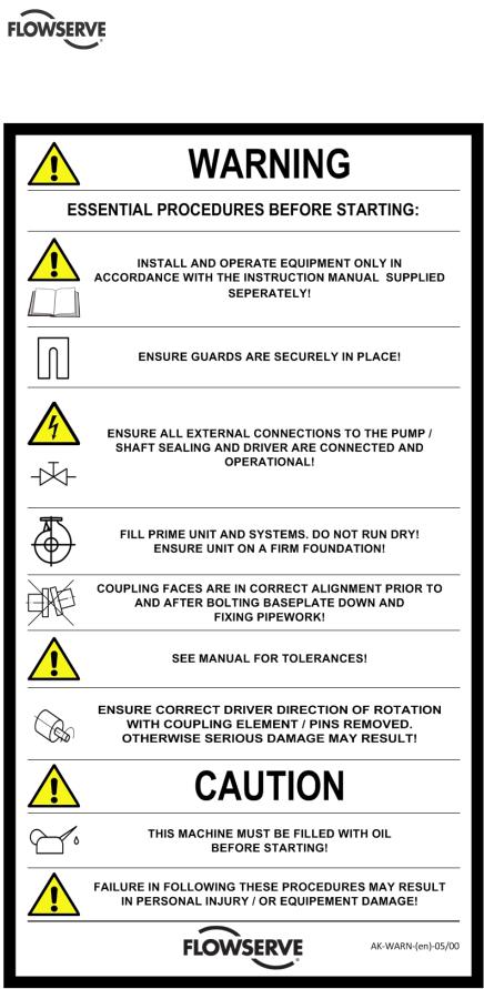
1.7 Warning label
Page 8 of 51

WXB USER INSTRUCTIONS ENGLISH - 07/14
1.8 Specific machine performance
For performance parameters see section 1.5, Duty conditions. When the Contract requirement specifies these to be incorporated into user instructions these are included here. Where performance data has been supplied separately to the purchaser these should be obtained and retained with these user instructions if required.
1.9 Noise level
Attention must be given to the exposure of personnel to the noise, and local legislation will define when guidance to personnel on noise limitation is required, and when noise exposure reduction is mandatory. This is typically 80 to 85 dBA.
The usual approach is to control the exposure time to the noise or to enclose the machine to reduce emitted sound. You may have already specified a limiting noise level when the equipment was ordered, however if no noise requirements were defined, then attention is drawn to the following table to give an indication of equipment noise level so that you can take the appropriate action in your plant.
Pump noise level is dependent on a number of operational factors, flow rate, pipework design and acoustic characteristics of the building, and so the values given are subject to a 3 dBA tolerance and cannot be guaranteed.
Similarly the motor noise assumed in the “pump and motor” noise is that typically expected from standard and high efficiency motors when on load directly driving the pump. Note that a motor driven by an inverter may show an increased noise at some speeds.
If a pump unit only has been purchased for fitting with your own driver then the “pump only” noise levels in the table should be combined with the level for the driver obtained from the supplier. Consult Flowserve or a noise specialist if assistance is required in combining the values.
It is recommended that where exposure approaches the prescribed limit, then site noise measurements should be made.
The values are in sound pressure level LpA at 1 m (3.3 ft) from the machine, for “free field conditions over a reflecting plane”.
For estimating sound power level LWA (re 1 pW) then add 14 dBA to the sound pressure value.
Page 9 of 51
WXB USER INSTRUCTIONS ENGLISH - 07/14
|
|
|
|
|
|
Octave MID BAND frequency [Hz] |
|
|
||||||||
|
Power B [HP] |
|
Power [kW] |
dB(A) Value |
63 |
|
250 |
500 |
|
1 K |
|
2 K |
|
4 K |
|
8 K |
|
|
125 |
|
|
|
|
||||||||||
|
|
|
|
|
|
|
|
|
|
|
|
|
|
|
|
|
|
53.7 |
|
40 |
77 |
67 |
71 |
71 |
69 |
|
69 |
|
69 |
|
67 |
|
62 |
|
70 |
|
52 |
78 |
68 |
72 |
72 |
70 |
|
70 |
|
70 |
|
68 |
|
63 |
|
91.2 |
|
68 |
79 |
69 |
73 |
73 |
71 |
|
71 |
|
71 |
|
69 |
|
64 |
|
119.4 |
|
89 |
80 |
70 |
74 |
74 |
72 |
|
72 |
|
72 |
|
70 |
|
65 |
|
157 |
|
117 |
81 |
71 |
75 |
75 |
73 |
|
73 |
|
73 |
|
71 |
|
66 |
|
206.7 |
|
154 |
82 |
72 |
76 |
76 |
74 |
|
74 |
|
74 |
|
72 |
|
67 |
|
269.7 |
|
201 |
83 |
73 |
77 |
77 |
75 |
|
75 |
|
75 |
|
73 |
|
68 |
|
354.3 |
|
264 |
84 |
74 |
78 |
78 |
76 |
|
76 |
|
76 |
|
74 |
|
69 |
|
464.3 |
|
346 |
85 |
75 |
79 |
79 |
77 |
|
77 |
|
77 |
|
75 |
|
70 |
|
609.3 |
|
454 |
86 |
76 |
80 |
80 |
78 |
|
78 |
|
78 |
|
76 |
|
71 |
|
798.5 |
|
595 |
87 |
77 |
81 |
81 |
79 |
|
79 |
|
79 |
|
77 |
|
72 |
|
1046.8 |
|
780 |
88 |
78 |
82 |
82 |
80 |
|
80 |
|
80 |
|
78 |
|
73 |
|
1372.9 |
|
1023 |
89 |
79 |
83 |
83 |
81 |
|
81 |
|
81 |
|
79 |
|
74 |
Sound pressure readings are for information only and are not subject to guarantee by Flowserve/IDP. Decibel readings do not include driver or system noise.
Pump tested at 100% of the best efficiency point at max.impeller diameter with water.
dB correction for combining noises (pump+motor)
Difference between two |
0 |
1 |
2 |
4 |
6 |
9 |
10 |
|
levels to be combined, dB |
||||||||
|
|
|
|
|
|
|
||
Add to the higher level to obtain |
3 |
2.5 |
2 |
1.5 |
1 |
0.5 |
0 |
|
the combined noise level,dB |
||||||||
|
|
|
|
|
|
|
Note :
1)The values showed are measured at a distance of 1 mt. (horizontally) from major pump surfaces and 1.5 mt. above the floor.
2)The values shown are expressed in dB (A)
3)For Noise Test Procedure refer to Works Standard L-109
4)The values shown have been derived from actual noise-test data and are based on the following conditions:
-Equipment is located in a free field above a reflecting plane in which the reductionin noise level in all directions is 6db in each octave band for each doubling of distance.
-Background noise is 10dB minimum below all noise levels in each octave band.
-The values shown are at a distance of 1 meter (horizontally) from the major pump surface and
1,5 meters above the floor, using a standard pressure reference of 0,00002 newton per square meter
-Overall noise level, dB(A) is determined at points of maximum noise level and the values of all mid-band frequences are basis A scale readings.
5)Above values are given for 2950 RPM.
When the required condition flow is outside the range of 75 to 125% BEP, a part load correction (PLC) must be added to the noise level as follows:
Percent of BEP @ required |
PLC |
impeller diameter |
in dB |
74 to 62 or 126 to 136 |
+1 |
61 to 50 or 137 to 150 |
+2 |
49 to 38 |
+3 |
37 to 25 |
+4 |
Page 10 of 51

WXB USER INSTRUCTIONS ENGLISH - 07/14
1.10 CE Declaration
Page 11 of 51
WXB USER INSTRUCTIONS ENGLISH - 07/14
2.0TRANSPORT AND STORAGE
2.1Consignment receipt and unpacking
Immediately after receipt of the equipment it must be checked against the delivery/ shipping documents for its completeness and that there has been no damage in transportation. Any shortage and or damage must be reported immediately to Flowserve and received in writing within one month of receipt of the equipment.
Latter claims cannot be accepted.
Check any create/boxes/wrappings for any Bare pumps shall be lifted as shown below. accessories or spare parts which may be packed
separately with the equipment or attached to side walls of the box or equipment.
Each product has a unique serial number. Check that this number corresponds with that advised and always quote this number in correspondence as well as when ordering spare parts or further accessories.
2.2 Handling
Boxes, crates, pallets or cartons may be unloaded using fork lift vehicles or slings dependent on their size and construction.
2.3 Lifting
Four lifting lugs are provided on the baseplate to lift the complete unit.
 Take care by applying slings or ropes about auxiliary piping and seal systems.
Page 12 of 51

 A crane must be used for all pump sets in excess of 25kg (55lb). Fully trained personnel must carry out lifting, in accordance with local regulations. The driver and pump weights are recorded on their respective nameplates.
2.4 Storage
If the unit will not be put immediately into service, it should be stored in a dry room. To avoid any damage during the storage period, the influence of any low or high frequency vibration must be totally inhibited. If the pump is delivered sealed in a plastic-wrapper, it is of max. importance to avoid any damage of that wrapper, because this will protect the pump against humidity. Therefore it must be checked if this wrapper has become cracked and if so, the wrapper must be renewed.
2.4.1 Long period storage
If the pump is delivered in a plastic bag, the preservations stands up for one year. If the storage period exceeds this time, the preservation must be checked and renewed. Also the air tight plastic bag must be changed. Moreover we recommend to order a Flowserve Service Engineer for checking the pump before the first start up.
2.5 Recycling and end of product life
At the end of the service life of the product or its parts, the relevant materials and parts should be recycled or disposed of using an environmentally acceptable method and local regulations. If the product contains substances which are harmful to the environment, these should be removed and disposed of in accordance with current regulations. This also includes the liquids and or gases in the "seal system" or other utilities.
 Make sure that hazardous substances are disposed of safety and that the correct personal protective equipment is used. The safety specifications must be in accordance with the current regulations at all times.
3.0DESCRIPTION
3.1Configuration
The model WXB belongs to Flowserves family of barrel pumps.
The pump line is based on a modular system, thus providing maximum design and operating flexibility. The maximum allowable working pressure range is from 100 bar for the smaller sizes up to 150 bar for the larger sizes. The pump is equipped with a balancing device for axial thrust compensation,
WXB USER INSTRUCTIONS ENGLISH - 07/14
usually used for heavy boiler feed service and hydrocarbon service.
It can be combined with an inducer for low NPSHA applications.
 The sense of rotation of the pump is clockwise (CW), looking from the coupling to the shaft end of the pump.
3.2 Nomenclature
Example:
3 WXB-10A8 – Ind.
3 Discharge nozzle in inch.
B Barrel
10 max. impeller size in inch
A type of hydraulics
8 no. of stages
Ind Inducer
3.3 Design of major parts
3.3.1 Bearing housing
Made of carbon steel. It is flanged to the pump casing and provides enough space for mechanical seals according to API 682.
3.3.2 Discharge and Suction head
Both heads are designed for the maximum allowable working pressure. To avoid any distorsion due to thermal expansion, centerline mounting is obligatory.
3.3.3 Balance device
To compensate the axial thrust a balancing device, consisting of a straight drum and a steped drum head is used. The step in the drum head separates the flow at the drum from the influence of the last stage impeller. This results in a smooth pressure distribution across the drum surface, which increases the rotordynamic stability and axial thrust compensation.
3.3.4 Hydraulics
The hydraulics consists of three parts:
∙Impeller with wear rings
∙Multivaned diffuser with return vanes, for radial load compensation
∙Channel ring, as internal pressure boundary and cross over to next stage
Page 13 of 51
3.3.5 Inducer
All different impellers can be optionally equipped with an inducer for low NPSHA applications.
3.3.6 Barrel
The barrel acts as pressure casing. The design allows that the pump internals can be pulled out fully assembled as complete hydraulic cartridge.
3.4 Performance and operating limits
 In the interest of operator safety the unit must not be operated above the nameplate conditions. Such operation could result in unit failure causing injury to operating personnel. Consult instruction book for correct operation and maintenance of the pump and its supporting components.
4.0 INSTALLATION
 Equipment operated in hazardous locations must comply with the relevant explosion protection regulations, see section 1.6.4, Products used in potentially explosive atmospheres.
4.1 Location
The pump should be located to allow room for access, ventilation, maintenance and inspection with ample headroom for lifting and should be as close as practicable to the supply of liquid to be pumped.
Refer to the general arrangement drawing for the pump set.
4.2 Part Assemblies
The pumps are delivered completely mounted and prealigned with the motor. Also the shaft seal is in the correct position. Final alignment after complete installation is necessary. If drivers and/or seal systems are delivered separately, follow the assembly procedure in section 6.8.
4.3 Foundation
The foundation shall be located on a place that allows a minimum of pipe work and that is easily accessible for inspection during operation. According to the environment the foundation may consist of concrete or of steel. It must be rigid and heavy enough to absorb normal vibrations and shocks.
4.3.1 Horizontal alignment of the baseplate
Horizontal alignment is done with levelling screws. Use a spirit level for correct horizontal alignment of the baseplate.
WXB USER INSTRUCTIONS ENGLISH - 07/14
 The max. misalignment is 0.5 mm/m baseplate length.
4.3.2 Steel foundation
When the pump unit is mounted directly on structural steel frame, it shall be well supported by constructural beams. It is recommended to check the natural frequency of the steel frame, because it shall not coincide with the pump speed. The exact horizontal alignment is very important!
 Ensure that the base plate is leveled horizontally to 0.5 mm/m. To avoid any distortion of put shims under the base plate before bolting it down to the steel frame. Welding of the base plate to the steel frame is not recommended because of possible distortion of the same.
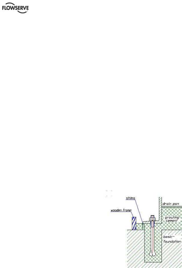
4.3.3 Concrete foundation
A concrete foundation must have an exact horizontal alignment and must be placed on solid ground. First a basic foundation shall be built with square shaped holes for embedding the foundation bolts. After putting the base plate into the foundation the proper alignment can be obtained by adjusting it with shims under the base plate. Now insert the foundation bolts and grout the space between the basic foundation and the base plate with grouting cement (refer to illustration)
It is very helpful to use a properly made and stable wooden frame around the base plate. So the grouting cement will not flow side. When the grouting is totally set and hardened the foundation bolts shall be tightened in a firm and symmetrical way.
4.4 Initial alignment
The adjustment of motor and pump must be checked (if necessary, make a new adjustment) before first start up of the unit.
Page 14 of 51
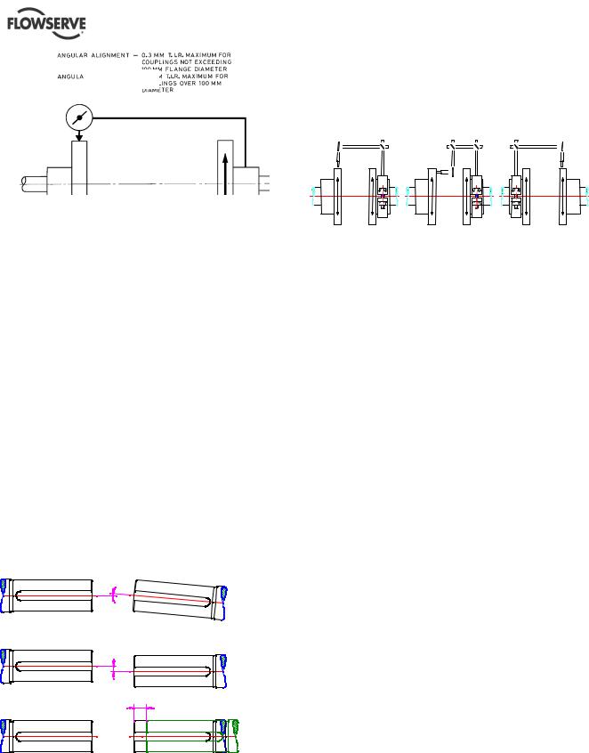
Parallel
Angular
Ensure pump and driver are isolated electrically and the half couplings are disconnected.
Align the motor to the pump, not the pump to the motor. Alignment of the motor is achieved by using the adjustment screws.
4.4.1 Permissible misalignment limits at working temperature
When checking parallel alignment, the total indicator read-out (TIR) shown is twice the value of the actual shaft displacement.
 The pump is only pre-aligned! Carefully check or read just alignment before start of the unit.
Take out the spacer of the coupling and check the alignment of shafts end of pump and driver. The maximum allowable angular offset should not exceed 0,05 degree, this means the alignment of the shaft ends should be 0,1 mm (0.004 in.). The maximum parallel offset should not exceed 0,05 mm
(0.002 in) and the axially offset can be ± 1 mm (0.04 in.).
For more details refer to the manufacturer’s
instruction manual of coupling.
a)
b)
c)
a)Angular Offset:The median lines of shafts intersect half-way between the ends of the two shafts.
b)Parallel Offset: The median lines run parallel. The maximum allowable parallel offset depends on the size of coupling and is indicated in the instruction manual of manufacturer of coupling
WXB USER INSTRUCTIONS ENGLISH - 07/14
c)Axially Offset: Another offset is the displacement of one or both of the shafts. A typical example is thermal expansion.
How the alignment of the coupling should be done you can see on the sketches and explanations below!
a) |
b) |
c) |
a)Fix the dial gauge on the driven shaft and check the concentricity by turning of both hubs; correct it if necessary.
b)Fix the dial gauge on one of the hubs and check the uniformity of the distance by turning of both hubs.; correct it if necessary.
c)Fix the dial gauge on the driving shaft and check the concentricity by turning of both hubs; correct it if
necessary.
If the pump is handling hot liquid, the alignment must be rechecked in warm condition of the unit.
4.5 Piping
4.5.1 General
Protective covers are fitted to the pipe connections to prevent foreign particles entering during transportation and installation. Ensure that these covers are removed from the pump before connecting any pipes.
Maximum forces and moments allowed on the pump flanges vary with the pump size and type. To minimize these forces and moments which may cause misalignment, hot bearings, worn couplings, vibration and a possible failure of the pump, the following points shall be strictly followed:
a)Prevent excessive external pipe load.
b)Do not connect piping by applying external force (use of wrenches, crane,...). Piping shall be aligned without residual stress.
c)Do not mount expansion joints so that their force, due to internal pressure, acts on the pump flange.
Fitting an isolator and non-return valves can allow easier maintenance. Never throttle pump on suction side and never place a valve directly on the pump inlet nozzle.
A non-return valve shall be located in the discharge pipework to protect the pump from excessive back pressure and hence reverse rotation when the unit is stopped.
Piping and fittings shall be flushed before use. To avoid damages of the pump install a Y-strainer or a
Page 15 of 51
strainer of 40 mesh.
Piping for corrosive liquids shall be arranged to allow pump flushing before removal of a unit.
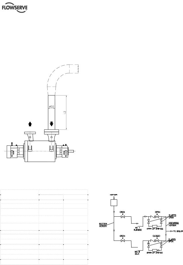
4.5.2 Inlet Piping Requirements *
Inlet flow disturbances, such as swirl, unbalance in the distribution of velocities and pressures, and sudden variations in velocity can be harmful to the hydraulic performance of a pump, its mechanical behavior, and its reliability.
Direction of
Fluid Flow
The minimum required straight pipe length (L2) before pump suction inlet is specified in Table 01. The straight pipe section is to be the same diameter as that of the pump section nozzle.
Table 01
Fitting*
90° elbow
Reducing elbow with <30% area reduction Reducing elbow with 30 to <50% area reduction Reducing elbow with >50% area reduction
Reducers
-) 1 pipe size reduction -) 2 pipe size reductions -) 3 pipe size reductions -) 4 pipe size reductions -) 5 pipe size reductions
Number of pipe diameters (ØD2)
Long radius ** |
Short radius ** |
4 |
5 |
3 |
4 |
2 |
3 |
0 |
1 |
Concentric |
Eccentric |
0 (<10°) |
0 (<20°) |
0 (<20°) |
1 (<30°) |
1 (<20°) |
2 (<30°) |
2 (<20°) |
3 (<40°) |
3 (<30°) |
4 (<40°) |
*excerpt from ANSI/HI 9.6.6-2009
**according to ASME B16.9-2003
WXB USER INSTRUCTIONS ENGLISH - 07/14
4.5.3 Vent
All WXB pump casings provide self venting through top discharge nozzle arrangement. A small bore at the top of the seal chamber ensures venting of the same.
4.5.4 Drain
This connection is used for total drainage of the pump casing. A flanged drain is standard and can be optionally equipped with various kinds of valves. Refer to GA drawing for details of the drain connection.
 By pumping toxic or explosive media, provide the necessary security actions, e.g. flushing with nitrogen.
4.5.5 Warm up requirements
A warm up arrangement is a means for maintaining an idle pump at approximate uniform temperature. We recommend a warm up procedure for liquid temperatures above 150°C (302°F).
Most commonly this arises when the pump is in boiler feed service. The pump which is started first will experience a gradual increase in water temperature after the boiler is fired and the unit warms up. However, when a second pump is to be put on the line, it is desirable to first bring it nearly to the prevailing feed water temperature by circulating water through it before it is started. Likewise, when a pump has been in operation and is taken off the line and shutdown, it is essential that water be circulated through it to maintain a uniform temperature. Otherwise it results in distortion of the close-running parts. If such a pump is started, rubbing would occur inside the pump.
A general arrangement of warm up piping is illustrated below.
Warm up flow:
2WXB: 2 m3/h (8,8 gpm) 3WXB: 3 m3/h (13,2 gpm) 4WXB: 4 m3/h (17,6 gpm) 6WXB: 5 m3/h (22 gpm)
Page 16 of 51
 Loading...