


Installation
Instructions
Durametallic® X-100
Single cartridge mounted welded metal bellows seal
Experience In Motion
Description
This X-100 seal is a cartridge mounted mechanical seal, designed for ease of installation and reliable operation. No seal setting dimensions are required. Removable setting devices provide proper alignment.
The flexible stationary face design compensates for inadvertent misalignment of the seal chamber face. Multiple springs provide uniform face loading and are external of the pumpage, resisting clogging or hang-up. Installation according to the following steps will assure long trouble free life of the X-100 seal.
1 Equipment Check
1.1Follow plant safety regulations prior to equipment disassembly:
•Lock out motor and valves.
•Wear designated personal safety equipment.
•Relieve any pressure in the system.
•Consult plant MSDS files for hazardous material regulations.
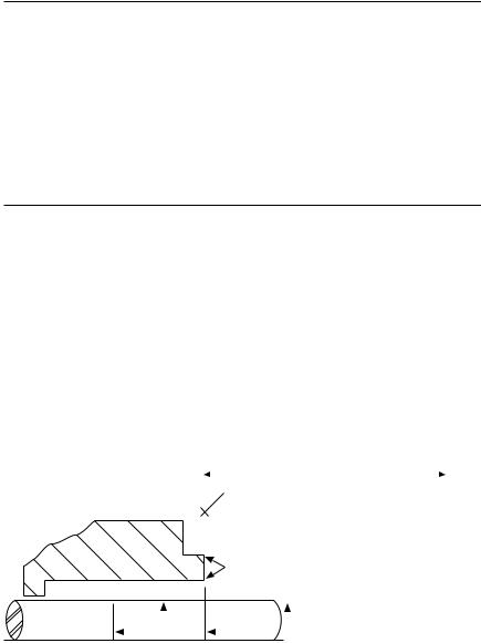
Seal Chamber Requirements |
Figure 1 |
|
|
|
|
|
|
|
|
|
|
|
|
|
|
|
To first obstruction |
|
|
|
||||
|
|
|
|
|
|
|
|
|
|
|
|
|
|
|
||||||
|
|
|
|
|
|
|
|
|
|
|
Face of seal housing to be square to the |
|
|
|||||||
|
|
|
|
|
|
|
|
|
|
|
axis of the shaft to within 0.0005 mm/mm |
|
|
|||||||
|
|
|
|
|
|
|
|
|
|
|
(0.0005 inch/inch) of seal chamber bore TIR |
|||||||||
|
|
|
|
|
|
|
|
|
|
|
and have a 1.6 |
μm (63 μinch) Ra finish or better |
||||||||
|
|
|
|
|
|
|
|
|
|
|
Gland pilot can be at either of these |
|
|
|||||||
|
|
|
|
|
|
|
|
|
|
|
register locations, concentric to within |
|
|
|||||||
|
|
|
|
|
|
|
|
|
|
|
0.125 mm (0.005 inch) of shaft or |
|
|
|||||||
|
|
Seal housing bore to have 3.2 μm |
|
|
|
sleeve OD TIR |
|
|
|
|
|
|
||||||||
|
|
(125 μinch) Ra finish or better |
|
|
|
|
|
|
|
|
|
|
|
|
|
|||||
|
|
Scribe |
|
|
Scribe |
|
|
Shaft or sleeve OD |
|
|
||||||||||
|
|
|
|
|
|
|
||||||||||||||
|
|
Mark |
B |
|
|
Mark |
A |
|
|
+0.000 mm (+0.000 inch) |
ANSI |
|||||||||
|
|
|
|
|||||||||||||||||
|
|
|
|
|
|
|
|
|
|
|
|
|
|
|
|
-0.050 mm (-0.002 inch) |
||||
|
Sleeve or shaft finish to be |
|
|
|
|
|
|
|
|
|
|
|
|
|
||||||
|
|
|
|
|
|
|
|
|
|
|
+0.000 mm (+0.000 inch) |
API 610/682 |
||||||||
|
|
|
|
|
|
|
|
|
|
|
||||||||||
|
0.8 μm (32 μinch) Ra or better |
|
|
|
|
|
|
|
-0.025 mm (-0.001 inch) |
DIN/ISO |
||||||||||
• Bearings must be in good condition |
|
|
|
|
|
|
|
|||||||||||||
|
|
|
|
|
|
|
|
|
|
|
|
|||||||||
• Maximum lateral or axial movement of shaft (end play) = 0.25 mm (0.010 inch) TIR |
|
|
||||||||||||||||||
• Maximum shaft runout at face of seal housing = 0.05 mm (0.002 inch) TIR |
|
|
||||||||||||||||||
• Maximum dynamic shaft deflection at seal housing = 0.05 mm (0.002 inch) TIR |
|
|
||||||||||||||||||
The images of parts shown in these instructions may differ visually from the actual parts due to manufacturing processes that do not affect the part function or quality.
2
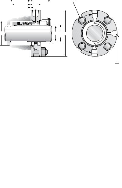
X-100 Dimensional Data |
Figure 2 |
|
|
|
|
|
|
|
|
|
C |
|
|
|
|
|
|
|
|
|
|
|
|
|
|
|
|
|
E |
|
|
|
|
|
|
|
|
|
|||||||||||||
|
|
|
|
|
|
|
|
|
|
|
|
|
|
|
|
F |
|
|
|
|
|
|
|
|
|
|
|
|
|||||||||||||||||||||
|
|
|
|
|
|
|
|
|
|
|
D |
|
|
|
|
|
|
|
|
|
|
|
|
|
|
|
|
|
|
|
|
|
|||||||||||||||||
|
|
|
|
|
|
|
|
|
|
|
|
|
|
|
|
|
|
|
|
|
|
||||||||||||||||||||||||||||
|
|
|
|
|
|
|
|
|
|
|
|
|
|
|
|
|
|
|
|
|
|
|
|
|
.03" |
|
|
|
|
|
|
|
|
|
|
|
|
|
|
|
|||||||||
|
|
|
|
|
|
|
|
|
|
|
|
|
|
|
|
|
|
|
|
|
|
|
|
|
|
|
|
|
|
|
|
|
|
|
|
|
|
|
|
|
|
|
|
|
|
|
|
|
|
|
|
|
|
|
|
|
|
|
|
|
|
|
|
|
|
|
|
|
|
|
|
|
|
|
|
|
|
|
|
|
|
|
|
|
|
|
|
|
|
|
|
|
|
|
|
|
|
|
|
|
|
|
|
|
|
|
|
|
|
|
|
|
|
|
|
|
|
|
|
|
|
|
|
|
|
|
|
|
|
|
|
|
|
|
|
|
|
|
|
|
|
|
|
|
|
|
|
|
|
|
|
|
|
|
|
|
|
|
|
|
|
|
|
|
|
|
|
|
|
|
|
|
|
|
|
|
|
|
|
|
|
|
|
|
|
|
|
|
|
|
|
|
|
|
|
|
|
|
|
B  Seal
Seal
A Size J
Dimensional Data for X-100 seal, inch
4 - G Ø studs equally spaced on HB. C. Note: Washers may be required for stud sizes smaller than G
Rotation |
Outlet |
|
|
CW |
|
CCW |
|
Rotation |
Outlet |
|
M (N.P.T.)
Seal Size |
A |
B |
B |
C |
D |
E |
F |
G |
H |
J |
M |
|
|
+0.000 |
|||||||||||
|
-0.002 |
±0.001 |
min. |
max. |
min. |
|
|
|
max. |
min. |
|
(N.P.T.) |
|
1.125 |
1.000 |
1.750 |
1.875 |
1.78 |
1.69 |
2.00 |
1.02 |
0.375 |
2.75 |
3.75 |
0.375 |
|
*1.250 |
1.125 |
1.750 |
2.000 |
1.78 |
1.69 |
2.00 |
1.02 |
0.500 |
3.00 |
3.88 |
0.375 |
|
1.375 |
1.250 |
2.000 |
2.125 |
1.97 |
1.88 |
2.00 |
1.02 |
0.500 |
3.12 |
4.25 |
0.375 |
|
*1.500 |
1.375 |
2.000 |
2.250 |
1.97 |
1.88 |
2.00 |
1.02 |
0.375 |
3.25 |
4.25 |
0.375 |
|
1.625 |
1.500 |
2.250 |
2.500 |
1.97 |
1.88 |
2.00 |
1.02 |
0.375 |
3.75 |
4.75 |
0.375 |
|
1.750 |
1.625 |
2.375 |
2.625 |
1.97 |
1.88 |
2.00 |
1.02 |
0.500 |
3.75 |
4.75 |
0.375 |
|
1.875 |
1.750 |
2.500 |
2.750 |
1.97 |
1.88 |
2.00 |
1.02 |
0.500 |
3.75 |
5.00 |
0.375 |
|
2.000 |
1.875 |
2.625 |
2.875 |
1.97 |
1.88 |
2.00 |
1.02 |
0.500 |
3.88 |
5.00 |
0.375 |
|
2.125 |
2.000 |
2.750 |
3.000 |
1.97 |
1.88 |
2.00 |
1.02 |
0.625 |
4 .12 |
5.12 |
0.375 |
|
2.250 |
2.125 |
2.875 |
3.250 |
1.97 |
1.88 |
2.00 |
1.02 |
0.625 |
4.38 |
6.00 |
0.375 |
|
2.375 |
2.250 |
3.000 |
3.375 |
1.97 |
1.88 |
2.00 |
1.02 |
0.625 |
4.62 |
6.50 |
0.375 |
|
2.500 |
2.375 |
3.250 |
3.625 |
2.16 |
2.06 |
2.09 |
1.11 |
0.625 |
5.00 |
6.38 |
0.375 |
|
2.625 |
2.500 |
3.375 |
3.750 |
2.16 |
2.06 |
2.09 |
1.11 |
0.625 |
5.00 |
6.62 |
0.375 |
|
2.750 |
2.625 |
3.500 |
3.875 |
2.16 |
2.06 |
2.09 |
1.11 |
0.750 |
5 .75 |
7.25 |
0.375 |
|
2.875 |
2.750 |
3.750 |
— |
2.16 |
2.06 |
2.62 |
1.58 |
|
|
|
0.750‡ |
|
†3.000 |
2.750 |
3.875 |
— |
2.16 |
2.06 |
2.62 |
1.58 |
|
|
|
0.750‡ |
|
3.000 |
2.875 |
3.875 |
— |
2.16 |
2.06 |
2.62 |
1.58 |
|
|
|
0.750‡ |
|
†3.125 |
2.875 |
4.000 |
— |
2.16 |
2.06 |
2.62 |
1.58 |
|
As |
|
0.750‡ |
|
3.125 |
3.000 |
4.000 |
— |
2.16 |
2.06 |
2.62 |
1.58 |
|
|
0.750‡ |
|
|
†3.250 |
3.000 |
4.125 |
— |
2.16 |
2.06 |
2.62 |
1.58 |
Required |
0.750‡ |
||
|
3.375 |
3.125 |
4.250 |
— |
2.16 |
2.06 |
2.62 |
1.58 |
0.750‡ |
|||
|
3.500 |
3.250 |
4.375 |
— |
2.28 |
2.19 |
2.75 |
1.71 |
|
|
|
0.750‡ |
|
3.625 |
3.375 |
4.500 |
— |
2.28 |
2.19 |
2.75 |
1.71 |
|
|
|
0.750‡ |
|
3.750 |
3.500 |
4.625 |
— |
2.28 |
2.19 |
2.75 |
1.71 |
|
|
|
0.750‡ |
|
3.875 |
3.625 |
4.750 |
— |
2.28 |
2.19 |
2.75 |
1.71 |
|
|
|
0.750‡ |
|
4.000 |
3.750 |
4.875 |
— |
2.28 |
2.19 |
2.75 |
1.71 |
|
|
|
0.750‡ |
|
4.125 |
3.875 |
5.000 |
— |
2.28 |
2.19 |
2.75 |
1.71 |
|
|
|
0.750‡ |
* |
this seal size uses the N-CBR inner seal rotary unit. |
|
|
|
|
|
|
|
||||
† |
preferred design for these shaft sizes. Use whenever possible. |
|
|
|
|
|
|
|||||
‡ maximum |
|
|
|
|
|
|
|
|
|
|
|
|
3
 Loading...