


|
USER INSTRUCTIONS |
Limitorque® WG Series |
Installation |
FCD LMENIM2101-02 – 1/15 |
Operation |
|
Maintenance |
|
|
Experience In Motion

Limitorque WG Series Worm Gear Operator FCD LMENIM2101-02 – 01/15
Contents
1 |
Introduction |
4 |
|
|
1.1 |
Purpose |
4 |
|
1.2 |
User Safety |
4 |
2 |
Inspection, Installation and Mounting Procedures |
5 |
|
|
2.1 |
Initial Inspection and Storage Instructions |
6 |
|
2.2 |
Inspection and Recording |
6 |
|
2.3 |
Storage Procedure |
6 |
|
2.4 |
General Mounting Instructions |
7 |
|
2.5 |
Assembly Positions |
8 |
|
2.6 |
Setting Position Limit Stops - WG-00 Through 12 |
9 |
3 |
Lubrication |
10 |
|
4 |
Disassembly and Reassembly Instructions |
11 |
|
|
4.1 |
Safety Precautions |
11 |
|
4.2 |
Safety Practices |
12 |
|
4.3 WG-00 Through WG-35 |
12 |
|
|
4.4 WG-04 Through WG-12 |
16 |
|
|
4.5 |
Single Reduction Spur Gear Attachment (1S) |
20 |
|
4.6 |
Double Reduction Spur Gear Attachment (1SD) |
22 |
5 |
How to Order Parts |
24 |
|
Figures
Figure 2.1 – Typical WG Exploded View |
5 |
||
Figure 2.2 – Assembly Position A |
8 |
||
Figure 2.3 – Assembly Position D |
8 |
||
Figure 2.4 – Setting Position Limit Stops |
9 |
||
Figure 4.1 – Splined Adapter Assembly |
12 |
||
Figure 4.2 – WG-00 Through WG-35 Exploded View |
13 |
||
Figure 4.3 – WG-00 Through WG-35 Assembly View |
14 |
||
Figure 4.4 – WG-00 Through WG-35 Assembly View |
14 |
||
Figure 4.5 – WG-00 Through WG-35 Assembly View |
15 |
||
Figure 4.6 |
– WG-00 Through WG-35 Assembly View |
15 |
|
Figure 4.7 |
– WG-04 Through WG-12 Splined Adapter Assembly |
16 |
|
Figure 4.8 |
– WG-04 Through WG-12 Exploded View |
17 |
|
Figure 4.9 |
– WG-04 Through WG-12 Assembly View |
18 |
|
Figure 4.10 – WG-04 Through WG-12 Assembly View |
18 |
||
Figure 4.11 |
– WG-04 Through WG-12 Assembly View |
19 |
|
Figure 4.12 |
– WG-04 Through WG-12 Assembly View |
19 |
|
Figure 4.13 |
– WG-00 Through WG-12 Spur Gear Attachment (1S) Exploded View |
21 |
|
Figure 4.14 |
– WG-00 Through WG-12 Spur Gear Attachment (1SD) Exploded View |
23 |
|
2

Limitorque WG Series Worm Gear Operator FCD LMENIM2101-02 – 1/15
Tables
Table 3.1 – Lubricants |
|
10 |
||
Table 4.1 |
– WG-00 |
Through WG-35 Parts List |
15 |
|
Table 4.2 |
– WG-04 |
Through WG-12 |
Parts List |
19 |
Table 4.3 |
– WG-00 |
Through WG-12 |
Spur Gear Attachment (1S) Parts List |
21 |
Table 4.4 |
– WG-00 |
Through WG-12 |
Spur Gear Attachment (1SD) Parts List |
23 |
3
flowserve.com

Limitorque WG Series Worm Gear Operator FCD LMENIM2101-02 – 01/15
1 Introduction
1.1 Purpose
The installation and maintenance manual (IOM) explains how to install and maintain the Flowserve Limitorque WG operator. Information on installation, disassembly, reassembly, lubrication and spare parts is provided.
1.2 User Safety
Safety notices in this manual detail precautions the user must take to reduce the risk of personal injury and damage to the equipment. The user must read and be familiar with these instructions before attempting installation, operation or maintenance. Failure to observe these precautions could result in serious bodily injury, damage to the equipment, voiding of the warranty, or operational difficulty.
Safety notice is presented in this manual in three forms:
cWARNING: Refers to personal safety. Alerts the user to potential danger. Failure to follow warning notices could result in personal injury or death.
aCAUTION: Directs the user’s attention to general precautions that, if not followed, could result in personal injury and/or equipment damage.
NOTE: Highlights information critical to the user’s understanding of the operator’s installation and operation.
4
Limitorque WG Series Worm Gear Operator FCD LMENIM2101-02 – 1/15
2 Inspection,
Installation and
Mounting Procedures
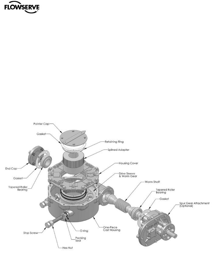
Figure 2.1 – Typical WG Exploded View
cWARNING: Do not manually operate the WG operator with devices other than the installed handwheel or wrench nut. Using additive force devices (cheater bars, wheel wrenches, pipe wrenches, or other devices of this nature) on the operator handwheel, wrench or wrench nut may cause serious personal injury and/or damage to the operator or valve.
5
flowserve.com

Limitorque WG Series Worm Gear Operator FCD LMENIM2101-02 – 01/15
2.1 Initial Inspection and Storage Instructions
c WARNING: Read this installation and maintenance manual carefully and completely before attempting to store the operator. If an electric actuator is attached to the WG manual operator, be aware of the electrical hazards. Consult the electric actuator installation and maintenance manual for guidance.
2.2 Inspection and Recording
Upon receipt of the operator, inspect the condition of the equipment, and record nameplate information.
1.Carefully remove operator from shipping carton or skid. Thoroughly examine the equipment for any physical damage that may have occurred during shipment. If damaged, immediately report the damage to the transport company.
2.A nameplate is attached to each operator with the following information:
•Operator size
•Assembly position
•Order number
•Serial number
•Customer tagging
Record this information for future reference, e.g., ordering parts, or obtaining further information.
2.3 Storage Procedure
NOTE: The following is the recommended storage procedure to retain maximum product integrity during storage. Failure to comply with recommended procedure will void the warranty.
Storage (less than one year)
Store operators on wooden skids to protect the machined mounting flange. Place the wooden skids containing the operators in a clean, dry, protected warehouse. If the operators must be stored outside, they must be covered in polyethylene protection with silica gel crystals to absorb moisture. If an electric actuator is attached to the WG, refer to the storage procedures in its respective manual for appropriate storage procedures. Rotate input shafts every three months to mix the lubricant.
6

Limitorque WG Series Worm Gear Operator FCD LMENIM2101-02 – 1/15
2.4General Mounting Instructions
aCAUTION: To avoid the potential for disengaging the worm gear segment, ensure that the pointer cap pointer is oriented to the mid-point of the 90º valve travel. Full stroke rotation of the quadrant should not move the pointer past the corresponding Open or Close ID marks on the housing cover.
The mounting instructions for the WG series worm gearboxes are outlined below. The WG-00 through WG-35 gearboxes are designed with a bottom entry splined adapter. The WG-04 through WG-12 gearboxes are designed with a top entry splined adapter. A separate set of instructions for each design is provided. See Section 2.4.1 for the WG-00 through WG-35 and Section 2.4.2 for the WG-04 through WG-12.
2.4.1 WG-00 through WG-35
1. Place the valve disk in the full closed position.
Note: If the Splined Adapter is already installed in the operator, go to step 6.
2.Remove the Pointer Cap (see Section 4 for removal instructions).
3.Turn the gearbox upside down so that the bottom of the housing is accessible.
4.Remove the Retaining Ring, and install the Splined Adapter.
Note: The notch in the Worm Gear at the Closed position must be aligned with the keyway in the Splined Adapter.
5.Reinstall the Retaining Ring.
6.Place the gearbox in the upright position so that the top of the gearbox is accessible.
7.Mount the operator on the valve and bolt securely.
8.Rotate the input shaft to align the keyway of the Splined Adapter with the keyway of the Valve Shaft and install the key.
9.Confirm that the gearbox Stop Screws are properly set for valve disk travel in both the Open and Close directions of travel. See Section 2.6.
10.Reinstall the Pointer Cap.
7
flowserve.com

Limitorque WG Series Worm Gear Operator FCD LMENIM2101-02 – 01/15
2.4.2 WG-04 through WG-12
1.Place the valve disk in the full closed position.
2.Remove the Pointer Cap (see Section 4 for removal instructions).
Note: If the Splined Adapter is already installed in the operator, go to step 6.
3. Remove the Retaining Ring and install the Splined Adapter.
Note: The notch in the Worm Gear at the Closed position must be aligned with the keyway in the Splined Adapter.
4.Reinstall the Retaining Ring.
5.Mount the operator on the valve and bolt securely.
6.Rotate the input shaft to align the keyway of the Splined Adapter with the keyway of the Valve Shaft and install the key.
7.Confirm that the gearbox Stop Screws are properly set for valve disk travel in both the Open and Close directions of travel. See Section 2.6.
8.Reinstall the Pointer Cap.
2.5Assembly Positions
Figure 2.2 – Position A
STANDARD ASSEMBLY POSITION
Clockwise Input Rotation –
Clockwise Output Rotation
Figure 2.3 – Position D
OPTIONAL ASSEMBLY POSITION
Clockwise Input Rotation –
Counterclockwise Output Rotation
8
 Loading...