


|
USER INSTRUCTIONS |
Edward Valves |
Installation |
Univalve |
Operation |
|
Maintenance |
|
|
Experience In Motion
FCD EVENIM2000-02(E)
(Bulletin V-370 R3)
1
EDWARD UNIVALVE USER INSTRUCTIONS ENGLISH 12-13
INTRODUCTION
EDWARD CUSTOMER SERVICE
Consult your Edward factory inside sales representative for information on obtaining repair tools.
As always, field sales and service personnel are available to assist with maintenance and repairs involving Edward
valves. And they are backed up by factory-trained specialists to lend additional assistance whenever needed.
An improved low-maintenance Univalve design... tools for fast in-line repairs...and reliable Edward service!
TABLE OF CONTENTS |
|
Edward Customer Service .............................................. |
2 |
Three Tools for Faster In-line Repairs |
|
of Edward Univalves........................................................ |
2 |
Exploded View................................................................. |
3 |
Disassembling the Univalve........................................ |
4–5 |
Servicing Edward Univalve Stop and Stop-check Valves...6 |
|
Servicing Edward Univalve Check Valves......................... |
7 |
Alternate Weld-cutting Methods for Univalves................. |
8 |
Univalve Maintenance Tools..................................... |
9–13 |
Reassembly of the Univalve.................................... |
14–17 |
Reassembly of Unwelded Bonnet Univalves.............. |
14 |
Reassembly of Welded Bonnet Univalves.................. |
14 |
Replacing the Seal Weld Univalves................................ |
18 |
A105 and F22 Univalves............................................ |
18 |
F316 and F347 Univalves.......................................... |
18 |
Operational Recommendations............................... |
19–20 |
General Information................................................ |
21–22 |
TABLES |
|
Valves With No Prefix in Figure Numbers............... |
10–11 |
Valves With “B” Prefix Figure Numbers......................... |
12 |
Valves With “C” and “D” Prefix Figure Numbers*.......... |
13 |
Unwelded Univalve Bonnet Gasket Torques................... |
15 |
Welded Univalve Bonnet Torques.................................. |
16 |
Torque Range for Packing Gland Bolts.......................... |
17 |
Minimum Torque for Closing Valves — |
|
ft-lb on Main Seat........................................................................ |
19 |
Impactor Handle/Handwheel Performance Chart........... |
20 |
THREE TOOLS FOR FASTER IN-LINE REPAIRS OF EDWARD UNIVALVES
Edward Univalves aren’t likely to require any maintenance or repair work until they’ve been in services for quite a few years. But sooner or later – depending on the nature of the fluids, frequency of operation and time in service – Univalve seats and disks may need to be repaired.
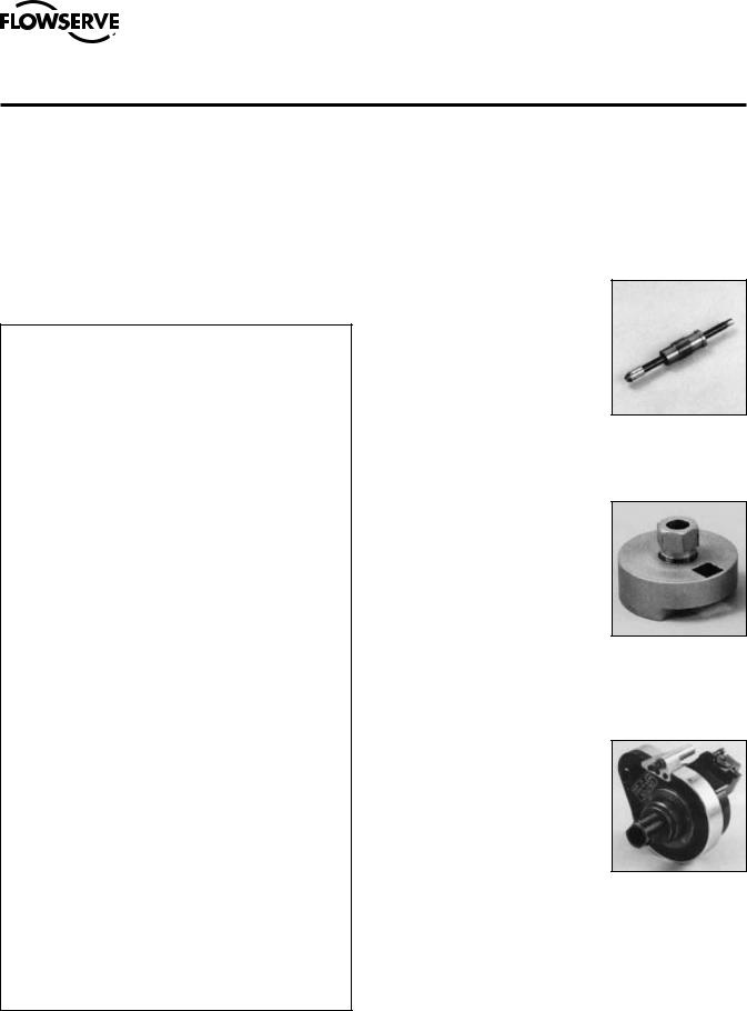
The Seat Refinishing Tool has a self-centering head of multiple tungsten carbide cutters on a spindle which is hand-operated
with a speed wrench for complete seat refinishing. Lapping or other finishing work is not required to produce refinished seats.
Seat damage, such as that produced by foreign materials in the line fluids, can be repaired quickly.
The Bonnet Torquing Collar is essentially a torque wrench adapter that is used to remove
and reassemble the bonnet of an unwelded Univalve.
The tool facilitates reassembly of the bonnet with the required
torque correctly applied to ensure that the graphitic body-bonnet gasket is properly loaded to establish a leak-tight seal. The tool may also be used to assemble and disassemble seal-welded valves.
The Seal Weld Cutting Machine has the ability to cut both fillet and canopy welds. By removing the handwheel and yoke, then installing the machine, seal welds can be cut, leaving a suitable weld prep. The machine is operated by one person and uses conventional plant air.
Seat Refinishing Tool
Bonnet Torquing Collar
Seal Weld Cutting Machine
2

EDWARD UNIVALVE USER INSTRUCTIONS ENGLISH 12-13
EXPLODED VIEW
1
2
3
16
15
14
13 |
|
|
|
|
|
|
|
|
|
|
|
|
|
|
|
4 |
|
|
|||
|
|
|
|
|
|
|
|
|
|
|
|
|
|
|
|
||||||
|
|
|
|
|
|
|
|
|
|
|
|
|
|
|
|
|
|
|
|
||
|
|
|
|
|
|
|
|
|
|
|
|
|
|
|
|
|
|
|
|
||
12 |
|
|
|
|
|
|
|
|
|
|
|
|
|
|
|
|
|
|
|
|
|
|
|
|
|
|
|
|
|
|
|
|
|
|
|
|
|
|
|
|
|
||
|
|
|
|
|
|
|
|
|
|
|
|
|
|
|
|
|
|
|
|
||
11 |
|
|
|
|
|
|
|
|
|
|
|
|
|
|
|
|
|
|
|
|
|
|
|
|
|
|
|
|
|
|
|
|
|
|
|
|
|
|
|
|
|
||
10 |
|
|
|
|
|
|
|
|
|
|
|
|
|
|
|
5 |
|
|
|||
|
|
|
|
|
|
|
|
|
|
|
|
|
|
|
|
|
|||||
|
|
|
|
|
|
|
|
|
|
|
|
|
|
(shown turned 90°) |
|
|
|||||
|
|
9 |
|
|
|
|
|
|
|
|
|
|
|
|
|
|
6 |
|
|
||
|
|
|
|
|
|
|
|
|
|
|
|
|
|
|
|
|
|
||||
|
|
8 |
|
|
|
|
|
|
|
|
|
|
|
|
|||||||
|
|
|
|
|
|
|
|
|
|
|
|
|
|||||||||
|
|
|
|
|
|
|
|
|
|
|
|
|
|
|
|
|
|
|
|||
|
|
|
|
|
|
|
|
|
|
|
|
|
|
|
|
|
|
|
|||
|
|
|
|
|
|
|
|
|
|
|
|
|
|
|
|
|
|
|
|
|
|
|
|
|
|
|
|
|
|
|
|
7 |
|
|
|
|
|
|
|
|
|
||
|
|
|
|
|
|
|
|||||||||||||||
1. |
Stem Nut |
6. |
|
Body |
11. |
Yoke Belt |
|||||||||||||||
2. |
Washer |
7. |
|
Yoke Nut |
12. |
Gland |
|||||||||||||||
3. |
Handwheel |
8. |
|
Graphitic Gasket* |
13. |
Yoke |
|||||||||||||||
4. |
Stem/Disk Assembly |
|
|
(unwelded bonnet valves only) |
14. |
Gland Adjusting Screws |
|||||||||||||||
9. |
|
Bonnet |
|||||||||||||||||||
5. |
Locking Collar |
|
15. |
Cap Plugs |
|||||||||||||||||
10. |
Packing |
||||||||||||||||||||
|
|
(unwelded bonnet valves only) |
16. |
Yoke Bushing |
|||||||||||||||||
|
|
|
|
|
|
|
|
|
|
|
|
|
|
|
|
|
|
|
|||
|
|
|
|
|
|
|
|
|
|
|
|
|
|
|
|
|
|
|
|
|
|
*Class 4500 welded bonnet Univalves have a bonnet insert and graphic gasket seal ring, as shown on page 14.
3

EDWARD UNIVALVE USER INSTRUCTIONS ENGLISH 12-13
DISASSEMBLING THE UNIVALVE
Line pressure must be relieved before disassembling the valve.
1.Double-check to make sure that line pressure has been relieved before disassembling the valve.
2.The valve should be in the open position and not against the body seat or backseat.
5.Loosen the yoke clamp bolt and nut. It is not necessary to completely remove them.
6.Remove the yoke assembly by unscrewing it from the bonnet. A gentle tap with a hammer might be necessary before the yoke will unscrew away from the bonnet. You may find it easier to remove the yoke by placing the handwheel on the stem to prevent the stem from rotating. When the yoke is even with the top of the stem, and you can no longer use the valve handwheel or handle, you will need to grasp the lower portion of the stem between the yoke and bonnet. If the yoke is turning freely, a cloth may be adequate to hold the stem. If this is not adequate, a strap wrench that will not damage the stem surface should be used. If only the packing is to be replaced, this can now
be easily done with no further disassembly of the Univalve. See Step 14.
3.If the valve is manually operated, remove the lock nut that attaches the handwheel or impactor handle to the valve stem. Remove the handwheel or handle. If the valve is motor operated, remove the actuator from the valve stem.
4.Loosen the two gland adjustment screws that rest against the packing gland by threading them higher into the yoke. A hex allen wrench inserted into the top of the gland screw thru the holes in the top of the yoke (remove the dirt protectors first) will speed this up.
7.If the yoke bushing is worn or damaged and must be removed, insert 1⁄8” (or smaller) abrasive grinding wheel into the slot on top of the bushing. Using a standard grinding tool, work the grinder downward
to remove yoke metal that was upset into the bushing during the valve assembly. Periodically during the grinding process, try to turn the bushing within the yoke to test how loose it is becoming. Once loosened, use a screwdriver in the slot to turn the bushing. To reinsert a new bushing, thread it into the yoke so that the top of the bushing is flush with the top of the yoke. Using a chisel and hammer, tap the yoke metal into the bushing slot, creating an offset, so that the bushing is tight within the yoke.
4
EDWARD UNIVALVE USER INSTRUCTIONS ENGLISH 12-13
DISASSEMBLING THE UNIVALVE (continued)
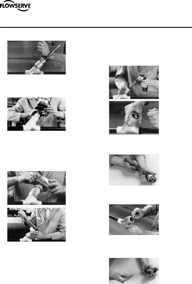
8.If the valve is unwelded, remove the locking collar.
11.Remove the valve bonnet-stem-disk assembly if the valve being repaired is a stop valve (figure XXX2X). The disk in a stop-check vaIve (figure XXX6X) and the bonnet insert in welded Class 4500 vaIves (figure 961XX) may be removed by forming a short piece of soft wire into the shape of an L and lifting it up in the disk bore.
9.If the valve to be repaired is seal-welded, prepare the Seal Weld Cutting Machine for the weld cutting
operation. If a cutting machine is not available, use one of the alternate methods shown on pg. 8.
10.Refer to the chart on pp. 10–13 to select the proper torquing collar assembly (consisting of lock nut and collar). Screw the torquing collar clockwise onto the bonnet until it bottoms. A left hand threaded lock nut is used to lock the torquing tool to the bonnet. Use the appropriate size open end or socket/box wrench (1-¼", 1-¾" or 2" hex) on the lock nut to turn the tool counterclockwise to remove the bonnet.
12.Remove the stem from the bonnet. It may be necessary to rotate the stem through the packing before it can be removed.
13.If the valve is unwelded, the graphitic gasket must be replaced. Do so by removing it from the valve body, but take care not to damage machined surfaces.
14.Using a packing tool, remove the old packing. Stainless steel Univalves are equipped with a metal junk ring in the bottom of the packing chamber. (See pg. 16 for repacking instructions.)
5
EDWARD UNIVALVE USER INSTRUCTIONS ENGLISH 12-13
SERVICING EDWARD UNIVALVE STOP AND STOP-CHECK VALVES
Line pressure must be relieved before making any repairs.
If seat damage has occurred, outlined below are step-by- step procedures for fast, in-line repairs using the Edward Seat Refinishing Tool.
1.See pp. 4–5 for proper disassembly procedures before performing repairs on the Univalves. Then, using the charts on pp. 10–13, select the proper Seat Refinishing Tool Arrangement for performing repairs on the seat area.
2.Take appropriate caution to make sure the inlet and outlet valve ports are blocked to prevent removed seat material from entering the line. Then, screw the Seat Refinishing Tool Assembly into the body while holding the shaft up to prevent tool and seat contact. The guide needs only to be hand-tightened. Do not damage the cutters by dropping the tool on the stellite seat.
3.The Seat Refinishing Tool is now ready for operation. Use a speed wrench to operate the tool. Because this manual process is fast, a special air or electric motor should not be used. The tool assembly can be easily removed to inspect the seat and determine if more seat refinishing is required. Turn the tool clockwise using light pressure only on the stellite seat.
Univalves can be reseated several times, assuming nominal amounts of stellite are removed each time. A typical resealing operation removes several
thousandths of an inch of stellite; severe seat defects, of course, would remove more. A total of about
.03 inch of stellite can be removed before the stellite becomes too thin, or approximately five average refinishing operations.
4.When a repair of the seat is finished, use a portable vacuum to remove loose chips.
6

EDWARD UNIVALVE USER INSTRUCTIONS ENGLISH 12-13
SERVICING EDWARD UNIVALVE CHECK VALVES
Line pressure must be relieved before servicing the valve.
1.If the check valve to be repaired is seal-welded, prepare the Seal Cutting Machine for the weld-cutting operation. If a cutting machine is not available, use one of the alternate methods on pg. 8.
3.Remove the check valve spring and disk from the body bore. A short piece of soft wire formed into an L shape may be used to assist in disk removal by engaging it in the groove inside the disk.
2.Once a seal-welded valve has been cut, it is ready for disassembly. Unscrew vaIve cover from the body using the flats provided.
4.The check valve is now ready for internal work. See the section entitled “Servicing Edward Univalve
Stop and Stop-Check Valves” (pg. 6) for correct repair procedures.
7
EDWARD UNIVALVE USER INSTRUCTIONS ENGLISH 12-13
ALTERNATE WELD-CUTTING METHODS FOR UNIVALVES
Line pressure must be relieved before making any repairs.
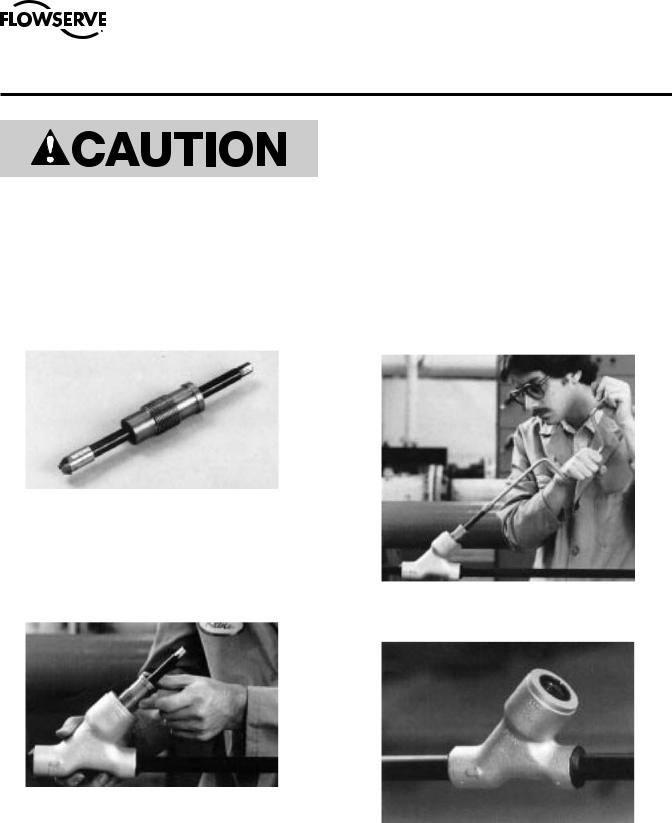
GRINDING A WELD
(For canopy seal Univalves) stainless steel valves
Open valve to backseat. Using a standard grinding wheel, remove the weld by grinding from the top of the body face and bonnet outside diameter (see photo). Continue this process around the valve until all weld is removed where the body and bonnet are joined together. Clean the valve with a wire brush. A penetrating oil may be used where permissible to loosen the threads joining the body and bonnet.
SCARFING A WELD
(For fillet-welded Univalves) carbon steel and low alloy valves
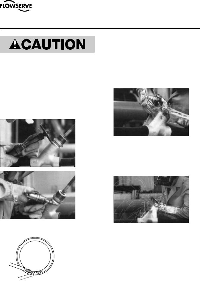
1.Air-arc method Open valve to backseat.
Using air-arc equipment, make a series of cuts in the valve weld (see photo and sketch). Continue making cuts until the valve weld takes on a grooved scarfedout appearance. Clean the valve with a wire brush.
A penetrating oil may be used where permissible to loosen the threads joining the body and bonnet.
2.Oxyacetylene method Open valve to backseat. Using an oxyacetylene torch equipped with a scarfing tip, make a series of cuts in the weld until it takes on a scarfed-out, grooved appearance. Clean the valve with a wire brush. A penetrating oil may be used where permissible to loosen threads joining the body and bonnet.
|
This sketch shows the sequence of cuts necessary to remove the fillet weld by both |
|
oxyacetylene and air-arc methods. Place scarfing torch or welding electrode tangent |
|
to the bonnet, as indicated in position A. When metal reaches cutting temperature, |
|
start blowing oxygen or air while moving torch backward. Weld metal should be |
|
blown away. Move torch counterclockwise to position B. Repeat until entire fillet |
|
weld is removed and gap is continuous. DO NOT REMOVE EXCESS MATERIAL |
A |
FROM BONNET OR UPPER BODY FACE. |
|
B |
|
|
8
 Loading...