


Valtek Position Pac
GENERAL INFORMATION
The following instructions are designed to assist with installing, calibrating and troubleshooting the Valtek® Position Pac™ valve position indicator. Product users and maintenance personnel should thoroughly review this bulletin in conjunction with the maintenance bulletin for the appropriate valve body and actuator being used.
To avoid possible injury to personnel or damage to valve parts, WARNING and CAUTION notes must be strictly adhered to. Modifying this product, substituting non-factory or inferior parts, or using maintenance procedures other than outlined could drastically affect performance, be hazardous to personnel and equipment, and may void existing warranties.
Position Pac’s sealed construction provides protection from the entry of water, dust and oil as defined by the National Electrical Manufacturers Association (NEMA) 1, 3, 3R, 4, 12 and 13. Position Pac is also explosionproof, providing protection from flammable hydrocarbon atmospheres, metal dust, coal dust, and grain dust. It is UL and CSA listed for Class I, Division 1, Groups B, C, D; Class II, Division 1, Groups E, F, G (See Table I). All electrical wiring should be installed per NEC articles 501-4 and 501-5.
WARNING: Keep hands, hair, clothing, etc. away from moving parts when operating the valve. Failure to do so can cause serious injury.
INSTALLATION INSTRUCTIONS
The following instructions are designed to assist in the field installation of Position Pac units.
OPERATION
Position Pac is a ‘package’ unit containing a potentiometer and transmitter, two or four limit switches, or a combination of a transmitter and two limit switches.
The position transmitter utilizes a potentiometer to measure the valve’s position and a transmitter circuit that sends a 4 to 20 mA electrical signal to a remote monitoring device. Position Pac will continuously transmit the position of a control valve as it modulates between the open and closed positions.
The limit switches in Position Pac can be independently set to indicate open, closed or any intermediate valve position.
Valtek Linear Actuators
To install Position Pac on Valtek linear actuators, refer to Figures 1 and 2, and proceed as follows:
1.Remove the name plate from the yoke leg opposite from the stroke indicator plate.
2.Using the two tapped holes, attach the Position Pac mounting bracket to the yoke leg using two mounting bolts. When facing this yoke leg, the bracket will jog in towards the valve center and protrude to the left.
3.Remove the nut from the stem clamp bolting. Place the tripper bracket on the bolt so the ‘S’ shape extends down. Replace the nut and tighten it firmly.
ValtekFlowserveNoCorporation,. 62152 Valtek Control Products,FlowserveT lCorporation,. USA 801 489Valtek8611Control Products, Tel. USA 801 489 8611 |
29-1 |
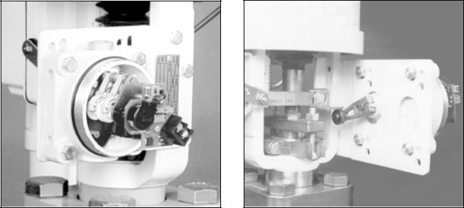
Figure 1: Linear Application – Front View |
Figure 2: Linear Application – Rear View |
|
||||||||||||||||
|
(cover removed) |
|
|
|
|
|
|
|
|
|
(cover removed) |
|
|
|
||||
|
|
|
|
|
|
|
|
|
|
|
|
|
|
|
|
|||
|
|
Table I: Model Configuration |
|
|
|
|
|
|
||||||||||
|
|
|
|
|
|
|
|
|
|
|
|
|
|
|
|
|
|
|
|
|
|
|
|
|
Electrical Area |
|
|
|
|
|
|
|
|
||||
|
|
|
|
|
|
|
|
|
|
|
|
|
|
|
|
|
|
|
|
|
|
|
|
|
Explosion Proof |
|
|
|
|
|
Sealed |
Housing |
|
||||
Model |
Description |
NEMA |
|
Class I Division |
|
Class II Division |
CENELEC |
Rating |
|
Switches |
Size |
|
||||||
|
|
4 |
|
1 & 2 (Group) |
|
1 & 2 |
(Group) |
Approval |
|
|
|
|||||||
|
|
|
|
|
|
|
|
|
||||||||||
|
|
|
A |
|
B |
C |
D |
|
E |
|
F |
G |
|
|
|
|
|
|
|
|
|
|
|
|
|
|
|
|
|
|
|
|
|
|
|
|
|
TH2 |
Analog Transmitter with two her- |
|
|
|
|
|
|
|
|
|
|
|
|
UL |
|
Yes |
Long |
|
metically sealed SPDT switches |
|
|
|
|
|
|
|
|
|
|
|
|
|
|
||||
|
|
|
|
|
|
|
|
|
|
|
|
|
|
|
|
|
|
|
H2TS |
Two hermetically sealed SPDT |
|
|
|
|
|
|
|
|
|
|
|
|
UL |
|
Yes |
Long |
|
switches with terminal switch |
|
|
|
|
|
|
|
|
|
|
|
|
|
|
||||
|
|
|
|
|
|
|
|
|
|
|
|
|
|
|
|
|
|
|
TX |
Analog transmitter |
|
|
|
|
|
|
|
|
|
|
|
|
UL/CSA |
|
No |
Short |
|
|
|
|
|
|
|
|
|
|
|
|
|
|
Pending |
|
|
|
|
|
TA2 |
Analog transmitter with two |
|
|
|
|
|
|
|
|
|
|
|
UL |
|
No |
Long |
|
|
|
|
|
|
|
|
|
|
|
|
|
|
|
|
|||||
SPDT switches |
|
|
|
|
|
|
|
|
|
|
|
|
|
|
||||
|
|
|
|
|
|
|
|
|
|
|
|
|
|
|
|
|
|
|
A2 |
Two SPDT switches |
|
|
|
|
|
|
|
|
|
|
|
|
UL |
|
No |
Short |
|
A4 |
Four SPDT switches |
|
|
|
|
|
|
|
|
|
|
|
|
UL |
|
No |
Long |
|
A2TS |
Two SPDT switches with |
|
|
|
|
|
|
|
|
|
|
|
|
UL |
|
No |
Long |
|
terminal strip |
|
|
|
|
|
|
|
|
|
|
|
|
|
|
||||
|
|
|
|
|
|
|
|
|
|
|
|
|
|
|
|
|
|
|
Table II: Linear Mounting Information
Actuator |
Valve |
Spud |
Kit |
Hole |
|
Size |
Stroke |
Size |
No.* |
Set |
|
(sq. in.) |
(inch) |
(inch) |
|
(Mounting) |
|
|
|
|
|
|
|
25 |
|
0.5-1.0 |
2.00 |
37434 |
bottom of slot |
|
|
1.5 |
2.00 |
37434 |
top of slot |
|
|
|
|
|
|
50 |
|
0.5-2.5 |
2.62 |
37345 |
bottom holes |
|
|
|
|
|
|
|
|
3.0 |
2.62 |
37345 |
top holes |
|
|
|
|
|
|
100 |
|
1.0-3.5 |
2.62/2.88 |
37436 |
bottom holes |
|
|
|
|
|
|
& larger |
4.0 |
3.38 |
37630 |
top holes |
|
|
|
|
|
|
|
|
|
4.0 |
4.75 |
71636 |
top holes |
*Kit includes: bracket, arm, trip lever or stem clamp with trip lever nuts and bolts.
4.Mount Position Pac to the bracket using the mounting holes as specified in Table II: Insert the lever onto the switch shaft. On larger actuators (size 50 and larger) that use the adjustable lever arm, adjust the length so that the center of the roller rests on the center of the tripper bracket. To preload the Position Pac’s restoring spring, be certain the control valve is in its minimum signal position. Loosen the lever arm clamp screw with a 0.14-inch ( 9/64) hex wrench, allowing the arm to turn on the shaft. While holding the arm in contact with the bottom of the tripper bracket and using a slotted screwdriver to rotate the switch shaft perform the following (all rotation direction instructions are as viewed from the lever arm side of the Position Pac):
29-2 |
Flowserve Corporation, Valtek Control Products, Tel. USA 801 489 8611 |

Figure 3: Rotary Application – Rear View |
Figure 4: Rotary Application – Front View |
(cover removed; air-to-close valve) |
(cover removed; air-to-close valve) |
|
|
For direct-acting, air-to-open actuators, rotate the shaft counter clockwise as far as it will go, then back off approximately 5 to 10 degrees. For direct-acting, air-to- close actuators, rotate the shaft counter clockwise approximately 5 to 10 degrees.
For reverse-acting, air-to-open actuators, rotate the shaft counter clockwise approximately 5 to 10 degrees. For reverse-acting, air-to-close actuators, rotate the shaft counter clockwise as far as possible, then back off approximately 5 to 10 degrees. With the slot in this position, tighten lever arm clamp screw tightly (until the teller tab will not move). With this procedure completed, stroke valve to ensure spring is preloaded throughout the entire valve travel.
5.To make electrical connections, remove the housing cover.
WARNING: On explosion-proof installations, disconnect electrical power or be certain the area is safe from combustible atmospheres before removing the housing cover.
(Refer to the specifications in Table IV for component electrical ratings.) Attach transmitter signal wiring to the transmitter terminal block, using caution to attach the positive and negative wires to the appropriate terminal.
CAUTION: Do not apply a voltage greater than 40 volts to the transmitter terminals or the circuit will be damaged.
Attach limit switch wiring to the ‘COMM’ (common) and either ‘NC’ (normally closed) or ‘NO’ (normally open) terminals according to the needed signal.
6.To adjust the limit switches and/or position transmitter, remove the housing cover and refer to the Calibration section in this document.
WARNING: On explosion-proof installations, disconnect electrical power or be certain the area is safe from combustible atmospheres before removing the housing cover.
7.Replace the housing cover.
8.Reinstall the name plate to the mounting bracket.
NOTE: Name plate reinstallation is important for valve identification/servicing purposes.
Valtek Rotary Actuators
To install Position Pac on Valtek rotary actuators, refer to Figures 3 and 4, and proceed as follows:
1.Mount the bracket to the mounting pad on the backside of the actuator using two 0.31-inch (5/16) mounting bolts.
2.Mount the Position Pac to the bracket using four 0.31-inch (5/16) mounting bolts and nuts.
3.Loosely mount the trip lever to the valve shaft within the yoke.
4.Attach the switch lever to the Position Pac shaft.
5.Connect the linkage assembly to both levers as shown in Figure 3.
6.Measure the approximate radius of the trip lever from the center of the valve shaft to the linkage assembly connection (not the end of the lever). Next, adjust the switch lever to approximately the same radius and tighten.
Flowserve Corporation, Valtek Control Products, Tel. USA 801 489 8611 |
29-3 |
 Loading...