


Vertical Turbine Pumps
Wet Pit (VTP)
Double Casing (VPC)
E, S and A series VTPs in wet pit and suction barrel designs ranging in sizes from 50 mm (6 in.) to 1300 mm (52 in.) with a single or multiple stages. (This manual does not cover VTPs fitted with thrust bearing assemblies and VTPs built for cryogenic service).
PCN=71569224 10-13(E), Based on VTP-QS-0896 Original Instructions
USER INSTRUCTIONS
Installation
Operation
Maintenance
 These instructions must be read prior to installing, operating, using and maintaining this equipment

VERTICAL TURBINE PUMPS (VTPS) CENTRIFUGAL PUMPS ENGLISH 71569224 – 10-13
CONTENTS |
PAGE |
|
|
PAGE |
|||
|
|
|
|
|
|||
1 INTRODUCTION AND SAFETY ....................... |
4 |
6 MAINTENANCE............................................... |
46 |
||||
1.1 |
General............................................................ |
4 |
6.1 |
General .......................................................... |
47 |
||
1.2 |
CE Marking and Approvals.............................. |
4 |
6.2 |
Maintenance Schedule .................................. |
47 |
||
1.3 |
Disclaimer........................................................ |
4 |
6.3 |
Spare Parts .................................................... |
49 |
||
1.4 |
Copyright ......................................................... |
4 |
6.4 |
Recommended Spares and Consumables.... |
49 |
||
1.5 |
Duty Conditions ............................................... |
4 |
6.5 |
Tools Required ............................................... |
49 |
||
1.6 |
Safety .............................................................. |
5 |
6.6 |
Fastener Torques ........................................... |
50 |
||
1.7 |
Safety Labels Summary .................................. |
8 |
6.7 |
Setting Impeller Clearance............................. |
51 |
||
1.8 |
Specific Machine Performance........................ |
8 |
6.8 |
Disassembly................................................... |
51 |
||
1.9 |
Noise Level...................................................... |
8 |
6.9 |
Examination of Parts...................................... |
51 |
||
1.10 |
Specific machine performance ................ |
9 |
6.10 |
Assembly................................................ |
55 |
||
2 |
TRANSPORT AND STORAGE....................... |
10 |
7 FAULTS; CAUSES AND REMEDIES ............. |
56 |
|||||
|
2.1 |
Consignment receipt and unpacking............. |
10 |
8 DRAWINGS AND PARTS LISTS |
58 |
||||
|
2.2 |
Handling |
10 |
||||||
|
8.1 Cross Section: Product Lubricated VTP |
58 |
|||||||
|
2.3 |
Lifting |
10 |
||||||
|
8.2 Cross Section: Enclosed Tube VTP |
61 |
|||||||
|
2.4 |
Storage |
14 |
||||||
|
8.3 Cross Section: Suction Barrel VTP |
64 |
|||||||
|
2.5 |
Recycling and End of Product Life |
14 |
||||||
|
8.4 General Arrangement Drawing |
67 |
|||||||
3 |
DESCRIPTION |
14 |
|||||||
9 |
CERTIFICATION |
67 |
|||||||
|
3.1 |
Configuration |
14 |
||||||
|
|
|
|
|
|||||
|
3.2 |
Nomenclature ................................................ |
16 |
10 OTHER RELEVANT DOCUMENTATION AND |
|||||
|
3.3 |
Design of Major Parts.................................... |
17 |
|
MANUALS........................................................ |
67 |
|||
|
3.4 |
Performance and Operation Limits................ |
21 |
10.1 |
Supplementary User Instructions........... |
67 |
|||
4 |
INSTALLATION |
21 |
10.2 |
Change Notes ........................................ |
67 |
||||
|
|
|
|
||||||
|
4.1 |
Location ......................................................... |
21 |
11 |
APPENDIX ....................................................... |
68 |
|||
|
4.2 |
Preparation.................................................... |
21 |
11.1 |
Bill of Materials Reference Numbers ..... |
68 |
|||
|
4.3 |
Foundation..................................................... |
21 |
|
|
|
|
||
|
4.4 |
Grouting......................................................... |
23 |
|
|
|
|
||
|
4.5 |
Lifting and Assembly ..................................... |
24 |
|
|
|
|
||
|
4.6 |
Initial Alignment ............................................. |
30 |
|
|
|
|
||
|
4.7 |
Piping............................................................. |
31 |
|
|
|
|
||
|
4.8 |
Electrical Connections................................... |
34 |
|
|
|
|
||
|
4.9 |
Final Shaft Alignment Check ......................... |
34 |
|
|
|
|
||
|
4.10 |
Protection Systems................................ |
34 |
|
|
|
|
||
5 |
COMMISSIONING, STARTUP, OPERATION |
|
|
|
|
|
|||
|
AND SHUTDOWN ........................................... |
35 |
|
|
|
|
|||
|
5.1 |
Pre-commissioning Procedure ...................... |
35 |
|
|
|
|
||
|
5.2 |
Pump Lubricants ........................................... |
35 |
|
|
|
|
||
|
5.3 |
Impeller Adjustment....................................... |
38 |
|
|
|
|
||
|
5.4 |
Direction of Rotation...................................... |
41 |
|
|
|
|
||
|
5.5 |
Guarding........................................................ |
41 |
|
|
|
|
||
|
5.6 |
Priming and Auxiliary Supplies...................... |
41 |
|
|
|
|
||
|
5.7 |
Starting the Pump.......................................... |
42 |
|
|
|
|
||
|
5.8 |
Operating the Pump ...................................... |
45 |
|
|
|
|
||
|
5.9 |
Stopping and Shutdown ................................ |
46 |
|
|
|
|
||
5.10Hydraulic, mechanical and electrical duty46
Page 2 of 76 |
flowserve.com |

VERTICAL TURBINE PUMPS (VTPS) CENTRIFUGAL PUMPS ENGLISH 71569224 – 10-13
INDEX
PAGE |
PAGE |
Alignment of shafting (see 4.3, 4.6 and 4.9) |
|
Assembly (6.10)....................................................... |
55 |
ATEX marking (1.6.4.2) ............................................. |
7 |
Bill of materials reference numbers (11.1) …….......68 |
|
CE marking and approvals (1.2)................................ |
4 |
Certification (9) ........................................................ |
67 |
Change notes (10.2)................................................ |
67 |
Clearances, impeller (6.7) ....................................... |
51 |
Commissioning and operation (5) ........................... |
35 |
Compliance, ATEX (1.6.4.1)...................................... |
6 |
Configurations (3.1) ................................................. |
14 |
Copyright (1.4)........................................................... |
4 |
Design of major parts (3.3) ...................................... |
17 |
Direction of rotation (5.4) ......................................... |
41 |
Disassembly (6.8).................................................... |
51 |
Disclaimer (1.3) ......................................................... |
4 |
Dismantling (6.8, Disassembly)............................... |
51 |
Drawings (8) ............................................................ |
58 |
Duty conditions (1.5).................................................. |
4 |
Electrical connections (4.8) ..................................... |
34 |
End of product life (2.5) ........................................... |
14 |
Examination of parts (6.9) ....................................... |
52 |
Fastener torques (6.6) ............................................. |
50 |
Faults; causes and remedies (7) ............................. |
56 |
Foundation (4.3) ...................................................... |
21 |
General arrangement drawing (8.4) ........................ |
67 |
General assembly drawings (8)............................... |
58 |
Grouting (4.4)........................................................... |
23 |
Guarding (5.5).......................................................... |
41 |
Handling (2.2) .......................................................... |
10 |
Hydraulic, mechanical and electrical duty (5.10)..... |
46 |
Impeller clearance (6.7)........................................... |
51 |
Inspection (6.2.1 and 6.2.2)..................................... |
48 |
Installation (4) .......................................................... |
21 |
Lifting (2.3)............................................................... |
10 |
Location (4.1)........................................................... |
21 |
Lubrication (5.2)....................................................... |
35 |
Maintenance (6)....................................................... |
47 |
Maintenance schedule (6.2) .................................... |
47 |
Name nomenclature (3.2)........................................ |
16 |
Nameplate (1.7.1)...................................................... |
8 |
Nozzle loads (4.7.2)................................................. |
31 |
Operating limits (3.4.1) ............................................ |
21 |
Ordering spare parts (6.3.1) .................................... |
49 |
Parts lists (8)............................................................ |
58 |
Performance (3.4).................................................... |
21 |
Piping (4.7) .............................................................. |
31 |
Pre-commissioning (5.1).......................................... |
35 |
Priming and auxiliary supplies (5.6) ........................ |
41 |
Protection systems (4.10)........................................ |
34 |
Reassembly (6.10, Assembly)................................. |
55 |
Receipt and unpacking (2.1).................................... |
10 |
Recommended spares (6.4).................................. |
499 |
Recycling (2.5) ......................................................... |
14 |
Replacement parts (6.3 and 6.4) ............................. |
49 |
Running the pump (5.8) ........................................... |
45 |
Safety action (1.6.3)................................................... |
5 |
Safety labels (1.7.2) ................................................... |
8 |
Safety markings (1.6.1).............................................. |
5 |
Safety, protection systems (see 1.6 and 4.10) |
|
Sealing arrangements (3.3.7) .................................. |
19 |
Sectional drawings (8).............................................. |
58 |
Setting impeller clearance (6.7) ............................... |
51 |
Sound pressure level (1.9, Noise level) ..................... |
8 |
Spare parts (6.3) ...................................................... |
49 |
Specific machine performance (1.8) .......................... |
8 |
Starting the pump (5.7) ............................................ |
42 |
Stop/start frequency (5.7.8) ..................................... |
45 |
Stopping and shutdown (5.9) ................................... |
46 |
Storage, pump (2.4) ................................................. |
14 |
Storage, spare parts (6.3.3) ..................................... |
49 |
Supplementary manuals or info. sources (10) ......... |
67 |
Supplementary User Instructions (10.1) .................. |
67 |
Thermal expansion (4.6.1) ....................................... |
30 |
Tools required (6.5).................................................. |
49 |
Torques for fasteners (6.6) ...................................... |
50 |
Trouble-shooting (7)................................................. |
56 |
Vibration (5.7.7)........................................................ |
44 |
Page 3 of 76 |
flowserve.com |

VERTICAL TURBINE PUMPS (VTPS) CENTRIFUGAL PUMPS ENGLISH 71569224 – 10-13
1 INTRODUCTION AND SAFETY
1.1 General
 These instructions must always be kept close to the product's operating location or directly with the product.
Flowserve products are designed, developed and manufactured with state-of-the-art technologies in modern facilities. The unit is produced with great care and commitment to continuous quality control, utilizing sophisticated quality techniques, and safety requirements.
Flowserve is committed to continuous quality improvement and being at service for any further information about the product in its installation and operation or about its support products, repair and diagnostic services.
These instructions are intended to facilitate familiarization with the product and its permitted use. Operating the product in compliance with these instructions is important to help ensure reliability in service and avoid risks. The instructions may not take into account local regulations; ensure such regulations are observed by all, including those installing the product. Always coordinate repair activity with operations personnel, and follow all plant safety requirements and applicable safety and health laws and regulations.
 These instructions must be read prior to installing, operating, using and maintaining the equipment in any region worldwide. The equipment must not be put into service until all the conditions relating to safety noted in the instructions, have been met. Failure to follow and apply the present user instructions is considered to be misuse. Personal injury, product damage, delay or failure caused by misuse are not covered by the Flowserve warranty.
1.2 CE Marking and Approvals
It is a legal requirement that machinery and equipment put into service within certain regions of the world shall conform with the applicable CE Marking Directives covering Machinery and, where applicable, Low Voltage Equipment, Electromagnetic Compatibility (EMC), Pressure Equipment Directive (PED) and Equipment for Potentially Explosive Atmospheres (ATEX).
Where applicable the Directives and any additional Approvals cover important safety aspects relating to machinery and equipment and the satisfactory provision
of technical documents and safety instructions. Where applicable this document incorporates information relevant to these Directives and Approvals.
To confirm the Approvals applying and if the product is CE marked, check the serial number plate markings and the Certification. (See section 9, Certification.)
1.3 Disclaimer
Information in these User Instructions is believed to be complete and reliable. However, in spite of all of the efforts of Flowserve Corporation to provide comprehensive instructions, good engineering and safety practice should always be used.
Flowserve manufactures products to exacting International Quality Management System Standards as certified and audited by external Quality Assurance organizations. Genuine parts and accessories have been designed, tested and incorporated into the products to help ensure their continued product quality and performance in use. As Flowserve cannot test parts and accessories sourced from other vendors the incorrect incorporation of such parts and accessories may adversely affect the performance and safety features of the products. The failure to properly select, install or use authorized Flowserve parts and accessories is considered to be misuse. Damage or failure caused by misuse is not covered by the Flowserve warranty. In addition, any modification of Flowserve products or removal of original components may impair the safety of these products in their use.
1.4 Copyright
All rights reserved. No part of these instructions may be reproduced, stored in a retrieval system or transmitted in any form or by any means without prior permission of Flowserve.
1.5 Duty Conditions
This product has been selected to meet the specifications of your purchase order. The acknowledgement of these conditions has been sent separately to the Purchaser. A copy should be kept with these instructions.
 The product must not be operated beyond the parameters specified for the application. If there is any doubt as to the suitability of the product for the application intended, contact Flowserve for advice, quoting the serial number.
If the conditions of service on your purchase order are going to be changed (for example liquid pumped, temperature or duty) it is requested that the user seeks the written agreement of Flowserve before start up.
Page 4 of 76 |
flowserve.com |

VERTICAL TURBINE PUMPS (VTPS) CENTRIFUGAL PUMPS ENGLISH 71569224 – 10-13
1.6 Safety
1.6.1 Summary of safety markings
These User Instructions contain specific safety markings where non-observance of an instruction would cause hazards. The specific safety markings are:
 This symbol indicates electrical safety instructions where non-compliance will involve a high risk to personal safety or the loss of life.
 This symbol indicates safety instructions where non-compliance would affect personal safety and could result in loss of life.
 This symbol indicates “hazardous and toxic fluid” safety instructions where non-compliance would affect personal safety and could result in loss of life.
 This symbol indicates safety instructions where non-compliance will involve some risk to safe operation and personal safety and would damage the equipment or property.
 This symbol indicates explosive atmosphere zone marking according to ATEX. It is used in safety instructions where non-compliance in the hazardous area would cause the risk of an explosion.
 This symbol is used in safety instructions to remind not to rub non-metallic surfaces with a dry cloth; ensure the cloth is damp. It is used in safety instructions where non-compliance in the hazardous area would cause the risk of an explosion.
 This sign is not a safety symbol but indicates an important instruction in the assembly process.
1.6.2Personnel qualification and training
All personnel involved in the operation, installation, inspection and maintenance of the unit must be qualified to carry out the work involved. If the personnel in question do not already possess the necessary knowledge and skill, appropriate training and instruction must be provided. If required the operator may commission the manufacturer/supplier to provide applicable training.
Always coordinate repair activity with operations and health and safety personnel, and follow all plant safety requirements and applicable safety and health laws and regulations.
1.6.3Safety action
This is a summary of conditions and actions to prevent injury to personnel and damage to the environment and to equipment. For products
used in potentially explosive atmospheres section 1.6.4 also applies.
 NEVER DO MAINTENANCE WORK WHEN THE UNIT IS CONNECTED TO POWER
 GUARDS MUST NOT BE REMOVED WHILE THE PUMP IS OPERATIONAL
 DRAIN THE PUMP AND ISOLATE PIPEWORK BEFORE DISMANTLING THE PUMP
The appropriate safety precautions should be taken where the pumped liquids are hazardous.
 FLUORO-ELASTOMERS (When fitted.) When a pump has experienced temperatures over 250 ºC (482 ºF), partial decomposition of fluoroelastomers (example: Viton) will occur. In this condition these are extremely dangerous and skin contact must be avoided.
 HANDLING COMPONENTS
Many precision parts have sharp corners and the wearing of appropriate safety gloves and equipment is required when handling these components. To lift heavy pieces above 25 kg (55 lb) use a crane appropriate for the mass and in accordance with current local regulations.
 APPLYING HEAT TO REMOVE IMPELLER There may be occasions when the impeller has either been shrunk fit on to the pump shaft or has become difficult to remove due to products of corrosion.
If you elect to use heat to remove the impeller, it must be applied quickly to the impeller boss. TAKE
GREAT CARE!
Before applying heat ensure any residual hazardous liquid trapped between the impeller and pump shaft is thoroughly drained out through the impeller keyway to prevent an explosion or emission of toxic vapour. This must be carried out with the shaft in the vertical position. On some pump sizes a cavity exists in the impeller bore so on occasions a significant volume of liquid may drain out.
 THERMAL SHOCK
Rapid changes in the temperature of the liquid within the pump can cause thermal shock, which can result in damage or breakage of components and should be avoided.
 HOT (and cold) PARTS
If hot or freezing components or auxiliary heating supplies can present a danger to operators and persons entering the immediate area action must be
Page 5 of 76 |
flowserve.com |

VERTICAL TURBINE PUMPS (VTPS) CENTRIFUGAL PUMPS ENGLISH 71569224 – 10-13
taken to avoid accidental contact. If complete protection is not possible, the machine access must be limited to maintenance staff only, with clear visual warnings and indicators to those entering the immediate area. Note: bearing housings must not be insulated and drive motors and bearings may be hot.
If the temperature is greater than 80 ºC (175 ºF) or below -5 ºC (23 ºF) in a restricted zone, or exceeds local regulations, action as above shall be taken.
 HAZARDOUS LIQUIDS
When the pump is handling hazardous liquids care must be taken to avoid exposure to the liquid by appropriate siting of the pump, limiting personnel access and by operator training. If the liquid is flammable and/or explosive, strict safety procedures must be applied.
Gland packing must not be used when pumping hazardous liquids.
 PREVENT EXCESSIVE EXTERNAL PIPE LOAD
Do not use pump as a support for piping. Do not mount expansion joints, unless allowed by Flowserve in writing, so that their force, due to internal pressure, acts on the pump flange.
 ENSURE CORRECT LUBRICATION (See section 5, Commissioning, startup, operation and shutdown.)
 START THE PUMP WITH OUTLET VALVE PARTLY OPENED
(Unless otherwise instructed at a specific point in the User Instructions.)
This is recommended to minimize the risk of overloading and damaging the pump motor at full or zero flow. Pumps may be started with the valve further open only on installations where this situation cannot occur. The pump outlet control valve may need to be adjusted to comply with the duty following the run-up process. (See section 5, Commissioning start-up, operation and shutdown.)
 NEVER RUN THE PUMP DRY
 INLET VALVES TO BE FULLY OPEN WHEN PUMP IS RUNNING
Running the pump at zero flow or below the recommended minimum flow continuously will cause damage to the pump and mechanical seal.
 DO NOT RUN THE PUMP AT ABNORMALLY HIGH OR LOW FLOW RATES Operating at a flow rate higher than normal or at a flow rate with no back pressure on the pump may overload
the motor and cause cavitations. Low flow rates may cause a reduction in pump/bearing life, overheating of the pump, instability and cavitation/vibration.
1.6.4Products used in potentially explosive atmospheres
 Measures are required to:
Avoid excess temperature
Prevent build up of explosive mixtures
Prevent the generation of sparks
Prevent leakages
Maintain the pump to avoid hazard
The following instructions for pumps and pump units when installed in potentially explosive atmospheres must be followed to help ensure explosion protection. For ATEX, both electrical and non-electrical equipment must meet the requirements of European Directive 94/9/EC. Always observe the regional legal Ex requirements eg Ex electrical items outside the EU may be required certified to other than ATEX eg IECEx, UL.
1.6.4.1Scope of compliance
 Use equipment only in the zone for which it is appropriate. Always check that the driver, drive coupling assembly, seal and pump equipment are suitably rated and/or certified for the classification of the specific atmosphere in which they are to be installed.
Where Flowserve has supplied only the bare shaft pump, the Ex rating applies only to the pump. The party responsible for assembling the ATEX pump set shall select the coupling, driver and any additional equipment, with the necessary CE Certificate/ Declaration of Conformity establishing it is suitable for the area in which it is to be installed.
The output from a variable frequency drive (VFD) can cause additional heating affects in the motor and so, for pumps sets with a VFD, the ATEX Certification for the motor must state that it is covers the situation where electrical supply is from the VFD. This particular requirement still applies even if the VFD is in a safe area.
Page 6 of 76 |
flowserve.com |

VERTICAL TURBINE PUMPS (VTPS) CENTRIFUGAL PUMPS ENGLISH 71569224 – 10-13
1.6.4.2Marking
An example of ATEX equipment marking is shown below. The actual classification of the pump will be engraved on the nameplate.
 II 2 GD c IIC 135 ºC (T4)
Equipment Group  I = Mining
II = Non-mining
Category
2 or M2 = high level protection
3 = normal level of protection
Gas and/or dust G = Gas
D = Dust
c = Constructional safety
(in accordance with EN13463-5)
Gas Group
IIA – Propane (typical)
IIB – Ethylene (typical)
IIC – Hydrogen (typical)
Maximum surface temperature (Temperature Class) (see section 1.6.4.3.)
1.6.4.3 Avoiding excessive surface temperatures
 ENSURE THE EQUIPMENT TEMPERATURE CLASS IS SUITABLE FOR THE HAZARD ZONE
Pumps have a temperature class as stated in the ATEX Ex rating on the nameplate. These are based on a maximum ambient of 40 ºC (104 ºF); refer to Flowserve for higher ambient temperatures.
The surface temperature on the pump is influenced by the temperature of the liquid handled. The maximum permissible liquid temperature depends on the temperature class and must not exceed the values in the table that follows.
Temperature class |
Maximum surface |
Temperature limit of |
to EN13463-1 |
temperature permitted |
liquid handled * |
T6 |
85 °C (185 °F) |
Consult Flowserve |
T5 |
100 °C (212 °F) |
Consult Flowserve |
T4 |
135 °C (275 °F) |
115 °C (239 °F) |
T3 |
200 °C (392 °F) |
180 °C (356 °F) |
T2 |
300 °C (572 °F) |
275 °C (527 °F) |
T1 |
450 °C (842 °F) |
400 °C (752 °F) |
*The table only takes the ATEX temperature class into consideration. Pump design or material, as well as component design or material, may further limit the maximum working temperature of the liquid.
The temperature rise at the seals and bearings and due to the minimum permitted flow rate is taken into account in the temperatures stated.
The operator is responsible to ensure that the specified maximum liquid temperature is not exceeded
Temperature classification “Tx” is used when the liquid temperature varies and the pump could be installed in different hazarous atmospheres. In this case the user is responsible for ensuring that the pump surface temperature does not exceed that permitted in the particular hazardous atmosphere.
If an explosive atmosphere exists during the installation, do not attempt to check the direction of rotation by starting the pump unfilled. Even a short run time may give a high temperature resulting from contact between rotating and stationary components.
Where there is any risk of the pump being run against a closed valve generating high liquid and casing external surface temperatures, fit an external surface temperature protection device.
Avoid mechanical, hydraulic or electrical overload by using motor overload trips, temperature monitor or a power monitor and make routine vibration monitoring checks.
In dirty or dusty environments, make regular checks and remove dirt from areas around close clearances, bearing housings and motors.
1.6.4.4Preventing the buildup of explosive mixture
 ENSURE THE PUMP IS PROPERLY FILLED AND VENTED AND DOES NOT RUN DRY
Ensure the pump and relevant suction and discharge pipeline system is totally filled with liquid at all times during the pump operation, so that an explosive atmosphere is prevented. In addition it is essential to make sure that seal chambers, auxiliary shaft seal systems and any heating and cooling systems are properly filled.
If the operation of the system cannot avoid this condition, fit an appropriate dry run protection device (for example liquid detection or a power monitor).
To avoid potential hazards from fugitive emissions of vapor or gas to atmosphere the surrounding area must be well ventilated.
Page 7 of 76 |
flowserve.com |
VERTICAL TURBINE PUMPS (VTPS) CENTRIFUGAL PUMPS ENGLISH 71569224 – 10-13
1.6.4.5Preventing sparks
 To prevent a potential hazard from mechanical contact, the coupling guard must be non-sparking.
To avoid the potential hazard from random induced current generating a spark, the base plate must be properly grounded.
 Avoid electrostatic charge: do not rub non-metallic surfaces with a dry cloth; ensure cloth is damp.
For ATEX applications the coupling must be selected to comply with 94/9/EC. Correct coupling alignment must be maintained.
Additional requirement for metallic pumps on non-metallic base plates
When metallic components are fitted on a nonmetallic base plate they must be individually earthed.
1.6.4.6Preventing leakage
 The pump must only be used to handle liquids for which it has been approved to have the correct corrosion resistance.
Avoid entrapment of liquid in the pump and associated piping due to closing of suction and discharge valves, which could cause dangerous excessive pressures to occur if there is heat input to the liquid. This can occur if the pump is stationary or running.
Bursting of liquid containing parts due to freezing must be avoided by draining or protecting the pump and ancillary systems.
Where there is the potential hazard of a loss of a seal barrier fluid or external flush, the fluid must be monitored.
If leakage of liquid to atmosphere can result in a hazard, install a liquid detection device.
1.6.4.7Maintenance to avoid the hazard
 CORRECT MAINTENANCE IS REQUIRED TO AVOID POTENTIAL HAZARDS WHICH GIVE A RISK OF EXPLOSION
The responsibility for compliance with maintenance instructions is with the plant operator.
To avoid potential explosion hazards during maintenance, the tools, cleaning and painting materials used must not give rise to sparking or
adversely affect the ambient conditions. Where there is a risk from such tools or materials, maintenance must be conducted in a safe area.
It is recommended that a maintenance plan and schedule is adopted. (See section 6, Maintenance.)
1.7 Safety Labels Summary
1.7.1Nameplate
For details of nameplate, see the Declaration of Conformity, or separate documentation included with these User Instructions.
1.7.2Safety labels
Oil lubricated units only:
1.8 Specific Machine Performance
For performance parameters see section 1.5, Duty conditions. When the contract requirement specifies these to be incorporated into User Instructions these are included here. Where performance data has been supplied separately to the purchaser these should be obtained and retained with these User Instructions if required.
1.9 Noise Level
Attention must be given to the exposure of personnel to the noise, and local legislation will define when guidance to personnel on noise limitation is required, and when noise exposure reduction is mandatory. This is typically 80 to 85 dBA.
Page 8 of 76 |
flowserve.com |

VERTICAL TURBINE PUMPS (VTPS) CENTRIFUGAL PUMPS ENGLISH 71569224 – 10-13
The usual approach is to control the exposure time to the noise or to enclose the machine to reduce emitted sound. You may have already specified a limiting noise level when the equipment was ordered, however if no noise requirements were defined, then attention is drawn to the following table to give an indication of equipment noise level so that you can take the appropriate action in your plant.
Pump noise level is dependent on a number of operational factors, flow rate, pipework design and acoustic characteristics of the building, and so the values given are subject to a 3 dBA tolerance and cannot be guaranteed.
Similarly the motor noise assumed in the “pump and motor” noise is that typically expected from standard and high efficiency motors when on load directly driving the pump. Note that a motor driven by an inverter may show an increased noise at some speeds.
If a pump unit only has been purchased for fitting with your own driver then the “pump only” noise levels in the table should be combined with the level for the driver obtained from the supplier. Consult Flowserve or a noise specialist if assistance is required in combining the values.
It is recommended that where exposure approaches the prescribed limit, then site noise measurements should be made.
The values are in sound pressure level LpA at 1 m (3.3 ft) from the machine, for “free field conditions over a reflecting plane”.
For estimating sound power level LWA (re 1pW) then add 17 dBA to the sound pressure value.
 The noise levels shown in table 1.9.1 are extracted from typical motor manufacturer’s data/catalogue to provide the average expected motor noise values at no load for reference only and are not guaranteed. The values could vary depending upon the test and surrounding conditions. The combined noise level of the pump and the motor could exceed the values shown. It is to be noted that adding motors with similar noise levels increases the total noise level. Therefore, the dB correction to the values listed above is required to obtain the combined noise levels of motor and the pump. Actual on-site noise measurement by experts is recommended and safety measures are to be taken accordingly.
1.9.1Typical vertical motor noise data (Hollow and Solid shafts)
Motor |
RPM |
Sound |
Sound |
Frame |
|
Pressure |
Power |
Size. |
|
(dBA ) |
(dBA ) |
NEMA |
|
(WP- I |
(WP- I |
|
|
enclosure) |
enclosure |
180 |
3600 |
70.0 |
78.0 |
|
1800 |
60.0 |
68.0 |
|
1200 & slower |
55.0 |
63.0 |
210 |
3600 |
70.0 |
78.2 |
|
1800 |
60.0 |
68.2 |
|
1200 & slower |
55.0 |
63.2 |
250 |
3600 |
75.0 |
83.4 |
|
1800 |
70.0 |
78.4 |
|
1200 & slower |
60.0 |
68.4 |
280 |
3600 |
75.0 |
83.8 |
|
1800 |
70.0 |
78.8 |
|
1200 & slower |
60.0 |
68.8 |
320 |
3600 |
75.0 |
84.0 |
|
1800 |
65.0 |
74.0 |
|
1200 & slower |
65.0 |
74.0 |
360 |
3600 |
75.0 |
84.2 |
|
1800 |
65.0 |
74.2 |
|
1200 & slower |
65.0 |
74.2 |
400 |
3600 |
80.0 |
89.5 |
|
1800 |
70.0 |
79.5 |
|
1200 & slower |
65.0 |
74.5 |
440 |
3600 |
80.0 |
90.0 |
|
1800 |
70.0 |
80.0 |
|
1200 & slower |
70.0 |
80.0 |
449 |
1800 |
85.0 |
97.8 |
|
1200 & slower |
80.0 |
92.8 |
5000 |
3600 |
90.0 |
102.8 |
|
1800 |
85.0 |
97.8 |
|
1200 & slower |
80.0 |
92.8 |
5800 |
3600 |
90.0 |
103.7 |
|
1800 |
90.0 |
103.7 |
|
1200 & slower |
80.0 |
93.7 |
6800 |
1800 |
90.0 |
103.9 |
|
1200 & slower |
85.0 |
98.8 |
8000 |
1800 |
90.0 |
104.7 |
|
1200 & slower |
85.0 |
99.7 |
1.10 Specific machine performance
For performance, parameters see section 1.5, Duty conditions. Whenever there is a contract requirement to incorporate specific machine performance into User Instructions, those are included here. In cases where performance data has been supplied separately to the purchaser, the same should be retained with these User Instructions, if required.
Page 9 of 76 |
flowserve.com |
VERTICAL TURBINE PUMPS (VTPS) CENTRIFUGAL PUMPS ENGLISH 71569224 – 10-13
2 TRANSPORT AND STORAGE
2.1 Consignment receipt and unpacking
Immediately after receipt of the equipment it must be checked against the delivery and shipping documents for its completeness and that there has been no damage in transportation. Any shortage and or damage must be reported immediately to Flowserve and received in writing within one month of receipt of the equipment. Later claims cannot be accepted.
Check any crates, boxes and wrappings for any accessories or spare parts which may be packed separately with the equipment or attached to side walls of the box or equipment.
Each product has a unique serial number. Check that this number corresponds with that advised and always quote this number in correspondence as well as when ordering spare parts or further accessories.
2.2 Handling
Boxes, crates, pallets or cartons may be unloaded using fork lift vehicles or slings dependent on their size and construction.
2.3 Lifting
 Equipment in excess of 25Kg (55lbs) should be lifted by mechanical means. Fully trained personnel must carry out lifting, in accordance with local regulations.
Before lifting the driver alone, refer to the manufacturer’s instructions.
2.3.1Lifting of W-type cast discharge head
(head only-pump not attached)
Lift the unassembled cast discharge heads (pump not attached) by installing eyebolts as shown using the flange mounting holes. Lower the head over shaft into place.
CAST HEAD
UNASSEMBLED
EYE BOLTS
 Do not use the lifting pins at the base of the discharge head while lifting unassembled cast discharge heads unless the discharge head is secured by slings to prevent overturning. Never lift the completely assembled pump with eyebolts through this flange.
2.3.2Lifting of type-W cast discharge head with
pump attached
Cast discharge heads with pump attached are recommended to be lifted by using pins suitable with that head size (refer to the table shown). The slings are attached as shown maintaining minimum length of the sling from the shaft end as shown in the detail.
305 mm (12 in.) MIN.
" L "
CAST HEAD
WITH PUMP
ATTACHED

 PIN
PIN
Cast heads with discharge size mm (in.)
|
100 |
150 |
200 |
250 |
300 |
|
|
(4) |
(6) |
(8) |
(10) |
(12) |
|
Pin |
25 |
32 |
32 |
32 |
38 |
|
Dia. |
(1) |
(1.25) |
(1.25) |
(1.25) |
(1.5) |
|
L |
1220 |
1370 |
1370 |
1520 |
1520 |
|
(48) |
(54) |
(54) |
(60) |
(60) |
||
|
||||||
“L” is |
approximate |
length |
|
|
|
PIN |
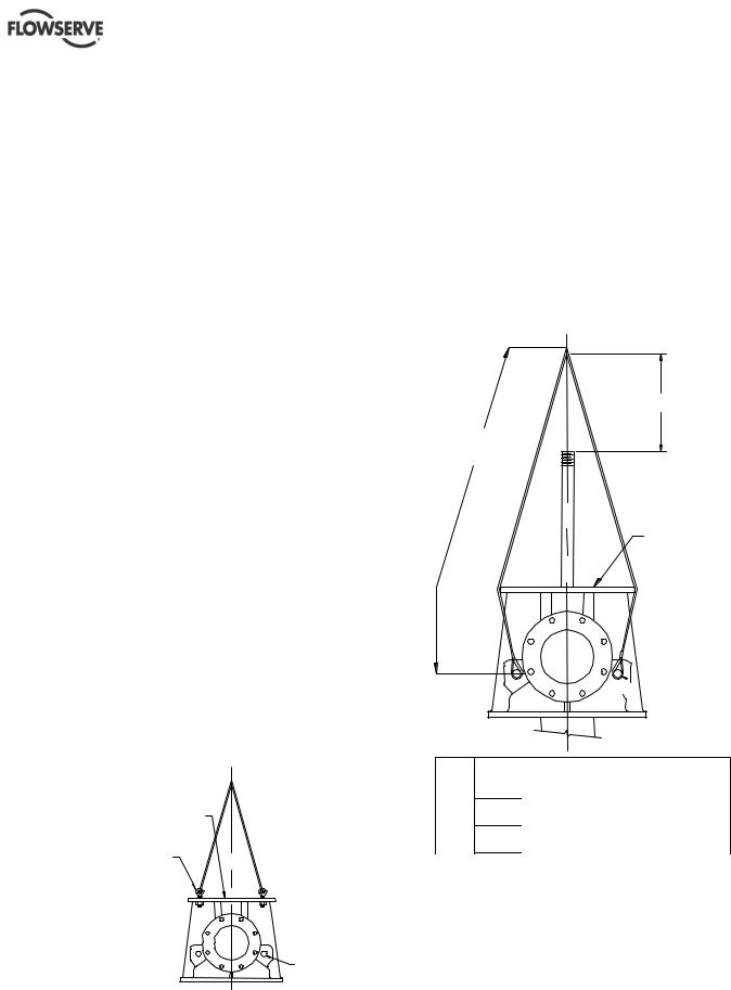
2.3.3Lifting of fabricated discharge heads with
or without the pump
If the pump is supplied with a fabricated discharge head use 2 point or 3 point method of lifting as shown in the details provided in 2.3.3.1 & 2.3.3.2. This method is applicable to the lifting of discharge heads with or without the pump.
Page 10 of 76 |
flowserve.com |
VERTICAL TURBINE PUMPS (VTPS) CENTRIFUGAL PUMPS ENGLISH 71569224 – 10-13
2.3.3.1Two point lifting of fabricated discharge head types TF, UF & HFH (with or without pump attached)
"L" |
FABRICATED WITH |
|
2 POINT LIFTING |
||
|
50 mm (2in.) HOLE
2.3.4Lifting of bowl assembly only
Clamp the bowl assembly and center the lifting hook for lifting and lowering the assembly into the sump/suction barrel.
a)Lower the bowl assembly until the clamp extensions rest on the foundation (use appropriate supports).
b)Build the very first section of the column piping, and lower the entire assembly to assemble the next column section.
c)Continue to build until it is ready for discharge head assembly.
d)Install the discharge head.
e)Assemble the motor.
Example: Lifting of bowl assembly
|
Fabricated heads with discharge size mm (in.) |
|||
|
100-200 |
250-600 |
700-900 |
|
|
(4-8) |
(10-24) |
(28-36) |
|
|
|
|
|
|
Pin |
32 (1.25) |
38 (1.50) |
44 (1.75) |
|
Dia. |
||||
|
|
|
||
Weight |
<2300 (5000) |
<4500 (10000) |
<6800 (15000) |
|
|
|
|
|
|
2.3.3.2Three point lifting of fabricated discharge head of type HFL (with or without pump attached)
HFL STYLE FABRICATED
WITH 3 POINT LIFTING
Page 11 of 76 |
flowserve.com |
VERTICAL TURBINE PUMPS (VTPS) CENTRIFUGAL PUMPS ENGLISH 71569224 – 10-13
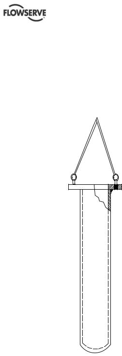
2.3.5Lifting of suction barrel
Suction barrel (also referred as ‘Can’) is always supplied separately and has to be installed into the sump first. Install eyebolts on the flange of the suction barrel and attach slings and straps to bring the suction barrel to a vertical position. Move the barrel for installation. Provide hand support to prevent the suction barrel from swaying during movement.
Example: Lifting of suction barrel
SUCTION BARREL (CAN)
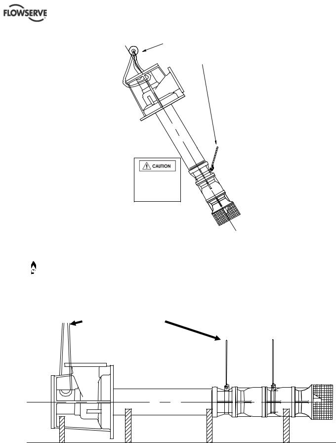
2.3.6 Lifting of fully assembled pumps
If the pump is fully assembled, it has to be adequately strapped and supported at least two places before it can be lifted from the shipping crate and moved to the installation site. See details shown. Same rules are applicable when the pump is pulled out from the sump and moved to another location.
Page 12 of 76 |
flowserve.com |
VERTICAL TURBINE PUMPS (VTPS) CENTRIFUGAL PUMPS ENGLISH 71569224 – 10-13
Pump must be supported at least two places when lifted.
Do not use chains to wrap around.
Two (2) cranes are required
 Examples shown here are for illustration only. See section 2.3 1~2.3.6 for specific lifting instructions based on design variations. The pumps vary in weight, length and physical appearances from the types shown here.


 Therefore, before lifting is attempted, exercise caution to prevent any injuries or loss of life.
Pump must be supported at least two places when lifted.
Do not use chains to wrap around.
Page 13 of 76 |
flowserve.com |

VERTICAL TURBINE PUMPS (VTPS) CENTRIFUGAL PUMPS ENGLISH 71569224 – 10-13
2.4 Storage
 Store the pump in a clean, dry location away from vibration. Leave piping connection covers in place to keep dirt and other foreign material out of pump casing. Turn the pump at frequent intervals to prevent brinelling of the bearings and the seal faces, if fitted, from sticking.
2.4.1Inspection before storage
a)Inspect the preservative coating/painted surfaces on the various parts. Touch up the areas, If necessary.
b)Inspect all covers over pump openings and piping connections. If found damaged, remove the covers and inspect interiors of the opening for any deposits of foreign materials or water.
c)If necessary, clean and preserve the interior parts as noted above to restore the parts to the "as shipped" condition. Replace covers and fasten securely.
d)Exercise caution with pumps exposed to weather. Containers are not leak proof. Parts may be coated with a residual amount of protective coating, which will wash away if exposed to elements.
2.4.2 Short term storage (up to 6 months)
Follow the steps given in section 2.4.1. Select a storage space so that the unit will not be subjected to excess moisture, extreme weather conditions, corrosive fumes, or other harmful conditions.
Driver storage instructions: Check driver manufacturer’s User Instructions
2.4.3Long term or extended storage
If a situation arises for a long-term storage, ( more than 6 months) please contact Flowserve for special storage instructions and warranty related information.
2.5 Recycling and End of Product Life
At the end of the service life of the product or its parts, the relevant materials and parts should be recycled or disposed of using an environmentally acceptable method and local regulations. If the product contains substances which are harmful to the environment, these should be removed and disposed of in accordance with current regulations. This also includes the liquids and or gases in the "seal system" or other utilities.
 Make sure that hazardous substances or toxic fluids are disposed of safely and that the correct
personal protective equipment is used. The safety specifications must be in accordance with the current regulations at all times.
3 DESCRIPTION
Should questions arise concerning the pump, Flowserve pump division will require the complete serial number to be of assistance. The serial number is stamped on a metal nameplate affixed to the discharge head assembly. The driver will have a separate nameplate attached to it. If you are requesting information on the driver, please provide both the driver serial number and the pump serial number for Flowserve representative.
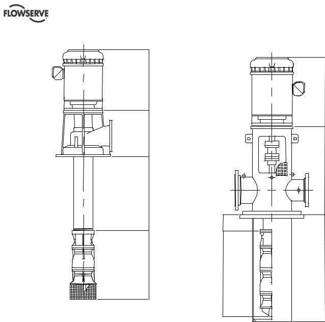
3.1 Configuration
VTPs, are engineered pumps as:(a) Wet pit type and
(b) suction barrel (can) type pumps. Most pumps are built with customer specific features and for applications such as water pumping stations, deep wells, storm water service, industrial and cryogenic applications. The pumps vary in size, impeller types and length, whether it is an open shaft or enclosed shaft designs and type of discharge head used.
Page 14 of 76 |
flowserve.com |
VERTICAL TURBINE PUMPS (VTPS) CENTRIFUGAL PUMPS ENGLISH 71569224 – 10-13
3.1.1 Sump and deep well VTP 3.1.2 Suction barrel (Can) VTP
DRIVER |
|
|
|
DRIVER |
|
DISCHARGE |
|
|
HEAD |
|
|
ASSEMBLY |
|
|
|
DISCHARGE |
|
|
HEAD |
|
|
ASSEMBLY |
|
COLUMN |
|
|
ASSEMBLY |
|
|
|
COLUMN |
|
|
ASSEMBLY |
|
BOWL |
SUCTION |
|
ASSEMBLY |
||
BARREL |
||
|
(CAN) |
|
|
BOWL |
|
|
ASSEMBLY |
3.1.3 Most common VTP models
The VTP configurations shown in sec 3.1.1 and 3.1.2 are typical for variety of VTP models with the bowl assembly types such as EB, EG, EH, EJ, EK, EL, EM, EN, EP, EQ, SK, SL, SN, SP, SR, ST, & AV. The impeller models in each of these pumps are designated separately (see section 3.2 for more details) and the pump sizes could vary from 150mm (6 in) to 1300 mm (52 in.). The size expressed is in terms of nominal bowl diameter and is always in inches.
 Some units will not require a column assembly. In such cases, the bowl assembly is connected directly to the discharge head. Vertical turbine pumps can have single or multiple stages.
Page 15 of 76 |
flowserve.com |
VERTICAL TURBINE PUMPS (VTPS) CENTRIFUGAL PUMPS ENGLISH 71569224 – 10-13
3.2 Nomenclature
The pump size/ serial number will be engraved on the nameplate typically as below: The nameplate is attached to the discharge head assembly.
3.2.1Bowl assembly nomenclature
12 E J H-3
Nominal Bowl Diameter-inches
Impeller Type (A or E or S)
A=Axial, E=Enclosed, S=Semi-open
Bowl Model Types
B,J,K,H,L,M,N,P,Q,R,T,V….
Impeller Model Designation
L, M, H, Y…..
No. of Stages
The typical nomenclature above is the general guide to the VTP configuration description. Identify the actual pump size and serial number from the pump nameplate. The driver will have a separate nameplate attached it.
3.2.2 Discharge head nomenclature
Consists of alphanumeric code as follows. Examples: 8W16, 10HF20, 6TF16,…….
10 HF 20
Nominal driver base diameter in inches
Discharge head type (see details below)
Nominal discharge diameter in inches
W = Cast headfor horizontal above the ground discharge HF = Fabricated head for above the ground discharge
TF & LF = Fabricated heads with base flange
UF = Fabricated head for below ground discharge
HFL = Fabricated head for above ground discharge - Low H.P HFH = Fabricated head for above the ground discharge -High H.P.
Please see section 3.2.2.1 for discharge head types and identification.
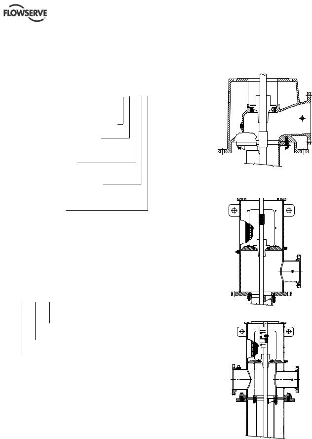
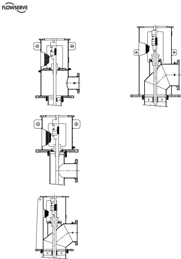
3.2.2.1Types of discharge heads
Typical discharge head types. Details (a) thru (g).
a) W type cast discharge head
b)HF type fabricated discharge head (Typically with square base plate)
c) TF type fabricated discharge head
Page 16 of 76 |
flowserve.com |
VERTICAL TURBINE PUMPS (VTPS) CENTRIFUGAL PUMPS ENGLISH 71569224 – 10-13
d)LF type fabricated discharge head
(Typically with a circular base plateANSI type. Also available with suction barrel mounting)
e) UF type fabricated discharge head
f)HFL type fabricated discharge head
g) HFH type fabricated discharge head
 The discharge heads shown in section 3.2.2.1 (a) thru (g) are for illustration only. The shaft and coupling arrangements vary. For the actual configuration of the pump that has been purchased, please refer to the drawings supplied with the pump or order specific sectionals from Flowserve.
3.3 Design of Major Parts
 Please refer to appendix for Europump part number equivalents
3.3.1Drivers
A variety of drivers may be used, however, electric motors are most common. For the purposes of this manual, all types of drivers can be grouped into two categories.
a)Hollow shaft drivers: where the head shaft extends through a tube in the center of the rotor and is connected to the driver by a clutch assembly at the top of the driver.
b)Solid shaft drivers: where the rotor shaft is solid and projects below the driver-mounting base. This type driver requires an adjustable coupling for connecting to the pump.
3.3.2 Discharge Head Assembly
(See also section 3.2.2.1)
The discharge head supports the driver and bowl assembly as well as supplying a discharge connection in most cases.
Page 17 of 76 |
flowserve.com |
VERTICAL TURBINE PUMPS (VTPS) CENTRIFUGAL PUMPS ENGLISH 71569224 – 10-13
A shaft sealing arrangement is located in the discharge head to seal the shaft at its exit from the liquid chamber.
The shaft seal will usually be either a mechanical seal assembly or stuffing box with an open lineshaft or a tube-packing box with an enclosed lineshaft.
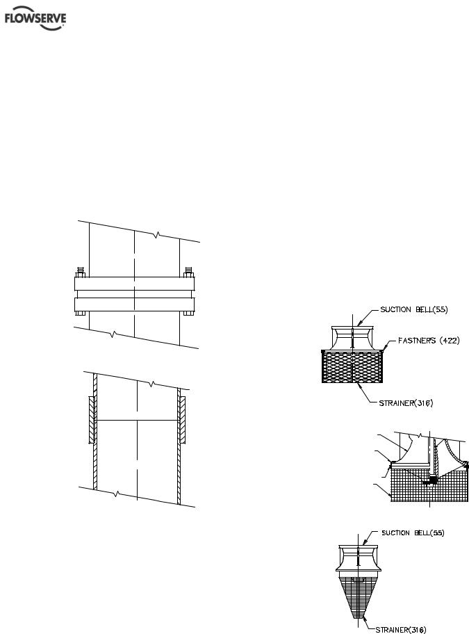
3.3.3Column assembly
The column assembly consists of column pipe, which connects the bowl assembly to the discharge head and carries the pumped fluid to the discharge head. Houses and supports the shaft and may contain bearings. Typical column assemblies are:
a) flanged column assembly
b) threaded column assembly: from 100 mm~355 mm (4~14 in.) sizes only.
The column supports shaft assembly, that is either
a)Open lineshaft construction utilizing the fluid being pumped to lubricate the lineshaft bearings.
Or
b)Enclosed lineshaft construction has an enclosing tube around the lineshaft and utilizes oil or other fluid to lubricate the lineshaft bearings.
The shafts are threaded or key coupled with thrust stud design or clamp ring design.
See sectional drawings supplied with the pump for exact column assembly details as per the order. The size and configuration vary depending upon the specific order requirements and application criteria.
3.3.4Bowl assemblies
The bowl assembly consists of impellers rigidly mounted on the pump shaft coupled to an electric motor. Impellers are cast wheels with multiple diffuser vanes and are generally coated to meet the hydraulic requirements. See section 8.0 for cross sectional and part details.
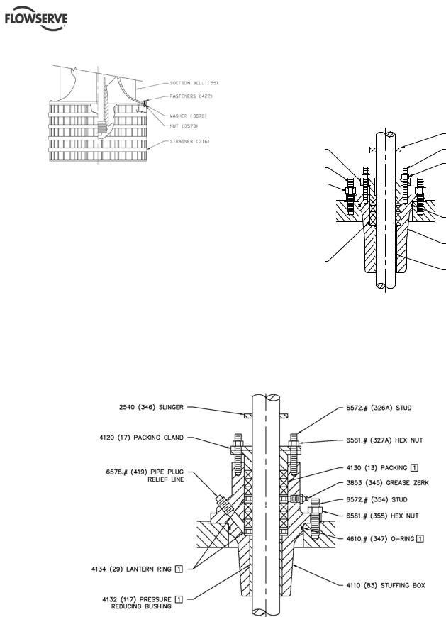
3.3.5Suction strainers
VTPs can also be fitted with strainers [316] to prevent foreign particles from entering the pump. The type of strainers and the mesh size depends on the application. Examples are shown below. Strainers are fastened [422] directly to the suction bell [55] or attached using clips [421]. Cone shaped strainers are provided with internal or external threads to attach it to the main assembly.
a) Slip-on strainer
b) Clip-on strainer
SUCTION BELL (55)
CLIP (421)
CAP SCREW (422) |
STRAINER (316) |
c) Cone (threaded) strainer
Page 18 of 76 |
flowserve.com |
VERTICAL TURBINE PUMPS (VTPS) CENTRIFUGAL PUMPS ENGLISH 71569224 – 10-13
d) Bolt on strainer
3.3.6Impellers
VTP’s are supplied with enclosed, or semi open impeller types. Impellers are low, medium and high capacity type designed for maximum coverage of all VTP applications. Impellers are cast and machined to match each order and to provide required surface finish to achieve hydraulic characteristics. Impellers are dynamically balanced and held in position on the shaft by a tapered lock collet or split ring and key.
3.3.7Stuffing box
Some VTPs are fitted with stuffing boxes. In such cases, stuffing boxes are normally adequate for working pressures up to 20.7 bar (300 psi). Refer to stuffing box User Instructions for specifications.
3.3.7.1Low pressure stuffing box
This type of packing box is fitted on to an open lineshaft for pressures less than 6.5 bar (100 psi) and used only on W-type discharge heads (see Section 3.2.2.1 to see for W type discharge head detail).
|
SLINGER (346) |
(17) PACKING GLAND |
STUD (326A) |
|
|
(354) STUD |
HEX NUT (327A) |
(355) HEX NUT |
|
|
O-RING (347) |
|
STUFFING BOX (83) |
(13) PACKING SET |
|
|
PRESSURE |
|
REDUCING |
|
BUSHING (117) |
3.3.7.2High pressure stuffing box
This type of packing box is fitted on to an open lineshaft for pressures up to 20 bar (300 psi) uses six rings of packing with two lantern rings and allows grease lubrication.
Page 19 of 76 |
flowserve.com |

VERTICAL TURBINE PUMPS (VTPS) CENTRIFUGAL PUMPS ENGLISH 71569224 – 10-13
3.3.7.4Extra high pressure stuffing box
In cases where the pressures are expected to cross 20 bar (300 psi) up to 65 bar (1000 psi), extra highpressure stuffing box is used.
3.3.8Mechanical shaft seal
VTP’s can also be fitted with a mechanical seal. The requirement to fit the mechanical seal to be provided at the time of contract.
Page 20 of 76 |
flowserve.com |
VERTICAL TURBINE PUMPS (VTPS) CENTRIFUGAL PUMPS ENGLISH 71569224 – 10-13
3.3.8Accessories
Accessories may be fitted when specified by the customer.
3.4 Performance and Operation Limits
This product has been selected to meet the specifications of the purchase order. See section 1.5.
The following data is included as additional information to help with the installation. It is typical and factors such as temperature, materials and seal type may influence this data. If required, a definitive statement for your particular application can be obtained from Flowserve.
3.4.1Operating limits
Pumped liquid temperature |
5 ºC (40 ºF) to +80 ºC (176 ºF) |
limits* |
|
Maximum ambient |
Up to +40 ºC (104 ºF) |
temperature* |
|
Maximum pump speed |
refer to the nameplate |
*Subject to written agreement from Flowserve. Special designs and materials may be available for pumps operating above and below these specified limits. Contact Flowserve for upgrade options available for your specific application.
4 INSTALLATION
 Equipment operated in hazardous locations must comply with the relevant explosion protection regulations. See section 1.6.4, Products used in potentially explosive atmospheres.
4.1 Location
When equipment has been in storage for greater than 6 months, a complete inspection should be conducted in accordance with section 2.4.3. The pump should be located to allow room for access, ventilation, maintenance and inspection with ample headroom for lifting and should be as close as practicable to the supply of liquid to be pumped. Refer to the general arrangement drawing for the pump set.
4.1.1Inspection prior to installation
Six months prior to the scheduled installation date, a Flowserve Pump Division representative is to be employed to conduct an inspection of the equipment and the facility. If any deterioration of equipment is noticed, the Flowserve Pump Division representative may require a partial or complete dismantling of the equipment including restoration and replacement of some components.
4.2 Preparation
The pump should be located to allow room for access, ventilation, maintenance and inspection with ample headroom for lifting and should be as close as practicable to the supply of liquid to be pumped.
Refer to the general arrangement drawing for the pump dimensions and details.
4.2.1General installation check-list
The following checks should be made before starting actual installation.
a)Make sure that motor nameplate ratings and the power supply system match correctly.
b)Check the sump depth and pump length matchup.
c)Check the liquid level in the sump.
d)Check the installation equipment to be sure that it will safely handle the pump weight and size.
e)Check all pump connections (bolts, nuts etc) for any shipping and handling related problems.
 Always support shafting in at least three places when lifting or installing. No installation should be attempted without adequate equipment necessary for a successful installation.
On hollow shaft drivers, check the clutch size against the shaft size, which must go through the clutch
On solid shaft drivers, check the motor shaft size against the coupling bore size
 Apply thread lubricant sparingly to male shaft threads only at the time of making up shaft connection. Excess lubricant should be avoided.
 Always check motor rotation before connecting driver to pump. Reserve rotation due to improper motor direction can cause extensive damage to the pump.
4.3 Foundation/Anchor Bolts
 There are many methods of installing pump units to their foundations. The correct method depends on the size of the pump unit, its location and vibration limitations. Non-compliance with the
Page 21 of 76 |
flowserve.com |
VERTICAL TURBINE PUMPS (VTPS) CENTRIFUGAL PUMPS ENGLISH 71569224 – 10-13
provision of correct foundation and installation may lead to failure of the pump and, as such, would be outside the terms of the warranty.
The foundation must consist of material that will afford rigid support to the discharge head and will absorb expected stresses that may be encountered in service.
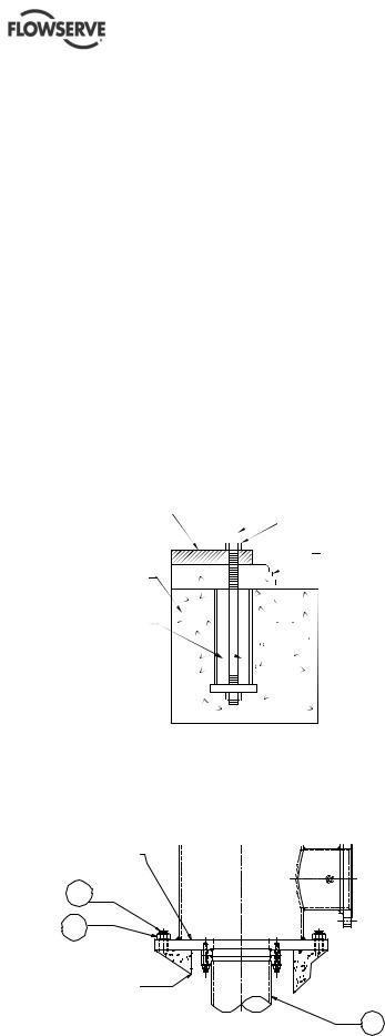
Concrete foundations should have anchor bolts installed in sleeves that allow alignment and have holes in the mounting plate as illustrated in the detail below. Sleeve should be filled with non-bonding moldable material after sleeve is set in place.
When a suction barrel is supplied as in the case of the type "TF" discharge head, the suction vessel must provide permanent, rigid support for the pump and motor.
 All foundation / anchor bolt recommendations should be verified by prevailing industry standards.
Detail of a typical foundation bolt, grouted.
MOUNTING PLATE |
|
|
|
|
|
|
|
ANCHOR BOLT |
|
|
|
|
|
||||
|
|
|
|
|
|
|||
|
|
|
|
|
|
|
|
NUT |
|
|
|
|
|
|
|
|
GROUT |
FOUNDATION |
NON-BONDING |
MOLDABLE MATERIAL |
4.3.1Leveling of pumps mounted on the discharge head flange
Example of a typical discharge head with the mounting flange
DISCHARGE |
HEAD FLANGE |
372 |
373 |
CONCRETE |
101 |
Some wet pit pumps are installed directly by using the flange that comes as an integral part of the discharge head. The pump is lowered into the pit and aligned with the anchor bolts [372].
The mounting flange is shimmed to achieve required level by using a precision machinist’s level. The pump is to be leveled to within 0.16 mm/m
(0.002 in./ft). The data to be recorded for future reference. Anchor bolt nuts [373] are tightened sufficient enough to hold down the pump in place.
Grout is poured and allowed to set for at least 72~80 hours (cure as required) before any further work is done on the pump.
 If leveling nuts are used to level the base, they must be backed off as far as possible prior to grouting.
Always shim near foundation bolts and then back off the leveling nuts. Now tighten the foundation bolts. If done otherwise there is a risk of significantly lowering the structural natural frequency that could result in separation of the base from the grout.
 Directly mounted pumps are not user friendly for service. Re-installation of these pumps requires re-leveling and re-grouting.
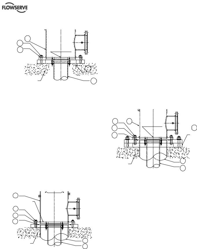
4.3.2Leveling of pumps mounted on a
soleplate and the soleplate is grouted
Some pumps are mounted on a separate plate known as soleplate [23]. In such cases, the level shall be set with a master level or a precision machinist’s level. The mounting surface needs to be leveled to within 0.16 mm/m (0.002 in./ft).
The level should not exceed 0.125 mm (0.005 in.) elevation difference taken on any two points on the individual soleplate. Accurate shimming and grouting of the soleplate is very important. Record the leveling data for future reference. Grout the soleplate and allow to set at least 72~80 hours (cure as required) before the pump is lowered into the pit. Align the discharge head boltholes with the anchor bolts [372].
Check and adjust the pump level to within
0.16 mm/m (0.002 in./ft) with respect to the soleplate and torque the nuts [373] to the required level.
Page 22 of 76 |
flowserve.com |
VERTICAL TURBINE PUMPS (VTPS) CENTRIFUGAL PUMPS ENGLISH 71569224 – 10-13
Example of pump mounted on a soleplate
|
304 |
|
372 |
DISCHARGE |
|
373 |
||
HEAD FLANGE |
|
23 |
|
|
SOLE |
|
CONCRETE |
PLATE |
|
101 |
||
FOUNDATION |
||
|
4.3.3Leveling of pumps with the suction barrel
(also referred as “Can” VTPs)
The suction barrel [315] is first lowered into the pit and aligned with the anchor bolts [372]. The suction barrel flange is leveled by using a master level or a precision machinist’s level. Levels should be taken on the equipment mounting surfaces. The suction barrel flange mounting surface needs to be leveled to within
0.16 mm/m (0.002 in./ft) using shims and grouted.
Allow the grout to set for at least 72~80 hours before the pump is installed. Check the barrel mounting surface level after the grout is set and then proceed with the pump installation. Lower the pump assembly into the pit and align the discharge head flange bolt holes to the anchor bolts [372].
Check and adjust the pump level with respect to the barrel flange to within 0.16 mm/m (0.002 in./ft) and final torque the nuts [373]. The leveling data to be recorded for future reference.
Example of a pump installed with a suction barrel.
304 |
|
DISCHARGE |
|
HEAD FLANGE |
|
372 |
|
373 |
|
374 |
|
CONCRETE |
315 |
|
|
FOUNDATION |
101 |
|
4.3.4Leveling of pumps with suction barrel
mounted on a soleplate
The soleplate [23] is installed on the foundation and aligned with the anchor bolts [372]. Level the soleplate with the help of a machinist’s level to within
0.16 mm/m (0.002 in./ft). Tighten the nuts [373] and grout. Cure and allow grout to set for 72~80 hours. Lower the suction barrel into the pit and level again with respect to the soleplate [23] to within 0.16 mm/m (0.002 in./ft). The level should not exceed 0.125 mm (0.005 in.) elevation difference taken on any two points on the soleplate. The pump [101] is now lowered into the suction barrel and installed. Make sure that the discharge head flange is still in level within 0.16 mm/m (0.002 in./ft) with respect to the suction barrel [315].
Example of pump with a suction barrel mounted on a soleplate
372 |
304 |
DISCHARGE |
|
373 |
|
HEAD FLANGE |
23 |
|
|
||
374 |
|
|
SOLE |
|
|
PLATE |
|
CONCRETE |
|
315 |
|
|
|
||
FOUNDATION |
|
101 |
|
|
|
|
|
4.4 |
Grouting |
|
|
Where applicable, grout in the foundation bolts. After adding pipe work connections and re-checking the coupling alignment, the mounting plate/soleplate should then be grouted in accordance with good engineering practice. If in any doubt, please contact Flowserve service center for advice.
Grouting provides solid contact between the pump unit and foundation that prevents lateral movement of running equipment and dampens resonant vibrations. Care should be taken to ensure maximum surface contact with grout between the pump base, sole plate, suction can and foundation (no voids).
 Foundation bolts should only be fully tightened after the grout has been cured.
Page 23 of 76 |
flowserve.com |
 Loading...