


P-50
Installation
Instructions
Durametallic
®
P-50
Experience In Motion
A cartridge mounted, flexible stator
pusher seal design for general
service applications

2
Congratulations
You have just purchased a reliable, long-life product manufactured by
the leading manufacturer of sealing systems in the world. With proper
installation and operation, this P-50 seal can be a valuable contributor to
your operation by signicantly reducing the mean time between planned
maintenance (MTBPM) of your rotary equipment.
Description
This P-50 seal is a cartridge mounted mechanical seal, designed for
ease of installation and reliable operation. No seal setting dimensions
are required. Removable setting devices provide proper alignment.
The exible stationary face design compensates for inadvertent mis-
alignment of the seal chamber face. Multiple springs provide uniform
face loading and are external of the pumpage, resisting clogging or
hang-up. Installation according to the following steps will assure long
trouble free life of the P-50 seal.
1 Equipment Check
1.1 Follow plant safety regulations prior to equipment disassembly:
• Lock out motor and valves.
• Wear designated personal safety equipment.
• Relieve any pressure in the system.
• Consult plant MSDS les for hazardous material regulations.
1.2 Disassemble equipment in accordance with equipment
manufacturer's instructions to allow access to seal installation
area.
1.3 Remove existing mechanical seal and gland or compression
packing and packing gland.
1.4 Make sure the shaft or sleeve and the seal housing face are
clean and free of burrs, cuts, dents, or corrosion that might cause
leakage past the sleeve gasket O-ring or gland gasket. Replace
worn shaft or sleeve. Remove sharp edges from keyways and
threads.
The images of parts shown in these instructions may differ visually from the actual
parts due to manufacturing processes that do not affect the part function or quality.
3
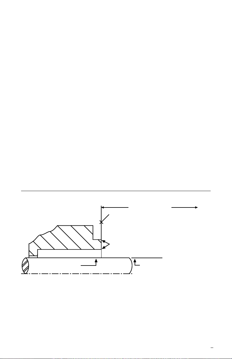
Seal Chamber Requirements Figure 1
1.5 Check equipment dimensions to ensure that they are within the
dimensions shown in Figures 1 and 2. Critical dimensions include
shaft or sleeve OD (A), a chamber depth of at least 25.4 mm
(1.000 inch), minimum and maximum seal housing bore (B), and
the minimum distance to the rst obstruction (F).
1.6 Check gland bolting to ensure that bolt diameter and bolt circle
conform to he dimensions shown in Figure 2.
1.7 Handle the P-50 with care, it is manufactured to precise
tolerances. The stationary and rotating sealing faces are of
special importance. They are lapped at to within three light
bands (34.8 millionths of an inch). Keep the seal faces perfectly
clean at all times.
To first obstruction
Face of seal housing to be square to the
axis of the shaft to within 0.0005 mm/mm
(0.0005 inch/inch) of seal chamber bore TIR
and have a 1.6
μm (63 μinch) R finish or better
a
Gland pilot can be at either of these
register locations, concentric to within
0.125 mm (0.005 inch) of shaft or
sleeve OD TIR
Seal housing bore to have 3.2 μm
(125 μinch) R finish or better
Sleeve or shaft finish to be
0.8 μm (32 μinch) R or better
a
a
• Bearings must be in good condition
• Maximum lateral or axial movement of shaft (end play) = 0.25 mm (0.010 inch) TIR
• Maximum shaft runout at face of seal housing = 0.05 mm (0.002 inch) TIR
• Maximum dynamic shaft deflection at seal housing = 0.05 mm (0.002 inch) TIR
Shaft or sleeve OD
+0.000 mm (+0.000 inch)
-0.050 mm (-0.002 inch)
+0.000 mm (+0.000 inch) API 610/682
-0.025 mm (-0.001 inch) DIN/ISO
ANSI
4
1.000 1.625 2.000 1.50 1.750 1.88 2.00 3.69 - 3.75 1.19 2.75 2.88
1.125 1.750 2.125 1.62 1.875 1.88 2.00 3.81 - 3.88 1.19 2.88 3.00
1.250 1.875 2.250 1.75 2.000 1.88 2.00 4.19 - 4.25 1.19 3.00 3.12
1.375 2.000 2.375 1.88 2.125 1.88 2.00 4.19 - 4.25 1.19 3.12 3.25
1.500 2.250 2.625 2.12 2.375 1.88 2.00 4.69 - 4.75 1.19 3.44 3.56
1.625 2.375 2.750 2.25 2.500 1.88 2.00 4.69 - 4.75 1.19 3.56 3.69
1.750 2.500 2.875 2.38 2.625 1.88 2.00 4.94 - 5.00 0.96 3.62 3.75
1.875 2.625 3.000 2.50 2.750 1.88 2.00 4.94 - 5.00 1.19 3.75 3.88
2.000 2.750 3.125 2.62 2.875 1.88 2.00 5.06 - 5.12 1.19 3.94 4.06 4.25
2.125 2.875 3.250 2.75 3.000 1.88 2.00 5.94 - 6.00 1.06 4.06 4.19 4.38
2.250 3.000 3.375 2.88 3.125 1.88 2.00 6.44 - 6.50 1.19 4.19 4.31 4.50
2.375 3.250 3.625 3.12 3.375 2.00 2.12 6.31 - 6.38 1.19 4.44 4.56 4.75
2.500 3.375 3.750 3.25 3.500 2.00 2.12 6.56 - 6.62 1.00 4.56 4.69 4.88
2.625 3.500 3.875 3.38 3.625 2.00 2.12 7.19 - 7.25 1.19 4.69 4.81 5.00 5.25
2.750 3.625 4.000 3.50 3.750 2.00 2.12 7.69 - 7.75 1.19 4.81 4.94 5.12 5.38
2.875 3.750 4.125 3.62 3.875 2.00 2.12 7.94 - 8.00 1.19 4.94 5.06 5.25 5.50
3.000 3.875 4.250 3.75 4.000 2.00 2.12 8.06 - 8.12 1.19 5.06 5.19 5.38 5.62
3.125 4.000 4.375 3.88 4.125 2.00 2.12 8.19 - 8.25 1.19 5.19 5.31 5.50 5.75
3.250 4.125 4.500 4.00 4.250 2.00 2.12 8.31 - 8.38 1.19 5.31 5.44 5.62 5.88
3.375 4.250 4.625 4.12 4.375 2.00 2.12 8.44 - 8.50 1.19 5.44 5.56 5.75 6.00
3.500 4.375 4.750 4.25 4.500 2.00 2.12 8.56 - 8.62 1.19 5.56 5.69 5.88 6.12
3.625 4.500 4.875 4.38 4.625 2.00 2.12 8.69 - 8.75 1.19 5.69 5.81 6.00 6.25
3.750 4.625 5.000 4.50 4.750 2.00 2.12 8.81 - 8.88 1.19 5.81 5.94 6.12 6.38
3.875 4.750 5.125 4.62 4.875 2.00 2.12 8.94 - 9.00 1.19 5.94 6.06 6.25 6.50
4.000 4.875 5.250 4.75 5.000 2.00 2.12 8.94 - 9.00 1.19 6.06 6.19 6.38 6.62
A
Shaft & B B C D E F G H Min. Bolt Circle for Bolt Dia.
Seal Size (Min) (Max) .375 .500 .625 .750
Dimensional Data
(inches)
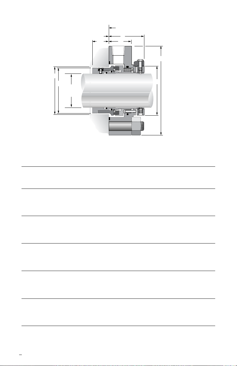
Figure 2
P-50
F minimum distance
to first obstruction
E
H
1.00 inch Minimum Box Depth
.88
inch
G
D
B
C
A
Shaft & Seal
Size
 Loading...