


USER INSTRUCTIONS
LPC Compact Actuator Series |
Installation |
Single Acting & Double Acting |
Operation |
FCD LFENIM0002-00-AQ – 07/14 |
Maintenance |
|
|
|
|
Experience In Motion

|
|
LPC Compact Actuator Series FCD LFENIM0002-00-AQ 07/14 |
|
Contents |
|
||
1 |
Standard Information |
3 |
|
|
1.1 |
General Usage |
3 |
|
1.2 |
Terms Concerning Safety |
3 |
|
1.3 |
Protective Clothing |
4 |
|
1.4 |
Qualified Personnel |
4 |
|
1.5 |
Other General Requirements for In-Plant Installation |
4 |
|
1.6 |
Spare Parts |
4 |
|
1.7 |
Service/Repair |
4 |
|
1.8 |
Storage |
5 |
|
1.9 |
Valve and Actuator Variations |
6 |
|
1.10 Unpacking |
6 |
|
2 |
Installation Instructions |
7 |
|
|
2.1 |
Valve and Actuator Check |
7 |
|
2.2 |
Connection With Valve and Mounting Kit |
8 |
|
2.3 |
Travel-stop Bolts and Accessories |
8 |
|
2.4 |
Pneumatic Supply Fluids |
8 |
|
2.5 |
Initial Operation |
9 |
|
2.6 |
Fail Open and Fail Close Configuration |
9 |
3 |
Field Conversion |
11 |
|
4 |
Maintenance Instructions |
12 |
|
|
4.1 |
General Disassembly Instructions |
12 |
|
4.2 |
Spring Container and Pneumatic Cylinder Maintenance |
12 |
|
4.3 |
Housing and Scotch Yoke Maintenance |
14 |
5 |
Troubleshooting |
15 |
|
6 Disposal of Decommissioned Actuators |
17 |
||
7 |
Annex |
18 |
|
Figures |
|
||
Figure 1: Actuator’s Position on the Wooden Pallet |
5 |
||
Figure 2: Position of the Output Shaft |
5 |
||
Figure 3: Standard Data Plate Position |
7 |
||
Figure 4: Nameplate Sample |
7 |
||
Figure 5: Actuator Configuration: Fail Close – Fail Clockwise – Single Acting |
9 |
||
Figure 6: Actuator Configuration: Fail Open – Fail Counter Clockwise – Single Acting |
9 |
||
Figure 7: Double Acting Actuator Configuration – Close Position |
10 |
||
Figure 8: Double Acting Actuator Configuration – Open Position |
10 |
||
Figure 9: Fail Close Configuration With Valve |
10 |
||
Figure 10: Fail Open Configuration With Valve |
10 |
||
Figure 11: Model Selection Table |
18 |
||
Figure 12: Seals Material |
18 |
||
Figure 13: Weights and Dimensions Table – Single Acting – Symmetric and Canted |
20 |
||
Figure 14: Weights and Dimensions Table – Double Acting – Symmetric and Canted |
21 |
||
Figure 15: Exploded View |
23 |
||
2

LPC Compact Actuator Series FCD LFENIM0002-00-AQ 07/14
1 Standard Information
1. Using Flowserve Valves, Actuators and Accessories Correctly
1.1 General Usage
The following instructions are designed to assist in unpacking, installing and performing maintenance as required on Flowserve products. Product users and maintenance personnel should thoroughly review this bulletin prior to installing, operating or performing any maintenance.
In most cases Flowserve actuators and accessories are designed for specific applications with regard to medium, pressure and temperature. For this reason they should not be used in other applications without first contacting the manufacturer.
1.2 Terms Concerning Safety
The safety terms DANGER, WARNING, CAUTION and NOTE are used in these instructions to highlight particular dangers and/or to provide additional information on aspects that may not be readily apparent.
c |
DANGER: indicates that death, severe personal injury and/or substantial property damage will occur if proper |
|
precautions are not taken. |
aWARNING: indicates that death, severe personal injury and/or substantial property damage can occur if proper precautions are not taken.
aCAUTION: indicates that minor personal injury and/or property damage can occur if proper precautions are not taken.
NOTE: indicates and provides additional technical information, which may not be very obvious, even to qualified personnel.
Compliance with other, not particularly emphasized notes, with regard to transport, assembly, operation and maintenance and with regard to technical documentation (e.g. in the operating instruction, product documentation or on the product itself) is essential, in order to avoid faults, which in themselves might directly or indirectly cause severe personal injury or property damage.
3
flowserve.com

LPC Compact Actuator Series FCD LFENIM0002-00-AQ 07/14
1.3 Protective Clothing
Flowserve products are often used in problematic applications (e.g. extremely high pressures, dangerous, toxic or corrosive media). When performing service, inspection or repair operations always ensure, that the valve and actuator are depressurized and that the valve has been cleaned and is free from harmful substances. In such cases pay particular attention to personal protection (protective clothing, gloves, glasses etc.).
1.4 Qualified Personnel
Qualified personnel are people who, on account of their training, experience and instruction and their knowledge of relevant standards, specifications, accident prevention regulations and operating conditions, have been authorized by those responsible for the safety of the plant to perform the necessary work and who can recognize and avoid possible dangers.
1.5 Other General Requirements for In-Plant Installation
• Pipelines must be correctly aligned to ensure that the valve is not fitted under tension.
• Flowserve can provide a fire protection system. If not expressly agreed, fire protection must be provided by user.
1.6 Spare Parts
Use only Flowserve original spare parts. Flowserve cannot accept responsibility for any damages that occur from using spare parts or fastening materials from other manufacturers. If Flowserve products (especially sealing materials) have been on store for longer periods check these for corrosion or deterioration before using these products.
1.7 Service/Repair
To avoid possible injury to personnel or damage to products, safety terms must be strictly adhered to. Modifying this product, substituting non-factory parts, or using maintenance procedures other than outlined in this instruction
could drastically affect performance and be hazardous to personnel and equipment, and may void existing warranties. Between actuator and valve there are moving parts. To avoid injury Flowserve provides pinch-point-protection in the form of cover plates, especially where side-mounted positioners are fitted. These protections are according to Machine Directive 2006/42/EC recommendations. If these plates are removed for inspection, service or repair special attention is required. After completing work the cover plates must be refitted. Apart from the operating instructions and the obligatory accident prevention directives valid in the country of use, all recognized regulations for safety and good engineering practices must be followed.
aWARNING: Before products are returned to Flowserve for repair or service, Flowserve must be provided with a certificate which confirms that the product has been decontaminated and is clean. Flowserve will not accept deliveries if a certificate has not been provided (a form can be obtained from Flowserve).
4
LPC Compact Actuator Series FCD LFENIM0002-00-AQ 07/14
1.8 Storage
In many cases Flowserve products are manufactured from stainless steel. Products not manufactured from stainless steel are typically provided with an epoxy resin coating or with other painting systems agreed with the customer. This means that Flowserve products are well protected from corrosion. Nevertheless, in order to maintain good working conditions and a good finish until the actuator is installed on the plant, it is necessary to follow a few rules during the storage period:
•Flowserve products must be stored adequately in a clean, dry environment.
•Ensure that plastic caps are fitted to protect the pneumatic connections and the cable entries, to prevent the ingress of foreign materials. These caps should not be removed until the product is actually mounted into the system.
•If the storage is outdoor, or if long-term storage (more than four months) is necessary, the plastic protection plugs have to be replaced by metal plugs, because the plastic plugs are not weatherproof function, whereas the metal ones guarantee a weatherproof protection.
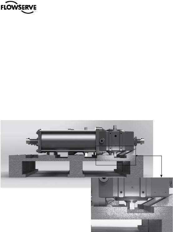
•The actuator must be placed on a wooden pallet, in order to not damage the coupling base and avoid that other surfaces other surfaces rest on the ground.
Figure 1: Actuator’s Position on the Wooden Pallet
Figure 2: Position of the Output Shaft
In case of long-term storage (more than four months), additionally perform the following measures:
•Coat the coupling parts (spool piece base, flanges, bushings, joints) with protective oil or grease.
•If possible, blank off the spool piece base flange by a protection disk.
•Provide a tarpaulin cover or some other means of protection, especially if the storage is outdoor.
•It is important to periodically operate the actuator with filtered, dehydrated and lubricated air while in a storage.
5
flowserve.com

LPC Compact Actuator Series FCD LFENIM0002-00-AQ 07/14
1.9 Valve and Actuator Variations
These instructions cannot claim to cover all details of all possible product variations, nor can they provide information for every possible example of installation, operation or maintenance. This means that the instructions normally include only the directions to be followed by qualified personnel where the product is being used for its defined purpose. If there are any uncertainties in this respect particularly in the event of missing product-related information, clarification must be obtained via the appropriate Flowserve sales office.
1.10 Unpacking
•Each delivery includes a packing slip. When unpacking, check all delivered actuators and accessories using this packing slip.
•Report transport damage to the carrier immediately.
•In case of discrepancies, contact your nearest Flowserve location.
•If necessary, retouch minor damage to the paint coating which may have occurred during transport or storage.
NOTE: When the actuator has ATEX or SIL requirements, ensure that the “LPC Series Safety Manual” (Functional Safety and SIL Certification) and “LPC Series Safety Extract and Instruction Manual” (Explosive Atmosphere Equipment and ATEX Certification) accompany this manual and are refer to equipment for usage.
6
LPC Compact Actuator Series FCD LFENIM0002-00-AQ 07/14
2 Installation Instructions
The LPC range of Limitorque Pneumatic Actuators is a robust, lightweight modular scotch yoke design, available in both spring return and double acting configurations, with a torque range up to 1600 Nm (1180 ft-lb); contact factory for lager size. Available with valve interface in compliance with ISO 5211, or customized upon request.
a WARNING! Actuator operation/pressure limitations must be in accordance with Technical Bulletin (LFENTB0002-00)
2.1 Valve and Actuator Check
c |
DANGER: Before installation check the order no., serial no., and/or the tag no. to ensure that the valve/actuator is |
||||
|
correct for the intended application. |
||||
|
|
|
|
|
|
|
|
|
|
|
|
|
|
|
|
|
|
|
|
|
|
|
|
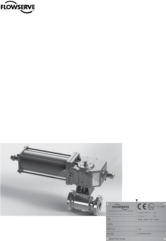
Figure 3: Standard Data Plate Position
Figure 4: Nameplate Sample
Prior to assembly, manually open and close valve (if possible), to ensure freedom of operation. Be sure valve and Limitorque actuator rotate in the same direction and are in the same position (i.e., valve closed, actuator closed). The assembly position of the actuator, with reference to the valve, has to be in accordance with the plant requirements (actuator axis parallel or perpendicular to the pipeline axis).
7
flowserve.com

LPC Compact Actuator Series FCD LFENIM0002-00-AQ 07/14
2.2 Connection With Valve and Mounting Kit
The LPC actuator is usually supplied with the spool piece already assembled. To assemble the actuator onto the valve, perform the following steps:
1.Check the mounting surfaces, the stem adaptor and the spool piece to assure the proper fit. Clean the flange of the valve and spool piece to remove oils and greases since the torque is transmitted by friction. Also remove any rust that may have occurred during the storage.
2.Secure the valve in the closed/open position, if possible, with the stem vertical. Lubricate the valve stem in order to ease the assembly. Place the stem adaptor on the valve stem.
3.Lift the actuator using a proper lifting system. Position the actuator over the valve and lower to engage the stem adaptor to the actuator bore. Continue to lower until the spool piece sits on valve mounting surface. This coupling has to take place without force and only with the weight of the actuator. The mounting bolts (or studs) of the valve should easily fit into the bolt holes of the spool piece without any binding. If needed, turn or stroke the actuator a few degrees and/or adjust the actuator travel-stops.
4.The mounting nuts (or bolts) connecting the base of the spool piece to the valve flange must be evenly tightened according to specific tables, available upon request to Flowserve After Sales Department.
2.3 Travel-stop Bolts and Accessories
All actuated valves require accurate travel-stop adjustments at both ends of the stroke to obtain optimum performance and valve seat life. Adjust the travel-stop bolts of the actuator for the proper open and close valve positions, per valve manufacturer’s recommendations.
The LPC actuators have travel-stop adjustments in both the clockwise and counter-clockwise directions. The
+/- 5-degree adjustment feature provides shaft rotation from 80 to 100 degrees overall. The adjustment of the travelstops is performed in accordance with the following steps. Refer to Figure 15.
•Pneumatic cylinder stop (19): Loosen the hex nut (20) with a proper wrench. Screw or unscrew the stop (19), using a proper Allen key, while keeping the hex nut stationary. Tighten the hex nut.
•Housing stop (19): Loosen the hex nut (20) with a proper wrench. Screw or unscrew the stop (19), using a proper Allen key, while keeping the hex nut stationary. Tighten the hex nut.
Adjust the travel stop bolts of the actuator for the proper open and closed valve positions, per valve manufacturer’s recommendations. Pneumatically stroke the actuator several times to assure proper operation. If the actuator is equipped with a switch, positioner or other accessories, adjusts them at this time.
2.4 Pneumatic Supply Fluids
To prolong actuator life use only clean, dry pneumatic supply fluids. Lubricated fluids are not required; however, they are recommended, particularly for high cycle applications. Do not use lubricated fluids with positioners, as they may damage the positioner.
8
 Loading...