


|
User Instructions Logix 510si - LGENIM0510-01 09/09 |
|
® |
USER INSTRUCTIONS |
|
|
|
|
|
|
|
Logix 510si Series |
Installation |
|
Digital Positioner |
Operation |
|
FCD LGENIM0510-02 12/13 |
Maintenance |
|
|
|
|
Experience In Motion

User Instructions Logix 510si - LGENIM0510-02 12/13
 ®
®
Table of Contents |
Page |
General Information .................................................... |
2 |
Unpacking ................................................................... |
3 |
Logix 510si Overview ................................................. |
4 |
Specifications.............................................................. |
4 |
Principle of Operation ................................................. |
5 |
Tubing ......................................................................... |
5 |
Wiring ......................................................................... |
6 |
Startup ........................................................................ |
7 |
Logix 510si Local Interface Operation.................... |
7 |
Operation of Configuration Dipswitch Setup .......... |
7 |
Setup of the Cal Dipswitches ................................. |
8 |
Quick-Cal Operation ............................................... |
8 |
Factory Reset ......................................................... |
8 |
Error Codes................................................................. |
12 |
Trouble Shooting......................................................... |
14 |
Spare parts ................................................................. |
15 |
Limit switches............................................................. |
15 |
Dimensions ................................................................. |
18 |
1USING FLOWSERVE VALVES, ACTUATORS AND ACCESSORIES CORRECTLY
1.1Using
The following instructions are designed to assist in unpacking, installing and performing maintenance as required on FLOWSERVE products. Product users and maintenance personnel should thoroughly review this bulletin prior to installing, operating or performing any maintenance.
In most cases FLOWSERVE valves, actuators and accessories are designed for specific applications (e.g. with regard to medium, pressure, temperature). For this reason they should not be used in other applications without first contacting the manufacturer.
1.2Terms concerning safety
The safety terms DANGER, WARNING, CAUTION and NOTE are used in these instructions to highlight particular dangers and/or to provide additional information on aspects that may not be readily apparent.
DANGER: indicates that death, severe personal injury and/or substantial property damage will occur if proper precautions are not taken.
WARNING: indicates that death, severe personal injury STOP! and/or substantial property damage can occur if proper
precautions are not taken.
CAUTION: indicates that minor personal injury and/or property damage can occur if proper precautions are not taken.
NOTE: indicates and provides additional technical information, which may not be very obvious even to qualified personnel.
Compliance with other, not particularly emphasised notes, with regard to transport, assembly, operation and maintenance and with regard to technical documentation (e.g. in the operating instruction, product documentation or on the product itself) is essential, in order to avoid faults, which in themselves might directly or indirectly cause severe personal injury or property damage.
1.3Protective clothing
FLOWSERVE products are often used in problematic applications (e.g. extremely high pressures, dangerous, toxic or corrosive mediums). In particular valves with bellows seals point to such applications. When performing service, inspection or repair operations always ensure, that the valve and actuator are depressurised and that the valve has been cleaned and is free from harmful substances. In such cases pay particular attention to personal protection (protective clothing, gloves, glasses etc.).
1.4Qualified personnel
Qualified personnel are people who, on account of their training, experience and instruction and their knowledge of relevant standards, specifications, accident prevention regulations and operating conditions, have been authorised by those responsible for the safety of the plant to perform the necessary work and who can recognise and avoid possible dangers.
1.5Installation
DANGER: Before installation check the order-no, serial-no. and/or the tag-no. to ensure that the valve/ actuator is correct for the intended application.
Do not insulate extensions that are provided for hot or cold services.
Pipelines must be correctly aligned to ensure that the valve is not fitted under tension.
Fire protection must be provided by the user.
2

User Instructions Logix 510si - LGENIM0510-02 12/13
 ®
®
1.6Spare parts
Use only FLOWSERVE original spare parts. FLOWSERVE cannot accept responsibility for any damages that occur from using spare parts or fastening materials from other manufactures. If FLOWSERVE products (especially sealing materials) have been on store for longer periods check these for corrosion or deterioration before using these products. Fire protection for FLOWSERVE products must be provided by the end user.
1.7Service / repair
To avoid possible injury to personnel or damage to products, safety terms must be strictly adhered to. Modifying this product, substituting nonfactory parts, or using maintenance procedures other than outlined in this instruction could drastically affect performance and be hazardous to personnel and equipment, and may void existing warranties. Between actuator and valve there are moving parts. To avoid injury FLOWSERVE provides pinch-point-protection in the form of cover plates, especially where side-mounted positioners are fitted. If these plates are removed for inspection, service or repair special attention is required. After completing work the cover plates must be refitted.
Apart from the operating instructions and the obligatory accident prevention directives valid in the country of use, all recognised regulations for safety and good engineering practices must be followed.
WARNING: Before products are returned to STOP! FLOWSERVE for repair or service FLOWSERVE must be provided with a certificate which confirms that the product has been decontaminated and is clean. FLOWSERVE will not accept deliveries if a certificate has not been provided (a form can be obtained from
FLOWSERVE).
1.8Storage
In most cases FLOWSERVE products are manufactured from stainless steel. Products not manufactured from stainless steel are provided with an epoxy resin coating. This means that FLOWSERVE products are well protected from corrosion. Nevertheless FLOWSERVE products must be stored adequately in a clean, dry environment. Plastic caps are fitted to protect the flange faces to prevent the ingress of foreign materials. These caps should not be removed until the valve is actually mounted into the system.
1.9Valve and actuator variations
These instructions cannot claim to cover all details of all possible product variations, nor in particular can they provide information for every possible example of installation, operation or maintenance. This means that the instructions normally include only the directions to be followed by qualified personal where the product is being used for is defined purpose. If there are any uncertainties in this respect particularly in the event of missing product-related information, clarification must be obtained via the appropriate FLOWSERVE sales office.
2UNPACKING
Each delivery includes a packing slip. When unpacking, check all delivered valves and accessories using this packing slip.
Report transport damage to the carrier immediately.
In case of discrepancies, contact your nearest FLOWSERVE location.
3

User Instructions Logix 510si - LGENIM0510-02 12/13
 ®
®
3LOGIX 510si OVERVIEW
The Logix 510si is a two-wire, 4-20 mA input digital valve positioner. The Logix 510si positioner controls singleacting actuators with linear and rotary mountings. The Logix 510si is completely powered by the 4-20 mA input signal. The minimum input signal required to function is 3,6 mA.
4 |
SPECIFICATIONS |
|
|
|
Table 1: Input Signal |
|
|
|
|
|
|
|
||
|
|
|
|
|
Input Signal Range |
|
4 - 20 mA |
||
|
|
|
|
|
Compliance Voltage |
|
6 VDC |
||
|
|
|
|
|
Voltage Supply (maximum) |
|
30 VDC |
||
|
|
|
|
|
Minimum Required Operating |
|
3,6 mA |
||
Current |
|
|
|
|
|
|
|
|
|
Table 2: Stroke Output |
|
|
|
|
|
|
|
||
|
|
|
|
|
Feedback Shaft Rotation |
|
Min. 15°, max 90° |
||
|
|
|
40° recommended for linear |
|
|
|
|
applications |
|
|
|
|
|
|
Table 3: Air Supply |
|
|
|
|
|
|
|
||
|
|
|
|
|
Air Supply Quality |
|
Free from moisture, oil and dust |
||
|
|
|
per IEC 770 and ISA-7.0.01 |
|
|
|
|
|
|
Input Pressure Range |
|
1,5 to 6,0 bar (22 to 87 psi) |
||
|
|
|
|
|
Air Consumption (steady state) |
|
0,08 Nm³/h @ 1,5 bar |
||
|
|
|
(0,047 SCFM @ 22 psi) |
|
|
|
|
0,12 Nm³/h @ 6,0 bar |
|
|
|
|
(0,071 SCFM @ 87 psi) |
|
|
|
|
|
|
Table 4: Output Signal |
|
|
|
|
|
|
|
||
Output Pressure Range |
0 to 100% of air supply pressure |
|||
|
|
|
||
Output Flow Capacity |
2,4 Nm³/h @ 1,5 bar |
|||
|
|
(1,41 SCFM @ 22 psi) |
||
|
|
7,0 Nm³/h @ 6,0 bar |
||
|
|
(4,12 SCFM @ 87 psi) |
||
|
|
|
|
|
|
|
|
|
|
Table 5: Shipping Weights |
|
|
|
|
|
|
|||
Base Positioner without |
1,2 kg (2,65 lbs) |
|||
Accessories |
|
|
|
|
|
|
|||
|
|
|||
Table 6: Performance Characteristics (typical) |
||||
Linearity |
< +/- 1,0% |
|
||
|
|
|
||
Resolution |
< 0,3% |
|
||
|
|
|
||
Repeatability |
< 0,5% |
|
||
|
|
|
||
Deadband |
< 0,5% |
|
||
|
|
|
|
|
Since the positioner is insensitive to supply pressure changes and can handle supply pressures from 1,5 to 6 barg (22 to 87 psig), a supply regulator is usually not required; however, in applications where the supply pressure is higher than the maximum actuator pressure rating a supply regulator is required to lower the pressure to the actuator’s maximum rating (not to be confused with operating range). A coalescing air filter is recommended
Table 7: Environmental Conditions
Operating Temperature |
|
-20 °C to +80 °C |
||
Standard |
|
|
(-4 °F to +178 °F) |
|
|
|
|
|
|
Operating Temperature |
|
-40 °C to +80 °C |
||
Low |
|
|
|
(-40 °F to +178 °F) |
|
|
|
|
|
Transport and Storage |
|
-40 °C to +80 °C |
||
Temperature |
|
|
(-40 °F to +178 °F) |
|
|
|
|
|
|
Operating Humidity |
|
|
0 to 100% non-condensing |
|
|
|
|
||
|
|
|||
Table 8: Hazardous Area Specifications |
||||
ATEX |
II1G Ex ia |
IIC T4 - T6 |
|
|
|
II3G Ex ic |
IIC T4 - T6 |
|
|
FM |
Class I, Division 2, Groups A,B,C,D Temp. Class. T4 Ta = 85°C |
|||
|
Class I Zone = Group IIC T4 Ta = 85°C |
|||
|
Class I, Division 2, Groups A,B,C,D Temp. Class. T4 Ta = 85°C |
|||
|
|
|||
CSA |
Class I Division 1, Groups A,B,C,D |
|||
|
Class I Division 2, Groups A,B,C,D |
|||
|
|
|
||
|
|
|
|
|
Table 9: Limit Switches (optional) |
||||
Type |
|
|
|
P&F SJ2-S1N |
|
|
|
|
|
Load current |
|
|
< 1 mA < 3 mA |
|
|
|
|
|
|
Voltage range |
|
|
5 - 25 VDC |
|
|
|
|
|
|
Hysteresis |
|
|
0,2 % |
|
|
|
|
|
|
Temperature |
|
|
-25 °C to 100 °C (-13 °F to 212 °F) |
|
|
|
|
|
|
|
|
|
|
|
Type |
|
|
|
P&F SJ2-SN |
|
|
|
|
|
Load current |
|
|
< 1 mA < 3 mA |
|
|
|
|
|
|
Voltage range |
|
|
5 - 25 VDC |
|
|
|
|
|
|
Hysteresis |
|
|
0,2 % |
|
|
|
|
|
|
Temperature |
|
|
-40 °C to 100 °C (-40 °F to 212 °F) |
|
|
|
|
|
|
|
|
|
|
|
Type |
|
|
|
P&F SJ2-N |
|
|
|
|
|
Load current |
|
|
< 1 mA < 3 mA |
|
|
|
|
|
|
Voltage range |
|
|
5 - 25 VDC |
|
|
|
|
|
|
Hysteresis |
|
|
0,2 % |
|
|
|
|
|
|
Temperature |
|
|
-25 °C to 100 °C (-13 °F to 212 °F) |
|
|
|
|
|
|
4
|
|
|
|
User Instructions Logix 510si - LGENIM0510-02 12/13 |
||
|
® |
|
|
|
|
|
|
)LOWHU 5HJXODWRU |
|
|
|
|
|
|
IRU 6XSSO\ $LU |
|
|
|
|
|
|
|
|
|
(OHFWUR SQHXPDWLF |
|
|
$LU 6XSSO\ |
|
² EDU ² SVL |
&RQYHUWHU 0RGXOH |
|
|
|
|
|
|
|
|
|
|
|
'LJLWDO &RQWURO &LUFXLW |
|
3UHVVXUH 5HJXODWRU |
|
||
|
|
|
|
|
||
|
|
|
,QQHU /RRS |
|
|
|
|
|
|
3LH]R &RQWURO |
|
|
|
|
|
|
,QQHU /RRS |
|
|
|
|
|
|
3RVLWLRQ )HHGEDFN |
|
|
|
|
|
|
|
|
|
|
² P$ |
,QSXW |
|
|
|
|
|
|
|
0LFUR |
|
|
|
|
² P$ |
2XWSXW |
3URFHVVRU |
|
|
|
|
|
SWLRQDO |
|
|
|
|
|
|
|
|
|
|
3QHXPDWLF |
|
|
|
|
|
3LH]R 9DOYH |
$PSOLILHU |
|
|
|
|
|
9DOYH 3RVLWLRQ |
|
|
|
|
*DLQ |
/RFDO |
|
6HQVRU |
6WURNH |
|
|
|
8VHU |
|
|
|
|
|
|
,QWHUIDFH |
|
|
|
|
|
|
|
|
|
&RQWURO 9DOYH |
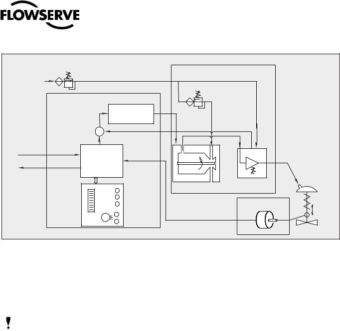
Figure 1: Logix 510si Principle of Operation
for all applications due to the close tolerances in the positioner. Optional analog feedback system as well as limit switch unit and a directly attachable double acting module complete the Logix 510si positioner accessories.
NOTE: The air supply must conform to ISA 7.0.01or IEC 770 (a dew point at least 10 ˚C / 18 ˚F below ambient temperature, particle size below five microns – one micron recommended – and oil content not to exceed one part per million).
5PRINCIPLE OF OPERATION
The Logix 510si positioner is a digital positioner with various options. The positioner consists of three main modules:
1.The microprocessor-based electronic control module includes direct local user interface switches
2.The piezo valve-based electro-pneumatic converter module
3.The infinite resolution valve position sensor.
The basic positioner operation is best understood by referring to Figure 1. The complete control circuit is powered by the two-wire, 4-20 mA command signal. The analog 4-20 mA command is passed to the microprocessor, where it is compared to the measured valve stem position. The control algorithm in the processor performs control calculations and produces an output command to the piezo valve, which drives the pneumatic amplifier. The position of the pilot valve in the pneumatic amplifier is measured and relayed to the inner loop control circuit. This two-stage control provides for more responsive and tighter control than is possible with a single stage control algorithm. The pneumatic amplifier controls the airflow to the actuator. The change of pressure and volume of the air in the actuator causes the valve to stroke. As the valve approaches the desired position, the difference between the commanded position and the measured position becomes smaller and the output to the piezo is decreased. This, in turn, causes the pilot valve to close and the resulting flow to decrease, which slows the actuator movement as it approaches the new commanded position. When the valve actuator is at the desired position, the pneumatic amplifier output is held at zero, which holds the valve in a constant position.
5
User Instructions Logix 510si - LGENIM0510-02 12/13
 ®
®
Y
Z
P$ 6LJQDO
,QWHUQDO +RXVLQJ ($57+ 7HUPLQDO
&RQQHFW 6KLHOG DW 6RXUFH *URXQG
6KLHOGHG &DEOH
P$ &XUUHQW 6RXUFH
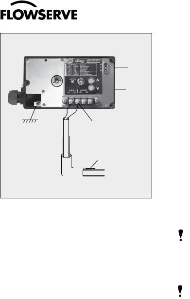
Figure 2: Wiring Diagram
6TUBING POSITIONER TO ACTUATOR
After mounting has been completed, tube the positioner to the actuator using the appropriate compression fitting connectors:
Air connections: 1/4” NPT (standard air connection)
Auxiliary power: Pressurized air or permissible gases, free of moisture and dust in according with IEC 770 or ISA 7.0.01.
Pressure range: 1,5 – 6,0 bar (22 – 87 psi)
For connecting the air piping, the following notes should be observed:
1.The positioner passageways are equipped with filters, which remove medium and coarse size dirt from the pressurized air. If necessary, they are easily accessible for cleaning.
2.Supply air should meet IEC 770 or ISA 7.0.01 requirements. A coalescing filter should be installed in front of the supply air connection Z. Now connect the air supply to the filter, which is connected to the Logix
500Series positioner.
3.With a maximum supply pressure of 6 bar (87 psi) a regulator is not required.
4. With an operating pressure of more than 6 bar (87 psi), a reducing regulator is required. The flow capacity of the regulator must be larger than the air consumption of the positioner (7 Nm3/h @ 6 bar / 4,12 scfm @ 87 psi).
5. Connect the outlet connector Y of the positioner to the actuator with tubing, independent of the action (direct or reverse).
Table 10: Connection Table
Connection |
Description |
+11 |
Input+ 4..20 mA |
-12 |
Input- 4..20 mA |
+31* |
Output+ 4..20 mA |
-32* |
Output– 4..20 mA |
|
Limit switch 1 - separate board |
|
Limit switch 2 - separate board |
Y (0 ) |
Pneumatic output signal (outlet) |
Z (0 ) |
Air supply |
* 0ptional |
|
7WIRING AND GROUNDING GUIDELINES
Electrical connections: signal cable with cable passage (NPT, or M20 x 1,5) to terminals 2 x 2,5 mm
Input signal: 4 – 20 mA
NOTE: Observe the minimum requirements of voltage and equivalent electrical load: 6,0 VDC / 300 ȍ / at 20 mA
The performance is ensured only for a minimum input current of 3,6 mA.
For wiring, the following notes should be observed:
NOTE: The input loop current signal to the Logix 510si should be in shielded cable. Shields must be tied to a ground at only one end of the cable to provide a place for environmental electrical noise to be removed from the cable. In general, shield wire should be connected at the source. (Figure 2)
Connect the 4-20 mA current source to terminals +11 and -12 (Figure 2).
Grounding Screw
The grounding screw, located inside the positioner cover, should be used to provide the unit with an adequate and reliable earth ground reference. This ground should be tied to the same ground as the electrical conduit. Additionally, the electrical conduit should be earth grounded at both ends of its run. The grounded screw must not be used to terminate signal shield wires.
Compliance Voltage (Figure 3)
Output compliance voltage refers to the voltage limit the current source can provide. A current loop system consists of the current source, wiring resistance, barrier resistance (if present), and the Logix 510si impedance.
6
 Loading...