


Installation
Operation
Maintenance
682 Seal Cooler
New generation seal cooler to meet and exceed the seal cooler requirements stated in the 4th Edition of API Standard 682
Experience In Motion
Description
The 682 Seal Cooler was designed as a new generation seal cooler to meet and exceed the seal cooler requirements stated in the First Edition of API Standard
682. These requirements address the primary specifications of the seal coolers that should be used in conjunction with mechanical seals. A secondary goal was to eliminate the fouling and corrosion problems inherent with typical seal cooler designs. With release of the Fourth Edition of API Standard 682, the requirements for this size of seal cooler are basically the same except that the cooling coil material must now be 316 instead of 304. The standard material has been upgraded to 316, allowing the 682 Seal Cooler to continue meeting the requirements of API Standard 682. The following is a brief summary of the major requirements specified for Fourth Edition “Seal Flush Coolers”:
•Seal flush coolers should not be sized for less than a 8 l / min (2 gpm) flush flow per seal.
•The seal flush fluid should be on the tube side and the cooling water on the shell side.
•When required, seal flush coolers should be designed, fabricated, and inspected according to ASME B31.3 using piping components.
•The tubes should be ¾ inch diameter with 0.095 inch minimum wall thickness.
•The tubes should be 316 austenitic stainless steel and the shell should be carbon steel.
•The seal cooler should allow complete draining and venting of both the water and process sides.
•Meets and exceeds API Standard 682 design requirements.
Design Features |
|
|
|
|
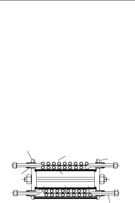
Figure 1 |
cover |
|
outer shell |
|
|
|
|
|
|
cover |
||
|
|
|
|
|
|
|
|
|
|
|
|
fitting |
inner shell |
baffle |
baffle |
baffle |
 inner cooling coil tubing
outer cooling coil tubing
|
The images of parts shown in these instructions may differ visually from the actual |
2 |
parts due to manufacturing processes that do not affect the part function or quality. |
|

•Contains 300 Series Stainless Steel for all wetted parts to provide superior corrosion resistance.
•Disassembles Easily without damaging the cooling coils for cleaning to prevent scaling and cooler fouling from reducing operating efficiencies.
•Contains Seamless Cooling Coil Tubing separated by baffles that channel the cooling water flow to prevent it from bypassing any of the cooling coils and to provide the highest efficiency.
•Allows Complete Drainage and Venting of both the tube and shell side fluids to prevent vapor lock conditions and ensure the highest efficiency.
•Can be configured for Series or Parallel Tube Flow to provide the cooling characteristics needed.
•Available with an ASME Section VIII, Division 1 “U” Stamp for applications where the equipment must be rated and verified as meeting the ASME design requirements for pressure vessels.
•Provides Explosion Resistance through a pressure relief feature that prevents the internal pressure from exceeding the allowable working pressure of the inner and outer shells.
Product Specifications
Standard Materials: |
|
|
|
• |
O-rings |
Fluoroelastomer |
|
• |
Tubing |
316 |
Stainless Steel |
• |
Fittings |
316 |
Stainless Steel |
• |
Shell and Covers |
304 |
Stainless Steel |
Technical Data: |
|
|
|
• |
Cooling Coil Tube OD |
19 mm (0.750 inch) |
|
• |
Cooling Coil Tube Wall Thickness |
2.4 mm (0.095 inch) |
|
• |
Effective Cooling Area |
0.51 m 2 (5.50 ft 2) |
|
• |
Shell (Coolant) Flow Rate |
24.6 to 75.7 l / min (6.5 to 20 gpm) |
|
• |
Tube (Product) Flow Rate |
7.6 to 37.9 l / min (2 to 10 gpm) |
|
• |
Unit Weight (Empty) |
62.1 kg (137 lbs) |
|
• |
Maximum Temperature (Tube Side) |
371°C (700°F ) |
|
• |
Maximum Temperature (Shell Side) |
93°C (200°F), Canada 65°C (200°F) |
|
• |
Max. Working Pressure (Tube Side) |
255 |
Bar @ 371°C |
|
|
(3,700 psig @ 700°F) |
|
• |
Max. Working Pressure ( Shell Side )14.5 Bar @ 93°C (210 psig @ 200°F) |
||
3
 Loading...