


USER INSTRUCTIONS
Limitorque L120-190 through L120-2000 |
Installation |
FCD LMENIM1203-00 – 10/11 |
Operation |
|
Maintenance |
|
|
Experience In Motion

Limitorque® L120-190 through L120-2000 FCD LMENIM1203-00 – 10/11
2

Limitorque® L120-190 through L120-2000 FCD LMENIM1203-00 – 10/11
Contents
1 |
Introduction |
5 |
|
|
|
|
|
|
|
1.1 Purpose |
5 |
|
|
1.2 User Safety |
5 |
|
|
||
|
2 Product Capabilities and Features |
6 |
|
|
|
||
3 Initial Inspection and Storage Instructions |
7 |
||
|
|
3.1 Product Identification |
7 |
|
|
|
|
|
|
3.2 Inspection and Recording |
8 |
|
|
|
|
|
|
3.3 Storage Procedures |
8 |
|
|
3.3.1 Short-Term Storage (less than 1 year) |
8 |
|
|
|
|
|
4 |
Actuator Weights |
10 |
|
|
|
|
5 |
Installation Instructions |
11 |
|
|
|
5.1 Safety Precautions |
11 |
|
|
|
|
|
|
5.2 Safety Practices |
12 |
|
|
|
|
|
|
5.3 Actuator Preparation |
12 |
|
|
5.3.1 Mounting Base |
13 |
|
|
|
|
|
|
5.3.2 Stem Acceptance |
13 |
|
|
|
|
|
|
5.4 Double Torque Switch |
13 |
|
|
5.4.1 Setting Torque Switch |
14 |
|
|
|
|
|
|
5.4.2 Balancing Torque Switch |
15 |
|
|
|
|
|
|
5.4.3 Torque Switch Terminal Connections |
15 |
|
|
5.5 Geared Limit Switch – Rotor Type |
16 |
|
|
|
|
|
|
5.5.1 Setting Limit Switch |
16 |
|
|
|
|
|
|
5.5.2 Combination of Contacts |
19 |
|
|
5.6 Position Indication |
19 |
|
|
|
|
|
|
5.6.1 Local Position Indication |
19 |
|
|
|
|
|
|
5.6.2 Remote Position Indication |
20 |
|
|
5.6.3 Calibrating Position Transmitter PT20SD |
20 |
|
|
|
|
|
6 |
Operation |
21 |
|
|
|
|
|
|
6.1 Electrical Start-Up |
21 |
|
|
6.1.1 Typical Wiring Diagram |
22 |
|
|
|
|
|
|
6.2 Manual Operation |
22 |
|
|
|
|
|
|
6.3 Motor Operation |
23 |
|
|
6.4 Torque and Travel Limiting |
23 |
|
|
|
|
|
7 |
Maintenance |
24 |
|
|
|
|
|
|
7.1 Lubrication |
24 |
|
|
7.1.1 Lubrication Inspection |
24 |
|
|
|
|
|
|
7.1.2 Factory Lubricant |
25 |
|
|
|
|
|
8 |
Disassembly and Reassembly |
26 |
|
|
8.1 L120-190, -420, and -800 |
26 |
|
|
|
|
|
|
8.1.1 To Replace Stem Nut Only |
26 |
|
|
|
|
|
|
8.1.2 L120-190, 420, 800 Disassembly |
27 |
|
|
8.1.3 Reassembling Actuator Sizes L120-190, -420 and -800 |
28 |
|
|
|
|
|
|
8.1.4 Gaskets |
29 |
|
|
|
|
|
|
8.2 L120-2000 |
38 |
|
|
8.2.1 Drive 2 Disassembly (Thrust Housing Only) |
38 |
|
|
|
|
|
|
8.2.2 Drive 1 Disassembly (Torque Housing) |
38 |
|
|
|
|
|
|
8.2.3 Drive 1 (Torque Housing) Reassembly |
40 |
|
|
8.2.4 Drive 2 (Thrust Housing Only) Reassembly |
42 |
|
|
|
|
3
flowserve.com

Limitorque® L120-190 through L120-2000 FCD LMENIM1203-00 – 10/11
9 |
Standard Wiring Diagrams |
49 |
|
|
|
10 |
Troubleshooting |
52 |
|
|
|
11 |
How to Order Parts |
53 |
12 |
Regulatory Information |
54 |
|
|
|
Figures
Figure 3.1 – L120-190 through 2000 |
8 |
|
|
Figure 5.1 – Double Torque Switch |
13 |
|
|
Figure 5.2 – Setting Torque Switch |
14 |
|
|
Figure 5.3 – Ring Tongue Terminal |
15 |
|
|
Figure 5.4 – Geared Limit Switch |
17 |
|
|
Figure 5.5 – Setting Geared Limit Switch |
18 |
|
|
Figure 5.6 – Position Indicators |
19 |
|
|
Figure 5.7 – Typical Connection for a 1000 ohm Potentiometer |
20 |
|
|
Figure 8.1 – L120-190 and -420 Drive Sleeve Side View (Refer to Table 8.1 for parts list) |
30 |
|
|
Figure 8.2 – L120-190 and -420 Worm Shaft Side View (Refer to Table 8.1 for parts list) |
31 |
|
|
Figure 8.3 – L120-190 and -420 Top View (Refer to Table 8.1 for parts list) |
32 |
|
|
Figure 8.4 – L120-800 Drive Sleeve Side View (Refer to Table 8.1 for parts list) |
33 |
|
|
Figure 8.5 – L120-800 Worm Shaft Side View (Refer to Table 8.1 for parts list) |
34 |
|
|
Figure 8.6 – L120-800 Top View (Refer to Table 8.1 for parts list) |
35 |
|
|
Figure 8.7 – L120-2000 Drive Sleeve Side View (Torque Base) (Refer to Table 8.2 for parts list) |
43 |
|
|
Figure 8.8 – L120-2000 Top View (Refer to Table 8.2 for parts list) |
44 |
|
|
Figure 8.9 – L120-2000 Side View (Refer to Table 8.2 for parts list) |
45 |
|
|
Figure 8.10 – L120-2000 Exploded View |
46 |
|
|
Figure 9.1 – Wiring Diagram – No Controls |
49 |
|
|
Figure 9.2 – Wiring Diagram – Integral Controls |
50 |
|
|
Figure 9.3 – Wiring Diagram – NCU |
51 |
|
|
Tables
Table 4.1 – Actuator Weights |
10 |
|
|
|
|
Table 5.1 – Mounting Base Dimensions |
13 |
|
|
|
|
Table 5.2 – Maximum Stem Acceptance |
13 |
|
|
|
|
Table 5.3 – Terminal Dimensions By Cable Size |
16 |
|
|
|
|
Table 5.4 |
– Maximum Drive Sleeve Turns |
17 |
|
|
|
Table 7.1 |
– Lubricant Weights |
25 |
|
|
|
Table 8.1 |
– L120-190, -420 and -800 typical parts list |
36 |
|
|
|
Table 8.2 |
– L120-2000 typical parts list |
47 |
|
|
|
4

Limitorque® L120-190 through L120-2000 FCD LMENIM1203-00 – 10/11
1 Introduction
1.1 Purpose
This Installation and Maintenance Manual explains how to install and maintain L120-190 through -2000 actuators. Information on installation, disassembly, reassembly, lubrication, and parts is provided.
1.2 User Safety
Safety notices in this manual detail precautions the user must take to reduce the risk of personal injury and damage to the equipment. The user must read and be familiar with these instructions before attempting installation, operation, or maintenance. Failure to observe these precautions could result in serious bodily injury, damage to the equipment, warranty void, or operational difficulty.
Safety notices are presented in this manual in three forms:
cc WARNING: Refers to personal safety. Alerts the user to potential danger. Failure to follow warning notices could result in personal injury or death.
aa CAUTION: Directs the user’s attention to general precautions that, if not followed, could result in personal injury and/or equipment damage.
NOTE: Highlights information critical to the user’s understanding of the actuator’s installation and operation.
5
flowserve.com

Limitorque® L120-190 through L120-2000 FCD LMENIM1203-00 – 10/11
2 Product Capabilities and Features
L120 Series actuators operate without modification in any rising or non-rising stem application for linear-action valves.
The actuators meet rigid safety requirements and are available in weatherproof, explosionproof, and submersible configurations.
The actuators are compatible with a wide range of control options from stand-alone actuators with local control stations to open standards-based DDC-100 networks with up to 250 actuators.
The actuators are designed with integral control packages including plug-in interconnect boards that increase control functionality for stand-alone or networked actuators.
Torque overload protection is provided in both directions of travel.
6

Limitorque® L120-190 through L120-2000 FCD LMENIM1203-00 – 10/11
3 Initial Inspection
and Storage Instructions
cc WARNING: Read this Installation and Maintenance Manual carefully and completely before attempting to store the actuator. Be aware of the electrical hazards.
3.1 Product Identification
The actuator nameplate is located on the back of the actuator opposite the limit switch controls compartment. The nameplate contains the following information:
• Limitorque name |
• Order number |
||
• |
Point of manufacture |
• |
Serial number |
• |
Actuator size |
• |
Customer tagging |
The motor nameplate is located on the motor. The nameplate contains the following information:
• ID number |
• Enclosure type |
||
• |
Run torque |
• |
Volts |
• RPM |
• Locked rotor amps |
||
• |
Full load amps |
• |
Duty |
• |
Insulation class |
• |
Horsepower |
• |
Space heater size |
• |
Phase |
• |
Service Factor |
• |
Motor code |
• Cycles |
• Connection diagram |
||
•Ambient temperature
•Start torque
7
flowserve.com
Limitorque® L120-190 through L120-2000 FCD LMENIM1203-00 – 10/11
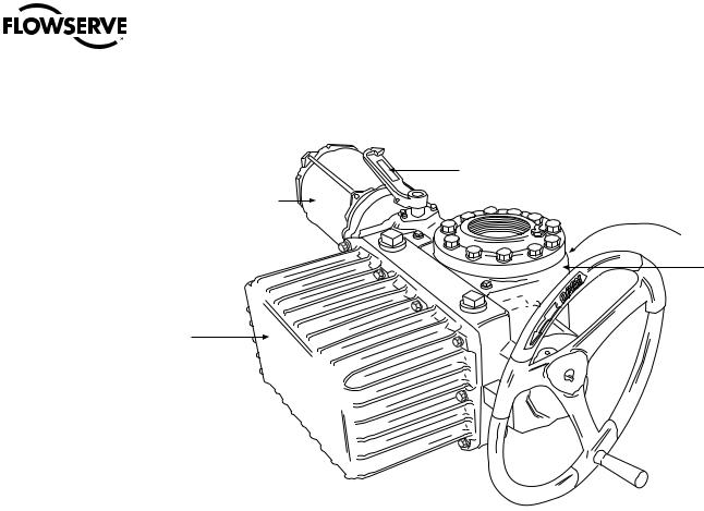
Figure 3.1 – L120-190 through 2000
Declutch
Lever
Motor
Actuator Nameplate (hidden)
Housing
 Handwheel
Limit Switch
and Controls
Compartment
3.2 Inspection and Recording
Upon receipt of the actuator, inspect the condition of the equipment and record nameplate information.
1.Carefully remove actuator from shipping carton or skid. Thoroughly examine the equipment for any physical damage that may have occurred during shipment. If damaged, immediately report the damage to the transport company.
2.Record the actuator nameplate information for future reference, i.e., ordering parts, obtaining further information.
3.3 Storage Procedures
NOTE: The following are our recommended storage procedures to retain maximum product integrity during short-term storage. Failure to comply with recommended procedures will void the warranty. For longer-term storage, contact Limitorque for procedures and recommendations.
3.3.1 Short-Term Storage (less than 1 year)
Actuators are not weatherproof until properly installed on the valve or prepared for storage.
Store actuators in a clean, dry, protected warehouse away from excessive vibration and rapid tempera- 8 ture changes. If the actuators must be stored outside, they must be stored off the ground, high enough
to prevent them from being immersed in water or buried by snow.

Limitorque® L120-190 through L120-2000 FCD LMENIM1203-00 – 10/11
1.Position the actuator in storage with motor and switch compartment horizontal.
2.Connect the space heaters (if supplied) or place desiccant in the switch compartment.
3.Connect space heaters if actuator is to be stored in a damp place.
4.Replace all plastic caps or plugs with pipe plugs and ensure that all covers are tight.
5.If the actuator is mounted on a valve and the stem protrudes from the actuator, a suitable stem cover must be provided.
9
flowserve.com

Limitorque® L120-190 through L120-2000 FCD LMENIM1203-00 – 10/11
4 Actuator Weights
The approximate L120 actuator weights are provided below:
Table 4.1 – Actuator Weights
Actuator Size |
Control Types |
Drive 1 Weight Side HW |
Drive 2 Weight Side HW |
|||
lb. |
kg |
lb. |
kg |
|||
|
|
|||||
|
NCU3 |
520 |
192 |
520 |
192 |
|
L120-190 |
BIC3 |
586 |
217 |
586 |
217 |
|
|
UEC/Clamshell3 |
586 |
217 |
586 |
217 |
|
|
NCU3 |
1065 |
394 |
1065 |
394 |
|
L120-420 |
BIC3 |
1130 |
418 |
1130 |
418 |
|
|
UEC/Clamshell3 |
1220 |
451 |
1220 |
451 |
|
L120-800 |
NCU3 |
12701 |
4711 |
17002 |
6292 |
|
L120-2000 |
NCU3 |
25001 |
9251 |
33002 |
12212 |
|
Note 1: Torque Only
Note 2: Torque and Thrust
Note 3: NCU = No Controls Actuator
BIC = Basic Integral Controls
UEC = Universal Electronic Controller
10
Limitorque® L120-190 through L120-2000 FCD LMENIM1203-00 – 10/11
5 Installation Instructions
5.1 Safety Precautions
cc WARNING: Read this Installation and Maintenance Manual carefully and completely before
attempting to install, operate, or troubleshoot the Limitorque actuator. |
|
cc WARNING: Be aware of electrical hazards. Turn off incoming power before working on the |
|
actuator and before opening the switch compartment. |
|
cc WARNING: Potential HIGH PRESSURE vessel — be aware of high-pressure hazards associated |
|
with the attached valve or other actuated device when installing or performing maintenance |
|
on the actuator. Do not remove the actuator mounting bolts from the valve or actuated device |
|
unless the valve or device stem is secured or there is no pressure in the line. |
|
cc WARNING: For maintenance and/or disassembly of the actuator while installed on the valve, |
|
ensure that the actuator is not under thrust or torque load. If the valve must be left in service, |
|
the valve stem must be locked in such a way as to prevent any movement of the valve stem. |
|
cc WARNING: Do not attempt to remove the spring cartridge cap, housing cover, or stem nut |
|
locknut from the actuator while the valve or actuated device is under load. |
|
cc WARNING: Do not manually operate the actuator with devices other than the installed hand- |
|
wheel and declutch lever. Using force beyond the ratings of the actuator and/or using additive |
|
force devices such as cheater bars, wheel wrenches, pipe wrenches, or other devices on the |
|
actuator handwheel or declutch lever may cause serious personal injury and/or damage to the |
|
actuator and valve. |
|
cc WARNING: Do not exceed any design limitations or make modifications to this equipment |
11 |
without first consulting Limitorque. |
|
flowserve.com

Limitorque® L120-190 through L120-2000 FCD LMENIM1203-00 – 10/11
cc WARNING: Actuators equipped with electrical devices (motors, controls) requiring field wiring must be wired and checked for proper operation by a qualified tradesman.
cc WARNING: Use of the product must be suspended any time it fails to operate properly.
aa CAUTION: Do not use oversized motor overload heaters. Instead, look for the cause of the overload.
aa CAUTION: Do not operate the valve under motor operation without first setting or checking the limit switch setting and motor direction.
aa CAUTION: Do not force the declutch lever into the motor operation position. The lever returns to this position automatically when the motor is energized.
aa CAUTION: Do not depress the declutch lever during motor operation to stop valve travel.
aa CAUTION: Do not use replacement parts that are not genuine Flowserve Limitorque parts, as serious personal injury and/or damage to the actuator and valve may result.
aa CAUTION: Do not lift actuator/gearbox or actuator/valve combinations with only the eye bolts in the L120 actuator. These eye bolts are designed for lifting the L120 actuator only.
aa CAUTION: Do not lift the actuator by handwheel.
5.2 Safety Practices
The following check points should be performed to maintain safe operation of the L120 actuator:
• Eye bolts are designed for lifting only the actuator and not associated gearboxes or valves.
• Mount motor on a horizontal plane, if possible. Preferably, keep the motor or limit switch compartment from hanging down. This prevents head of grease from being against motor or switch seals.
• Keep the switch compartment clean and dry.
• Keep the valve stem clean and lubricated.
• Set up periodic operating schedules for infrequently used valves.
• Verify that all actuator wiring is in accordance with the applicable wiring diagram.
• Carefully check for correct motor rotation direction. If the motor is driving the valve in the wrong direction, interchange any two leads on the three-phase motor or switch the armature leads on DC motors.
• Use a protective stem cover. Check valve stem travel and clearance before mounting covers on rising stem valves.
• Verify that a locking nut tightly secures the stem nut and that the top thread of the lock nut is crimped and staked in two places.
• For the DC motor, keep the armature clean and periodically check brushes for proper contact and wear.
12 |
5.3 Actuator Preparation |
|
|
|
Note: Replace all molded plastic conduit and top protectors (installed for shipping purposes only) with |
|
pipe plugs when installation wiring is complete. |
Limitorque® L120-190 through L120-2000 FCD LMENIM1203-00 – 10/11
5.3.1 Mounting Base
The mounting hole sizes and quantities are as detailed in Table 5.1, below:
Table 5.1 – Mounting Base Dimensions
Actuator Size |
Mounting Holes |
Tap Size |
|
ISO |
|
Bolt Circle |
|
ISO |
Quantity |
MSS |
|
|
MSS |
|
|||
|
|
|
|
|
|
|||
L120-190 |
|
3/4–10 x 1.13 |
|
M20 x 2.5 x 32 |
|
11.75 |
|
298 mm |
8 |
|
|
|
|||||
L120-420 |
8 |
7⁄8–9 x 1.75 |
|
N/A |
|
14.0 |
|
N/A |
L120-800 (Torque Only) |
8 |
3/4–10 x 1.63 |
|
N/A |
|
17.0 |
|
N/A |
L120-800 (Thrust Only) |
8 |
1.25–7 x 2.0 |
|
N/A |
|
16 |
|
N/A |
|
|
|
|
|
|
|
|
|
L120-2000 (Torque Only) |
16 |
1–8 x 2.0 |
|
N/A |
|
23.5 |
|
N/A |
|
|
|
|
|
|
|
|
|
L120-2000 (Thrust Only) |
12 |
1-1/2–6 x 3.0 |
|
N/A |
|
18.0 |
|
N/A |
|
|
|
|
|
|
|
|
|
5.3.2 Stem Acceptance
The maximum stem acceptance is provided in Table 5.2, below:
Table 5.2 – Maximum Stem Acceptance
Actuator size |
Drive 2 Tapped |
|
Drive 1 Bore |
|
Drive 1 Key |
|||||
inch |
mm |
|
inch |
|
mm |
|
inch |
|
mm |
|
|
|
|
|
|
||||||
L120-190 |
|
89 |
|
2.875 |
|
73 |
|
3/4 x 1/4 |
|
20 x 12 |
3.5 |
|
|
|
|
||||||
|
|
|
|
|
|
|
|
|
|
|
L120-420 |
5 |
127 |
|
4.25 |
|
108 |
|
1 x 3/4 |
|
28 x 16 |
|
|
|
|
|
|
|
|
|
|
|
L120-800 |
5 |
127 |
|
7 |
|
178 |
|
1 x 3/4 |
|
32 x 18 |
|
|
|
|
|
|
|
|
|
|
|
L120-2000 |
6.25 |
159 |
|
8.00 |
|
203 |
|
11/4 x 7⁄8 |
|
40 x 22 |
NOTE: For complete mounting dimensions, see sales brochure LMENBR1200.
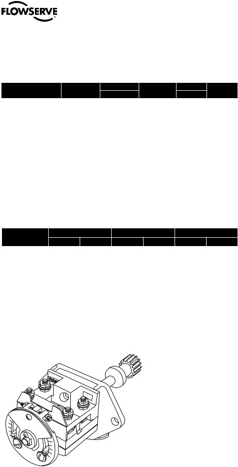
5.4 Double Torque Switch
The torque switch is designed to protect the actuator in open and close directions.
Figure 5.1 – Double Torque Switch
OPEN
13
Note: See Caution and Note on following page.
flowserve.com

Limitorque® L120-190 through L120-2000 FCD LMENIM1203-00 – 10/11
aa CAUTION: Disconnect all incoming power before opening limit switch compartment or working on the torque switch.
•Do not use abrasive cloth to clean the contacts on the torque switch.
•Do not torque-seat 90° operation valves or run them against the stops. This may cause damage to the valve.
NOTE: If the actuator has “torqued out,” release torque buildup by operating the actuator manually in opposite direction 1/2 to 1 turn of the output drive sleeve.
NOTE: Torque switch contacts are rated 600 volts, in accordance with NEMA ICS-2.
5.4.1 Setting Torque Switch
The torque switch was set at the factory according to customer-supplied information regarding necessary torque or thrust output provided at the time of the order. However, if the torque switch is newly installed or the setting needs to be adjusted, follow the procedure below:
aa CAUTION: A maximum stop setting plate is provided on most actuators. Do not remove this plate. Do not exceed the setting indicated by this plate without contacting Limitorque.
•Installing or adjusting the torque switch with the operator in a “loaded” condition will result in a loss of torque protection.
Item letters correspond to Figure 5.2.
1.Place the L120 actuator in manual mode.
2.Release the load on the wormshaft spring pack. Put operator in manual mode and operate in opposite direction until switch is in neutral position.
3.For open and close directions, loosen Screw (A) and move Pointer (B) to desired position. A higher number indicates a high torque and/or thrust output.
4.Tighten Screw (A).
5.Operate the valve electrically to seat the valve and to ensure tight shutoff.
Figure 5.2 – Setting Torque Switch
Maximum Stop
Setting Plate
B
14
Torque Switch Dial
A
Limitorque® L120-190 through L120-2000 FCD LMENIM1203-00 – 10/11
5.4.2 Balancing Torque Switch
Item letters correspond to Figure 5.2.
1.Place the actuator in manual mode.
2.Remove the load from the wormshaft spring pack.
NOTE: If the actuator has “torqued out,” release torque buildup by operating the actuator manually in opposite direction 1/2 to 1 turn.
3.Note the open and close torque switch settings prior to re-installing the torque switch.
4.Loosen Screws (A) and position both Pointers (B) at the #1 setting; tighten Screws (A).
5.Mount the torque switch and tighten the mounting screws. Verify that both contact pointers are touching the arms. The interface between the pointers and the arm is found beneath the torque switch dial. If the pointers and the arms are not in contact, the clearance on the open and close torque switches should be equal. If not equal, the torque switch needs to be balanced. (See Step 7.)
6.If the pointers and arms are in contact on both sides of the switch, manually rotate the torque switch dial clockwise and counter-clockwise to determine if there is equal backlash in both directions of rotation. If there is not equal backlash in both directions, the torque switch needs to be balanced. (See Step 7.)
7.Loosen both hex nuts.
8.Back out one setscrew and tighten the other setscrew until there is equal backlash in both directions of rotation of the dial, or equal clearance between the pointers and arms.
9.Tighten the hex nuts and return the torque switch to its original settings.
aa CAUTION: The balancing screws should not be touched except during the balancing procedure.
The switch is now balanced and ready for the pointers to be returned to their original settings.
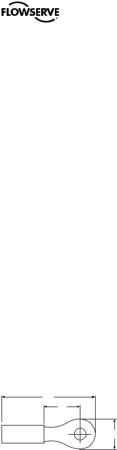
5.4.3 Torque Switch Terminal Connections
Wiring connections to the L120 geared limit switch, torque switch, and marathon terminal strips are to be made using ring-tongue terminals as shown below:
Figure 5.3 – Ring Tongue Terminal
A
C
B
See Table 5.3, next page |
15 |
flowserve.com

Limitorque® L120-190 through L120-2000 FCD LMENIM1203-00 – 10/11
Table 5.3 – Terminal Dimensions By Cable Size
AWG |
Screw Hole |
Insulation |
|
Thomas & |
|
A |
|
B |
|
C |
|
Betts P/N |
|
|
|
||||||
|
|
|
|
|
|
|
|
|
|
|
22-16 |
|
Vinyl |
|
18RA-10 |
|
.97 |
|
.31 |
|
.27 |
#10 |
|
|
|
|
||||||
|
|
|
|
|
|
|
|
|
|
|
18-14 |
#10 |
Vinyl |
|
14RB-10 |
|
.97 |
|
.31 |
|
.27 |
|
|
|
|
|
|
|
|
|
|
|
12-10 |
#10 |
Vinyl |
|
14RC-10 |
|
1.06 |
|
.31 |
|
.27 |
|
|
|
|
|
|
|
|
|
|
|
Terminals are to be crimped using Thomas & Betts crimping tool WT111M.
5.5 Geared Limit Switch – Rotor Type
aa CAUTION: The geared limit switch is not preset at the factory and must be adjusted after the actuator has been mounted on associated equipment.
Note: Limit switch contacts are rated 600 volts, in accordance with NEMA ICS-2
•Disconnect all incoming power to the actuator prior to opening the limit switch compartment and adjusting the switch.
•Consult the relevant wiring diagram for limit switch contact development. All L120 actuators are supplied with 16-contact limit switches - four switches on each of the four rotors. Two rotors are used for end-of-travel indication. The remaining two rotors may be adjusted for any intermediate point-of-travel.
•Do not use abrasive cloth to clean the contacts on the limit switch.
•Do not attempt to repair gearing in the limit switch. Replace entire gear frame assembly if necessary.
5.5.1 Setting Limit Switch
The maximum number of drive sleeve turns available is a funtion of actuator size, worm gear ratio, and type of switch. See Table 5.4. The Intermediate Shaft shown in Figure 5.5 may take a considerable number of turns before rotor trip occurs.
cc WARNING: Potential Explosion Hazard. Do not use a variable speed electric drill for setting the limit switch in an explosive environment.
aa CAUTION: When setting the limit switch rotor segments (cams) using a variable speed electric drill, do not run drill at speeds higher than 200 RPM. Operating the drill at high speeds can damage the gearing within the limit switch.
16
Limitorque® L120-190 through L120-2000 FCD LMENIM1203-00 – 10/11
Table 5.4 – Maximum Drive Sleeve Turns
|
Limit Switch Gearing |
|
|
|
PIC Gearing |
|||
Actuator Size |
W.G. Ratio |
4-Gear |
|
5-Gear |
|
PIC or R/I (270) |
|
RVDT(90) |
L120-190 |
|
3110 |
|
31100 |
|
13706 |
|
4569 |
13.3:1 |
|
|
|
|||||
|
|
|
|
|
|
|
|
|
|
33:1 |
1250 |
|
12500 |
|
5521 |
|
1837 |
|
|
|
|
|
|
|
|
|
|
60:1 |
690 |
|
6900 |
|
3037 |
|
1012 |
|
|
|
|
|
|
|
|
|
|
85:1 |
N/A |
|
N/A |
|
N/A |
|
N/A |
|
|
|
|
|
|
|
|
|
L120-420 |
10.33:1 |
N/A |
|
N/A |
|
N/A |
|
N/A |
|
|
|
|
|
|
|
|
|
|
16:1 |
3300 |
|
33000 |
|
11405 |
|
3797 |
|
|
|
|
|
|
|
|
|
|
41:1 |
1280 |
|
12800 |
|
4445 |
|
1481 |
|
|
|
|
|
|
|
|
|
|
57:1 |
910 |
|
9100 |
|
3195 |
|
1065 |
|
|
|
|
|
|
|
|
|
|
80:1 |
N/A |
|
N/A |
|
N/A |
|
N/A |
|
|
|
|
|
|
|
|
|
L120-800 |
12.67:1 |
N/A |
|
N/A |
|
N/A |
|
N/A |
|
|
|
|
|
|
|
|
|
|
19:1 |
2850 |
|
28500 |
|
9586 |
|
3195 |
|
|
|
|
|
|
|
|
|
|
49:1 |
1050 |
|
10500 |
|
3720 |
|
1240 |
|
|
|
|
|
|
|
|
|
|
58:1 |
N/A |
|
N/A |
|
N/A |
|
N/A |
|
|
|
|
|
|
|
|
|
|
86:1 |
N/A |
|
N/A |
|
N/A |
|
N/A |
|
|
|
|
|
|
|
|
|
L120-2000 |
43:1 |
1210 |
|
12100 |
|
4234 |
|
1413 |
|
|
|
|
|
|
|
|
|
|
71:1 |
740 |
|
7400 |
|
2566 |
|
855 |
|
|
|
|
|
|
|
|
|
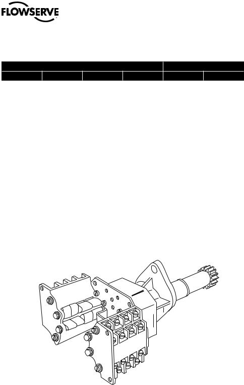
Figure 5.4 – Geared Limit Switch
Set the limit switch as shown on the following page. All item letters and piece numbers refer to Figure 5.5.
17
flowserve.com
 Loading...