


 Loading...
Logix ® 500+ Series
Digital Positioner
FCD LGENIM0105-10 11/13
USER INSTRUCTIONS
Installation
Operation
Maintenance
Safety Manual

User Instructions - Logix® 500+ Series Digital Positioners FCD LGENIM0105-10 11/13
Quick Start
Instructions
Page 26
flowserve.com |
2 |

User Instructions - Logix® 500+ Series Digital Positioners FCD LGENIM0105-10 11/13
CONTENTS |
|
|
1.1 |
USING THIS DOCUMENT............................................................ |
4 |
1.2 |
TERMS CONCERNING SAFETY ...................................................... |
4 |
1.3 |
PROTECTIVE CLOTHING ............................................................. |
4 |
1.4 |
QUALIFIED PERSONNEL ............................................................. |
4 |
1.5 |
VALVE AND ACTUATOR VARIATIONS............................................. |
4 |
1.6 |
SPARE PARTS ......................................................................... |
4 |
1.7 |
SERVICE / REPAIR.................................................................... |
4 |
1.8 |
BASIC OPERATION ................................................................... |
5 |
1.9 |
HART.................................................................................. |
5 |
1.10 |
POSITION DEFINITION............................................................... |
5 |
1.11 |
COMMAND INPUT AND FINAL COMMAND...................................... |
5 |
1.12 |
OUTER LOOP.......................................................................... |
5 |
1.13 |
INNER LOOP........................................................................... |
6 |
1.14 |
DETAILED SEQUENCE OF POSITIONER OPERATIONS ........................... |
6 |
1.15 |
INNER LOOP OFFSET................................................................. |
6 |
2 |
SPECIFICATIONS............................................... |
8 |
2.1 |
INPUT SIGNAL ........................................................................ |
8 |
2.2 |
AIR SUPPLY ........................................................................... |
8 |
2.3 |
PNEUMATIC OUTPUT................................................................ |
8 |
2.4 |
STROKE OUTPUT ..................................................................... |
8 |
2.5 |
ANALOG OUTPUT – MULTI-FUNCTION CARD.................................. |
8 |
2.6 |
REMOTE MOUNT SPECIFICATIONS................................................ |
8 |
2.7 |
LIMIT SWITCH SPECIFICATIONS.................................................... |
9 |
2.8 |
POSITIONER PERFORMANCE CHARACTERISTICS ................................ |
9 |
2.9 |
PHYSICAL SPECIFICATIONS.......................................................... |
9 |
2.10 |
TEMPERATURE........................................................................ |
9 |
2.11 |
VALVESIGHT DTM SOFTWARE SPECIFICATIONS............................... |
9 |
3 |
HAZARDOUS AREA CERTIFICATIONS.......... |
10 |
4 |
STORAGE AND UNPACKING.......................... |
11 |
4.1 |
STORAGE ............................................................................ |
11 |
4.2 |
UNPACKING ......................................................................... |
11 |
4.3 |
PRE-INSTALLATION INSPECTION ................................................. |
11 |
5 |
MOUNTING AND INSTALLATION ................... |
12 |
5.1 |
MOUNTING TO MARK ONE LINEAR VALVES ................................. |
12 |
5.2 |
MOUNTING TO FLOWTOP LINEAR VALVES ................................... |
13 |
5.3 |
MOUNTING TO STANDARD VALTEK ROTARY VALVES....................... |
15 |
5.4 |
MOUNTING TO MAXFLO ROTARY VALVES ................................... |
17 |
5.5 |
MOUNTING TO ROTARY NAMUR (AUTOMAX) VALVES ................. |
18 |
5.6 |
MOUNTING TO A LINEAR NAMUR PNEUMATIC ACTUATOR ............. |
19 |
6 |
TUBING ............................................................. |
20 |
6.1 |
DETERMINE AIR ACTION ......................................................... |
20 |
6.2 |
CONNECT SUPPLY PORT .......................................................... |
20 |
6.3 |
PURGING SINGLE ACTING ACTUATORS ........................................ |
20 |
6.4 |
VENTED DESIGN.................................................................... |
21 |
7 |
ELECTRICAL CONNECTIONS......................... |
22 |
7.1 |
ELECTRICAL TERMINALS........................................................... |
22 |
7.2 |
COMMAND INPUT (4-20 MA) CONNECTION ................................ |
22 |
7.3 |
MULTI-FUNCTION CARD (AO, DO, DI) ...................................... |
24 |
7.4 |
LIMIT SWITCHES.................................................................... |
25 |
7.5 |
REMOTE MOUNT .................................................................. |
25 |
7.6 |
CONNECTIONS FOR INTRINSICALLY SAFE OPERATION ....................... |
25 |
8 |
STARTUP .......................................................... |
26 |
8.1 |
QUICK START INSTRUCTIONS .................................................... |
26 |
8.2 |
LOCAL USER INTERFACE OVERVIEW ............................................ |
26 |
8.3 |
CONFIGURATION SWITCH SETTINGS (505+) ................................. |
27 |
8.4 |
CONFIGURATION SWITCH SETTINGS (510+ AND 520MD+) ............. |
27 |
8.5 |
STROKE CALIBRATION ............................................................. |
28 |
8.6 |
ANALOG OUTPUT (AO) CALIBRATION ........................................ |
29 |
9 |
POSITIONER FUNCTIONS (NO DISPLAY |
|
|
REQUIRED) ....................................................... |
30 |
9.1 |
LIVE MANUAL TUNING (ADJUSTING THE GAIN) ............................. |
30 |
9.2 |
LOCAL CONTROL OF VALVE POSITION ......................................... |
30 |
9.3 |
COMMAND SOURCE RESET ...................................................... |
30 |
9.4 |
FACTORY RESET .................................................................... |
30 |
9.5 |
VIEWING VERSION NUMBERS ................................................... |
30 |
10 POSITIONER FUNCTIONS (LCD DISPLAY).... |
31 |
|
10.1 |
MAIN DISPLAY VIEW.............................................................. |
31 |
10.2 |
MENU OVERVIEW ................................................................. |
33 |
10.3 |
MENU FEATURES .................................................................. |
34 |
11 |
HART COMMUNICATION ................................. |
39 |
11.1 |
VALVESIGHT DTM ................................................................ |
39 |
11.2 |
HART 375/475 HANDHELD COMMUNICATOR ............................ |
39 |
11.3 |
CHANGING HART VERSIONS.................................................... |
39 |
11.4 |
BURST MODE....................................................................... |
39 |
12 |
MODEL FEATURES .......................................... |
40 |
12.1 |
LOGIX 505+ ........................................................................ |
40 |
12.2 |
LOGIX 510+ ........................................................................ |
40 |
12.3 |
LOGIX 520MD+................................................................... |
40 |
12.4 |
MD+ POSITIONER DIAGNOSTIC LEVELS ....................................... |
40 |
12.5 |
VALVESIGHT DTM DIAGNOSTIC LEVELS....................................... |
40 |
13 |
MULTI-FUNCTION CARD ................................. |
41 |
13.1 |
ANALOG OUTPUT (AO) .......................................................... |
41 |
13.2 |
DISCRETE OUTPUT (DO) ......................................................... |
41 |
13.3 |
DISCRETE INPUT (DI) ............................................................. |
41 |
14 |
LIMIT SWITCHES .............................................. |
42 |
14.1 |
LIMIT SWITCH PRINCIPLES OF OPERATION .................................... |
42 |
14.2 |
LIMIT SWITCH TYPES .............................................................. |
42 |
15 |
REMOTE MOUNT .............................................. |
42 |
15.1 |
REMOTE MOUNT OPEREATION ................................................. |
42 |
16 REQUIREMENTS FOR SAFETY INTEGRITY .. |
43 |
|
16.1 |
FAIL SAFE STATE ................................................................... |
43 |
16.2 |
SAFETY FUNCTION ................................................................. |
43 |
16.3 |
FAIL SAFE STATE RESPONSE TIME .............................................. |
43 |
16.4 |
POSITIONER MODEL SELECTION AND SPECIFICATION ....................... |
43 |
16.5 |
INSTALLATION ...................................................................... |
43 |
16.6 |
REQUIRED CONFIGURATION SETTINGS......................................... |
43 |
16.7 |
MAXIMUM ACHIEVABLE SIL..................................................... |
43 |
16.8 |
RELIABILITY DATA .................................................................. |
43 |
16.9 |
LIFETIME LIMITS .................................................................... |
43 |
16.10 |
PROOF TESTING .................................................................... |
43 |
16.11 |
MAINTENANCE ..................................................................... |
44 |
16.12 |
REPAIR AND REPLACEMENT ...................................................... |
44 |
16.13 |
TRAINING REQUIREMENTS ....................................................... |
44 |
17 |
MAINTENANCE AND REPAIR ......................... |
45 |
17.1 |
SCHEDULED MAINTENANCE...................................................... |
45 |
17.2 |
REQUIRED TOOLS AND EQUIPMENT ............................................ |
45 |
17.3 |
TORQUE SPECIFICATION FOR SCREWS.......................................... |
45 |
17.4 |
INSTALLING A LIMIT SWITCH ..................................................... |
45 |
17.5 |
REPLACING THE LCD BOARD .................................................... |
46 |
17.6 |
REPLACING AN AUXILIARY CARD................................................ |
46 |
17.7 |
REPLACING A MAIN BOARD ..................................................... |
47 |
17.8 |
REPLACING THE PRESSURE SENSOR BOARD................................... |
47 |
17.9 |
CLEANING AND REPLACING A DOUBLE ACTING PILOT RELAY ............. |
48 |
17.10 |
REPLACING A SINGLE ACTING PILOT RELAY................................... |
49 |
18 |
TROUBLESHOOTING....................................... |
50 |
18.1 |
TROUBLESHOOTING GUIDE ...................................................... |
50 |
18.2 |
STATUS CODE INDEX .............................................................. |
51 |
18.3 |
STATUS CODE DESCRIPTIONS .................................................... |
52 |
18.4 |
HELP FROM FLOWSERVE ......................................................... |
59 |
19 |
POSITIONER DIMENSIONS.............................. |
60 |
19.1 |
POSITIONER DIMENSIONS........................................................ |
60 |
20 |
HOW TO ORDER............................................... |
61 |
20.1 |
POSITIONERS........................................................................ |
61 |
20.2 |
SPARE PARTS KITS ................................................................. |
62 |
20.3 |
GAGE BLOCK........................................................................ |
62 |
20.4 |
VDI/VDE 3847 MOUNTING BLOCKS ........................................ |
62 |
20.5 |
MOUNTING KITS ................................................................... |
62 |
INDEX........................................................................... |
62 |
|
flowserve.com |
3 |

User Instructions - Logix® 500+ Series Digital Positioners FCD LGENIM0105-10 11/13
GENERAL INFORMATION
1.1Using This Document
Product users and maintenance personnel should thoroughly review this manual prior to installing, operating, or performing any maintenance on the positioner.
The following instructions are designed to assist in unpacking, installing and performing maintenance as required on Logix® 500MD+ positioners. Series 500 is the term used for all the positioners herein; however, specific numbers indicate features specific to model (i.e., Logix 520 indicates that the positioner has HART® protocol). See Logix 500MD+ Model Number table in this manual for a breakdown of specific model numbers.
Separate Flow Control Products User Instructions cover the valve, actuator, or portions of the system and other accessories. Refer to the appropriate instructions when this information is needed. In most cases FLOWSERVE valves, actuators and accessories are designed for specific applications with regard to medium, pressure and temperature. For this reason they should not be used in other applications without first contacting the manufacturer.
To avoid possible injury to personnel or damage to positioner parts, DANGER and CAUTION notes must be strictly followed.
1.2Terms Concerning Safety
The safety terms DANGER, CAUTION and NOTE are used in these instructions to highlight particular dangers and/or to provide additional information on aspects that may not be readily apparent.
NOTE: Indicates and provides additional technical information, which may not be very obvious even to qualified personnel.
 CAUTION: Indicates that minor personal injury and/or property damage can occur if proper precautions are not taken.
DANGER: Indicates that death, severe personal injury and/or substantial property damage can occur if proper precautions are not taken.
Compliance with other, not particularly emphasized notes, with regard to assembly, operation and maintenance and technical documentation (e.g., in the operating instruction, product documentation or on the product itself) is essential in order to avoid faults, which in themselves might directly or indirectly cause severe personal injury or property damage.
1.3Protective Clothing
FLOWSERVE positioners use high pressure gas to operate. Use eye protection when working around pressurized equipment. Follow proper procedures for working with natural gas if it is used.
DANGER: Standard industry safety practices must be adhered to when working on this or any process control product. Specifically, personal protective equipment must be used as warranted.
1.4Qualified Personnel
Qualified personnel are people who, on account of their training, experience, instruction and their knowledge of relevant standards, specifications, accident prevention regulations and operating conditions, have been authorized by those responsible for the safety of the plant to perform the necessary work and who can recognize and avoid possible dangers.
In unpacking, installing and performing maintenance as required on FLOWSERVE products, product users and maintenance personnel should thoroughly review this manual prior to installing, operating or performing any maintenance.
1.5Valve and Actuator Variations
These instructions cannot claim to cover all details of all possible product variations, nor can they provide information for every possible example of installation, operation or maintenance. This means that the instructions normally include only the directions to be followed by qualified personal where the product is being used for its defined purpose. If there are any uncertainties in this respect particularly in the event of missing product-related information, clarification must be obtained via the appropriate Flowserve sales office.
1.6Spare Parts
Use only FLOWSERVE original spare parts. FLOWSERVE cannot accept responsibility for any damages that occur from using spare parts or fastening materials from other manufactures. If FLOWSERVE products (especially sealing materials) have been in storage for longer periods check these for corrosion or deterioration before using these products. See section 4 STORAGE AND UNPACKING more information.
1.7Service / Repair
To avoid possible injury to personnel or damage to products, safety terms must be strictly adhered to. Modifying this product, substituting non-factory parts, or using maintenance procedures other than outlined in this instruction could drastically affect performance and be hazardous to personnel and equipment, and may void existing warranties.
Between actuator and valve there are moving parts. To avoid injury FLOWSERVE provides pinch-point-protection in the form of cover plates, especially where side-mounted positioners are fitted. If these plates are removed for inspection, service or repair special attention is required. After completing work the cover plates must be refitted.
Logix 500+ positioner repair is limited to the replacement of sub-assemblies and circuit boards with FLOWSERVEmanufactured replacements as outlined in this manual.
DANGER: Substitution of with non-factory positioner components may impair intrinsic safety.
 CAUTION: Before products are returned to FLOWSERVE for repair or service, FLOWSERVE must be provided with a certificate which confirms that the product has been decontaminated and is clean. FLOWSERVE will not accept deliveries if a certificate has not been provided (a form can be obtained from FLOWSERVE).
Apart from the operating instructions and the obligatory accident prevention directives valid in the country of use, all recognized regulations for safety and good engineering practices must be followed.
flowserve.com |
4 |
User Instructions - Logix® 500+ Series Digital Positioners FCD LGENIM0105-10 11/13
PRINCIPLES OF OPERATION
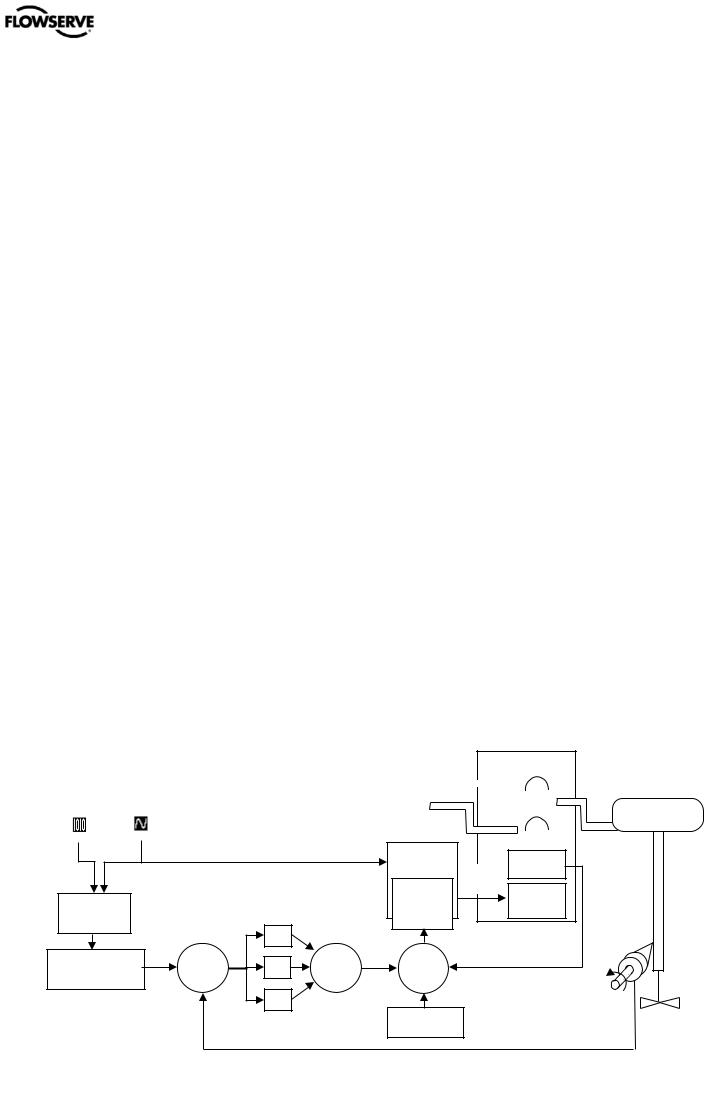
1.8Basic Operation
The Logix 500+ digital positioner is a two-wire 4-20 mA input digital valve positioner which uses the HART protocol to allow two-way remote communications. The positioner is completely powered by the 4-20 mA input signal. Start-up current must be at least 3.8 mA. The positioner is configurable through the local user interface, hand-held or DTM. The Logix 500+ positioner can control both doubleand single-acting pneumatic actuators with linear or rotary mountings.
The Logix 500+ digital positioner is an electronic and pneumatic closed-loop feedback instrument. Figure 1 shows a schematic of a Logix 500+ positioner installed on a singleacting linear actuator for air-to-open action. Figure 2 shows the feedback algorithm.
1.9HART
The Logix 500+ receives power from the two-wire, 4-20 mA input signal. However, since this positioner utilizes HART communications, two sources can be used for the command signal: Analog and Digital. In Analog source, the 4-20 mA signal is used for the command source. In Digital source, the level of the input 4-20 mA signal is ignored (used only for power) and a digital signal, sent via the HART communication protocol, is used as the command source. The command source can be accessed with ValveSight software, the HART 375 communicator, or other host software. See section 11 HART COMMUNICATION for more information.
1.10 Position Definition
Whether in Analog or Digital Source, The position at 0% is always defined as the valve in a closed position and 100% is always defined as the valve in an open position. In Analog Source, the 4-20 mA signal is converted to a position (in percent). During loop calibration, the signals corresponding to 0% and 100% are defined.
1.11 Command Input and Final Command
The Command Input signal (in percent) passes through a characterization/limits modifier block. This function is done in software, which allows for in-the-field customer adjustment. The characterization block can apply no adjustment (Linear), one of several pre-defined characterization curve adjustments (including several Equal Percent), or a 21-point Custom Characterization curve adjustment. In Linear mode, the input signal is passed straight through to the control algorithm in a 1:1 transfer. In Equal Percent (=%) mode, the input signal is mapped to a standard rangeability equal percent curve. If Custom Characterization is enabled, the input signal is mapped to a custom, user-defined 21-point output curve. The custom user-defined 21-point output curve is defined using a handheld or ValveSight software. In addition, two user-defined features, Soft Limits and Tight Shutoff may affect the position. The actual command being used to position the stem after the evaluation of characterization curves and user limits, is called the Final Command.
1.12 Outer Loop
The Logix 500+ uses a two-stage, stem-positioning algorithm. The two stages consist of an inner-loop (pilot relay control) and an outer-loop (stem position control). Referring again to Figure 1, a stem position sensor provides a measurement of the stem movement. The Final Command is compared against the Stem Position. If any deviation exists, the control algorithm sends a signal to the inner-loop control to move the relay in a direction, depending upon the deviation. The inner-loop then quickly adjusts the spool position. The actuator pressures change and the stem begins to move. The stem movement reduces the deviation between Final Command and Stem Position. This process continues until the deviation goes to zero.
|
|
|
|
Single Acting |
|
|
||||||
|
|
|
|
Pilot Relay |
|
|
||||||
|
|
|
|
|
|
|
|
|
|
|
|
|
Digital |
Analog |
|
|
|
|
|
|
|
|
|
|
|
Comman |
|
Vent |
|
|
|
|
|
|
|
|
|
|
Command |
|
|
|
|
|
|
|
|
|
|
||
|
|
|
|
|
|
|
|
|
|
|||
Input |
d Input |
|
|
Poppet |
|
|
|
|
|
|
|
|
(4-20 mA) |
Air Supply |
|
|
|
|
|
|
|
|
|||
|
|
|
Valve |
|
|
|
|
|
|
Actuator |
||
|
|
|
|
|
|
|
|
|
||||
|
|
|
|
|
|
|
|
|
|
|
|
|
|
|
|
|
|
|
|
|
|
|
|
|
|
|
|
|
|
|
|
|
|
|
|
|
|
|
|
Piezo Kill |
|
Hall |
|
Circuit |
|
|
|
|
Piezo |
Sensor |
|
Inner |
Voltage |
Piezo |
|
Loop |
|
|
Command |
|
Valve |
|
Spool |
|
||
Input |
|
|
|
Control |
|
|
|
Signal |
|
|
|
|
|
|
P
Characterization, |
+ Σ |
I |
+ |
+ |
Σ |
+ |
Σ |
_ |
|
|
Soft Limits, |
|
+ |
|
Inner-Loop |
|
|||||
Tight Shutoff |
_ |
|
|
|
Output |
|
|
Output |
|
|
|
Final |
D |
|
|
|
Percentage |
|
|
|
|
|
Command |
|
|
|
|
|
|
|
|
|
|
|
|
|
|
|
|
|
|
|
|
|
|
|
|
|
|
Inner-Loop |
|
Control |
||
|
|
|
|
|
|
|
Offset |
Position |
Valve |
|
|
|
|
|
|
|
|
|
|
Feedback |
|
Figure 1: Principles of Operation of Logix 500+
flowserve.com |
5 |
User Instructions - Logix® 500+ Series Digital Positioners FCD LGENIM0105-10 11/13
|
Double Acting |
|
Pilot Relay |
Air |
|
Supply |
Actuator |
|
Spool |
|
Valve |
|
Hall |
|
Sensor |
|
Piezo |
|
Valve |
|
Control |
|
Valve |
pressure differential causes the stem to start moving towards the desired position of 75 percent. As the stem moves, the Deviation begins to decrease. The control algorithm begins to reduce the spool opening. This process continues until the Deviation goes to zero. At this point, the spool will be back in its null or balanced position. Stem movement will stop and the desired stem position is now achieved.
1.15 Inner Loop Offset
The position of the spool (or poppet) at which the pressures are balanced, holding the valve position in a steady state, is called the Inner Loop Offset. The controlling algorithm uses this value as a reference in determining the Piezo voltage. This parameter is important for proper control and is optimized and set automatically during stroke calibration.
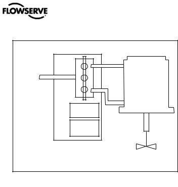
Figure 2: Double Acting Relay Operation
1.13 Inner Loop
The inner-loop controls the position of the relay valve by means of a driver module. The driver module consists of a temperature-compensated hall-effect sensor and a Piezo valve pressure modulator. The Piezo valve pressure modulator controls the air pressure under a diaphragm by means of a Piezo beam bender. The Piezo beam deflects in response to an applied voltage from the inner-loop electronics. As the voltage to the Piezo valve increases, the Piezo beam bends, closing off against a nozzle causing the pressure under the diaphragm to increase. As the pressure under the diaphragm increases or decreases, the spool or poppet valve moves up or down respectively. The Hall Effect sensor transmits the position of the spool or poppet back to the inner-loop electronics for control purposes.
1.14Detailed Sequence of Positioner Operations
A more detailed example explains the control function. Assume the unit is configured as follows:
•Unit is in Analog command source.
•Custom characterization is disabled (therefore characterization is Linear).
•No soft limits enabled. No MPC set.
•Valve has zero deviation with a present input signal of 12 mA.
•Loop calibration: 4 mA = 0% command, 20 mA = 100% command.
•Actuator is tubed and positioner is configured air-to- open.
Given these conditions, 12 mA represents a Command source of 50 percent. Custom characterization is disabled so the command source is passed 1:1 to the Final Command. Since zero deviation exists, the stem position is also at 50 percent. With the stem at the desired position, the spool valve will be at a middle position that balances the pressures above and below the piston in the actuator. This is commonly called the null or balanced spool position.
Assume the input signal changes from 12 mA to 16 mA. The positioner sees this as a command source of 75 percent. With Linear characterization, the Final Command becomes 75 percent. Deviation is the difference between Final Command and Stem Position: Deviation = 75% - 50% = +25%, where 50 percent is the present stem position. With this positive deviation, the control algorithm sends a signal to move the spool up from its present position. As the spool moves, the supply air is applied to the bottom of the actuator and air is exhausted from the top of the actuator. This new
flowserve.com |
6 |
User Instructions - Logix® 500+ Series Digital Positioners FCD LGENIM0105-10 11/13
|
|
|
10 |
|
|
|
1 |
|
|
|
11 |
|
|
|
|
|
|
12 |
|
|
2 |
|
|
|
13 |
|
|
|
|
|
|
|
14 |
|
3 |
|
|
|
|
|
21 |
|
|
|
|
|
|
|
4 |
|
|
|
|
|
22 |
|
|
|
|
|
|
|
5 |
|
|
|
|
|
23 |
|
|
|
|
|
|
|
6 |
|
|
|
|
|
24 |
7 |
|
|
|
|
|
25 |
8 |
|
|
|
|
20 |
26 |
|
|
|
|
|
||
|
|
|
|
19 |
|
|
|
|
|
|
18 |
|
|
9 |
|
15 |
16 |
17 |
|
|
1 |
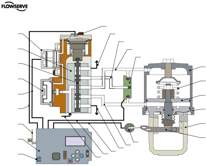
- Piezo Assembly |
10Hall Sensor Assembly |
|
15Supply In |
|
21Actuator Housing |
2 |
- Block |
11Exhaust |
|
16Pressure Sensor Cable |
22Spring |
|
3 |
- Spool |
12Port B |
|
17Feedback Cable |
23Piston |
|
4 |
- Regulator Assembly |
13Supply Pressure |
|
18Exhaust |
|
24Stem |
5 |
- Piezo Cable |
14Pressure Sensor Board |
19Port A |
|
25Yoke |
|
6 |
- Hall Sensor Cable |
|
|
20Feedback Potentiometer |
26- Take-Off Arm |
|
7 |
- Auxiliary Card |
|
|
|
|
|
8 |
- Main Board |
|
|
|
|
|
9 |
- 4-20 mA Input |
|
|
|
|
|
Figure 3: Logix 500+ Digital Positioner Schematic
(Double Acting Relay - Air To Open)
flowserve.com |
7 |

User Instructions - Logix® 500+ Series Digital Positioners FCD LGENIM0105-10 11/13
2 SPECIFICATIONS
2.1Input Signal
Table 1: Input Signal
|
Positioner Alone |
|
or with |
|
Multi-Function Card |
|
|
Power Supply |
Two-wire, 4-20 mA |
|
10.0 VDC plus line losses. |
|
|
Input Signal |
4 - 20 mA (HART) |
Range |
|
|
|
Compliance |
10.0 VDC |
Voltage |
@ 20 mA |
|
|
Effective |
500 Ω @ 20 mA Typical |
Resistance |
|
|
|
Minimum |
3.8 mA |
Required |
|
Operating Current |
|
|
|
Maximum Shut- |
3.6 mA |
down Current |
|
|
|
Communications |
HART protocol |
2.2 |
Air Supply |
|
|
|
|
Table 2: Air Supply |
|
|
Minimum Input |
1.5 Bar (22 PSI) |
|
Pressure |
|
|
|
|
|
Maximum Input |
Single Acting Relay – 6.2 Bar (90 PSI) |
|
Pressure |
Double Acting Relay – 10.3 Bar (150 PSI) |
|
|
|
|
Air Supply Quality |
The air supply must be free from moisture, |
|
|
|
oil and dust by conforming to the ISA |
|
|
7.0.01 standard. (A dew point at least 18 |
|
|
degrees Fahrenheit below ambient |
|
|
temperature, particle size below five |
|
|
microns—one micron recommended—and |
|
|
oil content not to exceed one part per |
|
|
million). |
|
|
|
Operating Humidity |
0 - 100% non-condensing |
|
|
|
|
Acceptable Supply |
Air, sweet natural gas, nitrogen and CO2 |
|
Gasses |
are acceptable supply gasses. |
|
|
|
Sour natural gas is not acceptable. |
|
|
|
Air Consumption |
Single Acting Relay – |
|
|
|
0.069 Nm³/h @ 1.5 bar |
|
|
(0.041 SCFM @ 22 PSI) |
|
|
0.082 Nm³/h @ 4.1 bar |
|
|
(0.050 SCFM @ 60 PSI) |
|
|
Double Acting Relay – |
|
|
0.297 Nm³/h @ 1.5 bar |
|
|
(0.175 SCFM @ 22 PSI) |
|
|
0.637 Nm³/h @ 4.1 bar |
|
|
(0.375 SCFM @ 60 PSI) |
|
|
|
2.3Pneumatic Output
Table 3: Pneumatic Output
Output Pressure |
0 to 100% of air supply pressure. |
Range |
|
|
|
Output Air Capacity |
Single Acting Relay – |
|
9.06 Nm³/h @ 1.5 bar |
|
(5.33 SCFM @ 22 PSI) |
|
20.8 Nm³/h @ 4.1 bar |
|
(12.2 SCFM @ 60 PSI) |
|
Double Acting Relay – |
|
14.3 Nm³/h @ 1.5 bar |
|
(8.44 SCFM @ 22 PSI) |
|
30.6 Nm³/h @ 4.1 bar |
|
(18.0 SCFM @ 60 PSI) |
|
|
Primary Output Ports |
Single Acting Relay – Port B |
(Port is pressurized in |
Double Acting Relay – Port A |
energized state. Port |
|
is exhausted upon loss |
|
of power.) |
|
|
|
2.4Stroke Output
Table 4: Stroke Output
Feedback shaft |
Min 15°, Max 90° |
|
Rotation |
45° recommended for linear applications. |
|
|
|
|
2.5Analog Output – Multi-Function Card
Table 5: 4 to 20 mA Analog Output Specification
For entity parameters, see section 3 HAZARDOUS AREA
CERTIFICATIONS.
Power Supply Range |
10.0 to 40 VDC, (24 VDC Typical) |
|
|
Current Signal Output |
4 to 20 mA |
|
|
Linearity |
1.0% F.S. |
|
|
Repeatability |
0.25% F.S. |
|
|
Hysteresis |
1.0% F.S. |
|
|
Operating Temperature |
-52 to 85°C (-61.6 to 185°F) |
|
|
2.6Remote Mount Specifications
Table 6: Remote Mount Specifications
For entity parameters, see section 3 HAZARDOUS AREA
CERTIFICATIONS.
Remote Mount Device |
Use only with Logix® Remote |
|
Mount Option device. |
||
|
||
Max Cable and Tube Distance |
30.5 m (100 ft) |
|
|
|
|
Operating Temperature |
-52 to 85°C (-61.6 to 121°F) |
|
|
|
flowserve.com |
8 |

User Instructions - Logix® 500+ Series Digital Positioners FCD LGENIM0105-10 11/13
2.7Limit Switch Specifications
Table 7: Limit Switch Specifications
For entity parameters, see section 3 HAZARDOUS AREA
CERTIFICATIONS.
Switch |
Specifications |
|
|
||
|
|
|
Mechanical |
Load Current: |
3/2 AAC/ADC |
Cherry DG 13-B(X)RA |
Voltage: |
125/30 VAC/VDC |
NO and/or NC |
Temperature: |
-25 to +85 °C |
General Purpose Only |
|
(-13 °F to 185 °F) |
|
|
|
Reed |
Load Current: |
500 mA |
Hamlin 59050-030 |
Voltage: |
200VDC |
NO |
Temperature: |
-40 to +105 °C |
|
|
(-40 °F to 221 °F) |
|
|
|
Inductive Sensor |
Load Current: |
Plate: ≤ 1 mA; |
P&F NJ2-V3-N |
|
No Plate: ≥ 3 mA |
NAMUR NC -3 |
Voltage: |
Nominal 8.2 VDC |
|
Temperature: |
-25 °C to 100 °C |
|
|
(-13 °F to 212 °F) |
Inductive Proximity |
Load Current: |
Plate: ≤ 1 mA; |
P&F SJ2-S1N |
|
No Plate: ≥ 3 mA |
NAMUR NO-4 |
Voltage: |
5-25 VDC |
|
|
(Nominal 8 VDC) |
|
Temperature: |
-25 °C to 100 °C |
|
|
(-13 °F to 212 °F) |
|
|
|
Inductive Proximity |
Load Current: |
Plate: ≤ 1 mA; |
P&F SJ2-SN |
|
No Plate: ≥ 3 mA |
NAMUR NC-5 |
Voltage: |
5-25 VDC |
|
|
(Nominal 8 VDC) |
|
Temperature: |
-40 °C to 100 °C |
|
|
(-40 °F to 212 °F) |
Inductive Sensor |
Load Current: |
0…100 mA |
P&F NBB2-V3-E2 |
Voltage: |
10...30 VDC |
PNP NO |
Temperature: |
-25 °C to 70 °C |
General Purpose Only |
|
(-13 °F to 158 °F) |
|
|
|
2.8Positioner Performance Characteristics
Table 8: Performance Characteristics
Better than or equal to the following values on a 25 square inch
Mark I actuator.
Resolution |
≤ 0.25% |
Linearity |
+/-1.25% |
|
|
Repeatability |
≤ 0.25% |
Hysteresis |
≤ 1.0% |
Deadband |
≤ 0.3% |
Sensitivity |
≤ 0.25% |
Stability |
≤ 0.4% |
Long term drift |
≤ 0.5% |
Supply Pressure Effect |
≤ 0.2% |
|
|
NOTE: Performance tested according to ISA 75.13.
2.9Physical Specifications
Table 9: Physical Specifications
For dimensions, see section 19 POSITIONER .
Housing Material |
Cast, powder-painted aluminum |
|
EN AC-AlSi12(Fe) |
Soft Goods |
Fluorosilicone |
|
|
Weight of Base |
With Single Acting Relay |
Positioner Without |
1.76 kg (3,88 lb) |
Accessories |
With Double Acting Relay |
|
|
|
1.88 kg (4.14 lb) |
2.10 Temperature
Table 10: Temperature
Operating Temperature -52 to 85°C (-61.6 to 185°F) Range
Transport and Storage -52 to 85°C (-61.6 to 185°F) Range
NOTE: Reduced performance possible at low temperatures.
2.11ValveSight DTM Software Specifications
Table 11: ValveSight DTM Software Specifications
Computer |
Minimum Pentium processor running |
|
Windows 95, 98, NT, 2000, XP, 7, 32 MB |
|
total memory (64 MB recommended), 30 |
|
MB available hard disk space, CD-ROM |
|
drive |
|
|
Ports |
1 minimum available with 8 maximum |
|
possible. (Can also communicate via |
|
serial, PCMCIA and USB connections) |
|
|
HART Modem |
RS-232, |
|
PCMCIA card, or |
|
USB |
|
|
HART Filter |
May be required in conjunction with some |
|
DCS hardware. |
|
|
HART MUX |
MTL 4840/ELCON 2700 |
|
|
flowserve.com |
9 |

User Instructions - Logix® 500+ Series Digital Positioners FCD LGENIM0105-10 11/13
3 HAZARDOUS AREA CERTIFICATIONS
|
DANGER: Certifications listed on the positioner are correct for that positioner. Before using the information on this page, |
|||||||||||||||||||||
|
ensure the certifications on the positioner label match the certifications on this page. |
|
|
|
|
|
|
|
||||||||||||||
|
Table 12: Logix 500+ Series Hazardous Locations Information |
|
|
|
|
|
|
|
|
|
|
|
|
|
||||||||
|
|
|
|
|
ATEX |
|
|
|
|
|
Intrinsically Safe |
North America (cFMus) |
|
|
|
|||||||
|
|
|
|
|
|
|
|
|
|
|
|
|
|
|
|
|
|
|
|
|||
|
Intrinsically Safe |
|
|
|
|
|
|
|
|
Class I, Div 1, Groups A,B,C,D |
|
|
|
|
|
|||||||
|
FM12ATEX0009X |
|
|
|
|
|
|
|
|
Class I, Zone 0, AExia IIC (US) |
|
|
|
|
|
|||||||
|
II 1 G |
|
|
|
|
|
|
|
|
|
|
Class I, Zone 0, Ex ia IIC (Canada) |
|
|
|
|
|
|||||
|
Ex ia IIC Ga T4/T6 |
|
|
|
|
|
|
|
T4 Tamb = -20˚C ≤ Ta ≤ +85˚C |
|
|
|
|
|
||||||||
|
T4 Tamb = -20˚C ≤ Ta ≤ +85˚C |
|
|
|
|
|
|
T6 Tamb = -52˚C ≤ Ta ≤ +45˚C |
|
|
|
|
|
|||||||||
|
T6 Tamb = -52˚C ≤ Ta ≤ +45˚C |
|
|
|
|
|
|
Type 4X |
|
|
|
|
|
|
|
|
|
|
||||
|
IP 66 |
|
|
|
|
|
|
|
|
|
|
|
|
|
|
|
|
|
|
|
|
|
|
|
|
|
|
|
|
|
|
|
|
|
Entity |
|
4-20 |
|
|
Limit |
|
Remote |
|
|
|
|
|
|
|
|
|
Limit |
|
|
|
|
|
|
MFC |
|
Switches |
|
|
|
||||
|
Entity |
|
4-20 |
|
|
Remote |
|
|
|
Parameters |
|
Input |
|
|
Mount |
|
|
|||||
|
|
MFC |
Switches |
|
|
|
|
|
|
|
|
|
|
|
||||||||
|
Parameters |
|
Input |
|
Mount |
|
|
|
|
|
|
|
|
|
-02 |
|
|
|
|
|||
|
|
|
|
|
|
|
|
|
|
|
|
|
|
|
|
|
|
|||||
|
|
|
|
|
|
-02 |
|
|
|
|
|
Ui (Vdc)= |
|
30 |
30 |
|
10.6 |
|
Vo = 5V |
|
|
|
|
Ui (Vdc)= |
|
30 |
30 |
10.6 |
|
Vo = 5V |
|
|
|
|
|
|
|
|
|||||||
|
|
|
|
|
|
|
|
|
|
|
|
|
|
|
|
|
||||||
|
|
|
|
|
|
Ii (mA)= |
|
100 |
100 |
|
29.7 |
|
Io = 79mA |
|
|
|||||||
|
|
|
|
|
|
|
|
|
|
|
|
|
|
|
|
|
||||||
|
Ii (mA)= |
|
100 |
100 |
29.7 |
|
Io = 79mA |
|
||||||||||||||
|
|
|
|
|
|
|
|
|
|
|
|
|
|
|
|
|
||||||
|
|
|
|
|
|
Pi (mW)= |
|
800 |
800 |
|
79 |
|
Po = 129mW |
|
|
|||||||
|
|
|
|
|
|
|
|
|
|
|
|
|
|
|
|
|
||||||
|
Pi (mW)= |
|
800 |
800 |
79 |
|
Po = 129mW |
|
||||||||||||||
|
|
|
|
|
|
|
|
|
|
|
|
|
|
|
|
|
||||||
|
|
|
|
|
|
Ci (nF)= |
|
0 |
0 |
|
1 |
|
Co = 2uF |
|
|
|||||||
|
|
|
|
|
|
|
|
|
|
|
|
|
|
|
|
|
||||||
|
Ci (nF)= |
|
0 |
0 |
1 |
|
Co = 2uF |
|
||||||||||||||
|
|
|
|
|
|
|
|
|
|
|
|
|
|
|
|
|
||||||
|
|
|
|
|
|
Li (µH)= |
|
47 |
0 |
|
1 |
|
Lo = 100uH |
|
|
|||||||
|
|
|
|
|
|
|
|
|
|
|
|
|
|
|
|
|
||||||
|
Li (µH)= |
|
47 |
0 |
1 |
|
Lo = 100uH |
|
||||||||||||||
|
|
|
|
|
|
|
|
|
|
|
|
|
|
|
|
|
||||||
|
|
|
|
|
|
Non-Incendive |
|
|
|
|
|
|
|
|
||||||||
|
|
|
|
|
|
|
|
|
|
|
|
|
|
|
|
|
|
|
|
|||
|
|
|
|
|
|
|
|
|
|
|
|
|
|
|
|
|
|
|||||
|
|
|
|
|
|
|
|
|
|
|
|
Class I, Div 2, Groups A,B,C,D, |
|
|
|
|
|
|||||
|
|
|
|
|
|
|
|
|
|
|
|
T4 Tamb = -20˚C ≤ Ta ≤ +85˚C |
|
|
|
|
|
|||||
|
|
|
|
|
|
|
|
|
|
|
|
T6 Tamb = -52˚C ≤ Ta ≤ +45˚C |
|
|
|
|
|
|||||
|
|
|
|
|
|
|
|
|
|
|
|
Type 4X |
|
|
|
|
|
|
|
|
|
|
|
|
|
|
|
|
|
|
|
|
|
|
Barriers Not Required when installed per the NEC/CEC |
|
|||||||||
|
|
|
|
|
IECEx |
|
|
|
|
|
Notes |
Reference installation drawing # 291780 |
|
|
|
|||||||
|
|
|
|
|
|
|
|
|
|
• |
|
|
|
|||||||||
|
Intrinsically Safe |
|
|
|
|
|
|
|
|
Warning! |
|
|
|
|
|
|
|
|
|
|
||
|
FMG 12.0001X |
|
|
|
|
|
|
|
|
Limit Switch options -01, -03, -04, -05, -06 are not rated for |
|
|||||||||||
|
|
|
|
|
|
|
|
|
• |
|
||||||||||||
|
Ex ia IIC Ga T4/T6 |
|
|
|
|
|
|
|
|
|||||||||||||
|
|
|
|
|
|
|
|
|
use in hazardous areas. Select these options only when |
|
||||||||||||
|
T4 Tamb = -20˚C ≤ Ta ≤ +85˚C |
|
|
|
|
|
|
|
|
|||||||||||||
|
|
|
|
|
|
|
|
installing in non-explosive atmospheres. |
|
|
|
|||||||||||
|
T6 Tamb = -52˚C ≤ Ta ≤ +45˚C |
|
|
|
|
|
|
|
|
|
|
|||||||||||
|
|
|
|
|
|
|
• |
Covers must be properly installed in order to maintain |
|
|||||||||||||
|
IP 66 |
|
|
|
|
|
|
|
|
|
|
|
||||||||||
|
|
|
|
|
|
|
|
|
|
|
|
environmental ratings. |
|
|
|
|
|
|||||
|
Entity |
|
4-20 |
|
Limit |
|
Remote |
|
|
|
|
|
|
|
|
|
||||||
|
|
|
|
|
|
Special Conditions for Safe Use: |
|
|
|
|
|
|||||||||||
|
|
MFC |
Switches |
|
|
|
|
|
|
|
|
|||||||||||
|
Parameters |
|
Input |
|
Mount |
|
|
|
|
|
|
|
||||||||||
|
|
|
|
|
|
|
|
• |
The equipment must be installed in such a manner as to |
|
||||||||||||
|
|
|
|
|
|
-02 |
|
|
|
|
|
|
||||||||||
|
|
|
|
|
|
|
|
|
|
|
|
minimize the risk of impact or friction with other metal |
|
|||||||||
|
Ui (Vdc)= |
|
30 |
30 |
10.6 |
|
Vo = 5V |
|
|
|
|
|
||||||||||
|
|
|
|
|
|
|
surfaces. |
|
|
|
|
|
|
|
||||||||
|
|
|
|
|
|
|
|
|
|
|
|
• |
To avoid possibility of static discharge clean only with a |
|
||||||||
|
Ii (mA)= |
|
100 |
100 |
29.7 |
|
Io = 79mA |
|
|
|
|
|||||||||||
|
|
|
|
|
|
|
damp Cloth |
|
|
|
|
|
|
|
||||||||
|
|
|
|
|
|
|
|
|
|
|
|
• |
For Intrinsically Safe installations the positioner must be |
|
||||||||
|
Pi (mW)= |
|
800 |
800 |
79 |
|
Po = 129mW |
|
|
|
|
|||||||||||
|
|
|
|
|
|
|
connected to suitably rated intrinsically safe equipment, |
|
||||||||||||||
|
|
|
|
|
|
|
|
|
|
|
|
|
and must be installed in accordance with applicable |
|
||||||||
|
|
|
|
|
|
|
|
|
|
|
|
|
|
|||||||||
|
Ci (nF)= |
|
0 |
0 |
1 |
|
Co = 2uF |
|
|
|
|
intrinsically safe installation standards. |
|
|
|
|||||||
|
|
|
|
|
|
|
|
|
|
|
|
• |
Substitution of components may impair Intrinsic Safety. |
|
||||||||
|
Li (µH)= |
|
47 |
0 |
1 |
|
Lo = 100uH |
|
|
|
|
|||||||||||
|
|
|
|
|
|
• |
Use appropriately rated cable insulation at higher |
|
||||||||||||||
|
|
|
|
|
|
|
|
|
|
|
|
|
temperatures. |
|
|
|
|
|
|
|
||
|
|
|
|
|
|
|
|
|
|
|
|
|
|
|
|
|
|
|
|
|||
|
|
|
|
|
|
|
|
|
|
|
|
|
|
|
||||||||
|
Conditions spéciales pour une utilisation en toute sécurité: |
|
|
|
|
|
|
|
|
|
|
|
|
|
||||||||
|
• |
Le matériel doit être installé de sorte à réduire au minimum le risque de choc ou de frottement avec d'autres surfaces métalliques. |
|
|||||||||||||||||||
|
• |
Pour éviter les risques de décharge d'électricité statique Nettoyez uniquement avec un chiffon humide |
|
|
|
|||||||||||||||||
|
• |
Pour les installations en sécurité intrinsèque, le positionneur doit être connecté à un équipement sécurité intrinsèque |
|
|||||||||||||||||||
|
|
convenablement qualifié, et doit être installé conformément aux normes d'installation sécurité intrinsèque applicables. |
|
|||||||||||||||||||
|
• |
La substitution de composants peut compromettre la sécurité intrinsèque. |
|
|
|
|
|
|
|
|
||||||||||||
|
• |
Utiliser une isolation appropriée du câble à des températures plus élevées. |
|
|
|
|
|
|
|
|
||||||||||||
|
|
|
|
|
|
|
|
|
|
|
|
|
|
|
|
|
|
|
|
|||
|
|
flowserve.com |
|
|
|
|
10 |
|
|
|
|
|
|
|
|
|
|
|||||
User Instructions - Logix® 500+ Series Digital Positioners FCD LGENIM0105-10 11/13
4 STORAGE AND UNPACKING
4.1Storage
FLOWSERVE Control valve packages (a control valve and its instrumentation) are typically well protected from corrosion. Nevertheless FLOWSERVE products must be stored in a clean, dry environment such as an enclosed building that affords environmental protection. Heating is not required. Control valve packages must be stored on suitable skids, not directly on the floor. The storage location must also be free from flooding, dust, dirt, etc. Plastic caps are fitted to protect the flange faces and positioner ports to prevent the ingress of foreign materials. These caps should not be removed until the valve or positioner is actually mounted into the system.
If FLOWSERVE products (especially sealing materials) have been in storage for longer periods check these for corrosion or deterioration before using these products. Fire protection for FLOWSERVE products must be provided by the end user.
4.2Unpacking
While unpacking the valve and/or Logix 500MD+ positioner, check the packing list against the materials received. Lists describing the system and accessories are included in each shipping container.
In the event of shipping damage, contact the shipper immediately. Should any problems arise, contact a Flowserve Flow Control Division representative.
4.3Pre-installation Inspection
When installing a positioner, verify the shaft has not been damaged and that the plugs and cover are in place. The plugs keep debris and moisture from damaging the internal components of the positioner. If the positioner has been contaminated, clean the positioner components gently with a soft damp cloth. Some components may be removed for better access. See section 17 MAINTENANCE AND REPAIR. When cleaning a Double Acting Relay (Spool and Block) take care not to bend or force the spool. A Single Acting Relay may be removed, but do not disassembled the relay. Check connectors to ensure that no debris is present. Port screens can be removed with a flat screwdriver for access to internal passages.
flowserve.com |
11 |
User Instructions - Logix® 500+ Series Digital Positioners FCD LGENIM0105-10 11/13
5 MOUNTING AND INSTALLATION
5.1Mounting to Mark One Linear Valves
To mount a Logix 500+ positioner to a Valtek linear Mark One valve, refer to Figure 4: Mounting to Mark I Linear Valves and proceed as outlined below.
1Remove washer and nut from follower pin assembly. Insert pin into the appropriate hole in follower arm, based on stroke length. The stroke lengths are stamped next to their corresponding holes in the follower arms. Make sure the unthreaded end of the pin is on the stamped side of the arm. Reinstall lock washer and tighten nut to complete follower arm assembly.
2Slide the slot in the follower arm assembly over the flats on the position feedback shaft in the back of the positioner. Make sure the arm is pointing toward the side of the positioner with ports A, B, and Supply. Slide the lock washer over the threads on the shaft and tighten down the nut.
3Align the bracket with the three outer mounting holes on the positioner. Fasten with 1/4" bolts.
4Screw one mounting bolt into the hole on the yoke mounting pad nearest the cylinder. Stop when the bolt is approximately 3⁄16" from being flush with mounting pad.
5Slip the large end of the teardrop shaped mounting hole in the back of the positioner/bracket assembly over the mounting bolt. Slide the small end of the teardrop under the mounting bolt and align the lower mounting hole.
Bracket
Positioner
Feedback
Shaft
Follower Arm
Follower Pin
6Insert the lower mounting bolt and tighten the bolting.
7Position the take-off arm mounting slot against the stem clamp mounting pad. Apply Loctite 222 to the take-off arm bolting and insert through washers into stem clamp. Leave bolts loose.
8Slide the appropriate pin slot of the take-off arm, based on stroke length, over the follower arm pin. The appropriate stroke lengths are stamped by each pin slot.
NOTE: The feedback shaft has a clutch mechanism that allows for over-rotation of the shaft for easy adjustments.
9Center the take-off arm on the rolling sleeve of the follower pin.
10Align the take-off arm with the top plane of the stem clamp and tighten bolting. Torque to 120 in-lb.
NOTE: If mounted properly, the follower arm should be horizontal when the valve is at 50% stroke and should move approximately ±30° from horizontal over the full stroke of the valve. If mounted incorrectly, a stroke calibration error will occur and the indicator lights will blink a RGGY code indicating the position sensor has gone out of range on one end of travel or the travel is too small. Reposition the feedback linkage or rotate the position sensor to correct the error.
NOTE: To virtually eliminate non-linearity, use the Linearization feature in the Custom Characterization page of the DTM.
|
|
|
|
|
|
|
|
|
|
|
|
|
|
|
|
|
|
|
|
|
|
|
|
|
|
|
|
Take-Off Arm |
|
|
|
|
|
|
|
Take-Off Arm |
Stem Clamp |
||||
|
||||||
Pin Slot |
|
|
|
|
|
|
Figure 4: Mounting to Mark I Linear Valves
flowserve.com |
12 |
User Instructions - Logix® 500+ Series Digital Positioners FCD LGENIM0105-10 11/13
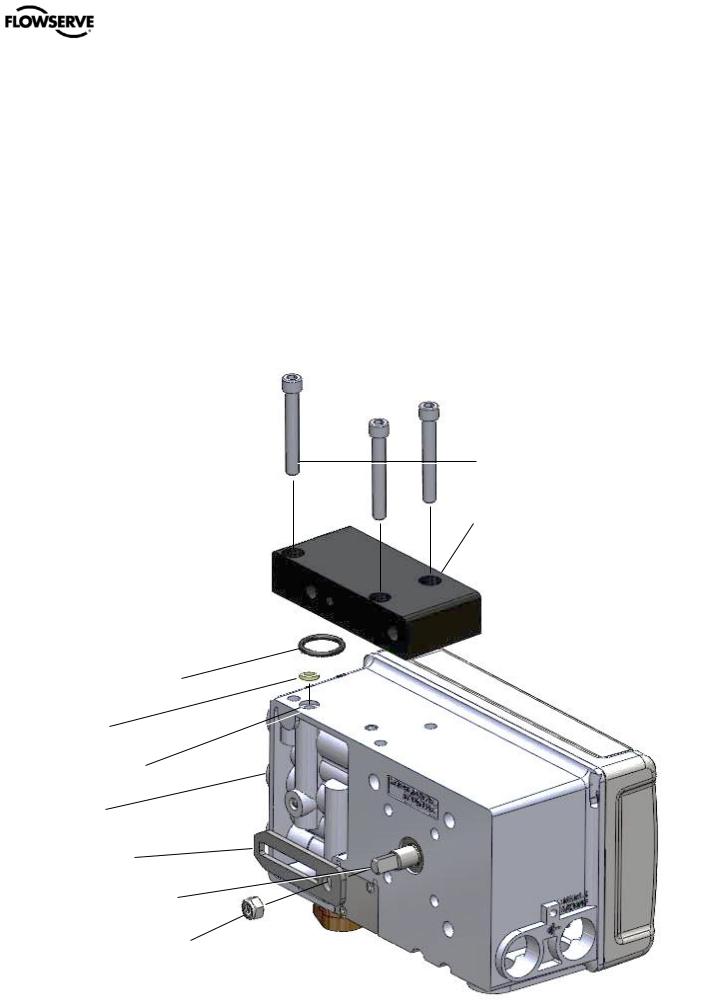
5.2Mounting to FlowTop Linear Valves
To mount a Logix 500+ positioner to a FlowTop linear actuator and valve (with direct mounting / integrated tubing), proceed as outlined below.
1Remove the FlowTop port plug screw. Plug port B.
2Ensure positioner O-ring surface is clean. Then install the O-ring, and FlowTop mounting block using the positioner screws.
3Attach the follower arm to the feedback shaft using the follower arm nut.
 Positioner Screws
FlowTop Mounting Bracket
Positioner O-ring
Spacer
FlowTop Port
Port B
Follower Arm
Feedback Shaft
Follower Arm Nut
Figure 5: FlowTop Mounting Bracket
flowserve.com |
13 |
User Instructions - Logix® 500+ Series Digital Positioners FCD LGENIM0105-10 11/13
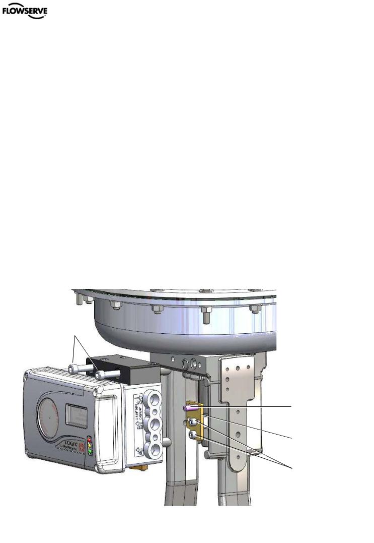
Refer to Figure 6: FlowTop Mounting.
4Assemble the take-off pin to the take-off plate and mount the take-off plate to the valve stem using the two screws. Adjust the follower pin to match the correct location as indicated on the follower arm’s embossed scale.
5Place the actuator O-ring.
6Place the positioner on the actuator, ensuring the takeoff pin is inside the follower arm slot. Adjust the follower arm as needed.
NOTE: The feedback shaft has a clutch mechanism that allows for over-rotation of the shaft for easy adjustments.
7Use the actuator screws to secure the positioner in place.
8Connect regulated air supply to appropriate port in manifold. See section 6 TUBING.
9Connect the power to the 4-20 mA terminals. See section 7 ELECTRICAL CONNECTIONS.
10Remove main cover and locate DIP switches and QUICK-CAL/ACCEPT button.
12Press the QUICK-CAL/ACCEPT button for three to four seconds or until the positioner begins to move. The positioner will now perform a stroke calibration.
13If the calibration was successful the green LED will blink GGGG or GGGY and the valve will be in control mode.
14If calibration fails, as indicated by a RGGY blink code, retry the calibration. If it still fails, the feedback values were exceeded and the arm must be adjusted away from the positioner’s limits. Rotate the feedback shaft so that the full free travel of the feedback shaft is in the range of the actuator movement. Optionally, continue to attempt the calibration. Each calibration attempt adjusts the acceptable limits and it should pass eventually.
 CAUTION: Remember to remove the air supply before re-adjusting take-off arm.
NOTE: If mounted properly, the follower arm should be horizontal when the valve is at 50% stroke and should move approximately ±30° from horizontal over the full stroke of the valve.
11Refer to sticker on main board cover and set DIP switches accordingly. See section 8 STARTUP.
Actuator Screws
NOTE: To virtually eliminate non-linearity, use the Linearization feature on the Custom Characterization page of the DTM.
 Actuator O-ring
Take-Off Pin
Take-Off Plate
Take-Off Plate Screws
Figure 6: FlowTop Mounting
flowserve.com |
14 |
User Instructions - Logix® 500+ Series Digital Positioners FCD LGENIM0105-10 11/13
5.3Mounting to Standard Valtek Rotary Valves
The standard rotary mounting applies to Valtek valve/actuator assemblies that do not have mounted volume tanks or hand-wheels. The standard mounting uses a linkage directly coupled to the valve shaft. This linkage has been designed to allow for minimal misalignment between the positioner and the actuator.
1Fasten the spline lever adapter to the splined lever using two 6 x 1/2" self-tapping screws.
2Slide the take-off arm onto the spline lever adapter shaft, orienting the arm to the current valve position. Insert the screw with star washer through the take-off arm and add the second star washer and nut and tighten.
Spline
Lever
Adapter
Take-Off
Arm
Assembly
Figure 8: Valtek Rotary Take-Off Arm
3Attach follower arm to positioner feedback shaft using the star washer and 10-32 nut.
Feedback Shaft
Follower Arm
Universal
Bracket
Figure 9: Valtek Rotary Follower Arm
4Rotate the follower arm so the follower pin will slide into the slot on the take-off arm. Adjust the bracket position as needed noting the engagement of the follower pin and the take-off arm slot. The pin should extend approximately 2 mm past the take-off arm. When properly adjusted, securely tighten the bracketing bolts
5Using four 1/4-20 x 1/2" bolts, fasten positioner to universal bracket using appropriate hole pattern (stamped on bracket).
6
7Using a ½” end wrench and two 5/16-18 X ½” bolts, attach bracket to actuator transfer case pad. Leave
Figure 7: Valtek Rotary Mounting
these bolts slightly loose until final adjustments are made.
8Rotate follower arm so the follower pin will slide into the slot on the take-off arm. Over-rotate the follower arm if needed so the arm moves freely through the intended travel.
NOTE: The feedback shaft has a clutch mechanism that allows for over-rotation of the shaft for easy adjustments.
9Adjust the bracket position as needed noting the engagement of the follower pin and the take-off arm slot. The pin should extend approximately 1⁄16" past the take-off arm. When properly adjusted, securely tighten the bracketing bolts.
10Connect regulated air supply to appropriate port in manifold. See section 6 TUBING.
11Connect the power to the 4-20 mA terminals. See section 7 ELECTRICAL CONNECTIONS.
12Remove main cover and locate DIP switches and QUICK-CAL/ACCEPT button.
13Refer to sticker on main board cover and set DIP switches accordingly. See section 8 STARTUP.
14Press the QUICK-CAL/ACCEPT button for three to four seconds or until the positioner begins to move. The positioner will now perform a stroke calibration.
15If the calibration was successful the green LED will blink GGGG or GGGY and the valve will be in control mode.
16If calibration fails, as indicated by a RGGY blink code, retry the calibration. If it still fails, the feedback values
flowserve.com |
15 |
User Instructions - Logix® 500+ Series Digital Positioners FCD LGENIM0105-10 11/13
were exceeded and the arm must be adjusted away from the positioner’s limits. Rotate the feedback shaft so that the full free travel of the feedback shaft is in the range of the actuator movement. Optionally, continue to attempt the calibration. Each calibration attempt adjusts the acceptable limits and it should pass eventually.
 CAUTION: Remember to remove the air supply before re-adjusting take-off arm.
NOTE: If mounted properly, the follower arm should be horizontal when the valve is at 50% stroke and should move approximately ±30° from horizontal over the full stroke of the valve.
NOTE: To virtually eliminate non-linearity, use the Linearization feature on the Custom Characterization page of the DTM.
Figure 10: Valtek Rotary Final Orientation
flowserve.com |
16 |

User Instructions - Logix® 500+ Series Digital Positioners FCD LGENIM0105-10 11/13
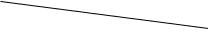
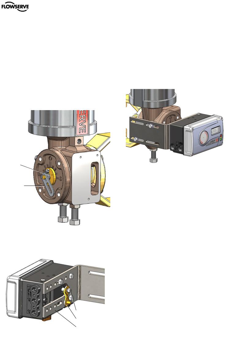
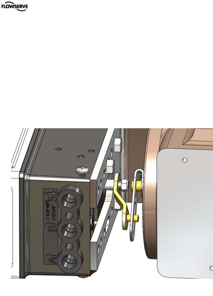
5.4Mounting to MaxFlo Rotary Valves
1Slide the take-off arm onto the shaft. Insert the screw with star washer through the take-off arm and add the second star washer and nut. Tighten nut with socket so arm is lightly snug on the shaft but still able to rotate. This will be tightened after linkage is correctly oriented.
Take-Off Arm
 Take-Off Pin
Figure 11: MaxFlo Take-Off Arm
2Attach the mounting plate to the positioner using 4 screws.
3Attach follower arm to positioner feedback shaft.
Mounting Plate
 Feedback Shaft
 Follower Arm
Figure 13: MaxFlo Follower Arm
4Rotate the follower arm so the take-off pin will slide into the slot on the follower arm. Adjust the bracket position as needed noting the engagement of the follower pin and the take-off arm slot. The pin should extend approximately 2 mm past the take-off arm. When properly adjusted, securely tighten the bracketing bolts.
NOTE: The feedback shaft has a clutch mechanism that allows for over-rotation of the shaft for easy adjustments.
Figure 14: MaxFlo Connection
5Connect regulated air supply to appropriate port in manifold. See section 6 TUBING.
6Connect the power to the 4-20 mA terminals. See section 7 ELECTRICAL CONNECTIONS.
7Remove main cover and locate DIP switches and QUICK-CAL/ACCEPT button.
8Refer to sticker on main board cover and set DIP switches accordingly. See section 8 STARTUP.
9Press the QUICK-CAL/ACCEPT button for three to four seconds or until the positioner begins to move. The positioner will now perform a stroke calibration.
10If the calibration was successful the green LED will blink GGGG or GGGY and the valve will be in control mode.
11If calibration fails, as indicated by a RGGY blink code, retry the calibration. If it still fails, the feedback values were exceeded and the arm must be adjusted away from the positioner’s limits. Rotate the feedback shaft so that the full free travel of the feedback shaft is in the range of the actuator movement. Optionally, continue to attempt the calibration. Each calibration attempt adjusts the acceptable limits and it should pass eventually.
 CAUTION: Remember to remove the air supply before re-adjusting take-off arm.
Figure 12: MaxFlo Assembly
flowserve.com |
17 |
User Instructions - Logix® 500+ Series Digital Positioners FCD LGENIM0105-10 11/13
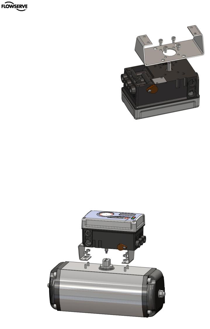
5.5Mounting to Rotary NAMUR (AutoMax) Valves
1Attach the mounting plate to the positioner using 4 screws.
2Rotate the feedback shaft to match the orientation of the receiver on the actuator.
NOTE: The feedback shaft has a clutch mechanism that allows for over-rotation of the shaft for easy adjustments.
3Mount the positioner onto the actuator using the washers and nuts.
4Connect regulated air supply to appropriate port in manifold. See section 6 TUBING.
5Connect the power to the 4-20 mA terminals. See section 7 ELECTRICAL CONNECTIONS.
6Remove main cover and locate DIP switches and QUICK-CAL/ACCEPT button.
7Refer to sticker on main board cover and set DIP switches accordingly. See section 8 STARTUP.
8 Press the QUICK-CAL/ACCEPT button for three to four |
Figure 15: AutoMax Bracket |
|
seconds or until the positioner begins to move. The positioner will now perform a stroke calibration.
9If the calibration was successful the green LED will blink GGGG or GGGY and the valve will be in control mode.
10If calibration fails, as indicated by a RGGY blink code, retry the calibration. If it still fails, remove power from the positioner, disconnect the air, and remove the positioner from the actuator. Rotate the feedback shaft so that the full free travel of the feedback shaft is in the range of the actuator movement. Optionally, continue to attempt the calibration. Each calibration attempt adjusts the acceptable limits and it should pass eventually.
 CAUTION: Remember to remove the air supply before re-adjusting take-off arm.
Figure 16: AutoMax Assembly
flowserve.com |
18 |
User Instructions - Logix® 500+ Series Digital Positioners FCD LGENIM0105-10 11/13
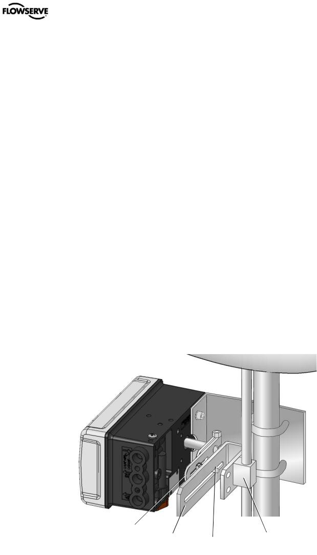
5.6Mounting to a Linear NAMUR Pneumatic Actuator
The mounting of a rod actuator kit and actuator (according to IEC 534 part 6) is described in the following example.
1Mount the follower arm by unscrewing the lock nut for the follower arm attachment. Place the follower arm on the shaft at the back of the positioner and fasten it with the lock nut. The follower pin should point away from the positioner.
2Attach the stem clamp bracket to the stem clamp and fasten it with two hexagon socket screws and lock washers.
3Attach the take-off arm to the stem clamp bracket and fasten it with a hexagon socket caps crew and a washer.
 CAUTION: Maximum torque 0,25 Nm (0,18 ft-lbs).
4To mount the positioner, adjust the actuator to midstroke.
5Pre-assemble the mounting bracket on the left actuator leg and hand-tighten the two U-bolts, nuts and lockwashers.
6Attach the positioner to the pre-assembled mounting bracket and fasten it with two hexagon screws and two lock washers. Check that the follower pin is inserted in the slot of the take-off arm and the follower arm is positioned parallel to the take-off arm.
7Tighten all screws and nuts.
NOTE: The feedback shaft has a clutch mechanism that allows for over-rotation of the shaft for easy adjustments.
NOTE: A slight unsymmetrical mounting increases
the linearity deviation but does not affect the performance of the device.
NOTE: Depending on the actuator size and stroke it may be necessary to flip the take-off arm (Figure 3) by 180° and attach it to the opposite side of the stem clamp bracket.
8Connect regulated air supply to appropriate port in manifold. See section 6 TUBING.
9Connect the power to the 4-20 mA terminals. See section 7 ELECTRICAL CONNECTIONS.
10Remove main cover and locate DIP switches and QUICK-CAL/ACCEPT button.
11Refer to sticker on main board cover and set DIP switches accordingly. See section 8 STARTUP.
12Press the QUICK-CAL/ACCEPT button for three to four seconds or until the positioner begins to move. The positioner will now perform a stroke calibration.
13If the calibration was successful the green LED will blink GGGG or GGGY and the valve will be in control mode.
14If calibration fails, as indicated by a RGGY blink code, retry the calibration. If it still fails, remove power from the positioner, disconnect the air, and remove the positioner from the actuator. Rotate the feedback shaft so that the full free travel of the feedback shaft is in the range of the actuator movement. Optionally, continue to attempt the calibration. Each calibration attempt adjusts the acceptable limits and it should pass eventually.
 CAUTION: Remember to remove the air supply before re-adjusting take-off arm.
Follower Arm
Take Off Arm |
Stem Clamp |
|
Follower Pin |
Figure 17: Mounting to a Linear Actuator
flowserve.com |
19 |
User Instructions - Logix® 500+ Series Digital Positioners FCD LGENIM0105-10 11/13
6 TUBING
After mounting has been completed, tube the positioner to the actuator using the appropriate compression fitting connectors. For best performance, use 10 mm (3/8 inch) tubing for 645 square cm (100 square inch) actuators or larger.
regardless of air action. On rotary actuators, the transfer case orientation determines the air action.
6.1Determine Air Action
The port labeled “Y1” delivers air when an air supply is present and the relay is energized. (For positioners with double acting relays, this is port A. For positioners with single acting relays, this is port B.) Typically, the port labeled “Y1” should be tubed to the pneumatic side of the actuator (the side that would result in the air compressing the actuator spring). When tubed this way, the spring is designed to return the valve to the fail safe state should supply air or power to the unit fail.
Tube the port labeled “Y1” to the side of the actuator that must receive air to begin moving away from the fail safe state.
If air from “Y1” should open the valve, set the Air Action configuration switch on the positioner to Air-to-Open, otherwise set it to Air-to-Close.
The Air-to-Open and Air-to-Close selection is determined by the actuator tubing, not the software. When air action selection is made during configuration, the selection tells the control which way the actuator has been tubed.
If the valve is double acting, port the valve labeled “Y2” to the other side of the actuator.
DANGER: Proper tubing orientation is critical for the positioner to function correctly and have the proper failure mode.
Example: Tubing Linear Double-Acting Actuators
For a linear air-to-open actuator, the “Y1” port of the positioner is tubed to the bottom side of the actuator (closest to the valve). The “Y2” port of the positioner is tubed to the top side of the actuator. For a linear air-to-close actuator the tubing configuration is reversed.
S
B (Y2) 
A (Y1) 
Spool Relay
Figure 19: Tubing Rotary, Double Acting, Air to Open
Example: Tubing Single-acting Actuators
For single-acting actuators, the “Y1” port is always tubed to the pneumatic side of the actuator regardless of air action. If a double acting (spool style) relay is installed in the positioner, plug port B (Y2). If a single acting - poppet style relay is installed, plug port A (Y2). Or, port A may be used for purging. See Purging Single Acting Actuators below.
S
B (Y1) 
A (Y2) Plug
Poppet Relay
Figure 20: Tubing Linear, Single Acting, Air to Open
S
B (Y2)
A (Y1) 
Spool Relay
Figure 18: Tubing Linear, Double Acting, Air to Open
Example: Tubing Rotary Double-Acting Actuators
For a rotary actuator, the “Y1” port of the positioner manifold is tubed to the far side of the actuator. The “Y2” port of the positioner manifold is tubed to the side of the actuator closer to the transfer case. This tubing convention is followed
6.2Connect Supply Port
The positioner ports are threaded with either G ¼ or ¼ NPTF as indicated on the housing.
In order to maintain the recommended air quality, a coalescing filter should always be installed in the supply gas line. An air filter is highly recommended for all applications where dirty air is a possibility. The positioner passage ways are equipped with small filters, which remove medium and coarse size dirt from the pressurized air. If necessary, they are easily accessible for cleaning.
A supply regulator is recommended if the customer will be using the diagnostic features of the Logix 500+ but is not required. In applications where the supply pressure is higher than the maximum actuator pressure rating a supply regulator is required to lower the pressure to the actuator’s maximum rating.
6.3Purging Single Acting Actuators
Purging allows the non-pressurized side of a single acting actuator to fill with exhaust gas instead of atmospheric air. This configuration helps prevent corrosion of actuator components in harsh environments. When a single acting
flowserve.com |
20 |
Loading...