


Flow Control Division
Kammer Control Valves
Installation, Operation, Maintenance Instructions
Pneumatic and Electropneumatic Actuators
Series 4, Types 37, 38, 39, 3D and 47, 48, 49, 4D
Index
1Using Kämmer valves and actuators correctly.
2Unpacking
3Installation
4Quick check / Maintenance
5Methode of operation
6Remove and install actuator
7Disassemble and assemble actuator
8Calibration / Technical data
1USING KÄMMER VALVES AND ACTUATORS CORRECTLY
1.1General
The following instructions are designed to assist in unpacking, installing and performing maintenance as required on Kämmer products. Product users and maintenance personnel should thoroughly review this bulletin prior to installing, operating or performing any maintenance.
DANGER: In most cases Kämmer valves and actuators are designed for specific applications (e.g. with regard to medium, pressure, temperature). For this reason they should not be used in other applications without first contacting the manufacturer.
1.2Terms concerning safety
The safety terms DANGER, WARNING, CAUTION and
NOTE are used in these instructions to highlight particular dangers and/or to provide additional information on aspects that may not be readily apparent.
DANGER: indicates that death, severe personal injury and/or substantial property damage will occur if proper precautions are not taken.
WARNING: indicates that death, severe personal injury
STOP!
and/or substantial property damage can occur if proper precautions are not taken.
CAUTION: indicates that minor personal injury and/

 KMEIM0006-00 - 08.03
or property damage can occur if proper precautions are not taken.
NOTE: indicates and provides additional technical information, which may not be very obvious even to qualified personnel.
Compliance with other, not particularly emphasised notes, with regard to transport, assembly, operation and maintenance and with regard to technical documentation (e.g. in the operating instruction, product documentation or on the product itself) is essential, in order to avoid faults, which in themselves might directly or indirectly cause severe personal injury or property damage.
1.3Protective clothing
Kämmer products are often used in problematic applications (e.g. extremely high pressures, dangerous, toxic or corrosive mediums). In particular valves with bellows seals point to such applications. When performing service, inspection or repair operations always ensure, that the valve and actuator are depressurised and that the valve has been cleaned and is free from harmful substances. In such cases pay particular attention to personal protection (protective clothing, gloves, glasses etc.).
1.4Qualified personnel
Qualified personnel are people who, on account of their training, experience and instruction and their knowledge of relevant standards, specifications, accident prevention regulations and operating conditions, have been authorised by those responsible for the safety of the plant to perform the necessary work and who can recognise and avoid possible dangers.
1.5Installation
DANGER: Before installation check the order-no, serial-no. and/or the tag-no. to ensure that the valve/ actuator is correct for the intended application.
Do not insulate extensions that are provided for hot or cold services.
Pipelines must be correctly aligned to ensure that the valve is not fitted under tension.
1

Flow Control Division
1.6Spare parts
Use only Kämmer original spare parts. Kämmer cannot accept responsibility for any damages that occur from using spare parts or fastening materials from other manufactures. If Kämmer products (especially sealing materials) have been on store for longer periods check these for corrosion or deterioration before using these products. Fire protection for Kämmer products must be provided by the end user.
1.7Service / repair
To avoid possible injury to personnel or damage to products, safety terms must be strictly adhered to. Modifying this product, substituting nonfactory parts, or using maintenance procedures other than outlined in this instruction could drastically affect performance and be hazardous to personnel and equipment, and may void existing warranties. Between actuator and valve there are moving parts. To avoid injury Flowserve provides pinch-point-protection in the form of cover plates, especially where side-mounted positioners are fitted. If these plates are removed for inspection, service or repair special attention is required. After completing work the cover plates must be refitted.
Apart from the operating instructions and the obligatory accident prevention directives valid in the country of use, all recognised regulations for safety and good engineering practices must be followed.
WARNING: Before products are returned to Kämmer
STOP! for repair or service Kämmer must be provided with a certificate which confirms that the product has been
decontaminated and is clean. Kämmer will not accept deliveries if a certificate has not been provided (a form can be obtained from Kämmer).
1.8Storage
In most cases Kämmer Products are manufactured from stainless steel. Products not manufactured from stainless steel are provided with an epoxy resin coating. This means that Kämmer products are well protected from corrosion. Nevertheless, Kämmer products must be stored adequately in a clean, dry environment. Plastic caps are fitted to protect the flange faces and to prevent the ingress of foreign materials. These caps should not be removed until the valve is actually mounted into the system.
1.9Valve and actuator variations
These instructions cannot claim to cover all details of all possible product variations, nor in particular can they provide information for every possible example of installation, operation or maintenance. This means that the instructions normally include only the directions to be followed by qualified personal where the product is being used for is defined purpose. If there are any uncertainties in this respect particularly in the event of missing product-related information, clarification must be obtained via the appropriate FLOWSERVE sales office.
Kammer Control Valves
2 UNPACKING
2.1Each delivery includes a packing slip. When unpacking, check all delivered valves and accessories using this packing slip.
2.2Larger valves can be lifted using slings on the yoke rods or, if present, on the lugs provided for this purpose. If slings are used, attach them so that the outer tubing or attaching parts are not damaged.
WARNING: If slings are used, be aware that the centre of gravity of the valve may be above the lifting STOP! point. In this case, secure or support the valve against
rotating, to prevent damage or personnel injury.
2.3Report transport damage to the carrier immediately.
2.4In case of discrepancies, contact your nearest FLOWSERVE sales office.
3 INSTALLATION
3.1Clean tubing prior to installing.
3.2If possible, install the valve in an upright position (actuator on top), to ease maintenance. An upright installation position is important with low-tempera- ture applications, in order to keep the distance between the packing material and the medium as large as possible. The packing material then retains the ambient temperature as much as possible.
NOTE: Do not insulate extension bonnets that are provided for hot or cold services
3.3Make sure that sufficient overhead clearance above the actuator is maintained, to allow for disassembly of plug from the valve body (see following table).
Actuator |
Clearance |
Actuator |
Clearance |
size |
(mm) |
size |
(mm) |
|
|
|
|
37/47 |
95 |
P2 |
140 |
38/48 |
140 |
P3 |
140 |
39/49 |
140 |
P4 |
140 |
39D/49D |
140 |
P5 |
140 |
|
|
|
|
3.4After installing, check direction of flow again. The direction of flow is shown by the arrow on the housing.
3.5If the valve is to be welded into the line, make sure that the valve is shielded from excessive heat.
3.6Connect supply pressure and signal lines. Control valves are supplied with a positioner. The end connections for supply pressure and signal are clearly marked. Series 4 actuators and positioners are suitable for max. 4.2 bar (60 psi) supply pressure. If the supply pressure exceeds the pressure specified on the nameplate, a pressure reducing station is required. If instrument air is not available, install an oil separator/air filter in the air inlet line. All connections must be leak free.
2

Flow Control Division
Kammer Control Valves
4 |
QUICK CHECK / MAINTENANCE |
4.2.3 Check valve for damage caused by corrosive residues |
|
|
or corrosive vapours. |
4.1QUICK CHECK
Before operating, check the valve as follows:
4.1.1Open and close the valve, and observe the movement of the actuator stem. The movement must be smooth and linear.
4.1.2Check for maximum stroke through change of signal (for pneumatic positioners, 0.2 - 1.0 bar or corresponding split-range values; for IP positioners, 4-20 or 0-20 mA).
4.1.3Check all air connections for leaks.
4.1.4Tighten packing nut (see table 1).
|
|
Torque |
|
Thread |
PTFE |
|
Grafoil |
M20 x 1,5 |
1 |
|
3 |
M30 x 1,5 |
6 |
|
15 |
M38 x 1,5 |
15 |
|
35 |
M45 x 1,5 |
17 |
|
40 |
Table 1
NOTE: An excessively tightened gland nut can cause excessive packing wear and can hinder the free movement of the plug stem.
4.1.5Check fail-safe position. To do this, close supply pressure and observe whether the valve opens or closes as defined.
4.1.6After use at fluctuating temperatures, re-tighten all bolt connections and check for leaks.
4.2Maintenance
Check valves for correct functioning at regular intervals (at least once every 6 months) as follows. This check can be made when installed and in many cases without interrupting production. If internal defects are suspected, see section „Disassembly and Assembly of Valve“.
4.2.1Examine gaskets for leaks and if necessary re-tighten bolts (see Fig. 1).
4.2.2Check bellows gasket and test connection - if present - for external leaks.
4.2.4Clean valves and repaint as necessary.
|
Warning: To prevent a buildup of electrostatic charge |
STOP! |
clean the actuator/valve with a damp cloth only. |
4.2.5Check gland nut for correct torque (see table 1).
NOTE: An excessively tightened gland nut can cause excessive packing wear and can hinder the free movement of the plug stem.
4.2.6If possible, open and close valve and check for maximum stroke and smooth movement of the plug stem. Irregular movement of the plug stem may indicate internal defects.
NOTE: With graphite packing, irregular movement of the plug stem is normal.
WARNING: Keep hands, hair, clothing, etc. away from
STOP! all moving parts. Failure to do so can lead to serious injury.
4.2.7Check all accessories for firm seating.
4.2.8If possible, close supply pressure and check the failsafe position.
4.2.9Check stem boot for wear.
4.2.10Check actuator for leaks. To do this, spray housing, air connections and plug stem guide with leak spray and check for any bubble formation.
4.2.11Clean plug stem.
4.2.12Check air filter, if present, and if necessary replace insert.
Note:For further information regarding service and maintenance please contact your nearest FLOWSERVE office.
DANGER: On actuators with aluminium cases the actuator springs must be renewed with original spare parts every 10 years or after 50.000 operating hours which ever occurs first.
3

Flow Control Division
Kammer Control Valves
5 Method of operation (actuators with integral Kämmer positioner)
5.1P/P Actuator
The actuator with integrated pneumatic positioner works on the force balance principal, which ensures that the position of the actuator stem is proportional to the value of the input signal (see figs. 1 and 2).
An increased signal to the double diaphragm assembly creates an unbalanced condition. The pilot valve then moves to cover the vent, increasing the positioner output pressure to the actuator diaphragm until the forces of the positioner spring and the double diaphragm are equal. The positioner output is then stabilized at an amount necessary to maintain the desired valve position.
Signal input |
|
Supply |
|
|
To actuator |
|||||||||||
|
|
|
|
|
|
|
|
|
|
|
|
|
|
|
|
|
|
|
|
|
|
|
|
|
|
|
|
|
|
|
|
|
|
|
|
|
|
|
|
|
|
|
|
|
|
|
|
|
|
|
|
|
|
|
|
|
|
|
|
|
|
|
|
|
|
|
|
|
|
|
|
|
|
|
|
|
|
|
|
|
|
|
|
|
|
|
|
|
|
|
|
|
|
|
|
|
|
|
|
|
|
|
|
|
|
|
|
|
|
|
|
|
|
|
|
|
|
|
Vent
Fig. 1: P/P - Positioner
4

Flow Control Division
Kammer Control Valves
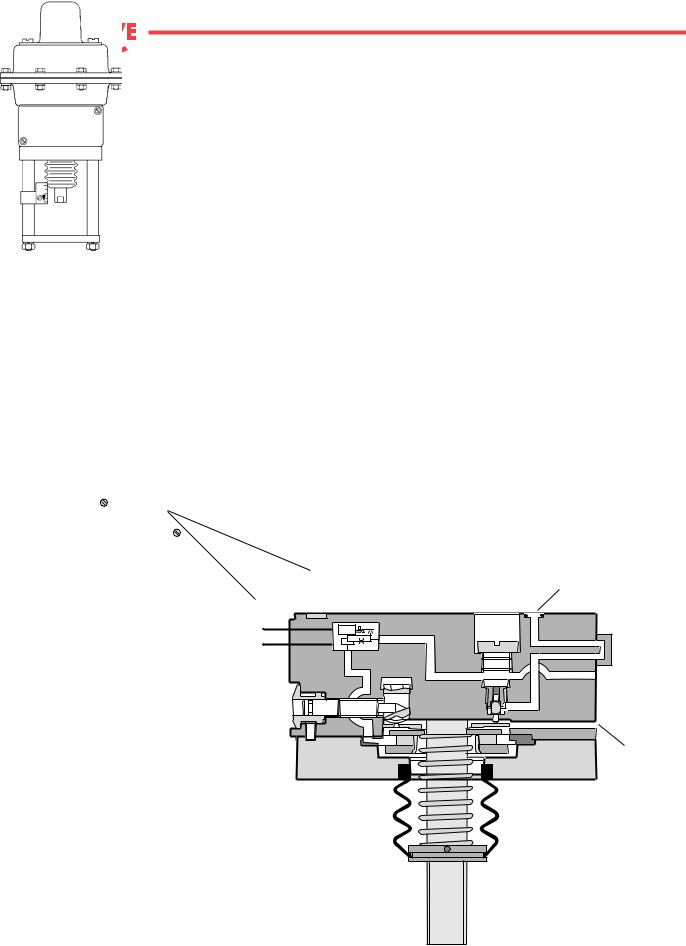
Supply output to actuator diaphragm
Supply input
1.4–4.2 bar (20–60 psi)
Range adjustment screw
(max. 3 turns)
Pilot plug
(see detail below)
Signal input |
Vent |
|
0.2–1.0 bar |
||
|
||
(3–15 psi) |
|
Double diaphragm |
Positioner spring |
Adjusting nut
Supply input 1.4 – 4.2 bar (20 – 60 psi)
Seat ring
Pilot valve
Supply to
actuator diaphragm
Vent
Balancing plate
Pilot plug
Fig. 2: P/P - Positioner
5
Flow Control Division
Kammer Control Valves
5.2I/P Actuator
The I/P transducer, which is an integral part of the actuator, converts the standard electric signal
(0/4 – 20 mA) into a standard pneumatic signal (0.2 – 1.0 bar) by means of a system of light weight moving parts. This form of signal conversion is extremely insensitive to shocks. The pneumatic signal is supplied to the integrated pneumatic positioner.
The pneumatic positioner works on the force balance principal, which ensures that the position of the actuator diaphragm is always directly proportional to the value of the instrument input signal pressure (see figs. 3 and 4). An increased signal to the double diaphragm assembly creates an unbalanced condition. The pilot valve then moves to cover the vent, increasing the positioner output pressure to the actuator diaphragm until the forces of the positioner spring and the double diaphragm are equal. The positioner output is then stabilized at an amount necessary to maintain the desired valve position.
To actuator
Signal
 Supply
Vent
Fig 3: I/P Positioner
6

Flow Control Division
Kammer Control Valves
Transducer
Signal 0/4 – 20 mA
Signal input 0.2–1.0 bar (3–15 psi)
Range adjustment screw (max. 3 turns)
Double diaphragm
Adjusting nut 
Seat ring
Balancing plate
Supply output to actuator diaphragm
Supply input
1.4–4.2 bar (20–60 psi)
Pilot plug
(see detail below)
Vent
Positioner spring
Supply input 1.4 – 4.2 bar (20 – 60 psi)
Pilot valve
Supply to
actuator diaphragm
Vent
Pilot plug
Fig. 4: I/P Positioner
7

Flow Control Division
Kammer Control Valves
2
1
Series 47 / 48 / 49 (without positioner)
2
1
3
4
Series 37 / 38 / 39
(with positioner)
Fig. 5
8
 Loading...