


 Loading...
GE Fanuc Automation
Computer Numerical Control Products
Super CAP M
Super CAP II M
Operator's Manual
GFZ-62154E/03 |
December 1995 |

GFL-001
Warnings, Cautions, and Notes as Used in this Publication
Warning
Warning notices are used in this publication to emphasize that hazardous voltages, currents, temperatures, or other conditions that could cause personal injury exist in this equipment or may be associated with its use.
In situations where inattention could cause either personal injury or damage to equipment, a Warning notice is used.
Caution
Caution notices are used where equipment might be damaged if care is not taken.
Note
Notes merely call attention to information that is especially significant to understanding and operating the equipment.
This document is based on information available at the time of its publication. While efforts have been made to be accurate, the information contained herein does not purport to cover all details or variations in hardware or software, nor to provide for every possible contingency in connection with installation, operation, or maintenance. Features may be described herein which are not present in all hardware and software systems. GE Fanuc Automation assumes no obligation of notice to holders of this document with respect to changes subsequently made.
GE Fanuc Automation makes no representation or warranty, expressed, implied, or statutory with respect to, and assumes no responsibility for the accuracy, completeness, sufficiency, or usefulness of the information contained herein. No warranties of merchantability or fitness for purpose shall apply.
©Copyright 1995 GE Fanuc Automation North America, Inc.
All Rights Reserved.

SAFETY PRECAUTIONS
When using a machine equipped with FANUC Super CAP M and FANUC Super CAP II M, the following safety precautions must be observed.
s±1

B±62154E/03
1 WARNING, CAUTION, AND NOTE
This manual includes safety precautions for protecting the user and preventing damege to the machine. Precautions are classified into Warning and Caution according to their bearing on safety. Also, supplementary information is described as a Note. Read the Warning, Caution, and Note thoroughly before attempting to use the machine.
Read this manual carefully, and store it in a safe place.
 WARNING
Applied when there is a danger of the user being injured or when there is a damege of both the user being injured and the equipment being dameged if the approved procedure is not observed.
 CAUTION
Applied when there is a danger of the equipment being dameged, if the approved procedure is not observed.
NOTE
The Note is used to indicate supplementary information other than Warning and Cation.
Read this manual carefully, and store it in a safe place.
s±2

B±62154E/03 |
SAFETY PRECAUTIONS |
|
|
|
|
|
|
|
2 |
GENERAL WARNINGS AND CAUTIONS |
|
|
|
|
|
|
|
 WARNING
1Before attempting to use a conversational function (such as the creation/editing/run of machining programs, machining simulation, and the measurement of tool compensation), close the doors of the machine, and apply any other safety measures deemed necessary.
Failure to apply the necessary safety precautions may result in the serious injury, or even death, of the user or bystanders.
2.Before proceeding to the next step of a procedure, check the display on the screen carefully to ensure that the data has been entered exactly as intended.
If the machine is operated with incorrect data, the tool may collide with the machine and/or workpiece, possibly causing damage to the tool and/or machine, or even injury to the user or bystanders.
3.When the tool compensation function is being used before starting the machine, check the direction and amount of compensation so that the tool will not collide with the workpiece or machine.
If the tool collides with the machine and/or workpiece, the tool and/or machine may be damaged, plus there is the danger of injury to the user or bystanders.
4.After you create a machining program using a conversational function, do not operate the machine using that program immediately. Instead, perform a machining simulation to ensure that the tool path and machining operation are satisfactory and that the tool will not collide with the workpiece or machine (including the jig).
If the tool collides with the machine and/or workpiece, the tool and/or machine may be damaged, plus there is the danger of injury to the user or bystanders.
5.After you convert a machining program, created using a conversational function, to NC program format, do not operate the machine using that program immediately. Instead, confirm every step of the NC program, and ensure that the tool path and machining operation are satisfactory and that the tool will not collide with the workpiece or machine (including the jig). Before starting production machining, operate the machine without a workpiece mounted to ensure that the tool will not collide with the workpiece (were it to be mounted) or the machine (including the jig).
If the tool collides with the machine and/or workpiece, the tool and/or machine may be damaged, plus there is the danger of injury to the user or bystanders.
6.Before starting to create a machining program using a conversational function, first check that all required data within the tool file, cutting condition file, and pre±tool list, and all parameters required for the conversational function, is set correctly.
If any of the required data is not set correctly, the cutting conditions will not be set correctly, possibly resulting in damage to the tool, or even injury to the user or bystanders.
s±3

B±62154E/03
 WARNING
7.When you operate the machine using a machining program created using a conversational function or a machining program generated by converting another machining program to NC program format, be particularly careful to use the correct tool compensation data.
If the machine is used with incorrect data, the tool may collide with the machine and/or workpiece, possibly causing damage to the tool and/or machine, or even injury to the user or bystanders.The method of measuring the tool compensation amount varies depending on the machine tool builder. Before starting measurement, therefore, users must read and become totally familiar with the relevant manual(s), supplied by the machine tool builder.
8.After pressing the power ON button, do not touch any key on the keyboard until the screen display appears. Some keys are allocated to maintenance or other special operations. Pressing any of these keys may result in the machine not behaving as expected.
s±4

B±62154E/03 |
Table of contents |
SAFETY PRECAUTIONS . . . . . . . . . . . . . . . . . . . . . . . . . . . . . . . . . . . . . . . . . |
s±1 |
1. WARNING, CAUTION, AND NOTE . . . . . . . . . . . . . . . . . . . . . . . . . . . . . . . . . . . . . . . s±2 2. GENERAL WARNINGS AND CAUTIONS . . . . . . . . . . . . . . . . . . . . . . . . . . . . . . . . . s±3
I. OVERVIEW . . . . . . . . |
. . . . . . . |
. . . . . . . . . . |
. . . . . . . . . . . . . . . . . |
. . . . . . . . . |
1 |
||
1. MANUAL OVERVIEW . . . . . . . |
. . . . . . . . . . . |
. . . . . . . . . . . . . . . . . . . . |
. . . . . . . . . . . . |
3 |
|||
2. SYMBOLS . . . . . . . . . |
. . . . . . . . |
. . . . . . . . . . . |
. . . . . . . . . . . . . . . . . . . . |
. . . . . . . . . . . . |
4 |
||
3. GENERAL PROCEDURE FROM PROGRAMMING TO EXECUTION . . . . . . . . . |
5 |
||||||
4. OPERATING PRECAUTIONS |
. . . . . . . . . . . |
. . . . . . . . . . . . . . . . . . . . |
. . . . . . . . . . . . |
7 |
|||
.043 "3" 3 |
|
||||||
2 |
"$+(1/4.% %*3*.( |
3 |
|
||||
3 |
//, ''2&3 4-#&1 |
3 |
|
||||
II. FANUC Super CAP M FANUC Super CAP II M . . . . . . . . . . |
. . . . . . . . . |
9 |
|||||
1. OVERVIEW OF FANUC Super CAP M, FANUC Super CAP II M . |
. . . . . . . . . . . . |
11 |
|||||
|
/1+ 5&15*&6 3 |
|
|||||
2 1&"3*.( " "$)*.*.( 1/(1"- |
"2*$ &.4 ! |
|
2 |
||||
3 %*3*.( " "$)*.*.( 1/(1"- |
"2*$ &.4 ! |
|
2 |
||||
|
3 |
/%*'7 '4.$3*/. |
|
3 |
3 |
||
|
3 2 |
.2&13 '4.$3*/. |
|
|
3 |
32 |
|
|
3 3 |
/5& '4.$3*/. |
|
3 |
3 |
||
|
3 |
/07 '4.$3*/. |
|
3 |
3 |
||
|
3 |
&,&3& '4.$3*/. |
3 |
|
|||
|
"$)*.*.( 1/(1"- 03*-*8"3*/. "2*$ &.4 2! |
3 |
|||||
|
|
03*-", 01/$&22 &%*3*.( '4.$3*/. "43/-"3*$ ",3&1"3*/. |
|
||||
|
2 |
03*-", 01/$&22 &%*3*.( ",(/1*3)- |
|
||||
|
3 |
03*-", 01/$&22 &%*3*.( '4.$3*/. -".4", ",3&1"3*/. |
|
||||
|
"$)*.*.( 1/(1"- )&$+ "2*$ &.4 3! |
|
|||||
|
|
//, 0"3) %1"6*.( 3 |
|
||||
|
2 |
.*-"3&% 2*-4,"3*/. 3 |
|
||||
|
3 |
"$)*.*.( 3*-& %*20,"7 3 |
63 |
||||
|
|
"$+(1/4.% %1"6*.( /03*/.", 3 |
6 |
||||
|
|
/3&2 /. %1"6*.( 3 |
|
||||
6 |
3"3&-&.3 43043 4.$3*/. "2*$ &.4 ! |
|
|||||
|
6 |
23"3&-&.3 /43043 '4.$3*/. 3 |
|
||||
|
6 2 |
,"1-2 1"*2&% %41*.( 23"3&-&.3 /43043 |
|
3 |
|||
|
6 3 |
&33*.(2 1&,"3&% 3/ 3)& 1&"%&1 04.$) *.3&1'"$& |
|
||||
|
/.5&12"3*/.", "3" &33*.( ".% &'&1&.$& "2*$ &.4 ! |
|
|||||
|
|
"3" 3 |
6 |
||||
|
2 |
.*3*", 5",4& '*,& 3 |
|
||||
|
3 |
//, ,*23 3 |
|
||||
|
|
1& 3//, ,*23 3 |
|
||||
|
|
//, '*,& 3 |
|
||||
i

Table of contents |
B±62154E/03 |
. .6 |
Tool directory . . . . . . . . . . . . . . . . . . . . . . . . . . . . . . . . . . . . . . . . . . . . . . . . . . . |
3 . . . . . . . . . . . . . . . . . |
3 |
. . |
ategorized tool directories . . . . . . . . . . . . . . . . . . . . . . . . . . . . . . . . . . . . . . . |
. . . . . . . . . . . . 3 . . . . . |
|
. . |
utting condition file . . . . . . . . . . . . . . . . . . . . . . . . . . . . . . . . . . . . . . . . . . . . . |
. . . . . . 3 . . . . . . . . . . . |
6 |
. Other unctions . . . . . . . . . . . . . . . . . . . . . . . . . . . . . . . . . . . . . . . . . . . . . . . . . . . 3 . . . . . . . . . . . . . . .
. . |
Program list . . . . . . . . . . . . . . . . . . . . . . . . . . . . . . . . . . . . . . . . . . . . . . . . . . . |
3 . . . . . . . . . . . . . . . . . . . |
|
. .2 |
rithmetic functions . . . . . . . . . . . . . . . . . . . . . . . . . . . . . . . . . . . . . . . . . . . |
. . . . . . . . 3 . . . . . . . . . . . |
|
. .3 |
mbedding tool management numbers . . . . . . . . . . . . . . . . . . . . . . . . . . . |
. . . . . . . . . . . . . . . . . . . |
2 |
2. MACHINING MENU DESCRIPTIONS . . . . . . . . . . . . . . . . . . . . . . . . . . . . . . . . . . . . . 93
2. |
Types of Machining Menus . . . . . . . . . . . . . . . . . . . . . . . . . . . . . . . . . . . . . . . . . . . |
. . . . . . . . 3 . . . . . |
3 |
2.2 |
Initial Setting, etc. . . . . . . . . . . . . . . . . . . . . . . . . . . . . . . . . . . . . . . . . . . . . . . . . . . . |
3 . . . . . . . . . . . . . |
|
2.2. Initial setting ZI . . . . . . . . . . . . . . . . . . . . . . . . . . . . . . . . . . . . . . . . . . . . . . . . . . . 3 . . . . . . . . . . . 2.2.2 nd of program ZI 2 . . . . . . . . . . . . . . . . . . . . . . . . . . . . . . . . . . . . . . . . . . . . . . . . . . . 3 . . . . . . . . . . 2.2.3 axis rotation ZI 3 . . . . . . . . . . . . . . . . . . . . . . . . . . . . . . . . . . . . . . . . . . . . . . . . . . . 3 . . . . . . . . . .
2.2. N language preparation ZI . . . . . . . . . . . . . . . . . . . . . . . . . . . . . . . . . . . . . . . . . . . . . . . . . . . 3 .
2.2. ll copy Random ZI . . . . . . . . . . . . . . . . . . . . . . . . . . . . . . . . . . . . . . . . . . . . . . . . . . . 3 . . . . . . . 3 2.2.6 ll copy Pattern ZI 6 . . . . . . . . . . . . . . . . . . . . . . . . . . . . . . . . . . . . . . . . . . . . . . . . . . . 3 . . . . . . . .
2.2. Group copy Random ZI . . . . . . . . . . . . . . . . . . . . . . . . . . . . . . . . . . . . . . . . . . . . . . . . . . . 3 . . . .
2.2. Group copy Pattern ZI . . . . . . . . . . . . . . . . . . . . . . . . . . . . . . . . . . . . . . . . . . . . . . . . . . . 3 . . . . .
2.2. Group copy Turn ZI . . . . . . . . . . . . . . . . . . . . . . . . . . . . . . . . . . . . . . . . . . . . . . . . . . . 3 . . . . . . .
2.3 Hole Machining . . . . . . . . . . . . . . . . . . . . . . . . . . . . . . . . . . . . . . . . . . . . . . . . . . . 3 . . . . . . . . . . . . . . . 2
2.3. rilling ZH . . . . . . . . . . . . . . . . . . . . . . . . . . . . . . . . . . . . . . . . . . . . . . . . . . . 3 . . . . . . . . . . . . . . . . 3 2.3.2 Peck drilling ZH 2 . . . . . . . . . . . . . . . . . . . . . . . . . . . . . . . . . . . . . . . . . . . . . . . . . . . 3 . . . . . . . . . . . .
2.3.3 oring ZH 3 . . . . . . . . . . . . . . . . . . . . . . . . . . . . . . . . . . . . . . . . . . . . . . . . . . . 3 . . . . . . . . . . . . . . . . . 2 2.3. ine boring ZH . . . . . . . . . . . . . . . . . . . . . . . . . . . . . . . . . . . . . . . . . . . . . . . . . . . 3 . . . . . . . . . . . . 2 2.3. ackboring ZH . . . . . . . . . . . . . . . . . . . . . . . . . . . . . . . . . . . . . . . . . . . . . . . . . . . 3 . . . . . . . . . . . . . 23 2.3.6 Tapping ZH 6 . . . . . . . . . . . . . . . . . . . . . . . . . . . . . . . . . . . . . . . . . . . . . . . . . . . 3 . . . . . . . . . . . . . . . . 2 2.3. Reaming ZH . . . . . . . . . . . . . . . . . . . . . . . . . . . . . . . . . . . . . . . . . . . . . . . . . . . 3 . . . . . . . . . . . . . . . 2 2.3. Spot facing ircle cut ZH . . . . . . . . . . . . . . . . . . . . . . . . . . . . . . . . . . . . . . . . . . . . . . . . . . . 3 . . 2
2. Hole Pattern . . . . . . . . . . . . . . . . . . . . . . . . . . . . . . . . . . . . . . . . . . . . . . . . . . . 3 . . . . . . . . . . . . . . . . . . 3
2. . Group of points ZL . . . . . . . . . . . . . . . . . . . . . . . . . . . . . . . . . . . . . . . . . . . . . . . . . . . 3 . . . . . . . . . 32 2. .2 Line Same space ZL 2 . . . . . . . . . . . . . . . . . . . . . . . . . . . . . . . . . . . . . . . . . . . . . . . . . . . 3 . . . . . . . 33 2. .3 Line iffer SP ZL 3 . . . . . . . . . . . . . . . . . . . . . . . . . . . . . . . . . . . . . . . . . . . . . . . . . . . 3 . . . . . . . 3 2. . Grid ZL . . . . . . . . . . . . . . . . . . . . . . . . . . . . . . . . . . . . . . . . . . . . . . . . . . . 3 . . . . . . . . . . . . . . . . . . . 36 2. . Parallelogram ZL . . . . . . . . . . . . . . . . . . . . . . . . . . . . . . . . . . . . . . . . . . . . . . . . . . . 3 . . . . . . . . . . . 3 2. .6 olt hole circle ZL 6 . . . . . . . . . . . . . . . . . . . . . . . . . . . . . . . . . . . . . . . . . . . . . . . . . . . 3 . . . . . . . . . . 3 2. . rc Same space ZL . . . . . . . . . . . . . . . . . . . . . . . . . . . . . . . . . . . . . . . . . . . . . . . . . . . 3 . . . . . . . . 3 2. . rc iffer space ZL . . . . . . . . . . . . . . . . . . . . . . . . . . . . . . . . . . . . . . . . . . . . . . . . . . . 3 . . . . . . .
2. . opy Random ZL . . . . . . . . . . . . . . . . . . . . . . . . . . . . . . . . . . . . . . . . . . . . . . . . . . . 3 . . . . . . . . .
2. . opy Pattern ZL . . . . . . . . . . . . . . . . . . . . . . . . . . . . . . . . . . . . . . . . . . . . . . . . . . . 3 . . . . . . . . . . 2
2. acing . . . . . . . . . . . . . . . . . . . . . . . . . . . . . . . . . . . . . . . . . . . . . . . . . . . 3 . . . . . . . . . . . . . . . . . . . . . . . .
2. . acing prepare Z . . . . . . . . . . . . . . . . . . . . . . . . . . . . . . . . . . . . . . . . . . . . . . . . . . . 3 . . . . . . . . . .
2. .2 Square uni-dir Z 2 . . . . . . . . . . . . . . . . . . . . . . . . . . . . . . . . . . . . . . . . . . . . . . . . . . . 3 . . . . . . . .
2. .3 Square bi-dir Z 3 . . . . . . . . . . . . . . . . . . . . . . . . . . . . . . . . . . . . . . . . . . . . . . . . . . . 3 . . . . . . . . . . 2 2. . ircle uni-dir Z . . . . . . . . . . . . . . . . . . . . . . . . . . . . . . . . . . . . . . . . . . . . . . . . . . . 3 . . . . . . . . . .
2. . ircle bi-dir Z . . . . . . . . . . . . . . . . . . . . . . . . . . . . . . . . . . . . . . . . . . . . . . . . . . . 3 . . . . . . . . . . . .
2. .6 Square Ring Z 6 . . . . . . . . . . . . . . . . . . . . . . . . . . . . . . . . . . . . . . . . . . . . . . . . . . . 3 . . . . . . . . . . . 6 2. . ircular surface Ring Z . . . . . . . . . . . . . . . . . . . . . . . . . . . . . . . . . . . . . . . . . . . . . . . . . . . 3 . . .
2. . opy Random Z . . . . . . . . . . . . . . . . . . . . . . . . . . . . . . . . . . . . . . . . . . . . . . . . . . . 3 . . . . . . . . .
2. . opy Pattern Z . . . . . . . . . . . . . . . . . . . . . . . . . . . . . . . . . . . . . . . . . . . . . . . . . . . 3 . . . . . . . . . .
2.6 Side utting . . . . . . . . . . . . . . . . . . . . . . . . . . . . . . . . . . . . . . . . . . . . . . . . . . . 3 . . . . . . . . . . . . . . . . . .
2.6. Side preparation ZS . . . . . . . . . . . . . . . . . . . . . . . . . . . . . . . . . . . . . . . . . . . . . . . . . . . 3 . . . . . . . . 6 2.6.2 Square outside ZS 2 . . . . . . . . . . . . . . . . . . . . . . . . . . . . . . . . . . . . . . . . . . . . . . . . . . . 3 . . . . . . . . . .
2.6.3 Square inside ZS 3 . . . . . . . . . . . . . . . . . . . . . . . . . . . . . . . . . . . . . . . . . . . . . . . . . . . 3 . . . . . . . . . . .
2.6. ircle outside cutting ZS . . . . . . . . . . . . . . . . . . . . . . . . . . . . . . . . . . . . . . . . . . . . . . . . . . . 3 . . . .
ii

B±62154E/03 |
o on n |
|
|
|
2 6 |
Circle inside ZS |
|
|
3 |
2 |
||
|
2 6 6 |
Track outside ZS 6 |
|
|
3 |
3 |
||
|
2 6 |
Track inside ZS |
|
|
3 |
|
||
|
2 6 |
ne side ZS |
|
3 |
|
|||
|
2 6 |
Contour prepare ZS |
|
3 |
|
|||
|
2 6 |
Copy Random ZS |
|
|
3 |
|
||
|
2 6 |
Copy attern ZS |
|
|
3 |
|
||
2 |
ocketing 3 |
|||||||
|
2 |
ocketting prep Z 3 |
|
|||||
|
2 2 |
Square pocket Z 2 |
3 |
6 |
||||
|
2 3 |
Circle pocket Z 3 |
3 |
2 |
||||
|
2 |
Track pocket Z |
3 |
2 2 |
||||
|
2 |
olygonal pocket Z 3 |
2 3 |
|||||
|
2 6 |
olygonal pokt with radius Z 6 |
2 |
|||||
|
2 |
Grooving Z 3 |
2 |
|||||
|
2 |
Cont pocket prep Z 3 |
2 |
|||||
|
2 |
Contour grooving preparation Z |
|
2 |
||||
|
2 |
Copy random Z |
3 |
2 |
||||
|
2 |
Copy pattern Z |
3 |
2 |
||||
2 |
C Language 3 2 |
|||||||
|
2 |
ositioning Z 3 |
22 |
|||||
|
2 2 |
Line Z 2 3 |
22 |
|||||
|
2 3 |
rc Z 3 3 |
222 |
|||||
|
2 |
rogram stop end Z 3 |
223 |
|||||
|
2 |
Feed rate Z 3 |
22 |
|||||
|
2 6 |
Coolant Z 6 |
3 |
22 |
||||
|
2 |
Spindle Z |
3 |
226 |
||||
|
2 |
C language Z |
3 |
22 |
||||
2 |
2 + 2 Convex Cut 3 22 |
|||||||
|
2 |
2 + 2 Convex cut prep ZV 3 |
22 |
|||||
|
2 2 |
CVX QU D R ZV 2 |
3 |
233 |
||||
|
2 3 |
CVX hemisphere ZV 3 3 |
2 |
|||||
|
2 |
CVX half CYL L ZV 3 |
2 |
|||||
|
2 |
CVX HLF CYL ring ZV 3 |
2 3 |
|||||
|
2 6 |
Copy random ZV 6 |
3 |
2 3 |
||||
|
2 |
Copy pattern ZV |
3 |
2 3 |
||||
2 2 + 2 Concave Cut |
3 2 |
|||||||
|
2 |
2 + 2 Concave cut prep ZC 3 |
2 |
|||||
|
2 2 |
CCV QU D R ZC 2 |
3 |
2 |
||||
|
2 3 |
CCV hemisphere ZC 3 3 |
2 6 |
|||||
|
2 |
CCV half CYL L ZC 3 |
2 |
|||||
|
2 |
CCV HLF CYL ring ZC 3 |
2 |
|||||
|
2 6 |
Copy random ZC 6 |
3 |
2 |
||||
|
2 |
Copy pattern ZC |
3 |
2 |
||||
2 Contour Cutting rogramming 3 2
2 |
Contour side cutting 3 |
2 |
2 2 |
mproved approach and escape 3 |
2 |
2 3 |
Contour pocket cutting 3 |
2 3 |
2 |
Contour grooving 3 |
2 3 |
2 |
Calculating a contour figure 3 |
2 6 |
2 6 |
Contour repetition function option |
3 |
2 |
Contour editing 3 |
32 |
2 |
Contour alarms 3 |
322 |
2 |
Restrictions and rules on calculating the contour |
32 |
iii

Table of contents |
B±62154E/03 |
2.12 U-axis Machining Option . . . . . . . . . . . . . . . . . . . . . . . . . . . . . . . . . . . . . . . . . . . . . . . . . . . 2 . . . . 332
2.12.1 U-axis machining menu items . . . . . . . . . . . . . . . . . . . . . . . . . . . . . . . . . . . . . . . . . . . . . . . . . . . 2 . . 332 2.12.2 reating and editing a U-axis machining program . . . . . . . . . . . . . . . . . . . . . . . . . . . . . . . . . . . 334 2.12.3 hecking a U-axis machining program . . . . . . . . . . . . . . . . . . . . . . . . . . . . . . . . . . . . . . . . . . . . . 366 2.12.4 U-axis machining program N statement output . . . . . . . . . . . . . . . . . . . . . . . . . . . . . . . . . . . . 368 2.12.5 Tool file for U-axis machining . . . . . . . . . . . . . . . . . . . . . . . . . . . . . . . . . . . . . . . . . . . . . . . . . . . 2 . . 371 2.12.6 Restrictions imposed on U-axis machining . . . . . . . . . . . . . . . . . . . . . . . . . . . . . . . . . . . . . . . . . . 374
2.13 Setup Guidance unction . . . . . . . . . . . . . . . . . . . . . . . . . . . . . . . . . . . . . . . . . . . . . . . . . . . 2 . . . . . . 377
2.13.1 Outline . . . . . . . . . . . . . . . . . . . . . . . . . . . . . . . . . . . . . . . . . . . . . . . . . . . 2 . . . . . . . . . . . . . . . . . . . . . . . 377
2.13.2 Operation . . . . . . . . . . . . . . . . . . . . . . . . . . . . . . . . . . . . . . . . . . . . . . . . . . . 2 . . . . . . . . . . . . . . . . . . . . . 378
2.13.3 Appendix . . . . . . . . . . . . . . . . . . . . . . . . . . . . . . . . . . . . . . . . . . . . . . . . . . . 2 . . . . . . . . . . . . . . . . . . . . . 393
2.14 irect Operation of .A.P. Program . . . . . . . . . . . . . . . . . . . . . . . . . . . . . . . . . . . . . . . . . . . . . . . . . 396
2.14.1 Screen configuration . . . . . . . . . . . . . . . . . . . . . . . . . . . . . . . . . . . . . . . . . . . . . . . . . . . 2 . . . . . . . . . . . 396 2.14.2 Program Re-Start . . . . . . . . . . . . . . . . . . . . . . . . . . . . . . . . . . . . . . . . . . . . . . . . . . . 2 . . . . . . . . . . . . . 407 2.14.3 PARAM T R . . . . . . . . . . . . . . . . . . . . . . . . . . . . . . . . . . . . . . . . . . . . . . . . . . . 2 . . . . . . . . . . . . . . . . . 411
2.15 efining a Pre-Hole for Pocketing/Grooving . . . . . . . . . . . . . . . . . . . . . . . . . . . . . . . . . . . . . . . . 413
2.15.1 General . . . . . . . . . . . . . . . . . . . . . . . . . . . . . . . . . . . . . . . . . . . . . . . . . . . 2 . . . . . . . . . . . . . . . . . . . . . . . 413
2.15.2 diting Macro . . . . . . . . . . . . . . . . . . . . . . . . . . . . . . . . . . . . . . . . . . . . . . . . . . . 2 . . . . . . . . . . . . . . . . . 413
2.15.3 Parameter, Machining condition file . . . . . . . . . . . . . . . . . . . . . . . . . . . . . . . . . . . . . . . . . . . . . . . . . 416
2.15.4 Appendix . . . . . . . . . . . . . . . . . . . . . . . . . . . . . . . . . . . . . . . . . . . . . . . . . . . 2 . . . . . . . . . . . . . . . . . . . . . 416
2.16 anned ycle Output for Hole Machining . . . . . . . . . . . . . . . . . . . . . . . . . . . . . . . . . . . . . . . . . . . 417
2.16.1 General . . . . . . . . . . . . . . . . . . . . . . . . . . . . . . . . . . . . . . . . . . . . . . . . . . . 2 . . . . . . . . . . . . . . . . . . . . . . . 417 2.16.2 Applicable machining . . . . . . . . . . . . . . . . . . . . . . . . . . . . . . . . . . . . . . . . . . . . . . . . . . . 2 . . . . . . . . . . 417 2.16.3 Others . . . . . . . . . . . . . . . . . . . . . . . . . . . . . . . . . . . . . . . . . . . . . . . . . . . 2 . . . . . . . . . . . . . . . . . . . . . . . . 418
III. NEW FEATURES OF SUPER CAP II M . . . . . . . . . . . . . . . . . . . . . . . . . 421
1. NEW FEATURES OF SUPER CAP II M . . . . . . . . . . . . . . . . . . . . . . . . . . . . . . . . . . . 423
1.1 Improved onversational Programming Screen . . . . . . . . . . . . . . . . . . . . . . . . . . . . . . . . . . . . . . 423 1.2 Improved Animated Simulation unction . . . . . . . . . . . . . . . . . . . . . . . . . . . . . . . . . . . . . . . . . . . 424
1.2.1 ross-Sectional View . . . . . . . . . . . . . . . . . . . . . . . . . . . . . . . . . . . . . . . . . . . . . . . . . . . 2 . . . . . . . . . . 424
1.2.2 Plan View . . . . . . . . . . . . . . . . . . . . . . . . . . . . . . . . . . . . . . . . . . . . . . . . . . . 2 . . . . . . . . . . . . . . . . . . . . . 424
1.3 |
hanging The Screen isplay olors . . . . . . . . . . . . . . . . . . . . . . . . . . . . . . . . . . . . . . . . . |
. . . . . . |
425 |
|
|
1.3.1 |
Setting the isplay olors . . . . . . . . . . . . . . . . . . . . . . . . . . . . . . . . . . . . . . . . . . . . . . . . . . . |
2 . . . . . . |
425 |
|
1.3.2 |
Storing and alling isplay olor ata . . . . . . . . . . . . . . . . . . . . . . . . . . . . . . . . . . . . . . . . |
. . . . . . |
426 |
1.4 |
ontour igure Window unction . . . . . . . . . . . . . . . . . . . . . . . . . . . . . . . . . . . . . . . . . . . . . |
. . . . . |
427 |
|
IV. PARAMETERS AND ALARMS . . . . . . . . . . . . . . . . . . |
. . . . . . . . . . . . . . . |
429 |
|
1. PARAMETERS . . . . . . . . . . . . . . . . . . . . . . . . . . . . . . . . . . . . . . |
. . . . . . . . . . . . . . . . . . |
431 |
|
1.1 |
Parameters Related to Graphic isplay . . . . . . . . . . . . . . . . . . . . . . . . |
. . . . . . . . . . . . . . . . . . . . . |
431 |
1.2 |
Macro xecutor . . . . . . . . . . . . . . . . . . . . . . . . . . . . . . . . . . . . . . . . . . . . . |
. . . . . . 2 . . . . . . . . . . . . . |
. . 433 |
1.3 |
AP ontrol . . . . . . . . . . . . . . . . . . . . . . . . . . . . . . . . . . . . . . . . . . . . . . . . |
. . . 2 . . . . . . . . . . . . . . . . . |
. 434 |
1.4 |
AP ile . . . . . . . . . . . . . . . . . . . . . . . . . . . . . . . . . . . . . . . . . . . . . . . . . . . |
2 . . . . . . . . . . . . . . . . . . . . |
. 440 |
1.5 |
Menu ontrol . . . . . . . . . . . . . . . . . . . . . . . . . . . . . . . . . . . . . . . . . . . . . . . |
. . . . 2 . . . . . . . . . . . . . . . . |
. 444 |
1.6 |
ontour . . . . . . . . . . . . . . . . . . . . . . . . . . . . . . . . . . . . . . . . . . . . . . . . . . . |
2 . . . . . . . . . . . . . . . . . . . . . |
. 447 |
2. ALARMS . . . . . . . . . . . . . . . . . . . . . . . . . . . . . . . . . . . . . . . . . . . . . |
. . . . . . . . . . . . . . . . . |
453 |
|
2.1 |
Alarms Related to Machining Other than ontouring . . . . . . . . . . . |
. . . . . . . . . . . . . . . . . . . . . |
453 |
2.2 |
Alarms Related to ontouring . . . . . . . . . . . . . . . . . . . . . . . . . . . . . . . . |
. . . . . . . . . . . . . . . . . . . 2 . |
. 454 |
iv
I. OVERVIEW

B±62154E/03 |
1. MANUAL OVERVIEW |
|
|
|
|
1. MANUAL OVERVIEW
This manual describes the functions of FANUC Super CAP M and FANUC Super CAP II M.
For the other functions, refer to the operator's manual describing the NC of the FANUC Series 16/18.
The specifications and use of FANUC Super CAP M and FANUC Super CAP II M depend on the specifications of the machine operator's manual. Be sure to refer to the manual written by the machine tool builder.
The functions of a CNC machine tool system are determined not only by the CNC but also by the combination of the machine, power magnetics circuit, servo system, CNC, operator's panel, and other units.
It is impossible to explain the functions, programming, and operations for each of the combinations.
This manual describes the conversational input functions of the CNC. For the functions of each CNC machine tool, refer to the manual written by the machine tool builder.
FANUC Super CAP M and FANUC Super CAP II M are compatible with the following models. These model names are abbreviated in this manual.
Product name |
Abbreviation |
|
|
FANUC Series 16±MA |
16±MA |
|
|
FANUC Series 18±MA |
18±MA |
|
|
FANUC Series 16±MB |
16±MB |
|
|
FANUC Series 18±MB |
18±MB |
|
|
FANUC Series 16±MC |
16±MC |
|
|
FANUC Series 18±MC |
18±MC |
|
|
FANUC Super CAP M and FANUC Super CAP II M consist of custom macro programs. In addition to standard custom macro instructions, many conversational macro instructions (for example, a macro instruction for drawing) are provided.
FANUC separately provides the FANUC standard program, a conversational automatic programming function created from custom macro programs by FANUC. (The FANUC standard program can be purchased as a ROM module.) By adding to and modifying the custom macro program of the FANUC standard program, and each machine tool builder can create his own conversational automatic programming function incorporating the machining know±how.
This manual describes the conversational automatic programming function provided by FANUC. The specifications depend on each machine tool builder. Ask the machine tool builder beforehand whether they have added to or modified the standard function.
The description in the manual written by the machine tool builder has priority over that in this manual.
<About Super CAP II M>
Super CAP II M is a development of Super CAP M, featuring the following new functions:
(1)Neutral background color for the display screen, and 3±D frames for the windows and soft keys
(2)Finer and faster machining simulation based on a solid model
(3)Cross±sectional display of a product based on a solid model
(4)Selectable screen display colors, with the storage of up to four color schemes
(5)Improved visual interface for contour machining, in which the contour figure is displayed during contour programming
All other functions such as screen displays, key operations, and machining functions are the same as those of super CAP M.
Moreover, machining programs, tool data, and conversational function parameters created with Super CAP M can also be used with Super CAP II M.
For details of the new functions, see Part III, ºNew Features of Super CAP II M.º
This manual gives a lot of information to the reader. It, however, cannot detail all the operations that must not be attempted or cannot be executed.
The system can execute only functions that are explicitly said to be possible in this manual.
Notes in this manual describe particular conditions in minute detail. The note may include terms which have not yet been explained. If such terms are found, skip the note and read the remaining part of the manual. Then, read the note again.
± 3 ±

B±62154E/03
2. SYMBOLS
This manual indicates key operations by using the following symbols:
(1)An MDI key (on which alphanumeric characters or symbols are marked) is enclosed in a pair of angle brackets (<>).
Example <PROG> <OFFSET>
(2)A soft key (shown at the bottom of the screen) is enclosed in a pair of square brackets ([]).
Example [C.A.P.] [EXEC]
(3)Cursor keys are represented as follows:
↑↓ ← →
(4)Page keys are represented as follows'
± 4 ±
B±62154E/03 |
1. MANUAL OVERVIEW |
|
|
|
|
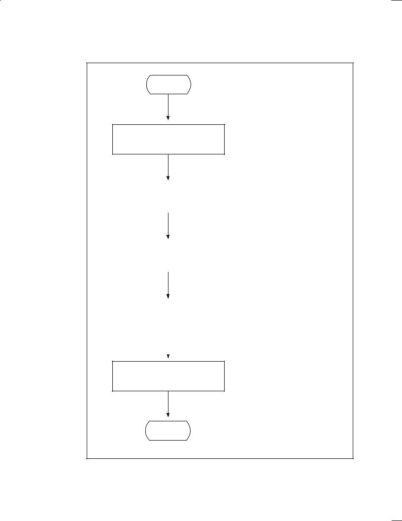
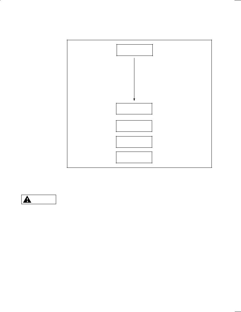
3. GENERAL PROCEDURE FROM PROGRAMMING TO EXECUTION
The flowchart below shows a general procedure from programming to machining with the conversational automatic programming function.
Start
Creation and editing of a program by the conversational automatic programming function
See Sections 1.1, 1.2, 1.3, and 1.7 of Chapter II. (EDIT and back ground edit modes)
Optimization of the machining program |
See Section 1.4 of Chapter II. (EDIT |
|
and back ground edit modes) |
|
|
|
Program check by drawing |
See Section 1.5 of Chapter II. |
|
|
|
|
(MEMORY mode) |
|
|
|
|
|
|
|
|
|
|
|
|
|
NC program conversion |
See Section 1.6 of Chapter II. |
|
|
|
|
(MEMORY mode) |
|
|
|
|
|
|
|
|
|
|
|
|
Machining |
(MEMORY mode) |
End
± 5 ±

B±62154E/03
WARNING
WARNING
Before starting to create a machining program using a conversational function, first check that all required data within the tool file, cutting condition file, and pre±tool list, is set correctly.
If any of the required data is not set correctly, the cutting conditions will not be set correctly, possibly causing damage to the tool, or even injury to the user or bystanders.
Before proceeding to the next step of a procedure, carefully check the contents of the screen display to ensure that the data has been entered exactly as intended.
If the machine is operated with incorrect data, the tool may collide with the machine and/or workpiece, possibly causing damage to the tool and/or machine, or even injury to the user or bystanders.
± 6 ±

B±62154E/03 |
1. MANUAL OVERVIEW |
|
|
|
|
4.OPERATING PRECAUTIONS
4.1Input Data
(1)On the conversational data input screen, enter lengths and coordinates in millimeters (metric mode) or inches (inch mode).
(2)Usually, entries with an asterisk (*) need not be specified in the FANUC standard macro. Specify them only when required.
(3)This system is not applicable to machines operating in IS±C (0.1 um) mode.
4.2Background Editing
The following operations cannot be executed during background editing:
(1)Drawing of the machining profile, animated simulation
(Can be executed if the optional background drawing function is provided.)
(2)NC statement output function
(3)Setting and changing the tool offset value in the list of tools to be used
(4)Setting and changing a tool file
4.3Tool Offset Number
When contour side cutting or contour pocket cutting is carried out, the offset data in parameter No. 9404 is automatically overwritten. The offset number and offset data cannot be used.
When 0 is set in that parameter, the following offset data is used instead.
(1)Data No. 32 when 32 sets of tool offset are specified
(2)Data No. 64 when 64 sets of tool offset are specified
(3)Data No. 99 when 99 sets of tool offset are specified
(4)Data No. 200 when 200 sets of tool offset are specified
± 7 ±

II.FANUC Super CAP M FANUC Super CAP II M
B±62154E/03 |
FANUC Super CAP II M |
|
|
|
|
1. OVERVIEW OF FANUC Super CAP M, FANUC Super CAP II M
1.1 Work Overview
Conversational automatic programming is a technique for creating machining programs by entering the dimensions of drawings and other data on the CRT screen.
To use the conversational automatic programming function, press the <PROG> key on the MDI panel, then press the soft key [C.A.P.]. (The [C.A.P.] key is displayed on the screen only when the NC unit is in the EDIT or BG±EDIT mode.)
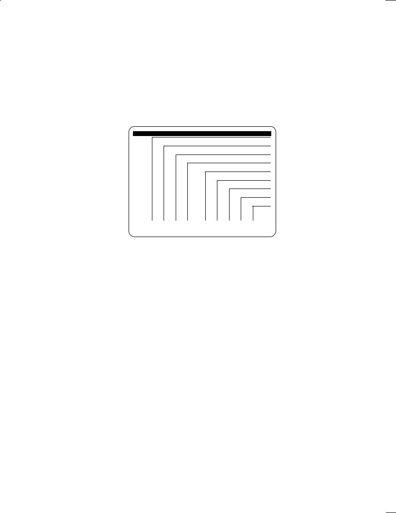
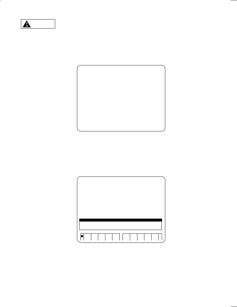
The menu screen shown below (basic menu screen) is displayed. Conversational programming begins with the basic menu screen.
SUPER C.A.P. M
PROGRAM MAKE OR EDIT
OPTIMUM PROGRAM
PROGRAM CHECK
CONVERT NC FORMAT
MEM |
MEM |
C.A.P. DATA |
MODE |
MODE |
|
|
|
|
1 |
2 |
3 |
4 |
|
5 |
6 |
7 |
8 |
|
|
< |
|
|
|
|
|
||||||||
|
|
|
|
|
|
|
|
|
|
|
|
|
|
|
|
|
|
|
|
|
|
|
|
|
|
|
|
In general conversational programming, select menus 1 to 4 in that order. Menu 8 is used to reference or set a conversational file or to input or output data from or to external equipment. Select menu 8 only when required.
Before using the following menu, set the NC unit in the corresponding mode:
[1] Creating and editing a machining program : EDIT or BG±EDIT mode
[2] Optimizing a machining program |
: EDIT or BG±EDIT mode |
[3] Checking a machining program |
: AUTO mode |
[4] NC program conversion |
: AUTO mode |
[8] Conversational data |
: The mode of the NC unit does not matter. |
The following sections describe each menu with examples.
± 11 ±
FANUC Super CAP II M |
B±62154E/03 |
|
|
|
|
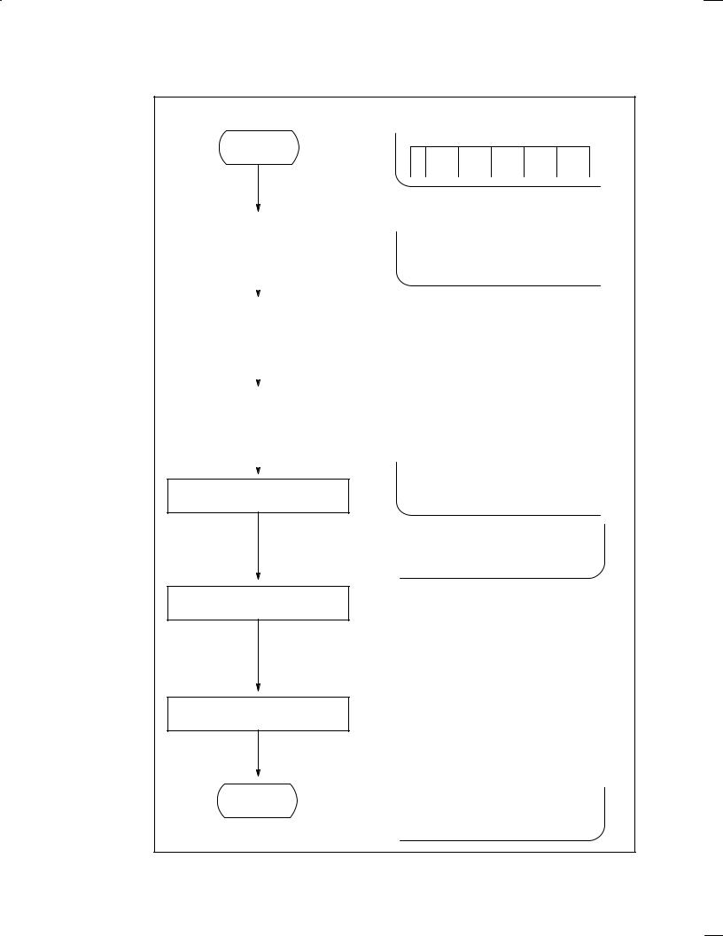
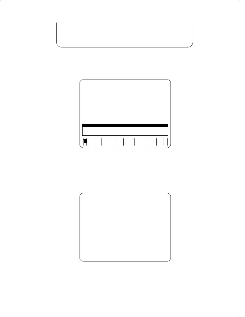
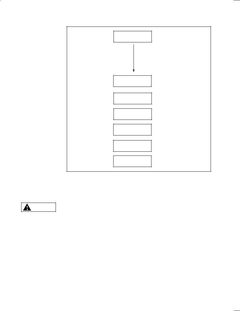
1.2 Creating a Machining Program [Basic Menu 1]
A machining program is created by the following procedure:
Start
|
1 |
2 |
3 |
4 |
|
|
|
|
|
|
Program creation screen |
> INPUT PROGRAM NO. |
|
|
||||||||
|
|
|
|
|
|
|
|
|
|
|||
|
|
|
|
|
|
|
|
|
|
|
|
|
|
|
|
|
|
|
|
|
|
EXEC |
|
SEARCH |
|
|
|
|
|
|
|
|
|
|
|
|
||
|
|
Automatic |
|
|
|
|
|
|
|
|
|
|
|
|
|
|
|
|
|
|
|
|
|
||
|
|
|
|
± Enter a program name. |
|
|
||||||
|
|
|
|
|
|
|||||||
|
Title input |
|
|
|
||||||||
|
|
|
|
|
|
|
|
|
|
|
||
|
|
|
|
|
|
|
|
|
|
|
|
|
|
|
|
|
|
|
|
|
|
|
|
|
|
Initial setting |
± Enter the initial data (workpiece material, coolant, |
||
reference coordinate system) required for machining. |
|||
|
|
||
|
|
± Select a desired machining menu. |
|
|
|
|
|
Selection of a machining menu
|
|
|
HOLE |
FACING |
SIDE |
NC |
|
|
|
|
|||||
|
|
|
|
|
CUTING |
/GROOV |
LAN- |
|
|
|
|
|
|
|
GUAGE |
2+1/2 |
2+1/2 |
AUX- |
|
PROGRM |
|
|
|
|
|
|
|
||||
CVX |
CCV |
ILIARY |
|
END |
|
||
|
|
|
|
|
|
|
|
Specification of the machining data
(*1)
(*2)
Program end
End
±In response to messages displayed on the screen,
(1)Specify a machining method. → Position on the Z±axis, tool (preparation menu)
(2)Specify the figure data. → Positions on the X± and Y±axes (figure menu)
(3)Specify the process end.
Repeat these steps until all machining data is speci fied.
± Select [PROGRM END].
2+1/2 |
2+1/2 |
AUX- |
|
PROGRM |
|
|
|
|
|
|
|
||||
CVX |
CCV |
ILIARY |
|
END |
|
|
|
|
|
|
|
|
|
|
|
± 12 ±
B±62154E/03 |
FANUC Super CAP II M |
|
|
|
|
First, the operator selects a machining menu, then enters the type of machining, figure of product, and other data in response to inquiries on the screen. The operator repeats this process to generate a machining program.
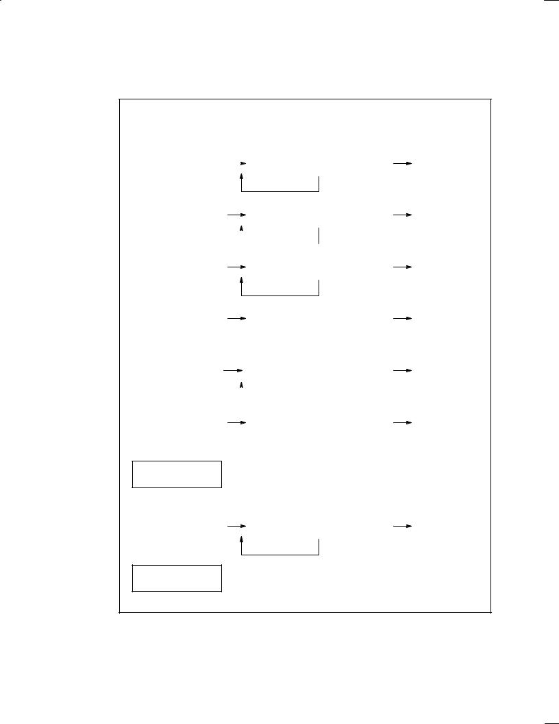
*1 The machining data is specified in the following procedures. The menu of (1) below is automatically displayed only once immediately after the machining menu is selected.
|
|
|
|
|
|
|
|
|
|
|
|
(1) |
(2) |
|
|
(3) |
|||||
|
Preparation menu |
|
|
|
|
Figure menu |
Process end |
|||
. |
|
|
|
|
|
|
|
|
|
|
Drilling |
|
|
|
|
Hole position |
|
|
Process end |
||
|
|
|
|
|
|
|||||
|
|
|
|
|
|
|
|
|
|
|
|
|
|
|
|
|
|
This step can be repeated. |
|
||
. |
|
|
|
|
|
|
|
|
|
|
Facing start menu |
|
|
|
|
Corresponding facing menu |
|
|
Process end |
||
|
|
|
|
|
|
|
|
|
|
|
|
|
|
|
|
|
|
This step can be repeated. |
|
||
. |
|
|
|
|
|
|
|
|
|
|
|
|
|
|
|
|
|
|
|
|
|
Side cutting start menu |
|
|
|
|
Corresponding side cutting menu |
|
|
Process end |
||
|
|
|
|
|
|
|
|
|
|
|
|
|
|
|
|
|
|
This step can be repeated. |
|
||
. |
|
|
|
|
|
|
|
|
|
|
Contouring start menu |
|
|
|
|
Corresponding contouring menu |
|
|
Contour end |
||
|
|
|
|
|
|
|
|
|
|
|
. |
Pocketing start menu |
|
|
Corresponding pocket cutting menu |
|
|
Process end |
|
|
|
|
|
|
|
|
|
|
|
|
|
|
|
This step can be repeated. |
|
||
|
|
|
|
|
|
|
|
|
|
|
|
|
|
|
|
|
|
. |
Contour pocket / |
|
|
Corresponding contouring menu |
|
|
Contour end |
|
grooving start menu |
|
|
|
|
||||
|
|
|
|
|
|
|
|
|
|
|
|
|
|
|
|
|
|
. NC language
. |
2 +1/2 start |
|
Corresponding 2 +1/2 menu |
|
Process end |
|
|
|
|
|
|
This step can be repeated.
. Auxiliary
A single machining process has the machining data of the start menu, figure menu, and [PROCES END]. The system checks whether the machining data consists of the above three elements and prevents the operator from creating a machining program which cannot be executed.
± 13 ±
FANUC Super CAP II M B±62154E/03
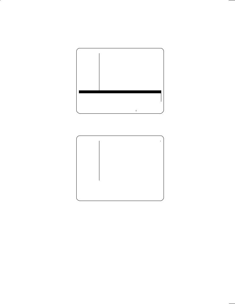
*2 The screen on which the machining data is specified is basically configured as shown below. The A, B, and C windows show different data.
A |
B |
|
|
C
|
|
Ten soft keys |
|
Next key |
Return key |
|
|
||
|
|
|
||
A: Program screen that is always displayed. The data in the B and C windows depend on the data input. The A window always lists the existing programs.
B: Guide screen that displays the data of the C window with a drawing or tool file. The cursor is placed on the corresponding parameter in the C window.
C: Data input screen. Basically, the data (parameter) is displayed and specified in this window. The data which cannot be displayed in this window (data to be determined automatically,cuting conditions, etc.) is displayed and specified in the B window.
Return key : Displays the previous screen. When the return key can be used, [<] is indicated here.
Next key : Displays the next part of the currently displayed sof keys.
When the next key can be used, [+] is indicated here.
± 14 ±
B±62154E/03 |
FANUC Super CAP II M |
|
|
|
|
Examples are given below:
WARNING
1.
The machining programs presented in the following examples differ from those used for actual machining. Actual data will vary from one machine model to another. Refer to the relevant manual(s), supplied by the machine tool builder, for details.
If the set data is incompatible with the characteristics of a specific machine, a machining program created using the conversational function will not be able to operate as intended.
If a machining program fails to operate correctly, the tool may collide with the workpiece, or the machine may be forced to perform machining that exceeds its physical capabilities, possibly causing damage to the tool and/or machine, or even injury to the user or bystanders.
Select [1] on the basic menu screen. The following program list screen is displayed: (For details of the program list, see Subsec. 1.8.1.)
PROGRAM |
DIR. |
|
PAGE 01/01 |
EDIT |
|
|
|
|
|
PROGRAM NO. USED: |
|
7 FREE: |
99 |
|
|
|
MEMORY AREA USED: |
560 FREE: |
3704 |
|
NO. |
TYPE |
NAME |
CREATE DATA |
SIZE |
||
0001 |
CAP |
TEST±1 DEMO |
94±10±06 11:47 |
80 |
||
0002 |
CAP |
TEST±2 SUS304 |
94±10±06 11:49 |
80 |
||
0003 |
CAP |
TEST±3 FCD45 |
94±10±06 11:50 |
80 |
||
0004 |
CAP |
TEST±4 SKD11 |
94±10±06 11:51 |
80 |
||
0005 |
CAP |
TEST±5 SUS41 |
94±10±06 11:52 |
80 |
||
0006 |
CAP |
TEST±6 ALUME |
94±10±06 11:53 |
80 |
||
0007 |
CAP |
TEST±7 SPECIAL |
94±10±06 11:56 |
80 |
||
INPUT PROGRAM NO. |
|
|
|
|
>_ |
|
|||||||||
|
|
|
|
|
|
|
|
|
|
|
|
|
|
|
|
|
|
|
|
PROG. |
|
|
|
|
|
PROG. |
PROG. |
MODIFY |
LI- |
|
|
|
< |
|
|
|
|
|
|
|
|
||||||
|
|
|
|
SELECT |
|
|
|
|
|
COPY |
DELETE |
TITLE |
BRARY |
|
|
|
|
|
|
|
|
|
|
|
|
|
|
|
|
|
|
2.Enter program number 1000 and press the [PROG. SELECT] key. (When the program is present, the editing screen is displayed. See the next section.) A program can also be created by entering a program number and pressing the <INPUT> key in MDI. When a new program is to be created, the name input screen is automatically displayed in the bottom window.
On this screen, specify a desired program name of up to 16 alphanumeric characters, entered using the MDI keys. Then, press the [INPUT TITLE] key. The program name is registered in part program storage. The program name can also be registered by pressing the MDI <INPUT> key. To abandon the registration, press the [CANCEL] key.
PROGRAM |
DIR. |
|
PAGE 01/01 |
CREATE |
|
|
|
|
|
PROGRAM NO. USED: |
|
8 FREE: |
99 |
|
|
|
MEMORY AREA USED: |
640 FREE: |
3696 |
|
NO. |
TYPE |
NAME |
CREATE DATA |
SIZE |
||
0001 |
CAP |
TEST±1 DEMO |
94±10±06 11:47 |
80 |
||
0002 |
CAP |
TEST±2 SUS304 |
94±10±06 11:49 |
80 |
||
0003 |
CAP |
TEST±3 FCD45 |
94±10±06 11:50 |
80 |
||
0004 |
CAP |
TEST±4 SKD11 |
94±10±06 11:51 |
80 |
||
0005 |
CAP |
TEST±5 SUS41 |
94±10±06 11:52 |
80 |
||
0006 |
CAP |
TEST±6 ALUME |
94±10±06 11:53 |
80 |
||
0007 |
CAP |
TEST±7 SPECIAL |
94±10±06 11:56 |
80 |
||
1000 |
NC |
|
|
|
|
|
TITLE INPUT : 1
PROG. TITLE : =MANUAL±1_
INPUT PROGRAM TITLE.(WITHIN 16 CHAR)
<INPUT CANCEL TITLE
± 15 ±
FANUC Super CAP II M |
B±62154E/03 |
|
|
|
|
3.When the [INPUT TITLE] key is pressed, the initial setting screen is automatically displayed in the lower window, as shown below:
When the cursor is positioned to an entry in window C, a message relating to the entry is displayed above the soft keys. The operator usually enters necessary data, as instructed by the message. On the guidance in window B, the second cursor blinks at the position corresponding to the current entry. Being able to see both cursors enables the easy input of data.
PROGRAM |
|
|
O1000(MANUAL±1) |
|
|
PAGE :01/ |
CREATING |
|
|
||||||||||||
|
|
|
|
|
|
|
|
|
|
|
|
MATERIAL,COOLANT AND Z SEFTY LMT |
|
||||||||
NO. CYCLE |
|
|
PROCESS |
TOOL NAME |
ARE SURE TO INPUT. |
|
|
|
|
|
|||||||||||
|
|
|
|
|
|
|
|
|
|
|
|
Y |
|
|
Y |
|
Y |
|
|||
|
|
|
|
|
|
|
|
|
|
|
|
WORK |
|
WORK |
|
WORK |
... |
||||
|
|
|
|
|
|
|
|
|
|
|
|
CO 1 |
|
CO 2 |
|
CO 3 |
|||||
|
|
|
|
|
|
|
|
|
|
|
|
|
|
|
|||||||
|
|
|
|
|
|
|
|
|
|
|
|
(G54) |
|
(G55) |
|
(G56) |
|
||||
|
|
|
|
|
|
|
|
|
|
|
|
|
X |
|
|
|
X |
|
|
X |
|
|
|
|
|
|
|
|
|
|
|
|
|
|
|
MACHINE |
|
|
|
|
|
||
|
|
|
|
|
|
|
|
|
|
|
|
|
Z |
ZERO |
|
|
|
|
|
||
|
|
|
|
|
|
|
|
|
|
|
|
|
|
POINT |
|
I |
|
||||
|
|
|
|
|
|
|
|
|
|
|
|
|
|
|
|
|
|
|
|||
|
|
|
|
|
|
|
|
|
|
|
|
X |
|
|
|
|
Y |
|
|
|
|
|
|
|
|
|
|
|
|
|
|
|
|
|
|
|
|
Z SAFETY LMT |
|||||
|
|
|
|
|
|
|
|
|
|
|
|
|
WORK COORDINATES |
|
|
|
|
||||
AUXILIARY |
:INITAL SETING |
|
1/2 |
|
|
|
|
|
|
|
|
|
|
|
|||||||
MATERIAL |
: Q= |
|
|
|
X AXIS |
: X= |
* |
|
WORK SHAPE |
: C= |
* |
||||||||||
COOLANT |
: M= |
|
|
|
Y AXIS |
: Y= |
* |
|
MAT X CO±ORD:YA= |
* |
|||||||||||
Z SAFTY LMT : I= |
|
|
Z AXIS |
: Z= |
* |
|
MAT Y CO±ORD:YB= |
* |
|||||||||||||
COORDINATES : W= |
WORK CO 1 B AXIS |
: B= |
* |
|
MAT Z CO±ORD:YC= |
* |
|||||||||||||||
|
|
|
|
|
|
|
|
|
|
|
|
|
|
|
|
|
|
|
|
|
|
|
< |
|
GRAY |
DCTIL |
LOLED |
CARBON |
ALLOY |
|
STAINL |
ALMI- |
|
SPE- |
GUIDAN |
INPUT |
|
||||||
|
|
|
CAST |
CAST |
STL |
STL |
STL |
|
ESS |
NUM |
|
CIAL |
CE |
|
END |
|
|||||
|
|
|
|
|
|
|
|
|
|
|
|
|
|
|
|
|
|
|
|
|
|
After completing input of the initial setting data, ensure that all required data is set correctly. WARNING If any data is not set correctly, machining will be performed under abnormal cutting conditions,
such that the workpiece may be damaged or the tool may collide with the machine and/or workpiece, possibly causing damage to the tool and/or machine, or even injury to the user or bystanders.
The soft keys that are displayed depends on the position of the cursor. In the example below, the soft key indicated by is selected:
± When the cursor is on [Q: MATERIAL]
|
|
|
GRAY |
DCTIL |
LOLED |
CARBON |
ALLOY |
|
STAINL |
ALMI- |
SPE- |
GUID- |
INPUT |
|
|
|
|
|
|
|
|
|
|
||||||||||
|
|
|
CAST |
CAST |
CAST |
STL |
STL |
|
ESS |
NUM |
CIAL |
ANCE |
END |
|
||
|
|
|
|
|
|
|
|
|
|
|
|
|
|
|
|
|
± When the cursor is on [M: COOLANT]
|
|
|
COOLNT |
COOLNT |
OFF |
|
|
|
|
|
|
|
|
|
|
|
|
|
|
|
|
|
|
|
|
|
|
|
|
|
|||
|
|
|
M7 |
M8 |
M9 |
|
|
|
|
|
|
|
|
|
|
|
|
|
|
|
|
|
|
|
|
|
|
|
|
|
|
|
|
± When the cursor is on [W: COORDINATES]
|
|
|
WOK |
WORK |
WORK |
WORK |
WORK |
|
WORK |
WORK |
|
|
|
|
|
|
|
|
|
|
|
|
|
|
|
|
|||||||
|
|
|
CO SET |
CO 1 |
CO 2 |
CO 3 |
CO 4 |
|
CO 5 |
CO 6 |
|
|
|
|
|
|
|
|
|
|
|
|
|
|
|
|
|
|
|
|
|
|
|
± 16 ±
B±62154E/03 |
FANUC Super CAP II M |
|
|
|
|
4. Of the following soft keys select the [GUIDANCE] key:
|
|
|
|
F.S. |
|
|
WINDOW |
|
|
|
TOOL |
GUID- |
INPUT |
|
|
|
|
|
|
|
|
|
|
|
|
|
|
|
|||||
|
|
|
|
AOUT |
|
|
CHANGE |
|
|
|
INPORM |
ANCE |
END |
|
||
|
|
|
|
|
|
|
|
|
|
|
|
|
|
|
|
|
The guidance in the B window disappears and the screen shown below is displayed. After the guidance is turned off, screens displayed later on do not contain the guidance. Operators familiar with this system can enter the data only with messages, without the guidance. When the soft key [GUIDANCE] is pressed again, the guidance is turned on (the soft key display is reversed; that is, reverse video). In this data, the screens displayed later contain the guidance.
PROGRAM |
O1000 |
|
PAGE |
:01/ |
|
CREATING |
|
NO. CYCLE |
PROCESS |
TOOL NAME |
TOOL |
NO |
N±DIA FEED SPINDL |
||
PROGRAM DIR.: 1
MATERIAL |
: Q= |
GRAY CAST X AXIS |
: X= |
* |
MM OR INCH : A=G21 MM |
|
COOLANT |
: M= |
COOLNT M7 |
Y AXIS |
: Y= |
* |
|
Z SAFTY LMT |
: I= |
20 |
Z AXIS |
: Z= |
* |
|
COORDINATES |
: W= |
WORK CO 1 |
B AXIS |
: B= |
|
* |
INPUT THE Z COORD WHICH DO NOT INTERFERE WITH WORKPIECE AND JIG.
< |
GUIDAN |
INPUT |
|
CE |
END |
5.After entering all desired data, press the soft key [INPUT END]. The system automatically checks the input data. If the system finds an invalid value among the input data, the cursor is placed on that data and an alarm message is displayed. If all the input data is correct, the program creation screen is displayed again. The process of initial setting is incorporated into the following screen:
NOTE If the <INPUT> key is pressed, the cursor is moved to the next option. Only pressing the <INPUT> key does not change the current option. If the <INPUT> key is pressed after a value is specified, the value is entered as the data. If the <INPUT> key is pressed without specifying a value, the cursor moves to the next option and no data is entered.
PROGRAM |
O1000 |
|
PAGE :01/ |
|
CREATING |
|
NO. CYCLE |
PROCESS |
TOOL NAME |
TOOL NO |
N±DIA FEED SPINDL |
||
001 AUXILIARY |
INITAL |
|
|
|
|
|
SELECT SOFTKEY.
|
HOLE |
FACING |
SIDE C |
NC LAN |
|
2+1/2 |
2+1/2 |
AUXILI |
|
PROGRM |
|
|
< |
|
|
|
|||||||||
|
|
|
||||||||||
|
|
|
UTING |
TING |
GUAGE |
|
CVX |
CCV |
ARY |
|
END |
|
|
|
|
|
|
|
|
|
|
|
|
|
|
± 17 ±

FANUC Super CAP II M |
B±62154E/03 |
|
|
|
|
6.Select a desired machining menu. When the soft key [FACING] is selected, for example, the following screen is displayed:
PROGRAM |
|
O1000 |
|
|
PAGE :01/ |
CREATING |
||
01 |
SQUARE |
UNIDIR |
02 |
SQUARE BIDIR |
03 |
CIRCLE |
UNIDIR |
|
04 |
CIRCLE |
BIDIR |
05 |
SQUAREFRING |
06 |
CIRCLE |
DRING |
|
07 |
COPY RANDOM |
08 |
COPY PATTRN |
|
|
|
|
|
WHEN COPYING EACH MENU,SELECT EITHER ONE
IN ADVANCE.
SELECT SOFTKEY.
|
|
|
|
|
|
|
|
|
|
|
|
|
< |
01 |
02 |
03 |
04 |
05 |
|
06 |
07 |
08 |
GUIDAN |
PROCES |
|
|
|
|
|
|
|
|
|
|
CE |
END |
|
|
|
|
|
|
|
|
|
|
|
|
|
|
|
7.When the soft key [GUIDANCE] is pressed, the following screen is displayed. The numeric values indicated on the soft keys are changed to characters.
PROGRAM |
O1000 |
|
PAGE :01/ |
|
CREATING |
|
NO. CYCLE |
PROCESS |
TOOL NAME |
TOOL NO |
N±DIA FEED SPINDL |
||
001 AUXILIARY |
INITAL SETING |
|
|
|
|
|
|
|
|
|
|
|
|
SELECT SOFTKEY.
<SQUARE SQUARE CIRCLE CIRCLE SQUARE UNIDI BIDIR UNIDI BIDIR FRING
CIRCLE |
COPY |
COPY |
GUIDAN |
PROCES |
|
DRING |
RANDOM |
PATTRN |
CE |
END |
|
|
|
|
|
|
|
8.Select a detailed menu required for facing. When the soft key [SQUARE BIDIR] is selected, for example, the facing start menu (tool data input) is automatically displayed in the bottom window, C, and the right window, B.
PROGRAM |
|
O1000 |
|
|
PAGE :01/ |
CREATING |
|
|
|
|
|
|
MAX NUM.OF TOOLS±2 |
NO. CYCLE |
|
PROCESS |
TOOL NAME |
|
|
|
001 AUXILIARY |
INITAL SETING |
|
T |
|
||
|
|
|
||||
|
|
|
|
|
E*2D |
|
|
|
|
|
|
|
K |
|
|
|
|
|
|
J |
|
|
|
|
|
|
V Y |
|
|
|
|
|
|
Z |
|
|
|
|
|
|
U |
FACING |
:FACING PREP. |
|
|
|
|
|
GROUP COPY |
:YB= |
UNUSED FINISHING |
: Y= |
0. |
|
|
Z POINT |
: Z= |
|
THICKNESS |
: U= |
|
|
REMOVAL |
: V= |
|
TOOL ID NO. : T= |
|
|
|
PITCH |
: J= |
|
|
|
|
|
INPUT THE Z COORD OF THE FINAL MACHINED SURFACE.
|
|
|
|
|
|
|
|
|
|
|
|
|
< |
|
F.S. |
|
|
PROCES |
|
|
|
TOOL |
GUIDAN |
INPUT |
|
|
|
|
|
|
|
|
||||||
|
|
AUTO |
|
|
WINDOW |
|
|
|
INFORM |
CE |
END |
|
|
|
|
|
|
|
|
||||||
|
|
|
|
|
|
|
|
|
|
|
|
|
± 18 ±
B±62154E/03 |
FANUC Super CAP II M |
|
|
|
|
9.Enter desired data, responding to messages and checking the guidance. When the system asks about the tool ID number, enter the ID number of the last tool (the tool to be used last in that machining, excluding chamfering tools). If required, press the soft key [TOOL INFORM]. The system displays the following screen, on which the required tool ID number can be easily checked and specified.
NOTE After the soft key [TOOL INFORM] is pressed, the soft key [DIVIDE TOLDIR] is always displayed. The tool types are specified in parameters Nos. 9304 to 9343. On that screen, the other tool information (pre±tool list, tool file, tool list) can be specified and referenced.
PROGRAM |
O1000 |
|
|
PAGE :01/ |
CREATING |
|
|
DIVIDE TOLDIR: 1 |
|
|
|
||
NO. CYCLE |
PROTOOL NAME |
FACE MILL |
|
|
|
|
001 AUXILIARY |
INI TOOL NO. |
N±DIA. |
MATERIAL |
T±CODE |
D±CODE |
|
|
1 |
71 |
30.000 |
HIGH±SPEED |
71 |
71 |
|
2 |
72 |
40.000 |
SPECIAL |
72 |
72 |
|
3 |
73 |
50.000 |
CARBIDE |
73 |
73 |
|
4 |
74 |
60.000 |
HIGH±SPEED |
74 |
74 |
|
5 |
75 |
80.000 |
SPECIAL |
75 |
75 |
|
6 |
76 |
80.000 |
CARBIDE |
76 |
76 |
|
7 |
77 |
100.000 |
HIGH±SPEED |
77 |
77 |
|
8 |
78 |
120.000 |
SPECIAL |
78 |
78 |
|
9 |
79 |
150.000 |
CARBIDE |
79 |
79 |
|
10 |
80 |
200.000 |
HIGH±SPEED |
80 |
80 |
|
|
|
|
|
|
|
FACING |
:FACING PREP. |
|
|
||
GROUP COPY |
:YB= |
UNUSED FINISHING |
: Y= |
0. |
|
Z POINT |
: Z= |
|
THICKNESS |
: U= |
|
REMOVAL |
: V= |
|
TOOL ID NO. : T= |
|
|
PITCH |
: J= |
|
|
|
|
INPUT THE Z COORD OF THE FINAL MACHINED SURFACE.
|
|
|
|
|
|
|
|
|
|
|
|
|
< |
|
|
|
|
WINDOW |
|
TOOL |
DIVIDE |
TOOL |
PRE± |
|
|
|
|
|
|
|
|
|
||||||
|
|
|
|
|
CHANGE |
|
DRCTRY |
TOLDIR |
FILE |
TOOL |
|
|
|
|
|
|
|
|
|
|
|||||
|
|
|
|
|
|
|
|
|
|
|
|
|
10.After specifying the tool ID number, press the <INPUT> key. The automatic tool selection function(*1) and automatic cutting condition function(*2) are executed. The cutting conditions automatically selected by the two functions are indicated at the right corner of the screen.
PROGRAM |
|
|
O1000 |
|
|
|
|
PAGE :01/ |
CREATING |
|
|
|
||||||
|
|
|
|
|
CUTTING DATA1/1PROCESS 2 |
PROCESS 1 |
|
|
|
|||||||||
NO. CYCLE |
|
|
|
|
|
|
72. |
|
|
|
|
|
|
|
|
|||
|
|
PROT OL ID NO. |
T= |
|
72. |
|
|
|
|
|
||||||||
001 AUXILIARY |
|
INITOOL NAME |
Q= FACE MILL |
FACE MILL |
|
|
|
|||||||||||
|
|
|
|
|
PROCESS |
B= FINISHING |
ROUGHING |
|
|
|
||||||||
|
|
|
|
|
H OFFSET NO. |
H= |
172. |
172. |
|
|
|
|
|
|||||
|
|
|
|
|
D OFFSET NO. |
D= |
72. |
72. |
|
|
|
|
|
|||||
|
|
|
|
|
COOLANT |
M=COOLNT M7 |
COOLNT M7 |
|
|
|
||||||||
|
|
|
|
|
SPINDL SPEED |
S= |
1431. |
1431. |
|
|
|
|
|
|||||
|
|
|
|
|
FEED RATE |
F= |
773. |
773. |
|
|
|
|
|
|||||
|
|
|
|
|
CUT WIDTH(%) |
E= |
70. |
70. |
|
|
|
|
|
|||||
|
|
|
|
|
Z±ESCAPE |
K= |
3. |
3. |
|
|
|
|
|
|||||
|
|
|
|
|
|
|
|
|
|
|
|
|
|
|
|
|
|
|
FACING |
:FACING |
|
|
|
|
|
|
|
|
|
|
|
|
|
||||
GROUP COPY |
:YB= |
|
UNUSED FINISHING |
: Y= |
2. |
|
|
|
|
|
||||||||
Z POINT |
: Z= |
|
|
0. THICKNESS |
: U= |
100. |
|
|
|
|
|
|||||||
REMOVAL |
: V= |
|
20. TOOL ID NO. : T= |
72. |
|
|
|
|
|
|||||||||
PITCH |
: J= |
5. |
|
|
|
|
|
|
|
|
|
|
|
|
||||
INPUT THE TOOL ID NUMBER OF THE TOOL TO BE USED. |
|
|
|
|||||||||||||||
|
|
|
|
|
|
|
|
|
|
|
|
|
|
|
|
|
|
|
|
< |
|
F.S. |
|
|
|
WINDOW |
|
|
|
|
TOOL |
GUIDAN |
INPUT |
|
|||
|
|
|
AUTO |
|
|
|
CHANGE |
|
|
|
|
INFORM |
CE |
END |
|
|||
|
|
|
|
|
|
|
|
|
|
|
|
|
|
|
|
|
|
|
± 19 ±
FANUC Super CAP II M |
B±62154E/03 |
|
|
|
|
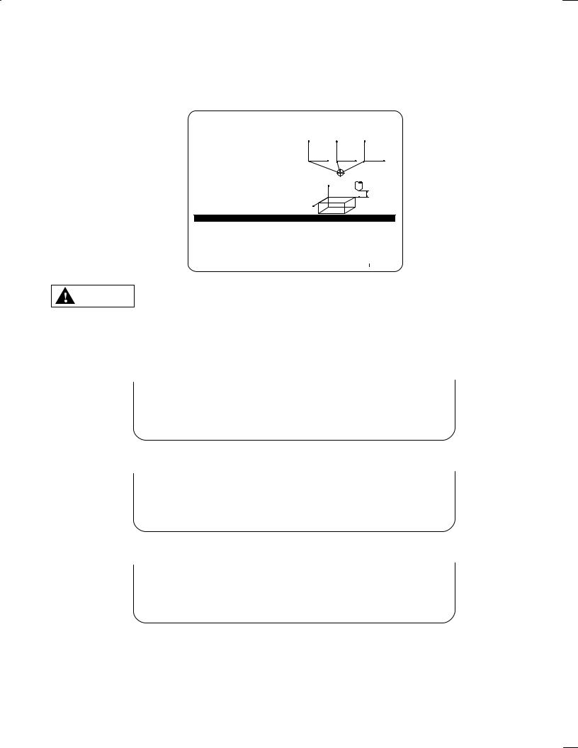
NOTE 1 Automatic tool selection function: After the ID number of the last tool (72, in this example) is entered, the function automatically selects the pre±tools required for facing (roughing tool 71, in this example). It also displays the ID numbers of the pre±tools.
When a tap is specified as the last tool in tapping, for example, a center drilling tool to make a prepared hole, drilling tool, and chamfering tool are automatically selected.
Tap
Automatic tool selection
Center drilling tool
Drilling tool
Chamfering tool
Tap
The pre±tools to be used are selected based on the data specified in the pre±tool list. When the automatic tool selection function is used to select pre±tools, be sure to specify the pre±tool data in the pre±tool list before starting the program. (See the description of the pre±tool list in Section 1.7.) If no data is specified in the pre±tool list, the last tool is also automatically selected as a pre±tool.
When a machining program is created using the automatic tool selection function, ensure that WARNING the generated machining sequence and the tools to be used are satisfactory.
If the machining sequence or a tool to be used is not as intended, the tool may collide with the workpiece, or the machine may be forced to perform machining that exceeds its physical capabilities, possibly causing damage to the tool and/or machine, or even injury to the user or bystanders.
± 20 ±
B±62154E/03 |
FANUC Super CAP II M |
|
|
|
|
NOTE 2 Automatic cutting condition function: Automatically selects and displays the name, nominal diameter, and other data of each tool selected by the automatic tool selection function.
Tool ID number
Automatic cutting condition
Tool name
Nominal diameter
Compensation number
Coolant
Spindle speed
Feedrate
The function determines the tool name, nominal diameter, and tool length compensation number according to the data specified in the tool file. It determines the spindle speed, feedrate, and other cutting conditions according to the data specified in the cutting conditions file and the work material specified on the initial setting menu. It can correctly select the tool name and other data only when the correct data is specified in the tool file, cutting conditions file, and the initial setting menu. (See the descriptions of the tool file and cutting conditions file in Section 1.7.)
The cutting conditions are determined automatically according to the selected machining type WARNING and tools. The user must check that the automatically determined data is satisfactory.
If any of the cutting condition data or a tool to be used is not as intended, the tool may collide with the workpiece, or the machine may be forced to perform machining that exceeds its physical capabilities, possibly causing damage to the tool and/or machine, or even injury to the user or bystanders.
± 21 ±
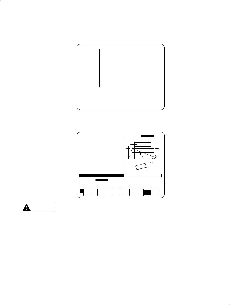
FANUC Super CAP II M |
B±62154E/03 |
|
|
|
|
11.To change the machining conditions selected by the automatic tool selection function and automatic cutting condition function, press the soft key [WINDOW CHANGE]. The cursor is moved to the machining condition screen. Place the cursor on the data to be changed and enter desired data. To change the tool ID number and automatically specify it, press the soft key [F.S.AUTO]. The automatic cutting condition function is executed for the tool and the corresponding cutting conditions are displayed. To return the cursor to the C window, press the soft key [WINDOW CHANGE].
PROGRAM |
|
|
O1000 |
|
|
|
|
PAGE :01/ |
CREATING |
|
|
|
||||||
|
|
|
|
|
CUTTING DATA1/1PROCESS 2 |
PROCESS 1 |
|
|
|
|||||||||
NO. CYCLE |
|
|
PROT OL ID NO. |
T= |
73. |
72. |
|
|
|
|
|
|||||||
001 AUXILIARY |
|
INITOOL NAME |
Q= FACE MILL |
FACE MILL |
|
|
|
|||||||||||
|
|
|
|
|
PROCESS |
B= FINISHING |
ROUGHING |
|
|
|
||||||||
|
|
|
|
|
H OFFSET NO. |
H= |
173. |
172. |
|
|
|
|
|
|||||
|
|
|
|
|
D OFFSET NO. |
D= |
73. |
72. |
|
|
|
|
|
|||||
|
|
|
|
|
COOLANT |
M=COOLNT M7 |
COOLNT M7 |
|
|
|
||||||||
|
|
|
|
|
SPINDL SPEED |
S= |
572. |
1431. |
|
|
|
|
|
|||||
|
|
|
|
|
FEED RATE |
F= |
309. |
773. |
|
|
|
|
|
|||||
|
|
|
|
|
CUT WIDTH(%) |
E= |
70. |
70. |
|
|
|
|
|
|||||
|
|
|
|
|
Z±ESCAPE |
K= |
3. |
3. |
|
|
|
|
|
|||||
|
|
|
|
|
|
|
|
|
|
|
|
|
|
|
|
|
|
|
FACING |
:FACING PREP. |
|
|
|
|
|
|
|
|
|
|
|
|
|||||
GROUP COPY |
:YB= |
|
UNUSED FINISHING |
: Y= |
2. |
|
|
|
|
|
||||||||
Z POINT |
: Z= |
|
|
0. THICKNESS |
: U= |
100. |
|
|
|
|
|
|||||||
REMOVAL |
: V= |
|
20. TOOL ID NO. : T= |
|
72. |
|
|
|
|
|
|
|||||||
PITCH |
: J= |
5. |
|
|
|
|
|
|
|
|
|
|
|
|
||||
INPUT THE TOOL ID NUMBER OF THE TOOL TO BE USED. |
|
|
|
|||||||||||||||
|
|
|
|
|
|
|
|
|
|
|
|
|
|
|
|
|
|
|
|
< |
|
F.S. |
|
|
|
WINDOW |
|
|
|
|
|
TOOL |
GUIDAN |
INPUT |
|
||
|
|
|
AUTO |
|
|
|
CHANGE |
|
|
|
|
|
INFORM |
CE |
END |
|
||
|
|
|
|
|
|
|
|
|
|
|
|
|
|
|
|
|
|
|
12.After checking that all data is correctly entered, press the soft key [INPUT END]. The system automatically checks all the input data. If all the data is correct, the facing start process is incorporated into the program and menu of [SQUARE BIDIR] is automatically displayed in the window.
PROGRAM |
|
O1000 |
|
|
PAGE :01/ |
CREATING |
|
||
NO. CYCLE |
|
PROCESS |
|
TOOL NAME |
|
U |
|
|
|
001 AUXILIARY |
INITAL SETING |
|
|
YD |
|
|
|
||
|
|
|
|
|
|
||||
002 FACING |
|
FACING PREP. |
FACE MILL (1) |
|
|
|
(2) |
||
|
|
FACING PREP. |
FACE MILL |
|
|
|
|
||
|
|
|
|
|
V |
(X,Y) |
|
|
|
|
|
|
|
|
(3) |
|
(4) |
||
|
|
|
|
|
|
|
|
||
|
|
|
|
|
|
|
|
YC |
|
|
|
|
|
|
|
|
|
A |
|
FACING |
:SQUARE BIDIR |
|
|
|
|
|
|
|
|
COORDINATES : W= |
* |
V LENGTH |
: V= |
ESCAPE |
:YD= |
5. |
|||
X CO±ORD |
: X= |
|
ANGLE |
|
: A= |
0. |
|
|
|
Y CO±ORD |
: Y= |
|
START POINT |
: B= |
(4) |
|
|
|
|
U LENGTH |
: U= |
|
APPROACH |
:YC= |
5. |
|
|
|
|
INPUT THE X COORD OF THE CENTER OF THE QUADRANGLE.
< |
GUIDAN |
INPUT |
|
CE |
END |
After figure data has been entered, check that the specified figure can actually be machined us- WARNING ing the selected machining type and tools.
If the figure is not specified correctly, the tool may collide with the workpiece and/or machine, possibly causing damage to the tool and/or machine, or even injury to the user or bystanders.
± 22 ±
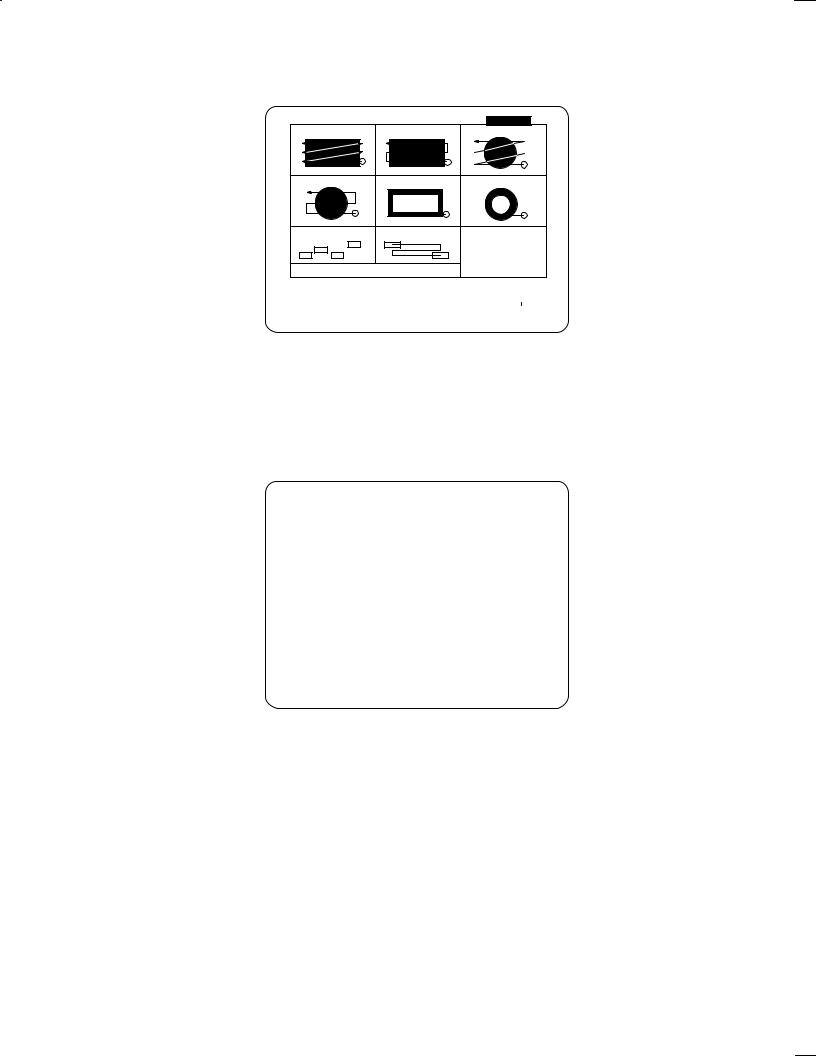
B±62154E/03 |
FANUC Super CAP II M |
|
|
|
|
13.Enter desired machining data and press the soft key [INPUT END]. The system automatically checks the input data. If all the data is correct, the square two±way facing process is incorporated into the program. The detailed menu screen for facing is displayed again.
PROGRAM |
|
O1000 |
|
|
PAGE :01/ |
CREATING |
||
01 |
SQUARE |
UNIDIR |
02 |
SQUARE BIDIR |
03 |
CIRCLE |
UNIDIR |
|
04 |
CIRCLE |
BIDIR |
05 |
SQUAREFRING |
06 |
CIRCLE |
DRING |
|
07 |
COPY RANDOM |
08 |
COPY PATTRN |
|
|
|
|
|
WHEN COPYING EACH MENU,SELECT EITHER ONE
IN ADVANCE.
SELECT SOFTKEY.
|
|
|
|
|
|
|
|
|
|
|
|
|
< |
01 |
02 |
03 |
04 |
05 |
|
06 |
07 |
08 |
GUIDAN |
PROCES |
|
|
|
|
|
|
|
|
|
|
CE |
END |
|
|
|
|
|
|
|
|
|
|
|
|
|
|
|
NOTE If the return key, [<], at the bottom left corner of the screen is pressed instead of the soft key [INPUT END], the following message appears on the screen: MAKING PROCESS IS LOST, O.K.? (YES ±> [<], NO ±> [CAN]). When the [<] key is pressed again, the start menu for the preceding process is deleted. This prevents the creation of a machining process which does not consist of a start menu, figure menu, and process end. If the start menu of such a preceding process remains, there is danger that the resultant machining program cannot be executed.
14.To terminate the facing menu, press the soft key [PROCES END]. The first screen is displayed again. The terminated process is incorporated in the program screen.
PROGRAM |
O1000 |
|
PAGE :01/ |
CREATING |
|
|||
NO. CYCLE |
PROCESS |
TOOL NAME |
TOOL NO |
N±DIA |
FEED SPINDL |
|||
001 |
AUXILIARY |
INITAL SETING |
|
|
|
|
|
|
002 |
FACING |
FACING PREP. |
FACE MILL |
72. |
40.000 |
773. |
1431. |
|
|
|
FACING PREP. |
FACE MILL |
73. |
50.000 |
309. |
572. |
|
|
FACING |
SQUARE BIDIR |
|
|
|
|
|
|
|
|
PROCESS END |
|
|
|
|
|
|
|
HOLE |
FACING |
SIDE C |
NC LAN |
|
2+1/2 |
2+1/2 |
AUXILI |
|
PROGRM |
|
|
< |
|
|
|
|||||||||
|
|
|
||||||||||
|
|
|
UTING |
TING |
GUAGE |
|
CVX |
CCV |
ARY |
|
END |
|
|
|
|
|
|
|
|||||||
|
|
|
|
|
|
|
|
|
|
|
|
|
± 23 ±
Loading...